EP3931398B1 - Sicherheitsendstück für strassensperren - Google Patents
Sicherheitsendstück für strassensperren Download PDFInfo
- Publication number
- EP3931398B1 EP3931398B1 EP20700387.2A EP20700387A EP3931398B1 EP 3931398 B1 EP3931398 B1 EP 3931398B1 EP 20700387 A EP20700387 A EP 20700387A EP 3931398 B1 EP3931398 B1 EP 3931398B1
- Authority
- EP
- European Patent Office
- Prior art keywords
- track
- box body
- vertical
- slider
- shaped guide
- Prior art date
- Legal status (The legal status is an assumption and is not a legal conclusion. Google has not performed a legal analysis and makes no representation as to the accuracy of the status listed.)
- Active
Links
Images



Classifications
-
- E—FIXED CONSTRUCTIONS
- E01—CONSTRUCTION OF ROADS, RAILWAYS, OR BRIDGES
- E01F—ADDITIONAL WORK, SUCH AS EQUIPPING ROADS OR THE CONSTRUCTION OF PLATFORMS, HELICOPTER LANDING STAGES, SIGNS, SNOW FENCES, OR THE LIKE
- E01F15/00—Safety arrangements for slowing, redirecting or stopping errant vehicles, e.g. guard posts or bollards; Arrangements for reducing damage to roadside structures due to vehicular impact
- E01F15/14—Safety arrangements for slowing, redirecting or stopping errant vehicles, e.g. guard posts or bollards; Arrangements for reducing damage to roadside structures due to vehicular impact specially adapted for local protection, e.g. for bridge piers, for traffic islands
- E01F15/145—Means for vehicle stopping using impact energy absorbers
- E01F15/146—Means for vehicle stopping using impact energy absorbers fixed arrangements
-
- E—FIXED CONSTRUCTIONS
- E01—CONSTRUCTION OF ROADS, RAILWAYS, OR BRIDGES
- E01F—ADDITIONAL WORK, SUCH AS EQUIPPING ROADS OR THE CONSTRUCTION OF PLATFORMS, HELICOPTER LANDING STAGES, SIGNS, SNOW FENCES, OR THE LIKE
- E01F15/00—Safety arrangements for slowing, redirecting or stopping errant vehicles, e.g. guard posts or bollards; Arrangements for reducing damage to roadside structures due to vehicular impact
- E01F15/02—Continuous barriers extending along roads or between traffic lanes
- E01F15/04—Continuous barriers extending along roads or between traffic lanes essentially made of longitudinal beams or rigid strips supported above ground at spaced points
- E01F15/0407—Metal rails
- E01F15/0438—Spacers between rails and posts, e.g. energy-absorbing means
-
- E—FIXED CONSTRUCTIONS
- E01—CONSTRUCTION OF ROADS, RAILWAYS, OR BRIDGES
- E01F—ADDITIONAL WORK, SUCH AS EQUIPPING ROADS OR THE CONSTRUCTION OF PLATFORMS, HELICOPTER LANDING STAGES, SIGNS, SNOW FENCES, OR THE LIKE
- E01F15/00—Safety arrangements for slowing, redirecting or stopping errant vehicles, e.g. guard posts or bollards; Arrangements for reducing damage to roadside structures due to vehicular impact
- E01F15/02—Continuous barriers extending along roads or between traffic lanes
- E01F15/04—Continuous barriers extending along roads or between traffic lanes essentially made of longitudinal beams or rigid strips supported above ground at spaced points
- E01F15/0453—Rails of materials other than metal or concrete, e.g. wood, plastics; Rails of different materials, e.g. rubber-faced metal profiles, concrete-filled steel tubes
Definitions
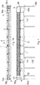
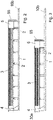
- the present patent application for industrial invention relates to a safety end piece for road barriers.
- the track (1) is provided in lower position with a set of posts (100) suitable for deeply penetrating the ground.
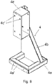
- the fourth part of the end section (T) consists in a column (4) suitable for fixing said first end (30a) of the beam (3) at the height of the first end (10a) of the track (1).
- the slider (5) has a base frame (50) with rectangular shape, formed of two transverse sections (50a, 50b) connected at right angle by two longitudinal sections (50c, 50d); it being provided that the two transverse sections (50a, 50b) are suitable for being exactly inserted between the two C-shaped guides (11a, 11b) of the track (1) with possibility of sliding freely.
- said partition (54) practically acts as deflector, it being capable of favoring the ejection towards one side of the slider (5) of the wooden chips produced by the blades (58a, 58b) that may be intercepted by the slider (5) during its forward travel along the track (1) and may otherwise interfere with the correct forward travel.
Landscapes
- Engineering & Computer Science (AREA)
- Architecture (AREA)
- Civil Engineering (AREA)
- Structural Engineering (AREA)
- Refuge Islands, Traffic Blockers, Or Guard Fence (AREA)
- Road Signs Or Road Markings (AREA)
Claims (10)
- Sicherheitsendstück für Straßenleitplanken, umfassend:- einen Balken (3) aus Brettschichtholz, der mit einem hinteren Endabschnitt (30a) und einem vorderen Endabschnitt (30b) versehen ist, in horizontaler Position oberhalb einer Schiene (1), die mit einem hinteren Endabschnitt (10a) und einem vorderen Endabschnitt (10b) versehen ist, mittels eines festen Tragmittels (4) getragen wird, das mit dem hinteren Endabschnitt (10a) der Schiene (1) und einer Mehrzahl von verschiebbaren Tragmitteln (2) entlang der Schiene (1) versehen ist, die geeignet sind, Punkte des Balkens (3) anzuziehen, die zwischen dem hinteren Endabschnitt (30a) und dem vorderen Endabschnitt (30b) des Balkens (3) liegen- einen Schieber (5), der geeignet ist, in den vorderen Endabschnitt (10b) der Schiene (1) mit freier Verschiebbarkeit eingesetzt zu werden und mit einem kastenförmigen Körper (CS) mit einer Zugangsmündung versehen ist, die geeignet ist, den vorderen Endabschnitt (30b) des Balkens (3) exakt aufzunehmen; wobei der kastenförmige Körper (CS) innen mit einer Mehrzahl von Klingen (58a, 59a) versehen ist, die hinter der Mündung angeordnet sind, wobei die Klingen (58a, 59a) geeignet sind, den Balken (3) längs zu schneiden und seine Länge schrittweise zu reduzieren, wenn der Schieber (5) einer Kraft ausgesetzt ist, die in der Lage ist, ihn in Richtung des hinteren Endabschnitts (10a) der Schiene (1) zu bewegen; wobei der Schieber (3) während der Vorschubbewegung schrittweise mit den verschiebbaren Tragmitteln (2) des Balkens (3) interferiert und die verschiebbaren Tragmittel (2) zwingt, sich rückwärts in Richtung des hinteren Endabschnitts (10a) der Schiene (1) zu bewegen.
- Endstück nach Anspruch 1, wobei die Schiene (1) aus einer ersten C-förmigen Führung (11a) und einer zweiten C-förmigen Führung (11b) gebildet ist, die identisch und parallel sind, deren Konkavitäten einander gegenüberliegen und die oberhalb einer Reihe von Traversen (11c) befestigt sind; wobei jede Traverse (11c) auch den Befestigungspunkt für einen Pfosten (100) darstellt, der geeignet ist, in den darunterliegenden Boden einzudringen.
- Endstück nach einem der vorstehenden Ansprüche, wobei der Balken (3) aus Brettschichtholz mit einem rechteckigen Abschnitt versehen ist, der sich vertikal erstreckt und durch eine erste vertikale Wand (3a), eine zweite vertikale Wand (3b), eine obere horizontale Wand (3c) und eine untere Wand (3d) definiert ist; und wobei die obere horizontale Wand (3c) und die untere horizontale Wand (3d) des Balkens (3) durch mittlere Längsnuten (24a, 24b) eingeschnitten sind.
- Endstück nach einem der vorstehenden Ansprüche, wobei die feststehenden Tragmittel des Balkens (3) aus einer Säule (4) bestehen, umfassend:- eine Basisplatte (4a), die geeignet ist, zwischen der ersten C-förmigen Führung (11a) und der zweiten C-förmigen Führung (11b) der Schiene (1) am hinteren Endabschnitt (10a) der Schiene (1) eingesetzt und befestigt zu werden;- einen Arm (4b), der vertikal aus der Platte (4a) vorsteht und geeignet ist, eine in Richtung der ersten C-förmigen Führung (11a) der Schiene (1) auskragende Hülse (4c) im Wesentlichen in der Mitte der Platte (4a) zu tragen, wobei die Hülse (4c) geeignet ist, den hinteren Endabschnitt (30a) des Balkens (3) exakt und fest aufzunehmen.
- Endstück nach Anspruch 4, wobei die Hülse (4c) der Säule (4) auf ihren vertikalen Wänden mit durchgehenden Löchern (4c') zum Einsetzen von Schrauben mit horizontaler Achse (V1) versehen ist, die geeignet sind, anschließend in entsprechende Löcher (31) einzugreifen, die am hinteren Endabschnitt (30a) des Balkens (3) herausgearbeitet sind.
- Endstück nach einem der vorstehenden Ansprüche, wobei die Platte (4c) an ihren Längskanten mit Löchern mit horizontaler Achse (4c') versehen ist, die geeignet sind, Schrauben mit horizontaler Achse (V2) aufzunehmen, die zuvor in entsprechende, auf der ersten C-förmigen Führung (11a) und der zweiten C-förmigen Führung (11b) in Höhe des hinteren Endabschnitts (10a) der Schiene (1) herausgearbeitete Löcher eingesetzt wurden.
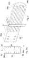
- Endstück nach einem der vorstehenden Ansprüche, wobei jedes der verschiebbaren Tragmittel des Balkens (3) aus einem verschiebbaren Tragmittel (2) besteht, umfassend:- einen Schlitten (20), der geeignet ist, verschiebbar zwischen die erste C-förmige Führung (11a) und die zweite C-förmige Führung (11b) der Schiene (1) eingesetzt zu werden- einen Ständer (21), der in dezentrierter Position nahe der ersten (11a) der beiden C-förmigen Führungen der Schiene (1) aus dem Schlitten (20) vorsteht- ein Paar von hakigen Bügeln (22, 23), die auf unterschiedlichen Höhen aus dem Ständer (21) in Richtung der zweiten (11b) der beiden C-förmigen Führungen der Schiene (1), im Wesentlichen auf der Mittellinie des Schlittens (20) vorstehen; wobei der obere Bügel (22) einen horizontalen Flügel (22a) umfasst, der am Ende mit einem nach unten gerichteten vertikalen Flügel (22b) verbunden ist und wobei der untere Bügel (23) einen horizontalen Flügel (23a) umfasst, der am Ende mit einem nach oben gerichteten vertikalen Flügel (23b) verbunden ist, der perfekt auf den vertikalen Flügel (22b) des oberen Bügels (22) ausgerichtet ist; wobei die horizontalen Flügel (23a, 23b) der Bügel (23, 23) geeignet sind, exakt gegen die obere horizontale Wand (3c) und die untere horizontale Wand (3d) des Balkens (3) zu interferieren, derart, dass die vertikalen Flügel (22b, 23b) in die Längsnuten (24a, 24b) einfallen, die jeweils auf der oberen horizontalen Wand (3c) und der unteren horizontalen Wand (3d) des Balkens (3) vorgesehen sind.
- Endstück nach einem der vorstehenden Ansprüche, wobei der Schieber (5) umfasst:- ein Untergestell (50), das geeignet ist, verschiebbar zwischen der ersten C-förmigen Führung (11a) und der zweiten C-förmigen Führung (11b) der Schiene (1) eingesetzt zu werden- ein Gestell (IN), das vertikal aus dem Untergestell (50) vorsteht- der kastenförmige Körper (CS) wird in horizontaler Position an der Spitze des vertikalen Gestells (IN) getragen und ist aus zwei Seitenflächen (56a, 56b) gebildet, die vorn durch ein Paneel (55) abgedeckt sind und hinten mit der Zugangsmündung (57) versehen sind, die geeignet ist, den vorderen Endabschnitt (30b) des Balkens (3) exakt aufzunehmen; wobei der kastenförmige Körper (CS) in einer Position zwischen den beiden Seitenflächen (56a, 56b) eine obere Öffnung (59a) und eine untere Öffnung (59) aufweist- eine obere Reihe von Klingen (58a) und eine untere Reihe von Klingen (58b), die zwischen den beiden Seitenflächen (56a, 56b) des kastenförmigen Körpers (CS) hinter der Mündung (57) befestigt und deshalb geeignet sind, mit dem Balken (3) zu interferieren, wenn der Schieber (5) seinen Rücklauf zum hinteren Endabschnitt (10a) der Schiene (1) beginnt und einen Längsschnitt in der Holzstruktur ausführt; wobei die obere Reihe von Klingen (58a) nach oben, in Richtung der oberen Öffnung (59a) des kastenförmigen Körpers (CS) gebogen ist, während die untere Reihe von Klingen (58b) nach unten, in Richtung der unteren Öffnung (59b) des kastenförmigen Körpers (CS) gebogen ist.
- Endstück nach Anspruch 8, wobei das Untergestell (50) des Schiebers (5) einen ersten Querabschnitt (50a) und einen zweiten Querabschnitt (50b) umfasst, die im rechten Winkel durch zwei Längsabschnitte (50c, 50d) verbunden sind und wobei das Gestell (IN) des Schiebers (5) vier vertikale Stäbe (50a', 50a", 50b', 50b") umfasst, die aus den vier Ecken des Gestells (5) vorstehen, wobei:- der erste vertikale Stab (50a') und der zweite vertikale Stab (50a") die gleiche Höhe aufweisen und aus dem ersten Querabschnitt (50a) des Untergestells (50) vorstehen, wobei sie auch dazu bestimmt sind, das Paneel (55) zu tragen- der dritte vertikale Stab (50b") und der vierte vertikale Stab (50b') aus dem zweiten Querabschnitt (50b) des Untergestells (50) vorstehen; wobei der dritte Stab (50b") die gleiche Höhe wie der erste Stab (50a') und der zweite Stab (50a") aufweist, während der vierte Stab (50b') im Wesentlichen halb so hoch ist und an dem dritten Stab (50b") mittels einer Traverse (50b"') verbunden und befestigt ist;und wobei der erste vertikale Stab (50a') und der vierte vertikale Stab (50b') die erste Seitenfläche (56) des kastenförmigen Körpers (CS) des Schiebers (5) tragen, während der zweite vertikale Stab (50a") und der dritte vertikale Stab (50b") die zweite Seitenfläche des kastenförmigen Körpers (CS) tragen, derart, dass der dritte vertikale Stab (5b") und der vierte vertikale Stab (5b') sich an den Seiten der Mündung (57) des kastenförmigen Körpers (CS) anordnen.
- Endstück nach einem der vorstehenden Ansprüche, wobei das Gestell (IN) des Schiebers (5) eine Längstrennwand (54) unter dem kastenförmigen Körper (CS) trägt, wobei die Längstrennwand (54) eine konvexe vertikale Kante (54a) aufweist, die zur ersten Seitenfläche (56a) des kastenförmigen Körpers (CS) in einer Position zwischen dem dritten vertikalen Stab (5b") und dem vierten vertikalen Stab (5b') gerichtet ist; und wobei der kastenförmige Körper (CS) einen Querflügel mit abfallendem Profil (53) aufweist, der oberhalb der Mündung (57) angeordnet ist.
Applications Claiming Priority (2)
| Application Number | Priority Date | Filing Date | Title |
|---|---|---|---|
| IT102019000002773A IT201900002773A1 (it) | 2019-02-26 | 2019-02-26 | Terminale di sicurezza per barriere stradali. |
| PCT/EP2020/050707 WO2020173612A1 (en) | 2019-02-26 | 2020-01-13 | Safety end piece for road barriers |
Publications (2)
| Publication Number | Publication Date |
|---|---|
| EP3931398A1 EP3931398A1 (de) | 2022-01-05 |
| EP3931398B1 true EP3931398B1 (de) | 2022-11-02 |
Family
ID=66641304
Family Applications (1)
| Application Number | Title | Priority Date | Filing Date |
|---|---|---|---|
| EP20700387.2A Active EP3931398B1 (de) | 2019-02-26 | 2020-01-13 | Sicherheitsendstück für strassensperren |
Country Status (9)
| Country | Link |
|---|---|
| US (1) | US11905670B2 (de) |
| EP (1) | EP3931398B1 (de) |
| ES (1) | ES2938073T3 (de) |
| FI (1) | FI3931398T3 (de) |
| IT (1) | IT201900002773A1 (de) |
| LT (1) | LT3931398T (de) |
| PL (1) | PL3931398T3 (de) |
| PT (1) | PT3931398T (de) |
| WO (1) | WO2020173612A1 (de) |
Families Citing this family (2)
| Publication number | Priority date | Publication date | Assignee | Title |
|---|---|---|---|---|
| WO2023178342A1 (en) * | 2022-03-18 | 2023-09-21 | Hill & Smith Inc. | Crash attenuator assemblies for decelerating vehicles |
| US20250171969A1 (en) * | 2023-11-28 | 2025-05-29 | Lindsay Transportation Solutions, Llc | Impact nose wedge |
Family Cites Families (18)
| Publication number | Priority date | Publication date | Assignee | Title |
|---|---|---|---|---|
| GB991522A (en) * | 1963-05-16 | 1965-05-12 | Fletcher Nicholson Platt | Crash barriers |
| US4674911A (en) * | 1984-06-13 | 1987-06-23 | Energy Absorption Systems, Inc. | Energy absorbing pneumatic crash cushion |
| EP0442830A1 (de) * | 1990-02-12 | 1991-08-21 | Compagnie Francaise Des Etablissements Gaillard | Leitplanke |
| US5172891A (en) * | 1992-01-27 | 1992-12-22 | Chen Chyi Bang | Safe road railing |
| US6293727B1 (en) * | 1997-06-05 | 2001-09-25 | Exodyne Technologies, Inc. | Energy absorbing system for fixed roadside hazards |
| US5957435A (en) * | 1997-07-11 | 1999-09-28 | Trn Business Trust | Energy-absorbing guardrail end terminal and method |
| US6444067B1 (en) * | 1999-12-03 | 2002-09-03 | Rick L. Bove | Recycling process for vehicle tires |
| WO2002066745A1 (en) * | 2001-02-19 | 2002-08-29 | Thorgeir Jonsson | Lateral load bearing structural cantilevered system such as highway guardrail and bridgerail systems |
| US6554256B2 (en) * | 2001-04-25 | 2003-04-29 | Icom Engineering, Inc. | Highway guardrail end terminal assembly |
| US20040086334A1 (en) * | 2002-10-31 | 2004-05-06 | Kamarata Dale E. | Multi-layered laminated posts and blocks for guardrail systems and method of making the same |
| US6962459B2 (en) * | 2003-08-12 | 2005-11-08 | Sci Products Inc. | Crash attenuator with cable and cylinder arrangement for decelerating vehicles |
| ES2279734B2 (es) * | 2007-01-19 | 2008-11-01 | Hierros Y Aplanaciones, S.A. (Hiasa) | Barrera de seguridad para carreteras mixta de madera y metal para contencion de impacto lateral de vehiculos, con cualidades esteticas y capacidad de contencion y redireccionamiento. |
| CN102015813B (zh) * | 2008-03-17 | 2013-05-22 | 巴特勒纪念研究院 | 回弹控制材料 |
| US9145943B2 (en) * | 2013-07-02 | 2015-09-29 | The Uab Research Foundation | Systems and methods for absorbing energy |
| US9051698B1 (en) * | 2014-06-19 | 2015-06-09 | Lindsay Transporation Solutions, Inc. | Crash attenuator apparatus |
| US10851503B2 (en) * | 2015-07-21 | 2020-12-01 | The Texas A&M University System | Tension end treatment for guardrail safety system |
| US9714493B1 (en) * | 2016-04-15 | 2017-07-25 | Lindsay Transportation Solutions, Inc. | Apparatus for absorbing energy when impacted by a vehicle |
| FR3097574B1 (fr) * | 2020-06-25 | 2023-03-31 | Soletanche Freyssinet | Structure d’absorption d’une énergie d’impact |
-
2019
- 2019-02-26 IT IT102019000002773A patent/IT201900002773A1/it unknown
-
2020
- 2020-01-13 FI FIEP20700387.2T patent/FI3931398T3/fi active
- 2020-01-13 LT LTEPPCT/EP2020/050707T patent/LT3931398T/lt unknown
- 2020-01-13 US US17/429,665 patent/US11905670B2/en active Active
- 2020-01-13 PT PT207003872T patent/PT3931398T/pt unknown
- 2020-01-13 EP EP20700387.2A patent/EP3931398B1/de active Active
- 2020-01-13 PL PL20700387.2T patent/PL3931398T3/pl unknown
- 2020-01-13 ES ES20700387T patent/ES2938073T3/es active Active
- 2020-01-13 WO PCT/EP2020/050707 patent/WO2020173612A1/en not_active Ceased
Also Published As
| Publication number | Publication date |
|---|---|
| FI3931398T3 (fi) | 2023-02-16 |
| LT3931398T (lt) | 2023-02-27 |
| ES2938073T3 (es) | 2023-04-04 |
| EP3931398A1 (de) | 2022-01-05 |
| PL3931398T3 (pl) | 2023-03-06 |
| PT3931398T (pt) | 2023-02-08 |
| US11905670B2 (en) | 2024-02-20 |
| IT201900002773A1 (it) | 2020-08-26 |
| US20220213658A1 (en) | 2022-07-07 |
| WO2020173612A1 (en) | 2020-09-03 |
Similar Documents
| Publication | Publication Date | Title |
|---|---|---|
| US6022003A (en) | Guardrail cutting terminal | |
| EP3931398B1 (de) | Sicherheitsendstück für strassensperren | |
| EP2077354B1 (de) | Anpralldämpfer | |
| US6416041B1 (en) | Guardrail system | |
| US7077442B2 (en) | Crash-box bumper mount | |
| KR20210122471A (ko) | 실탄의 탄두 회수 장치 | |
| US5348416A (en) | Gandy dancer: end piece for crash cushion or rail end treatment | |
| CN211057682U (zh) | 一种道路防撞护栏 | |
| EP0554864A1 (de) | Halbsteife Leitplanke für kontrollierte Dissipation der Aufprallenergie und Lage-Korrektur | |
| EP3660219B1 (de) | Endanschluss für eine schutzplanke | |
| KR101337567B1 (ko) | 충격 완화용 가드레일 | |
| CN108708333A (zh) | 一种易于拆装的高强度道路防护栏 | |
| KR101337569B1 (ko) | 가드레일의 완충용 엔드터미널 | |
| RU2791316C1 (ru) | Дорожный энергопоглощающий узел и дорожное фронтальное ограждение | |
| CN217810719U (zh) | 隧道口防撞安全装置 | |
| CN223118946U (zh) | 一种三波形防撞护栏板 | |
| KR102640400B1 (ko) | 도로용 충격흡수시설의 찢김식 충격에너지조절 및 흡수장치 | |
| KR102640394B1 (ko) | 차량용 충격흡수장치 | |
| EA003689B1 (ru) | Дорожное защитное ограждение | |
| EP1108090B1 (de) | Barriere zur kalibrierung der verzögerung von pkw während eines aufpralls | |
| CN222893560U (zh) | 一种低耗、防撞波形梁护栏 | |
| EA047190B1 (ru) | Дорожный энергопоглощающий узел и дорожное фронтальное ограждение | |
| WO2023055260A1 (ru) | Дорожный энергопоглощающий узел и дорожное фронтальное ограждение | |
| KR200285531Y1 (ko) | 폐타이어를 이용한 안전방호대 | |
| CN114622501A (zh) | 一种高速公路波形护栏及安装方法 |
Legal Events
| Date | Code | Title | Description |
|---|---|---|---|
| STAA | Information on the status of an ep patent application or granted ep patent |
Free format text: STATUS: UNKNOWN |
|
| STAA | Information on the status of an ep patent application or granted ep patent |
Free format text: STATUS: THE INTERNATIONAL PUBLICATION HAS BEEN MADE |
|
| PUAI | Public reference made under article 153(3) epc to a published international application that has entered the european phase |
Free format text: ORIGINAL CODE: 0009012 |
|
| STAA | Information on the status of an ep patent application or granted ep patent |
Free format text: STATUS: REQUEST FOR EXAMINATION WAS MADE |
|
| 17P | Request for examination filed |
Effective date: 20210803 |
|
| AK | Designated contracting states |
Kind code of ref document: A1 Designated state(s): AL AT BE BG CH CY CZ DE DK EE ES FI FR GB GR HR HU IE IS IT LI LT LU LV MC MK MT NL NO PL PT RO RS SE SI SK SM TR |
|
| DAV | Request for validation of the european patent (deleted) | ||
| GRAP | Despatch of communication of intention to grant a patent |
Free format text: ORIGINAL CODE: EPIDOSNIGR1 |
|
| STAA | Information on the status of an ep patent application or granted ep patent |
Free format text: STATUS: GRANT OF PATENT IS INTENDED |
|
| INTG | Intention to grant announced |
Effective date: 20220812 |
|
| GRAS | Grant fee paid |
Free format text: ORIGINAL CODE: EPIDOSNIGR3 |
|
| GRAA | (expected) grant |
Free format text: ORIGINAL CODE: 0009210 |
|
| STAA | Information on the status of an ep patent application or granted ep patent |
Free format text: STATUS: THE PATENT HAS BEEN GRANTED |
|
| AK | Designated contracting states |
Kind code of ref document: B1 Designated state(s): AL AT BE BG CH CY CZ DE DK EE ES FI FR GB GR HR HU IE IS IT LI LT LU LV MC MK MT NL NO PL PT RO RS SE SI SK SM TR |
|
| REG | Reference to a national code |
Ref country code: GB Ref legal event code: FG4D |
|
| REG | Reference to a national code |
Ref country code: CH Ref legal event code: EP Ref country code: AT Ref legal event code: REF Ref document number: 1528834 Country of ref document: AT Kind code of ref document: T Effective date: 20221115 |
|
| REG | Reference to a national code |
Ref country code: DE Ref legal event code: R096 Ref document number: 602020006052 Country of ref document: DE |
|
| REG | Reference to a national code |
Ref country code: IE Ref legal event code: FG4D |
|
| REG | Reference to a national code |
Ref country code: PT Ref legal event code: SC4A Ref document number: 3931398 Country of ref document: PT Date of ref document: 20230208 Kind code of ref document: T Free format text: AVAILABILITY OF NATIONAL TRANSLATION Effective date: 20230201 Ref country code: NL Ref legal event code: FP |
|
| REG | Reference to a national code |
Ref country code: EE Ref legal event code: FG4A Ref document number: E023038 Country of ref document: EE Effective date: 20230201 |
|
| REG | Reference to a national code |
Ref country code: ES Ref legal event code: FG2A Ref document number: 2938073 Country of ref document: ES Kind code of ref document: T3 Effective date: 20230404 |
|
| PG25 | Lapsed in a contracting state [announced via postgrant information from national office to epo] |
Ref country code: SE Free format text: LAPSE BECAUSE OF FAILURE TO SUBMIT A TRANSLATION OF THE DESCRIPTION OR TO PAY THE FEE WITHIN THE PRESCRIBED TIME-LIMIT Effective date: 20221102 Ref country code: NO Free format text: LAPSE BECAUSE OF FAILURE TO SUBMIT A TRANSLATION OF THE DESCRIPTION OR TO PAY THE FEE WITHIN THE PRESCRIBED TIME-LIMIT Effective date: 20230202 |
|
| PG25 | Lapsed in a contracting state [announced via postgrant information from national office to epo] |
Ref country code: RS Free format text: LAPSE BECAUSE OF FAILURE TO SUBMIT A TRANSLATION OF THE DESCRIPTION OR TO PAY THE FEE WITHIN THE PRESCRIBED TIME-LIMIT Effective date: 20221102 Ref country code: IS Free format text: LAPSE BECAUSE OF FAILURE TO SUBMIT A TRANSLATION OF THE DESCRIPTION OR TO PAY THE FEE WITHIN THE PRESCRIBED TIME-LIMIT Effective date: 20230302 Ref country code: HR Free format text: LAPSE BECAUSE OF FAILURE TO SUBMIT A TRANSLATION OF THE DESCRIPTION OR TO PAY THE FEE WITHIN THE PRESCRIBED TIME-LIMIT Effective date: 20221102 Ref country code: GR Free format text: LAPSE BECAUSE OF FAILURE TO SUBMIT A TRANSLATION OF THE DESCRIPTION OR TO PAY THE FEE WITHIN THE PRESCRIBED TIME-LIMIT Effective date: 20230203 |
|
| P01 | Opt-out of the competence of the unified patent court (upc) registered |
Effective date: 20230515 |
|
| PG25 | Lapsed in a contracting state [announced via postgrant information from national office to epo] |
Ref country code: SM Free format text: LAPSE BECAUSE OF FAILURE TO SUBMIT A TRANSLATION OF THE DESCRIPTION OR TO PAY THE FEE WITHIN THE PRESCRIBED TIME-LIMIT Effective date: 20221102 Ref country code: RO Free format text: LAPSE BECAUSE OF FAILURE TO SUBMIT A TRANSLATION OF THE DESCRIPTION OR TO PAY THE FEE WITHIN THE PRESCRIBED TIME-LIMIT Effective date: 20221102 Ref country code: DK Free format text: LAPSE BECAUSE OF FAILURE TO SUBMIT A TRANSLATION OF THE DESCRIPTION OR TO PAY THE FEE WITHIN THE PRESCRIBED TIME-LIMIT Effective date: 20221102 Ref country code: CZ Free format text: LAPSE BECAUSE OF FAILURE TO SUBMIT A TRANSLATION OF THE DESCRIPTION OR TO PAY THE FEE WITHIN THE PRESCRIBED TIME-LIMIT Effective date: 20221102 |
|
| REG | Reference to a national code |
Ref country code: DE Ref legal event code: R097 Ref document number: 602020006052 Country of ref document: DE |
|
| PG25 | Lapsed in a contracting state [announced via postgrant information from national office to epo] |
Ref country code: SK Free format text: LAPSE BECAUSE OF FAILURE TO SUBMIT A TRANSLATION OF THE DESCRIPTION OR TO PAY THE FEE WITHIN THE PRESCRIBED TIME-LIMIT Effective date: 20221102 Ref country code: AL Free format text: LAPSE BECAUSE OF FAILURE TO SUBMIT A TRANSLATION OF THE DESCRIPTION OR TO PAY THE FEE WITHIN THE PRESCRIBED TIME-LIMIT Effective date: 20221102 |
|
| PLBE | No opposition filed within time limit |
Free format text: ORIGINAL CODE: 0009261 |
|
| STAA | Information on the status of an ep patent application or granted ep patent |
Free format text: STATUS: NO OPPOSITION FILED WITHIN TIME LIMIT |
|
| 26N | No opposition filed |
Effective date: 20230803 |
|
| REG | Reference to a national code |
Ref country code: AT Ref legal event code: UEP Ref document number: 1528834 Country of ref document: AT Kind code of ref document: T Effective date: 20221102 |
|
| PG25 | Lapsed in a contracting state [announced via postgrant information from national office to epo] |
Ref country code: SI Free format text: LAPSE BECAUSE OF FAILURE TO SUBMIT A TRANSLATION OF THE DESCRIPTION OR TO PAY THE FEE WITHIN THE PRESCRIBED TIME-LIMIT Effective date: 20221102 |
|
| PGFP | Annual fee paid to national office [announced via postgrant information from national office to epo] |
Ref country code: DE Payment date: 20240129 Year of fee payment: 5 |
|
| PGFP | Annual fee paid to national office [announced via postgrant information from national office to epo] |
Ref country code: BE Payment date: 20240125 Year of fee payment: 5 |
|
| PG25 | Lapsed in a contracting state [announced via postgrant information from national office to epo] |
Ref country code: BG Free format text: LAPSE BECAUSE OF FAILURE TO SUBMIT A TRANSLATION OF THE DESCRIPTION OR TO PAY THE FEE WITHIN THE PRESCRIBED TIME-LIMIT Effective date: 20221102 |
|
| PG25 | Lapsed in a contracting state [announced via postgrant information from national office to epo] |
Ref country code: BG Free format text: LAPSE BECAUSE OF FAILURE TO SUBMIT A TRANSLATION OF THE DESCRIPTION OR TO PAY THE FEE WITHIN THE PRESCRIBED TIME-LIMIT Effective date: 20221102 |
|
| PG25 | Lapsed in a contracting state [announced via postgrant information from national office to epo] |
Ref country code: CY Free format text: LAPSE BECAUSE OF FAILURE TO SUBMIT A TRANSLATION OF THE DESCRIPTION OR TO PAY THE FEE WITHIN THE PRESCRIBED TIME-LIMIT; INVALID AB INITIO Effective date: 20200113 |
|
| REG | Reference to a national code |
Ref country code: DE Ref legal event code: R119 Ref document number: 602020006052 Country of ref document: DE |
|
| PG25 | Lapsed in a contracting state [announced via postgrant information from national office to epo] |
Ref country code: HU Free format text: LAPSE BECAUSE OF FAILURE TO SUBMIT A TRANSLATION OF THE DESCRIPTION OR TO PAY THE FEE WITHIN THE PRESCRIBED TIME-LIMIT; INVALID AB INITIO Effective date: 20200113 |
|
| PG25 | Lapsed in a contracting state [announced via postgrant information from national office to epo] |
Ref country code: DE Free format text: LAPSE BECAUSE OF NON-PAYMENT OF DUE FEES Effective date: 20250801 |
|
| PG25 | Lapsed in a contracting state [announced via postgrant information from national office to epo] |
Ref country code: BE Free format text: LAPSE BECAUSE OF NON-PAYMENT OF DUE FEES Effective date: 20250131 |
|
| REG | Reference to a national code |
Ref country code: BE Ref legal event code: MM Effective date: 20250131 |
|
| PG25 | Lapsed in a contracting state [announced via postgrant information from national office to epo] |
Ref country code: TR Free format text: LAPSE BECAUSE OF FAILURE TO SUBMIT A TRANSLATION OF THE DESCRIPTION OR TO PAY THE FEE WITHIN THE PRESCRIBED TIME-LIMIT Effective date: 20221102 |
|
| PGFP | Annual fee paid to national office [announced via postgrant information from national office to epo] |
Ref country code: LT Payment date: 20251223 Year of fee payment: 7 |
|
| PGFP | Annual fee paid to national office [announced via postgrant information from national office to epo] |
Ref country code: PT Payment date: 20251223 Year of fee payment: 7 |
|
| PGFP | Annual fee paid to national office [announced via postgrant information from national office to epo] |
Ref country code: FI Payment date: 20251222 Year of fee payment: 7 |
|
| PGFP | Annual fee paid to national office [announced via postgrant information from national office to epo] |
Ref country code: PL Payment date: 20251219 Year of fee payment: 7 |
|
| REG | Reference to a national code |
Ref country code: CH Ref legal event code: U11 Free format text: ST27 STATUS EVENT CODE: U-0-0-U10-U11 (AS PROVIDED BY THE NATIONAL OFFICE) Effective date: 20260201 |
|
| PGFP | Annual fee paid to national office [announced via postgrant information from national office to epo] |
Ref country code: NL Payment date: 20260122 Year of fee payment: 7 Ref country code: LU Payment date: 20260122 Year of fee payment: 7 |
|
| PGFP | Annual fee paid to national office [announced via postgrant information from national office to epo] |
Ref country code: GB Payment date: 20260126 Year of fee payment: 7 |
|
| PGFP | Annual fee paid to national office [announced via postgrant information from national office to epo] |
Ref country code: ES Payment date: 20260210 Year of fee payment: 7 Ref country code: MC Payment date: 20260120 Year of fee payment: 7 |
|
| PGFP | Annual fee paid to national office [announced via postgrant information from national office to epo] |
Ref country code: IE Payment date: 20260120 Year of fee payment: 7 |
|
| PGFP | Annual fee paid to national office [announced via postgrant information from national office to epo] |
Ref country code: AT Payment date: 20260119 Year of fee payment: 7 |
|
| PGFP | Annual fee paid to national office [announced via postgrant information from national office to epo] |
Ref country code: IT Payment date: 20251204 Year of fee payment: 7 |
|
| PGFP | Annual fee paid to national office [announced via postgrant information from national office to epo] |
Ref country code: FR Payment date: 20260126 Year of fee payment: 7 |
|
| PGFP | Annual fee paid to national office [announced via postgrant information from national office to epo] |
Ref country code: CH Payment date: 20260201 Year of fee payment: 7 |
|
| PGFP | Annual fee paid to national office [announced via postgrant information from national office to epo] |
Ref country code: MT Payment date: 20260127 Year of fee payment: 7 |
|
| PGFP | Annual fee paid to national office [announced via postgrant information from national office to epo] |
Ref country code: LV Payment date: 20260122 Year of fee payment: 7 Ref country code: EE Payment date: 20260127 Year of fee payment: 7 |