EP3931366B1 - Processing line for depositing thin-film coatings - Google Patents
Processing line for depositing thin-film coatings Download PDFInfo
- Publication number
- EP3931366B1 EP3931366B1 EP20706535.0A EP20706535A EP3931366B1 EP 3931366 B1 EP3931366 B1 EP 3931366B1 EP 20706535 A EP20706535 A EP 20706535A EP 3931366 B1 EP3931366 B1 EP 3931366B1
- Authority
- EP
- European Patent Office
- Prior art keywords
- processing
- carriage
- processing line
- drums
- carriages
- Prior art date
- Legal status (The legal status is an assumption and is not a legal conclusion. Google has not performed a legal analysis and makes no representation as to the accuracy of the status listed.)
- Active
Links
Images




Classifications
-
- C—CHEMISTRY; METALLURGY
- C23—COATING METALLIC MATERIAL; COATING MATERIAL WITH METALLIC MATERIAL; CHEMICAL SURFACE TREATMENT; DIFFUSION TREATMENT OF METALLIC MATERIAL; COATING BY VACUUM EVAPORATION, BY SPUTTERING, BY ION IMPLANTATION OR BY CHEMICAL VAPOUR DEPOSITION, IN GENERAL; INHIBITING CORROSION OF METALLIC MATERIAL OR INCRUSTATION IN GENERAL
- C23C—COATING METALLIC MATERIAL; COATING MATERIAL WITH METALLIC MATERIAL; SURFACE TREATMENT OF METALLIC MATERIAL BY DIFFUSION INTO THE SURFACE, BY CHEMICAL CONVERSION OR SUBSTITUTION; COATING BY VACUUM EVAPORATION, BY SPUTTERING, BY ION IMPLANTATION OR BY CHEMICAL VAPOUR DEPOSITION, IN GENERAL
- C23C14/00—Coating by vacuum evaporation, by sputtering or by ion implantation of the coating forming material
- C23C14/22—Coating by vacuum evaporation, by sputtering or by ion implantation of the coating forming material characterised by the process of coating
- C23C14/50—Substrate holders
- C23C14/505—Substrate holders for rotation of the substrates
-
- C—CHEMISTRY; METALLURGY
- C23—COATING METALLIC MATERIAL; COATING MATERIAL WITH METALLIC MATERIAL; CHEMICAL SURFACE TREATMENT; DIFFUSION TREATMENT OF METALLIC MATERIAL; COATING BY VACUUM EVAPORATION, BY SPUTTERING, BY ION IMPLANTATION OR BY CHEMICAL VAPOUR DEPOSITION, IN GENERAL; INHIBITING CORROSION OF METALLIC MATERIAL OR INCRUSTATION IN GENERAL
- C23C—COATING METALLIC MATERIAL; COATING MATERIAL WITH METALLIC MATERIAL; SURFACE TREATMENT OF METALLIC MATERIAL BY DIFFUSION INTO THE SURFACE, BY CHEMICAL CONVERSION OR SUBSTITUTION; COATING BY VACUUM EVAPORATION, BY SPUTTERING, BY ION IMPLANTATION OR BY CHEMICAL VAPOUR DEPOSITION, IN GENERAL
- C23C14/00—Coating by vacuum evaporation, by sputtering or by ion implantation of the coating forming material
- C23C14/22—Coating by vacuum evaporation, by sputtering or by ion implantation of the coating forming material characterised by the process of coating
- C23C14/56—Apparatus specially adapted for continuous coating; Arrangements for maintaining the vacuum, e.g. vacuum locks
- C23C14/564—Means for minimising impurities in the coating chamber such as dust, moisture, residual gases
- C23C14/566—Means for minimising impurities in the coating chamber such as dust, moisture, residual gases using a load-lock chamber
-
- C—CHEMISTRY; METALLURGY
- C23—COATING METALLIC MATERIAL; COATING MATERIAL WITH METALLIC MATERIAL; CHEMICAL SURFACE TREATMENT; DIFFUSION TREATMENT OF METALLIC MATERIAL; COATING BY VACUUM EVAPORATION, BY SPUTTERING, BY ION IMPLANTATION OR BY CHEMICAL VAPOUR DEPOSITION, IN GENERAL; INHIBITING CORROSION OF METALLIC MATERIAL OR INCRUSTATION IN GENERAL
- C23C—COATING METALLIC MATERIAL; COATING MATERIAL WITH METALLIC MATERIAL; SURFACE TREATMENT OF METALLIC MATERIAL BY DIFFUSION INTO THE SURFACE, BY CHEMICAL CONVERSION OR SUBSTITUTION; COATING BY VACUUM EVAPORATION, BY SPUTTERING, BY ION IMPLANTATION OR BY CHEMICAL VAPOUR DEPOSITION, IN GENERAL
- C23C14/00—Coating by vacuum evaporation, by sputtering or by ion implantation of the coating forming material
- C23C14/22—Coating by vacuum evaporation, by sputtering or by ion implantation of the coating forming material characterised by the process of coating
- C23C14/56—Apparatus specially adapted for continuous coating; Arrangements for maintaining the vacuum, e.g. vacuum locks
- C23C14/568—Transferring the substrates through a series of coating stations
-
- C—CHEMISTRY; METALLURGY
- C23—COATING METALLIC MATERIAL; COATING MATERIAL WITH METALLIC MATERIAL; CHEMICAL SURFACE TREATMENT; DIFFUSION TREATMENT OF METALLIC MATERIAL; COATING BY VACUUM EVAPORATION, BY SPUTTERING, BY ION IMPLANTATION OR BY CHEMICAL VAPOUR DEPOSITION, IN GENERAL; INHIBITING CORROSION OF METALLIC MATERIAL OR INCRUSTATION IN GENERAL
- C23C—COATING METALLIC MATERIAL; COATING MATERIAL WITH METALLIC MATERIAL; SURFACE TREATMENT OF METALLIC MATERIAL BY DIFFUSION INTO THE SURFACE, BY CHEMICAL CONVERSION OR SUBSTITUTION; COATING BY VACUUM EVAPORATION, BY SPUTTERING, BY ION IMPLANTATION OR BY CHEMICAL VAPOUR DEPOSITION, IN GENERAL
- C23C16/00—Chemical coating by decomposition of gaseous compounds, without leaving reaction products of surface material in the coating, i.e. chemical vapour deposition [CVD] processes
- C23C16/44—Chemical coating by decomposition of gaseous compounds, without leaving reaction products of surface material in the coating, i.e. chemical vapour deposition [CVD] processes characterised by the method of coating
- C23C16/458—Chemical coating by decomposition of gaseous compounds, without leaving reaction products of surface material in the coating, i.e. chemical vapour deposition [CVD] processes characterised by the method of coating characterised by the method used for supporting substrates in the reaction chamber
-
- C—CHEMISTRY; METALLURGY
- C23—COATING METALLIC MATERIAL; COATING MATERIAL WITH METALLIC MATERIAL; CHEMICAL SURFACE TREATMENT; DIFFUSION TREATMENT OF METALLIC MATERIAL; COATING BY VACUUM EVAPORATION, BY SPUTTERING, BY ION IMPLANTATION OR BY CHEMICAL VAPOUR DEPOSITION, IN GENERAL; INHIBITING CORROSION OF METALLIC MATERIAL OR INCRUSTATION IN GENERAL
- C23C—COATING METALLIC MATERIAL; COATING MATERIAL WITH METALLIC MATERIAL; SURFACE TREATMENT OF METALLIC MATERIAL BY DIFFUSION INTO THE SURFACE, BY CHEMICAL CONVERSION OR SUBSTITUTION; COATING BY VACUUM EVAPORATION, BY SPUTTERING, BY ION IMPLANTATION OR BY CHEMICAL VAPOUR DEPOSITION, IN GENERAL
- C23C16/00—Chemical coating by decomposition of gaseous compounds, without leaving reaction products of surface material in the coating, i.e. chemical vapour deposition [CVD] processes
- C23C16/44—Chemical coating by decomposition of gaseous compounds, without leaving reaction products of surface material in the coating, i.e. chemical vapour deposition [CVD] processes characterised by the method of coating
- C23C16/54—Apparatus specially adapted for continuous coating
Definitions
- the invention relates to the field of mass production technological equipment for surface treatment, and particularly, to vacuum processing equipment intended for depositing thin-film coatings with specified optical, electrical and other characteristics.
- a method and device for magnetron sputtering of thin-film coatings onto substrates are known (see [1] US 4,851,095, Int. Cl. C 23 C 14/00, publication date: July 25, 1989 ), in which said substrates are mounted onto the substrate support embodied in the form of a rotating cylindrical drum.
- the sputtering of the coatings onto the substrates is carried out by the working devices located within a vacuum chamber surrounding the drum.
- the uniformity of the coating in one direction is ensured by rotating the drum, and in the second direction - by using linear technological devices.
- the method consists in placing the substrates on a flat vertical carriage-carrier moving within a linear-type technological device.
- the processing line includes positioned in series lock-chamber, processing chamber containing the technological device, outlet buffer chamber and a flat substrate support capable of moving along the chambers.
- An in-line type equipment is known from the prior art, which is used to treat flat substrates.
- an automated setup for forming thin-film coatings of nanosized thickness by using a molecular layering method is known, where substrates are mounted onto the carriage-carrier, which moves along the processing stages arranged in series.
- this device same as current in-line type equipment, has disadvantages, which include low operational reliability caused by the fact that secure attachment of the substrates depends on how smooth the transport system is, and high cost associated with the use of complicated control and adjustment systems to ensure the required uniformity of the deposited coatings.
- This method is implemented in the processing line for depositing thin-film coatings comprising lock and buffer chambers, and at least one processing chamber containing a technological device; substrate supports located on the carriages capable of passing sequentially through the chambers; and a transport system, wherein each substrate support is embodied in the form of a rotating drum installed on the carriage coaxially to the movement direction thereof, while the drums are configured to rotate at a constant angular velocity and carriages are configured to move at a constant linear velocity while ensuring that each point of the drum surface will complete at least two full revolutions when passing through a processing zone of the technological device.
- a disadvantage of the prototype is that some technological devices, which can be located inside the processing chamber, and particularly, evaporators, which can constitute a considerable part of these technological devices, cause an inefficient consumption of the material precipitating onto the substrates in the form of the required thin-film coatings. A part of the material precipitates onto the walls of the chamber and other elements.
- an evaporator embodied in the form of a crucible containing the material for precipitation. Regardless of the method of heating of the crucible and/or the material inside the crucible, precipitation of the film on the substrate located in front of the crucible will follow the cosine law (see [4] Fig. 1 ). A part of the evaporated material will miss the substrate.
- US 2016/333467 discloses a processing line for depositing thin-film coatings comprising at least one lock chamber, at least one buffer chamber and at least one processing chamber containing technological devices, as well as a substrate support located on carriages configured to pass sequentially through the chambers, wherein 1 of the technological devices is adapted to deposit material on the surface of the substrate and one further device is adapted to further process the deposited material, the substrate holder are made as the rotating drum which moves through the processing chamber parallel to the rotation axis of the drum.
- the objective of the proposed invention is to eliminate the disadvantages of the analogs and prototype by creating a high-performance equipment, capable of depositing onto substrates complex coatings, such as metal-dielectric and composite metal-dielectric coatings.
- Technical result of the proposed invention consists in increased productivity and efficiency of material consumption when precipitating thin-film coatings, as well as in possibility of implementing various schemes of depositing thin-film coatings in one line.
- the technological device may be e.g. a source of depositing material such as vaporizers or preferably in the form of a magnetron or any other source of e.g. mist, vapor or influenced particles as layering material.
- the technological device may also be e.g. any curing and/or hardening and/or drying device such as a high density plasma source, means for oxidation of deposited material on the surface including any means that lead to a formation of a chemical compound including reaction with e.g. oxygen, nitrogen, selenium.
- the technological device may be any means that as necessary for applying or curing or participating in the formation of deposited layer structure on a treated surface.
- the proposed processing line comprises at least one lock-chamber, at least one buffer chamber, and at least one processing chamber containing technological devices, as well as substrate supports, and a transport system with drive rollers and high-vacuum pumps.
- Substrate support (1) is embodied in the form of a rotating drum installed in the bearings on carriage (2).
- the carriages are configured to pass from one chamber to another. However, within a chamber, in particular within the processing chamber the at least one carriage can be moved at a constant speed from one end of the chamber to the opposite end.
- two rotating drums are mounted next to each other on each carriage, so that their axes are parallel, i.e. the drums are installed in such a way that the generator lines thereof are parallel.
- a so-formed pair of drums is installed on the carriage coaxially to its moving direction and is preferably configured to rotate at a constant angular velocity, while the carriages are configured to move forward at a constant linear velocity.
- the drums may have the same or different diameter. Additionally, the drums are capable of rotating in the same or opposite directions. The drums are positioned in such a way that the distance between their axes is equal to the sum of radiuses of the drums, while ensuring a minimum clearance between them.
- Several carriages can be moved together through the chamber wherein the carriages are e.g. aligned parallel to each other or behind each other.
- Substrates (3) are preferably mounted to the drum surface by any known method of securing them reliably during the rotation and movement of the drums.
- the carriage is provided with guides (4) installed on the posts (not shown of the drawing) made of a dielectric material.
- the carriage guides are installed on the drive rollers of the transport system.
- the carriages with the drums move through the chambers sequentially, thus one after another.
- the first element of the detachable coupling (5) represents a hollow cylinder made of a soft magnetic material with magnets (11) mounted on the internal surface thereof.
- the magnets are installed with alternating polarity in the directions of magnetization shown in the drawing.
- the mating element (6) of the magnetic coupling represents a cylinder made of a soft magnetic material with magnets (12) mounted on the surface thereof, the number of which matches the number of the magnets of the first element.
- the magnets are installed with alternating polarity in the directions of magnetization shown in the drawing.
- There is a 5 mm gap between the magnets of the first (5) and mating (6) elements to ensure no touching when the coupling slips due to an imprecise joining of the substrate supports (1).
- a direct-acting electric drive is used.
- the rotor of electric drive (7) is preferably formed by a ring-type magnetic circuit with magnets mounted thereon.
- the stator of electric drive (8) and the control unit are mounted on the carriage frame.
- the electric drive is powered by direct current supplied through the linear guides of carriage (4).
- the linear guides are secured on the isolating posts of the carriage. The power to the linear guides is fed through the rollers of the transport system.
- the technological devices are preferably installed along the path of the substrate supports, and the processing zone is defined as the area along the path of the substrate supports, within which the technological device is located, and within which the majority of the material deposited by this device (above 90%) hits the substrate support.
- the processing zone is defined as the area along the path of the substrate supports, within which the technological device is located, and within which the majority of the material deposited by this device (above 90%) hits the substrate support.
- several technological devices intended for depositing the same material which form partially or completely overlapping processing zones, are considered as one technological device.
- several technological devices participating in depositing a layer can be installed around the substrate supports thus, around the drums along their movement path within the processing chamber.
- Technological devices for depositing materials can also be realized in the form of evaporators, electron beam evaporators (EBE), magnetrons, ionic sources and any other known technological devices especially for deposition of coating material.
- the processing line comprises at least one lock-chamber, at least one buffer chamber, and at least one processing chamber containing technological devices; as well as preferably substrate supports and/or a transport system with drive rollers and/or high-vacuum pumps.
- substrate support (1) is embodied in the form of a rotating drum which is installed in the bearings on carriage (9).
- an additional second carriage (10) is installed with one rotating drum mounted on each carriage.
- Each drum is installed on a carriage coaxially to its moving direction and is configured to rotate at a constant angular velocity, while the carriages are configured to move forward at a constant linear velocity while preferably ensuring that each point of the drum surface will complete at least two full revolutions when passing through a processing zone of the technological devices.
- the drums are preferably positioned in such a way that the distance between the axes thereof is equal to the sum of radiuses of the drums, while ensuring a minimum clearance between them such that the drums do not touch each other. Additionally, the drums are preferably capable of rotating in the same or opposite directions.
- Substrates (3) are mounted to the drum surface by any known method of securing them reliably during the rotation and movement of the drums.
- the carriage is provided with guides (4) installed on the posts (not shown of the drawing) made of a dielectric material.
- the carriage guides are installed on the drive rollers of the transport system.
- Carriages that are installed/arranged next to each other, i.e., substantially in parallel, are configured to move forward in the same or opposite directions, i.e., towards each other, e.g. on individual tracks for each carriage.
- the tracks might also be connected e.g. such that on one track a carriage(s) might move in one direction through the processing zone and on the other track the carriage might move on the other track in the opposite direction though the processing zone.
- the two track may also be embodies as a single track that is bent or redirected such that at least two parts of the track are oriented parallel to each other.
- a carriage moving along such track has at least twice the movement distance within the processing zone compared to a single movement though the processing zone which allows for much more surface treatment which in the same length of a processing zone.
- such setup allows to pass through the processing zone more than one carriage at a time even with only one airlock on one side of the processing zone since the way into the processing zone and out of the processing zone are preferably provided on separate tracks or separate parts of the track.
- the inventive setup allows for a much higher throughput of carriag-es/drums even with only one airlock/opening compared to a setup known in the prior art.
- the carriages with the drums move through the chambers preferably sequentially, thus one after another.
- the drum rotation is preferably performed by direct-acting electric drive powered through the linear guides of the carriage.
- the technological devices are installed along the path of the substrate supports and/or the processing zone is defined as the area along the path of the substrate supports, within which the technological device(s) is located, and within which the majority of the material deposited by this device (above 90%) hits the substrate support.
- the processing zone is defined as the area along the path of the substrate supports, within which the technological device(s) is located, and within which the majority of the material deposited by this device (above 90%) hits the substrate support.
- several technological devices intended for depositing the same material which form partially or completely overlapping processing zones, are considered as one technological device.
- several technological devices participating in depositing a layer can be installed around the substrate supports.
- Technological devices for depositing materials can be realized in the form of evaporators, electron beam evaporators (EBE), magnetrons, ionic sources and any other known technological devices.
- the line may operate as follows.
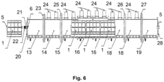
- Supports (1) with the substrates mounted thereon are supplied to a low-vacuum inlet lock-chamber (13), after which the lock-chamber door (20) is closed. After the door closing, the supports may be moved back, and their detachable couplings (5) may engage with the mating parts of the couplings (6) mounted to the shafts of the vacuum rotary-motion feedthroughs of the motors (21) which may be installed on the lock-chamber door and/or be activated by the electric motors (22). In this case, it is possible to use a single electric motor, or several electric motors, one per each shaft.
- the electric motor spins up the substrate supports to a preset rotation velocity, while the lock-chamber is being evacuated to 10-20 Pa.
- the transport lock (23) After evacuating the low-vacuum inlet lock-chamber and spinning up the drums, the transport lock (23) opens, the carriage carriers move to the high-vacuum inlet lock-chamber (14), and the lock (23) is closed.
- the high-vacuum lock-chamber may be provided with turbomolecular pumps (24), and maybe evacuated to ⁇ 0.01 Pa.
- turbomolecular pumps 24
- a controlled filling of the lock-chamber with gas of controlled composition can be used, while monitoring the pressure level and ensuring its equality to the pressure inside the processing chamber is possible.
- the transport lock (25) may open, the substrate supports may move to the inlet buffer chamber (15), and the lock (25) may be closed.
- the substrate supports In the buffer chamber, the substrate supports may be slowed down to the processing velocity value and may be joined with the substrate supports supplied to the processing line at the previous step.
- the magnetic couplings of the substrate supports may engage, and rotation of the supplied substrate support may be synchronized with that of substrate supports (1) passing through the processing chamber.
- the rollers of the transport system may be energized, so that electric motors of the substrate supports can sustain rotation of their drums.
- the coating When passing through the processing chamber(s) (16), the coating is deposited onto the substrates. While the substrates are being treated (when passing through the processing zone), the drums may rotate and may move steadily along their axes. The substrate supports preferably move through the processing zones at a minimum clearance between them.
- the ratio between the linear movement velocity and rotation velocity of the substrate supports is preferably set such that each point of the surface of the substrate supports would complete at least two full revolutions when passing through the processing zone.
- the displacement pitch during one revolution is preferably rather small and allows providing high uniformity of the deposited coatings regardless of the utilized types of technological devices, including linear and point-type devices.
- the objective of ensuring the required rotation velocity of the substrate supports during processing while maintaining concurrent linear movement can be achieved by one of the following methods:
- metal-dielectric and composite metal-dielectric coatings in addition to conventional devices for in-line equipment, one of the following methods can be used, namely, multiple deposition of thin metallic or unoxidized layers with subsequent oxidation.
- oxidation means any reaction leading to the formation of a chemical compound, including reactions with oxygen, nitrogen, selenium, etc.
- a special processing zone is formed, within which the substrate support is surrounded by the technological devices for depositing one or several metals, and a technological device for performing oxidation, which represents a source of activated jet gas (for example, a plasma source, wherein the source can be any known plasma-generating device) ( Fig. 7-11 ).
- a source of activated jet gas for example, a plasma source, wherein the source can be any known plasma-generating device
- the technological devices for depositioning of the material on the surface (on/of the drum) to be layered may be located within the processing zone such that one side of the drum/carriage passes by that technological device e.g. on the bottom part of said processing zone.
- hardening, curing or oxidation of the depositioned material may be located within the processing zone such that the opposite side of the drum compared to the side of the drum that is oriented towards the technological devices for depositioning of the material on the surface to be layered is treated.
- the devices may be provided on opposite sides withing the processing zone.
- Such technological device may be e.g. located in a top part of said processing zone, preferably above the drums which passes by said technological devices.
- a 1 st side of the drum surface preferably along a longitudinal axis of the drum, is orientated towards technological devices for depositioning and a 2 nd side of the drum surface, preferably also along a longitudinal axis of the drum, is orientated towards technological devices for further treatment e.g. hardening, curing or oxidation of the depositioned material.
- 1 st and 2 nd side of the drum surface is a rather dynamic definition since the drum is preferably constantly rotating within the processing zone. However, at each point and time there's two opposite sides of the rotating drum whereby each side is orientated towards 1 of the 2 preliminarily explained technological devices.
- the drum is passed through a processing zone within the processing chamber wherein the processing zone is defined by at least 2 technological devices which are located such that a rotating drum passing through that processing zone will be treated by those technological devices from different angles but preferably simultaneously.
- This angle between the devices along a longitudinal axis of movement of the carriage/drum within the processing chamber may be 180° thus treatment from opposite sides. However, treatment may also be provided from a different angle e.g.
- the orientation of the technological devices can rather be in the form of a triangle, square, pentagon or any regular or irregular geometrical arrangement through which the rotating drum passes.
- high-vacuum evacuation equipment may be installed to ensure gas separation between the technological device for performing e.g. oxidation and technological devices for e.g. depositing materials. This provides a stable and high-performance operation of the technological devices for depositing materials.
- gas separation between the technological devices can be provided between all technological devices.
- the gas separation is provided between the means for depositioning of coating material and the means for processing the depositioned material on the surface of the drum.
- each point of the processed surface sequentially may pass multiple times by the technological devices for depositing materials, where a super-thin layer of material is deposited, and by the technological device of performing e.g. oxidation, where this layer is preferably completely oxidized of further treated (cured, hardened,...) in another suitable way.
- the treated surface becomes evenly coated with metal-dielectric or composite metal-dielectric coating having a specified composition.
- Technological devices can deposit same or different materials. In the latter case, the rates of material deposition can be set to be different to ensure the required composition of the coating.
- the substrate supports After passing through the processing chambers (16), the substrate supports exit into the outlet buffer chamber (17).
- the transport lock (26) may open, substrate supports may accelerate accelerated while preferably increasing the distance from the supports that follow, and move to the high-vacuum outlet lock-chamber (18).
- lock (26) preferably closes
- transport lock (27) preferably opens, and the substrate supports move to the low-vacuum outlet lock-chamber (19), where the mating elements of the magnetic couplings of the substrate supports may be joined with the first elements of magnetic couplings (5) mounted on a door.
- the elements of magnetic couplings (5) may be secured on the shafts, the rotation of which is inhibited due to friction.
- the lock (27) closes, the chamber is filled with dried air, and the pressure rises to atmospheric. At this time, due to braking of the coupling (5), the drums of the substrate supports come to a stop.
- the chamber door (28) opens, and the substrate support comes out of the processing line.
- the drums are preferably configured to facilitate a concentric rotation of the substrates or flipping of the substrates in one or several given positions along the processing line.
- a modification of the line which has no outlet lock and buffer chambers, is possible, which can be achieved by installing e.g. two carriages next to each other, i.e. substantially, in parallel, and moving the carriages forward in e.g. opposite directions (towards each other) e.g. on separate tracks so they can pass by each other
- the inlet lock-chamber may also be used as an outlet chamber, i.e., the carriages carrying substrates mounted to the drums move until the end of the processing chamber, and then may turn around (preferably switched to a counter path) and go back to the lock-chamber. Turning around of the carriages (e.g. switching them to a counter path) may be performed without exposure to the atmosphere. Due to such realization of the invention, it becomes possible to reduce the number of chambers in the system, and also save place inside the clean room. in case the drums move towards each other, it is possible to deposit several coatings, i.e., when moving in one direction, one coating is deposited, and when moving in the reverse direction, another coating can be deposited.
- the drums move towards each other, it is possible to deposit coating onto both sides of the substrate, i.e., when moving in one direction, the coating is deposited to side A, and when moving in the reverse direction, the coating is deposited to side B.
- the drums may be configured to allow concentric rotation of the substrates or flipping of the substrates in one or several given positions along the processing line to deposit coatings onto both sides of the substrate.
- the proposed (two-drum) system also allows realizing schemes for depositing complex single- and multi-component coatings in a single or multiple layers, including coatings in which different layers have different compositions, structure and properties, by utilizing different arrangement of the technological devices in the processing chamber.
- a technological device for depositioning of layering material e.g. an evaporator or magneton (29) is preferably positioned at the bottom of the processing chamber such that the carriage which moves by is orientated such that the technological device is located between the drums, while the technological device for further processing of the depositioned layer e.g. the plasma source (30) is positioned e.g. at the top the processing chamber such that the carriage which moves by is orientated (relative orientation) such that the technological device for the processing is located between the drums ( Fig. 7 ).
- the technological device for further processing of the depositioned layer e.g. the plasma source (30) is positioned e.g. at the top the processing chamber such that the carriage which moves by is orientated (relative orientation) such that the technological device for the processing is located between the drums ( Fig. 7 ).
- Such arrangement allows for a much higher depositioning yield with respect to the e.g. evaporated material compared to known setups.
- any known e.g. plasma-generating device can be used as a technological device for further processing of the depositioned layer.
- evaporators and/or magnetrons can be installed along the processing chamber also in different angles with respect to the carriage with the drums passing by. They may contain the same or different materials to form composite or multilayer coatings.
- Two or more technological devices for depositioning of a layer material may also be provided at different angles in the same or different (longitudinal) position along the travelling route of the carriage within the processing chamber.
- a quartz monitoring head may be placed next to the evaporators.
- the processing zone may be divided in such a way that the mutual effect of the reactive zone (further processing of the depositioned material) and material deposition zone could be eliminated, even if they are provided in the same (longitudinal) position along the chillout travelling route of the carriage within the processing chamber.
- Two evaporators and/or magnetrons (29), may be located close to each other and containing different materials for depositing coatings with highly uniform composition and thickness, are positioned at the bottom between the drums, while the plasma source (30) may be positioned at the top between the drums ( Fig. 8 ).
- Evaporator or magneton (31) containing the first material may be positioned at the bottom between the drums, while a magnetron containing a target from the second material (32) may be positioned at the top between the drums ( Fig. 9 ).
- Evaporator or magneton (31) containing the first material may be positioned at the bottom between the drums, while a magnetron containing a target from the second material (32) may be positioned at the top between the drums.
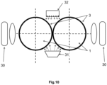
- each drum may be provided with its own plasma source (30), for example, next to the drum ( Fig. 10 ).
- At least one evaporator or magneton (31) containing the first common material is positioned at the bottom between the drums as described above, while at least one magnetron containing a target from the second common material (32) may be positioned at the top between the drums as described above .
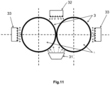
- each drum may additionally be provided with their own magnetron containing a target from the required material (33), which is positioned, for example, next to the drum ( Fig. 11 ).
- the set of technological devices may include similar technological devices with identical or different materials, or different technological devices with identical or different materials.
- the above-described deposition schemes are provided as an example, and do not limit the field of the patent or its application: the specified examples can be used to create other schemes realizing similar principles and ideas.
- the proposed invention allows for the use of different technological devices and combinations thereof.
- such devices as evaporators, electron beam evaporators (EBE), magnetrons, ionic sources and any other known technological devices can be used as technological devices for depositing materials.
- plasma sources, ionic sources, lamps, lasers and any other known plasma-generating devices can be used as technological devices for surface treatment.
- high uniformity of coating and high material collection coefficient can be provided by using the proposed design of the processing line.
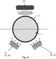
- Figure 12 shows a processing line with details on the relative orientation of individual technological devices such as equipment for depositioning of surface layering material as e.g. a magnetron or an evaporator for depositioning of metals, alloys, silicon, polymers or different materials with respect to the rotating drum that passes by those individual technological devices.
- equipment for depositioning of surface layering material e.g. a magnetron or an evaporator for depositioning of metals, alloys, silicon, polymers or different materials with respect to the rotating drum that passes by those individual technological devices.
- the moving direction of the drum on the carriage defines a canal which is surrounded e.g. by the processing chamber of the processing line.
- a gas separation installation might be provided which hinders material from the depositioning technological devices to enter a zone in which further processing of the depositioned material on the surface takes place.
- the processing zone can comprise e.g. a high-density plasma source which for example contains oxygen ions for oxidation of the layer material on that drum surface or any other above mentioned further processing installation.
- That gas separation installation might divide the canal defined by the moving direction of the drum into at least 2 longitudinal compartments. Such compartments might be provided in the top half and the bottom half of the processing chamber and might extend or a portion or the whole length of the processing chamber. With an according installation of multiple gas separation installations, more compartments are possible to be provided.
- At least one technological device for depositioning of layering material is provided.
- two of these sources are provided with in one compartment.
- the two technological devices e.g. embodied as magnetrons, may provide similar identical or different depositioning materials.
- the 1 st source provides for 1 st layer on that drum surface and the 2 nd source provides for 2 nd layer on the drum before the further processing in the 2 nd compartment via the technological devices for further processing, e.g. in the form of a high density plasma, is provid-ed/conducted.
- Such setup might also be provided with a multitude of depositioning material sources and further processing installations whereby each technological device might be provided in a separate compartment divided by the individual gas separation installations.
- the separation of technological devices might especially be useful in between the individual depositioning material sources, whereby further processing of the depositioned layer by more than one technological device might also be performed within a single together compartment.
Landscapes
- Chemical & Material Sciences (AREA)
- Chemical Kinetics & Catalysis (AREA)
- Engineering & Computer Science (AREA)
- Materials Engineering (AREA)
- Mechanical Engineering (AREA)
- Metallurgy (AREA)
- Organic Chemistry (AREA)
- General Chemical & Material Sciences (AREA)
- Physical Vapour Deposition (AREA)
Applications Claiming Priority (2)
| Application Number | Priority Date | Filing Date | Title |
|---|---|---|---|
| EP19160257 | 2019-03-01 | ||
| PCT/EP2020/055441 WO2020178238A1 (en) | 2019-03-01 | 2020-03-02 | Processing line for depositing thin-film coatings |
Publications (3)
| Publication Number | Publication Date |
|---|---|
| EP3931366A1 EP3931366A1 (en) | 2022-01-05 |
| EP3931366C0 EP3931366C0 (en) | 2024-07-31 |
| EP3931366B1 true EP3931366B1 (en) | 2024-07-31 |
Family
ID=65657362
Family Applications (1)
| Application Number | Title | Priority Date | Filing Date |
|---|---|---|---|
| EP20706535.0A Active EP3931366B1 (en) | 2019-03-01 | 2020-03-02 | Processing line for depositing thin-film coatings |
Country Status (4)
| Country | Link |
|---|---|
| US (1) | US20220145450A1 (pl) |
| EP (1) | EP3931366B1 (pl) |
| PL (1) | PL3931366T3 (pl) |
| WO (1) | WO2020178238A1 (pl) |
Families Citing this family (2)
| Publication number | Priority date | Publication date | Assignee | Title |
|---|---|---|---|---|
| US20240409350A1 (en) * | 2021-10-26 | 2024-12-12 | Frank SCHNAPPENBERGER | Vacuum processing system, apparatus and method for transporting a thin film substrate |
| CN115595545B (zh) * | 2022-09-27 | 2024-05-17 | 成都晨发泰达航空科技股份有限公司 | 一种eb-pvd涂层用的定位工装、加工设备及加工方法 |
Family Cites Families (7)
| Publication number | Priority date | Publication date | Assignee | Title |
|---|---|---|---|---|
| US4851095A (en) | 1988-02-08 | 1989-07-25 | Optical Coating Laboratory, Inc. | Magnetron sputtering apparatus and process |
| US6336999B1 (en) * | 2000-10-11 | 2002-01-08 | Centre Luxembourgeois De Recherches Pour Le Verre Et Al Ceramique S.A. (C.R.V.C.) | Apparatus for sputter-coating glass and corresponding method |
| JP2003119562A (ja) | 2001-08-14 | 2003-04-23 | Samsung Corning Co Ltd | インラインスパッタリング装置及びスパッタリング方法 |
| RU78785U1 (ru) | 2008-06-02 | 2008-12-10 | ООО НПО "КвинтТех" | Автоматизированная установка для формирования тонкопленочных покрытий наноразмерной толщины методом молекулярного наслаивания |
| RU2507308C1 (ru) | 2012-07-19 | 2014-02-20 | Айрат Хамитович Хисамов | Способ нанесения тонкопленочных покрытий и технологическая линия для его осуществления |
| PT3095890T (pt) * | 2014-01-14 | 2018-12-05 | The Batteries Spolka Z Ograniczona Odpowiedzialnoscia | Processo para a aplicação de revestimentos em película fina e linha de produção para a execução do processo |
| EA034967B1 (ru) * | 2018-05-04 | 2020-04-13 | Общество С Ограниченной Ответственностью "Изовак Технологии" | Технологическая линия для формирования тонкопленочных покрытий в вакууме (варианты) |
-
2020
- 2020-03-02 PL PL20706535.0T patent/PL3931366T3/pl unknown
- 2020-03-02 US US17/435,397 patent/US20220145450A1/en not_active Abandoned
- 2020-03-02 WO PCT/EP2020/055441 patent/WO2020178238A1/en not_active Ceased
- 2020-03-02 EP EP20706535.0A patent/EP3931366B1/en active Active
Also Published As
| Publication number | Publication date |
|---|---|
| EP3931366C0 (en) | 2024-07-31 |
| EP3931366A1 (en) | 2022-01-05 |
| PL3931366T3 (pl) | 2024-12-16 |
| US20220145450A1 (en) | 2022-05-12 |
| WO2020178238A1 (en) | 2020-09-10 |
Similar Documents
| Publication | Publication Date | Title |
|---|---|---|
| CN107923037B (zh) | 真空处理设备和用于真空处理基底的方法 | |
| JP3700793B2 (ja) | 真空処理装置、真空処理装置の中で基板を処理する方法、及び、真空処理装置用のロック | |
| JP2019049059A (ja) | プラズマを使った前処理装置を有した蒸着装置 | |
| JP2017513221A (ja) | 基板処理のためのシステム、基板処理のためのシステム用の真空回転モジュール、及び基板処理システムを操作する方法 | |
| US8070926B2 (en) | Multi-chamber workpiece processing | |
| US10385446B2 (en) | Thin film coating method and the manufacturing line for its implementation | |
| KR20190002834U (ko) | 진공에서의 박막 코팅 증착용 인-라인 코터 | |
| US20220145450A1 (en) | Processing line for depositing thin-film coatings | |
| RU2507308C1 (ru) | Способ нанесения тонкопленочных покрытий и технологическая линия для его осуществления | |
| US20250011919A1 (en) | Processing line for depositing thin-film coatings | |
| JP6768087B2 (ja) | フレキシブル基板を被覆するための堆積装置、フレキシブル基板を被覆する方法、及び被覆を有するフレキシブル基板 | |
| KR102899543B1 (ko) | 피처리 작업편을 고정하기 위한 이동가능 작업편 캐리어 디바이스 | |
| EP0537012A1 (en) | Sputtering processes and apparatus | |
| KR20210016036A (ko) | 성막 방법 | |
| US11174548B2 (en) | Thin film coating method and the manufacturing line for its implementation | |
| KR20100065624A (ko) | 기판 양면 증착을 위한 롤-투-룰 스퍼터 시스템 | |
| EP2868768B1 (en) | Shutter system | |
| EP1126045A2 (en) | Apparatus for coating substrates | |
| JP6451030B2 (ja) | 成膜装置 | |
| HK1228965B (zh) | 薄膜涂覆方法及实施该方法的生产线 | |
| HK1228965A1 (en) | Thin film coating method and the manufacturing line for its implementation | |
| JPH05230648A (ja) | スパッタリング装置 | |
| CN113718215A (zh) | 磁控溅射设备 | |
| WO2011121665A1 (ja) | 電子デバイスの製造装置及びこれを用いた電子デバイスの製造方法 | |
| JPH03115569A (ja) | 金属膜生成装置 |
Legal Events
| Date | Code | Title | Description |
|---|---|---|---|
| STAA | Information on the status of an ep patent application or granted ep patent |
Free format text: STATUS: UNKNOWN |
|
| STAA | Information on the status of an ep patent application or granted ep patent |
Free format text: STATUS: THE INTERNATIONAL PUBLICATION HAS BEEN MADE |
|
| PUAI | Public reference made under article 153(3) epc to a published international application that has entered the european phase |
Free format text: ORIGINAL CODE: 0009012 |
|
| STAA | Information on the status of an ep patent application or granted ep patent |
Free format text: STATUS: REQUEST FOR EXAMINATION WAS MADE |
|
| 17P | Request for examination filed |
Effective date: 20211001 |
|
| AK | Designated contracting states |
Kind code of ref document: A1 Designated state(s): AL AT BE BG CH CY CZ DE DK EE ES FI FR GB GR HR HU IE IS IT LI LT LU LV MC MK MT NL NO PL PT RO RS SE SI SK SM TR |
|
| DAV | Request for validation of the european patent (deleted) | ||
| DAX | Request for extension of the european patent (deleted) | ||
| STAA | Information on the status of an ep patent application or granted ep patent |
Free format text: STATUS: EXAMINATION IS IN PROGRESS |
|
| 17Q | First examination report despatched |
Effective date: 20220627 |
|
| GRAP | Despatch of communication of intention to grant a patent |
Free format text: ORIGINAL CODE: EPIDOSNIGR1 |
|
| STAA | Information on the status of an ep patent application or granted ep patent |
Free format text: STATUS: GRANT OF PATENT IS INTENDED |
|
| INTG | Intention to grant announced |
Effective date: 20240228 |
|
| GRAS | Grant fee paid |
Free format text: ORIGINAL CODE: EPIDOSNIGR3 |
|
| GRAA | (expected) grant |
Free format text: ORIGINAL CODE: 0009210 |
|
| STAA | Information on the status of an ep patent application or granted ep patent |
Free format text: STATUS: THE PATENT HAS BEEN GRANTED |
|
| AK | Designated contracting states |
Kind code of ref document: B1 Designated state(s): AL AT BE BG CH CY CZ DE DK EE ES FI FR GB GR HR HU IE IS IT LI LT LU LV MC MK MT NL NO PL PT RO RS SE SI SK SM TR |
|
| REG | Reference to a national code |
Ref country code: CH Ref legal event code: EP Ref country code: GB Ref legal event code: FG4D |
|
| REG | Reference to a national code |
Ref country code: DE Ref legal event code: R096 Ref document number: 602020034822 Country of ref document: DE |
|
| REG | Reference to a national code |
Ref country code: IE Ref legal event code: FG4D |
|
| U01 | Request for unitary effect filed |
Effective date: 20240902 |
|
| U07 | Unitary effect registered |
Designated state(s): AT BE BG DE DK EE FI FR IT LT LU LV MT NL PT RO SE SI Effective date: 20240912 |
|
| PG25 | Lapsed in a contracting state [announced via postgrant information from national office to epo] |
Ref country code: NO Free format text: LAPSE BECAUSE OF FAILURE TO SUBMIT A TRANSLATION OF THE DESCRIPTION OR TO PAY THE FEE WITHIN THE PRESCRIBED TIME-LIMIT Effective date: 20241031 |
|
| PG25 | Lapsed in a contracting state [announced via postgrant information from national office to epo] |
Ref country code: GR Free format text: LAPSE BECAUSE OF FAILURE TO SUBMIT A TRANSLATION OF THE DESCRIPTION OR TO PAY THE FEE WITHIN THE PRESCRIBED TIME-LIMIT Effective date: 20241101 |
|
| PG25 | Lapsed in a contracting state [announced via postgrant information from national office to epo] |
Ref country code: IS Free format text: LAPSE BECAUSE OF FAILURE TO SUBMIT A TRANSLATION OF THE DESCRIPTION OR TO PAY THE FEE WITHIN THE PRESCRIBED TIME-LIMIT Effective date: 20241130 |
|
| PG25 | Lapsed in a contracting state [announced via postgrant information from national office to epo] |
Ref country code: HR Free format text: LAPSE BECAUSE OF FAILURE TO SUBMIT A TRANSLATION OF THE DESCRIPTION OR TO PAY THE FEE WITHIN THE PRESCRIBED TIME-LIMIT Effective date: 20240731 |
|
| PG25 | Lapsed in a contracting state [announced via postgrant information from national office to epo] |
Ref country code: ES Free format text: LAPSE BECAUSE OF FAILURE TO SUBMIT A TRANSLATION OF THE DESCRIPTION OR TO PAY THE FEE WITHIN THE PRESCRIBED TIME-LIMIT Effective date: 20240731 Ref country code: RS Free format text: LAPSE BECAUSE OF FAILURE TO SUBMIT A TRANSLATION OF THE DESCRIPTION OR TO PAY THE FEE WITHIN THE PRESCRIBED TIME-LIMIT Effective date: 20241031 |
|
| PG25 | Lapsed in a contracting state [announced via postgrant information from national office to epo] |
Ref country code: RS Free format text: LAPSE BECAUSE OF FAILURE TO SUBMIT A TRANSLATION OF THE DESCRIPTION OR TO PAY THE FEE WITHIN THE PRESCRIBED TIME-LIMIT Effective date: 20241031 Ref country code: NO Free format text: LAPSE BECAUSE OF FAILURE TO SUBMIT A TRANSLATION OF THE DESCRIPTION OR TO PAY THE FEE WITHIN THE PRESCRIBED TIME-LIMIT Effective date: 20241031 Ref country code: IS Free format text: LAPSE BECAUSE OF FAILURE TO SUBMIT A TRANSLATION OF THE DESCRIPTION OR TO PAY THE FEE WITHIN THE PRESCRIBED TIME-LIMIT Effective date: 20241130 Ref country code: HR Free format text: LAPSE BECAUSE OF FAILURE TO SUBMIT A TRANSLATION OF THE DESCRIPTION OR TO PAY THE FEE WITHIN THE PRESCRIBED TIME-LIMIT Effective date: 20240731 Ref country code: GR Free format text: LAPSE BECAUSE OF FAILURE TO SUBMIT A TRANSLATION OF THE DESCRIPTION OR TO PAY THE FEE WITHIN THE PRESCRIBED TIME-LIMIT Effective date: 20241101 Ref country code: ES Free format text: LAPSE BECAUSE OF FAILURE TO SUBMIT A TRANSLATION OF THE DESCRIPTION OR TO PAY THE FEE WITHIN THE PRESCRIBED TIME-LIMIT Effective date: 20240731 |
|
| PG25 | Lapsed in a contracting state [announced via postgrant information from national office to epo] |
Ref country code: SM Free format text: LAPSE BECAUSE OF FAILURE TO SUBMIT A TRANSLATION OF THE DESCRIPTION OR TO PAY THE FEE WITHIN THE PRESCRIBED TIME-LIMIT Effective date: 20240731 |
|
| PG25 | Lapsed in a contracting state [announced via postgrant information from national office to epo] |
Ref country code: CZ Free format text: LAPSE BECAUSE OF FAILURE TO SUBMIT A TRANSLATION OF THE DESCRIPTION OR TO PAY THE FEE WITHIN THE PRESCRIBED TIME-LIMIT Effective date: 20240731 |
|
| PG25 | Lapsed in a contracting state [announced via postgrant information from national office to epo] |
Ref country code: SK Free format text: LAPSE BECAUSE OF FAILURE TO SUBMIT A TRANSLATION OF THE DESCRIPTION OR TO PAY THE FEE WITHIN THE PRESCRIBED TIME-LIMIT Effective date: 20240731 |
|
| U20 | Renewal fee for the european patent with unitary effect paid |
Year of fee payment: 6 Effective date: 20250328 |
|
| PLBE | No opposition filed within time limit |
Free format text: ORIGINAL CODE: 0009261 |
|
| STAA | Information on the status of an ep patent application or granted ep patent |
Free format text: STATUS: NO OPPOSITION FILED WITHIN TIME LIMIT |
|
| 26N | No opposition filed |
Effective date: 20250501 |
|
| PG25 | Lapsed in a contracting state [announced via postgrant information from national office to epo] |
Ref country code: MC Free format text: LAPSE BECAUSE OF FAILURE TO SUBMIT A TRANSLATION OF THE DESCRIPTION OR TO PAY THE FEE WITHIN THE PRESCRIBED TIME-LIMIT Effective date: 20240731 |
|
| REG | Reference to a national code |
Ref country code: CH Ref legal event code: H13 Free format text: ST27 STATUS EVENT CODE: U-0-0-H10-H13 (AS PROVIDED BY THE NATIONAL OFFICE) Effective date: 20251023 |
|
| GBPC | Gb: european patent ceased through non-payment of renewal fee |
Effective date: 20250302 |
|
| PG25 | Lapsed in a contracting state [announced via postgrant information from national office to epo] |
Ref country code: GB Free format text: LAPSE BECAUSE OF NON-PAYMENT OF DUE FEES Effective date: 20250302 |
|
| PG25 | Lapsed in a contracting state [announced via postgrant information from national office to epo] |
Ref country code: CH Free format text: LAPSE BECAUSE OF NON-PAYMENT OF DUE FEES Effective date: 20250331 |
|
| PG25 | Lapsed in a contracting state [announced via postgrant information from national office to epo] |
Ref country code: IE Free format text: LAPSE BECAUSE OF NON-PAYMENT OF DUE FEES Effective date: 20250302 |
|
| PGFP | Annual fee paid to national office [announced via postgrant information from national office to epo] |
Ref country code: PL Payment date: 20260219 Year of fee payment: 7 |
|
| U20 | Renewal fee for the european patent with unitary effect paid |
Year of fee payment: 7 Effective date: 20260319 |