EP3930030A1 - Battery cell assembly, method of manufacturing same, and battery module including battery cell assembly - Google Patents
Battery cell assembly, method of manufacturing same, and battery module including battery cell assembly Download PDFInfo
- Publication number
- EP3930030A1 EP3930030A1 EP20806505.2A EP20806505A EP3930030A1 EP 3930030 A1 EP3930030 A1 EP 3930030A1 EP 20806505 A EP20806505 A EP 20806505A EP 3930030 A1 EP3930030 A1 EP 3930030A1
- Authority
- EP
- European Patent Office
- Prior art keywords
- battery cell
- component type
- type liquid
- battery
- liquid material
- Prior art date
- Legal status (The legal status is an assumption and is not a legal conclusion. Google has not performed a legal analysis and makes no representation as to the accuracy of the status listed.)
- Pending
Links
Images


Classifications
-
- H—ELECTRICITY
- H01—ELECTRIC ELEMENTS
- H01M—PROCESSES OR MEANS, e.g. BATTERIES, FOR THE DIRECT CONVERSION OF CHEMICAL ENERGY INTO ELECTRICAL ENERGY
- H01M50/00—Constructional details or processes of manufacture of the non-active parts of electrochemical cells other than fuel cells, e.g. hybrid cells
- H01M50/20—Mountings; Secondary casings or frames; Racks, modules or packs; Suspension devices; Shock absorbers; Transport or carrying devices; Holders
-
- H—ELECTRICITY
- H01—ELECTRIC ELEMENTS
- H01M—PROCESSES OR MEANS, e.g. BATTERIES, FOR THE DIRECT CONVERSION OF CHEMICAL ENERGY INTO ELECTRICAL ENERGY
- H01M50/00—Constructional details or processes of manufacture of the non-active parts of electrochemical cells other than fuel cells, e.g. hybrid cells
- H01M50/20—Mountings; Secondary casings or frames; Racks, modules or packs; Suspension devices; Shock absorbers; Transport or carrying devices; Holders
- H01M50/204—Racks, modules or packs for multiple batteries or multiple cells
- H01M50/207—Racks, modules or packs for multiple batteries or multiple cells characterised by their shape
- H01M50/209—Racks, modules or packs for multiple batteries or multiple cells characterised by their shape adapted for prismatic or rectangular cells
-
- H—ELECTRICITY
- H01—ELECTRIC ELEMENTS
- H01M—PROCESSES OR MEANS, e.g. BATTERIES, FOR THE DIRECT CONVERSION OF CHEMICAL ENERGY INTO ELECTRICAL ENERGY
- H01M50/00—Constructional details or processes of manufacture of the non-active parts of electrochemical cells other than fuel cells, e.g. hybrid cells
- H01M50/20—Mountings; Secondary casings or frames; Racks, modules or packs; Suspension devices; Shock absorbers; Transport or carrying devices; Holders
- H01M50/204—Racks, modules or packs for multiple batteries or multiple cells
- H01M50/207—Racks, modules or packs for multiple batteries or multiple cells characterised by their shape
- H01M50/211—Racks, modules or packs for multiple batteries or multiple cells characterised by their shape adapted for pouch cells
-
- H—ELECTRICITY
- H01—ELECTRIC ELEMENTS
- H01M—PROCESSES OR MEANS, e.g. BATTERIES, FOR THE DIRECT CONVERSION OF CHEMICAL ENERGY INTO ELECTRICAL ENERGY
- H01M50/00—Constructional details or processes of manufacture of the non-active parts of electrochemical cells other than fuel cells, e.g. hybrid cells
- H01M50/20—Mountings; Secondary casings or frames; Racks, modules or packs; Suspension devices; Shock absorbers; Transport or carrying devices; Holders
- H01M50/233—Mountings; Secondary casings or frames; Racks, modules or packs; Suspension devices; Shock absorbers; Transport or carrying devices; Holders characterised by physical properties of casings or racks, e.g. dimensions
- H01M50/24—Mountings; Secondary casings or frames; Racks, modules or packs; Suspension devices; Shock absorbers; Transport or carrying devices; Holders characterised by physical properties of casings or racks, e.g. dimensions adapted for protecting batteries from their environment, e.g. from corrosion
-
- H—ELECTRICITY
- H01—ELECTRIC ELEMENTS
- H01M—PROCESSES OR MEANS, e.g. BATTERIES, FOR THE DIRECT CONVERSION OF CHEMICAL ENERGY INTO ELECTRICAL ENERGY
- H01M50/00—Constructional details or processes of manufacture of the non-active parts of electrochemical cells other than fuel cells, e.g. hybrid cells
- H01M50/60—Arrangements or processes for filling or topping-up with liquids; Arrangements or processes for draining liquids from casings
-
- C—CHEMISTRY; METALLURGY
- C09—DYES; PAINTS; POLISHES; NATURAL RESINS; ADHESIVES; COMPOSITIONS NOT OTHERWISE PROVIDED FOR; APPLICATIONS OF MATERIALS NOT OTHERWISE PROVIDED FOR
- C09J—ADHESIVES; NON-MECHANICAL ASPECTS OF ADHESIVE PROCESSES IN GENERAL; ADHESIVE PROCESSES NOT PROVIDED FOR ELSEWHERE; USE OF MATERIALS AS ADHESIVES
- C09J2203/00—Applications of adhesives in processes or use of adhesives in the form of films or foils
- C09J2203/33—Applications of adhesives in processes or use of adhesives in the form of films or foils for batteries or fuel cells
-
- Y—GENERAL TAGGING OF NEW TECHNOLOGICAL DEVELOPMENTS; GENERAL TAGGING OF CROSS-SECTIONAL TECHNOLOGIES SPANNING OVER SEVERAL SECTIONS OF THE IPC; TECHNICAL SUBJECTS COVERED BY FORMER USPC CROSS-REFERENCE ART COLLECTIONS [XRACs] AND DIGESTS
- Y02—TECHNOLOGIES OR APPLICATIONS FOR MITIGATION OR ADAPTATION AGAINST CLIMATE CHANGE
- Y02E—REDUCTION OF GREENHOUSE GAS [GHG] EMISSIONS, RELATED TO ENERGY GENERATION, TRANSMISSION OR DISTRIBUTION
- Y02E60/00—Enabling technologies; Technologies with a potential or indirect contribution to GHG emissions mitigation
- Y02E60/10—Energy storage using batteries
-
- Y—GENERAL TAGGING OF NEW TECHNOLOGICAL DEVELOPMENTS; GENERAL TAGGING OF CROSS-SECTIONAL TECHNOLOGIES SPANNING OVER SEVERAL SECTIONS OF THE IPC; TECHNICAL SUBJECTS COVERED BY FORMER USPC CROSS-REFERENCE ART COLLECTIONS [XRACs] AND DIGESTS
- Y02—TECHNOLOGIES OR APPLICATIONS FOR MITIGATION OR ADAPTATION AGAINST CLIMATE CHANGE
- Y02P—CLIMATE CHANGE MITIGATION TECHNOLOGIES IN THE PRODUCTION OR PROCESSING OF GOODS
- Y02P70/00—Climate change mitigation technologies in the production process for final industrial or consumer products
- Y02P70/50—Manufacturing or production processes characterised by the final manufactured product
Definitions
- the present disclosure relates to a battery cell assembly and a method of manufacturing the same, and more particularly, to a battery cell assembly capable of reducing defects in the process and improving profitability, and a method of manufacturing the same.
- Secondary batteries which are easily applied to various product groups and has electrical characteristics such as high energy density, are universally applied not only for a portable device but also for an electric vehicle (EV) or a hybrid electric vehicle (HEV), an energy storage system or the like, which is driven by an electric driving source.
- EV electric vehicle
- HEV hybrid electric vehicle
- Such secondary battery is attracting attention as a new environment-friendly energy source for improving energy efficiency since it gives a primary advantage of remarkably reducing the use of fossil fuels and also does not generate by-products from the use of energy at all.
- Small-sized mobile devices use one or several battery cells for each device, whereas middle- or large-sized devices such as vehicles require high power and large capacity. Therefore, a middle- or large-sized battery module having a plurality of battery cells electrically connected to one another is used.
- the middle- or large-sized battery module is manufactured so as to have as small a size and weight as possible. Consequently, a prismatic battery or a pouch-shaped battery, which can be stacked with high integration and has a small weight to capacity ratio, is usually used as a battery cell of the middle- or large-sized battery module. Especially, much interest is currently focused on the pouch-shaped battery, which uses an aluminum laminate sheet as a battery cell.
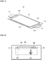
- FIG. 1 is a perspective view showing a conventional pouch-shaped battery.
- the secondary battery 10 has a structure in which two electrode leads 11 and 12 are opposed to each other and protrude from one end 14a and the other end 14b of the battery body 13, respectively, and is manufactured by connecting them with both ends 14a and 14b of the battery case 14 and both side surfaces 14c in a state where the electrode assembly (not shown) is housed in the battery case 14.
- the battery case is generally composed of a laminated structure of a resin layer/metal thin film layer/resin layer.
- the surface of the battery case is composed of an O (oriented)-nylon layer
- an adhesive member for example, a cohesive type adhesive agent such as a double-sided tape or a chemical adhesive agent coupled by a chemical reaction during coupling, is attached to the surface of the battery case, and the battery cells are stacked one on another to form a medium- to large-sized battery module.
- the double-sided tape requires continuous management during the process because defects are occurred, such as the problem that the tape is not transferred or is stretched, and the unit price is high which results in a reduction in profitability.
- the present disclosure has been made to solve the above-mentioned problems, and an object of the present disclosure to provide a battery cell assembly that can reduce defects in the process and improve profitability by using a one-component type liquid material capable of replacing a double-sided tape, and a method of manufacturing the same.
- a battery cell assembly comprises a plurality of battery cells that are stacked in one direction, battery cells adjacent to each other among the plurality of battery cells being coupled by a one-component type material, wherein the one-component type material is an alcohol-based material or a water-based material.
- the one-component type material may include at least two pattern portions parallel to each other on one surface of the battery cell.
- the one-component type material may be physically separated or may be separated using a chemical material.
- a battery module according to another embodiment of the present disclosure may comprise the above-mentioned battery cell assembly.
- a method of manufacturing the battery cell assembly according to yet another embodiment of the present disclosure comprises a step of coupling battery cells adjacent to each other among the plurality of battery cells that are stacked in one direction, using a one-component type liquid material, wherein the one-component type liquid material is coated onto the battery cell by a spray-coating method.
- the one-component type liquid material is a one-component type liquid adhesive agent or a one-component type liquid cohesive agent
- the one-component type liquid adhesive agent is an alcohol-based adhesive agent
- the one-component type liquid cohesive agent may be a water-based cohesive agent.
- the step of connecting the battery cells using the one-component type liquid material may be carried out in such a manner that a spray valve sprays the one-component type liquid material from the lower part of the battery cell toward the battery cell, thereby coating the one-component type liquid material onto the lower surface of the battery cell.
- the step of coupling the battery cells using the one-component type liquid material may further include a step of automatically transferring the battery cells to a spray station by a conveyor; and a step of spraying the one-component type material on the lower surface of the battery cell while moving a spray valve in a state where the battery cell is fixed.
- the method of manufacturing the battery cell assembly may further include a step of picking up an upper surface of the battery cell, so that the plurality of battery cells are stacked.
- the method may further include a step of automatically transferring the battery cell coated by the one-component type liquid material to a drying station by a conveyor, and then drying the one-component type liquid material.
- the drying condition may be set such that a surface temperature of the battery cell is lower than a driving temperature of the battery cell.
- the step of drying the one-component type liquid material may use a hot air or an ultraviolet irradiation method.
- the space utilization in the process can be increased and the interference with other mechanical devices can be eliminated.
- the step of mixing a stock solution and a curing agent required for the two-component type liquid adhesive agent can be eliminated to reduce the cost.
- liquid material By using the liquid material, it is possible to realize adhesive shapes having various patterns according to the width of the battery cell.
- planar when referred to as “planar”, it means when a target portion is viewed from the top, and when referred to as “cross-sectional”, it means when a target portion is viewed from the side of a cross section cut vertically.
- FIGS. 2 to 6 are views showing a method of manufacturing a battery cell assembly according to an embodiment of the present disclosure.
- the battery cell 100 has a structure in which two electrode leads 110 and 120 having different polarities are opposed to each other and protrude from one end and the other end of the battery body, respectively, and is manufactured by adhering both ends and of the battery case and both side surfaces connecting them in a state when the electrode assembly is housed in the battery case.
- the battery case is generally composed of a laminated structure of a resin layer/metal thin film layer/resin layer.
- the method for manufacturing a battery cell assembly may include a step of automatically transferring a battery cell 100 to a spray station 500 by a conveyor.
- the conveyor is a mechanical device that automatically and continuously conveys between a certain distance, and for example, belt conveyors or roller conveyors may be used.
- the conveyor is a generally well-known mechanical device, so its illustration will be omitted.
- the battery cell 100 that has been transferred to the spray station 500 can move according to the input coordinate value preset by a spray valve 310 in a state where its position is fixed.
- the spray valve 310 sprays an adhesive agent 300 from the lower part of the battery cell 100 toward the battery cell 100, so that the liquid material 300 is coated onto the lower surface 100L of the battery cell.
- a general spraying process is a method in which the material sprayed by the spray is sprayed toward an object located at the lower part from the upper part of the object to be reached, but in the present embodiment, since the spray direction is reversed compared to the conventional one, there is an advantage that the process utilization in the process is improved and interference with other devices is eliminated.
- the spray valve 310 moves from the lower surface 100L of the battery cell adjacent to the positive electrode lead 120 toward the lower surface 100L of the battery cell of the negative electrode lead 110, it can spray the liquid material 300.
- the spray valve 310 may use a circular pattern spray or a fan pattern spray, depending on the width of the battery cell 100.
- the liquid material 300 uses a one-component type liquid material, and the one-component type liquid material may be a one-component type liquid adhesive agent or a one-component type liquid cohesive agent.
- the one-component type liquid adhesive agent may be an alcohol-based adhesive agent
- the one-component type liquid cohesive agent may be a water-based adhesive agent.
- the alcohol-based adhesive agent has quick initial curing and can detach neighboring battery cells using chemical materials. Even after detachment, the adhesive properties can be maintained.
- the water-based cohesive agent is an environmentally friendly material, and it can detach adjacent battery cells by physical force, and the cohesive properties can be maintained even after detachment.
- the method may further include a step of automatically transferring the battery cell 100 coated by the liquid substance 300 to the drying station 600 by a conveyor and then drying the liquid material 300.
- hot air 610 from a hot air dryer was used to dry the liquid material 300, but an ultraviolet irradiation method can also be used.
- the drying condition is preferably set such that the surface temperature of the battery cell is lower than the driving temperature of the battery cell.
- the one-component type liquid material 300 is an alcohol-based adhesive agent
- a separate curing process is unnecessary, and thus, the above-described drying process may be omitted.
- the method of manufacturing a battery cell assembly according to the present embodiment may further include a step of picking up the upper surface of the battery cell 100, so that the plurality of battery cells are stacked.
- the upper surface of the battery cell 100 may be a surface corresponding to the lower surface 100L of the battery cell on which the liquid material 300 is formed, and may be a surface on which the liquid material 300 is not formed.
- the battery cell assembly according to the present embodiment includes a first battery cell 100a, a second battery cell 100b which is adhered on the first battery cell 100a by the one-component type liquid material 300, and a third battery cell 100c which is stacked on the 100b. In this way, a plurality of battery cells are stacked to form a battery cell assembly, and electrode leads of the plurality of battery cells may be electrically connected.
- a pickup robot 400 may be used to pick up the upper surface of the battery cell 100.
- the pickup robot 400 may perform a lamination process so that a preset coordinate value is input to stably pick up the upper surface of the battery cell 100 and adhere to adjacent battery cells.
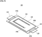
- FIG. 7 is a perspective view of a battery cell assembly according to another embodiment of the present invention.
- the battery cell 100 has a structure in which two electrode leads 110 and 120 are opposite to each other and protrude from one end 140a and the other end 140b of the battery body 13, respectively, and can be manufactured by adhering both ends 140a and 140b of the battery case 140 and both side surfaces 140c connecting them in a state when the electrode assembly (not shown) is housed in the battery case 140. Thereafter, the liquid material 300 may be formed on the lower surface of the battery cell 100 according to the method described in FIGS. 2 to 6 .
- the figure shown in FIG. 7 may be a state in which the one-component type liquid material 300 is formed on the lower surface of the battery cell 100 and then turned upside down.
- one liquid material 300 pattern extending long in one direction of the battery cell 100 may be formed, but as a modified embodiment, the shapes of the liquid material 300 having various patterns as described below can also be realized.
- a pattern of a " ⁇ " shaped liquid material 300 may be formed by changing the coating shape according to the spraying method.
- the liquid material 300 according to the present embodiment may be formed of a one-component type liquid material, and the one-component type liquid material may form at least two parallel pattern portions on one surface of the battery cell 100.
- the “ ⁇ " shape it is possible to realize the shape of the liquid material 300 having various patterns according to the width of the battery cell.
- the liquid material 300 becomes an adhesive layer between adjacent battery cells 100 after drying or curing.
- the battery cell assembly according to various embodiments described above may be combined with a bus bar, a bus bar frame, a case, and the like to form a battery module.
Landscapes
- Chemical & Material Sciences (AREA)
- Chemical Kinetics & Catalysis (AREA)
- Electrochemistry (AREA)
- General Chemical & Material Sciences (AREA)
- Battery Mounting, Suspending (AREA)
- Secondary Cells (AREA)
- Primary Cells (AREA)
Abstract
Description
- This application claims the benefit of
Korean Patent Application No. 10-2019-0056450 filed on May 14, 2019 - The present disclosure relates to a battery cell assembly and a method of manufacturing the same, and more particularly, to a battery cell assembly capable of reducing defects in the process and improving profitability, and a method of manufacturing the same.
- Secondary batteries, which are easily applied to various product groups and has electrical characteristics such as high energy density, are universally applied not only for a portable device but also for an electric vehicle (EV) or a hybrid electric vehicle (HEV), an energy storage system or the like, which is driven by an electric driving source. Such secondary battery is attracting attention as a new environment-friendly energy source for improving energy efficiency since it gives a primary advantage of remarkably reducing the use of fossil fuels and also does not generate by-products from the use of energy at all. Small-sized mobile devices use one or several battery cells for each device, whereas middle- or large-sized devices such as vehicles require high power and large capacity. Therefore, a middle- or large-sized battery module having a plurality of battery cells electrically connected to one another is used.
- Preferably, the middle- or large-sized battery module is manufactured so as to have as small a size and weight as possible. Consequently, a prismatic battery or a pouch-shaped battery, which can be stacked with high integration and has a small weight to capacity ratio, is usually used as a battery cell of the middle- or large-sized battery module. Especially, much interest is currently focused on the pouch-shaped battery, which uses an aluminum laminate sheet as a battery cell.
-
FIG. 1 is a perspective view showing a conventional pouch-shaped battery. Referring toFIG. 1 , thesecondary battery 10 has a structure in which two electrode leads 11 and 12 are opposed to each other and protrude from oneend 14a and theother end 14b of thebattery body 13, respectively, and is manufactured by connecting them with bothends battery case 14 and bothside surfaces 14c in a state where the electrode assembly (not shown) is housed in thebattery case 14. - The battery case is generally composed of a laminated structure of a resin layer/metal thin film layer/resin layer. For example, in the case where the surface of the battery case is composed of an O (oriented)-nylon layer, when a plurality of battery cells are stacked in order to form a middle- or large-sized battery module, they tend to slip easily due to an external impact. Therefore, in order to prevent this and maintain a stable laminated structure of the battery cells, an adhesive member, for example, a cohesive type adhesive agent such as a double-sided tape or a chemical adhesive agent coupled by a chemical reaction during coupling, is attached to the surface of the battery case, and the battery cells are stacked one on another to form a medium- to large-sized battery module.
- However, when this type of the adhesive member is used for a long period of time, the adhesive component is deteriorated and thus, the adhesive strength may be significantly reduced. In addition, the double-sided tape requires continuous management during the process because defects are occurred, such as the problem that the tape is not transferred or is stretched, and the unit price is high which results in a reduction in profitability.
- The present disclosure has been made to solve the above-mentioned problems, and an object of the present disclosure to provide a battery cell assembly that can reduce defects in the process and improve profitability by using a one-component type liquid material capable of replacing a double-sided tape, and a method of manufacturing the same.
- However, the problem to be solved by embodiments of the present disclosure is not limited to the above-described problems, and can be variously expanded within the scope of the technical idea included in the present disclosure.
- A battery cell assembly according to one embodiment of the present disclosure comprises a plurality of battery cells that are stacked in one direction, battery cells adjacent to each other among the plurality of battery cells being coupled by a one-component type material, wherein the one-component type material is an alcohol-based material or a water-based material.
- The one-component type material may include at least two pattern portions parallel to each other on one surface of the battery cell.
- The one-component type material may be physically separated or may be separated using a chemical material.
- A battery module according to another embodiment of the present disclosure may comprise the above-mentioned battery cell assembly.
- A method of manufacturing the battery cell assembly according to yet another embodiment of the present disclosure comprises a step of coupling battery cells adjacent to each other among the plurality of battery cells that are stacked in one direction, using a one-component type liquid material, wherein the one-component type liquid material is coated onto the battery cell by a spray-coating method.
- The one-component type liquid material is a one-component type liquid adhesive agent or a one-component type liquid cohesive agent, the one-component type liquid adhesive agent is an alcohol-based adhesive agent, and the one-component type liquid cohesive agent may be a water-based cohesive agent.
- The step of connecting the battery cells using the one-component type liquid material may be carried out in such a manner that a spray valve sprays the one-component type liquid material from the lower part of the battery cell toward the battery cell, thereby coating the one-component type liquid material onto the lower surface of the battery cell.
- The step of coupling the battery cells using the one-component type liquid material may further include a step of automatically transferring the battery cells to a spray station by a conveyor; and a step of spraying the one-component type material on the lower surface of the battery cell while moving a spray valve in a state where the battery cell is fixed.
- The method of manufacturing the battery cell assembly may further include a step of picking up an upper surface of the battery cell, so that the plurality of battery cells are stacked.
- When the one-component type liquid material is a water-based adhesive agent, the method may further include a step of automatically transferring the battery cell coated by the one-component type liquid material to a drying station by a conveyor, and then drying the one-component type liquid material.
- In the step of drying the one-component type liquid material, the drying condition may be set such that a surface temperature of the battery cell is lower than a driving temperature of the battery cell.
- The step of drying the one-component type liquid material may use a hot air or an ultraviolet irradiation method.
- According to the embodiments, by replacing the double-sided tape with a one-component type liquid material, defects caused by using a conventional double-sided tape can be reduced.
- Also, unlike the conventional one, by spraying a one-component type liquid material toward the lower surface of the battery cell, the space utilization in the process can be increased and the interference with other mechanical devices can be eliminated.
- Further, by using the one-component type liquid material, the step of mixing a stock solution and a curing agent required for the two-component type liquid adhesive agent can be eliminated to reduce the cost.
- In addition, by using the liquid material, it is possible to realize adhesive shapes having various patterns according to the width of the battery cell.
-
-
FIG. 1 is a perspective view showing a conventional pouch-shaped battery. -
FIGS. 2 to 6 are views showing a method of manufacturing a battery cell assembly according to an embodiment of the present disclosure. -
FIG. 7 is a perspective view showing a battery cell assembly according to another embodiment of the present disclosure. - Hereinafter, various embodiments of the present disclosure will be described in detail with reference to the accompanying drawings so that those skilled in the art can easily implement them. The present disclosure may be modified in various different ways, and is not limited to the embodiments set forth herein.
- Parts that are irrelevant to the description will be omitted to clearly describe the present disclosure, and like reference numerals designate like elements throughout the specification.
- Further, in the drawings, the size and thickness of each element are arbitrarily illustrated for convenience of description, and the present disclosure is not necessarily limited to those illustrated in the drawings. In the drawings, the thickness of layers, regions, etc. are exaggerated for clarity. In the drawings, for convenience of description, the thicknesses of some layers and regions are exaggerated.
- In addition, it will be understood that when an element such as a layer, film, region, or plate is referred to as being "on" or "above" another element, it can be directly on the other element or intervening elements may also be present. In contrast, when an element is referred to as being "directly on" another element, it means that other intervening elements are not present. Further, the word "on" or "above" means disposed on or below a reference portion, and does not necessarily mean being disposed on the upper end of the reference portion toward the opposite direction of gravity.
- Further, throughout the specification, when a part is referred to as "including" a certain component, it means that it can further include other components, without excluding the other components, unless otherwise stated.
- Further, throughout the specification, when referred to as "planar", it means when a target portion is viewed from the top, and when referred to as "cross-sectional", it means when a target portion is viewed from the side of a cross section cut vertically.
-
FIGS. 2 to 6 are views showing a method of manufacturing a battery cell assembly according to an embodiment of the present disclosure. - Referring to
FIG. 2 , thebattery cell 100 according to the present embodiment has a structure in which two electrode leads 110 and 120 having different polarities are opposed to each other and protrude from one end and the other end of the battery body, respectively, and is manufactured by adhering both ends and of the battery case and both side surfaces connecting them in a state when the electrode assembly is housed in the battery case. The battery case is generally composed of a laminated structure of a resin layer/metal thin film layer/resin layer. - The method for manufacturing a battery cell assembly according to the present embodiment may include a step of automatically transferring a
battery cell 100 to aspray station 500 by a conveyor. Here, the conveyor is a mechanical device that automatically and continuously conveys between a certain distance, and for example, belt conveyors or roller conveyors may be used. The conveyor is a generally well-known mechanical device, so its illustration will be omitted. - The
battery cell 100 that has been transferred to thespray station 500 can move according to the input coordinate value preset by aspray valve 310 in a state where its position is fixed. At this time, thespray valve 310 sprays anadhesive agent 300 from the lower part of thebattery cell 100 toward thebattery cell 100, so that theliquid material 300 is coated onto thelower surface 100L of the battery cell. A general spraying process is a method in which the material sprayed by the spray is sprayed toward an object located at the lower part from the upper part of the object to be reached, but in the present embodiment, since the spray direction is reversed compared to the conventional one, there is an advantage that the process utilization in the process is improved and interference with other devices is eliminated. - As an example, as shown in
FIGS. 2 and3 , while thespray valve 310 moves from thelower surface 100L of the battery cell adjacent to thepositive electrode lead 120 toward thelower surface 100L of the battery cell of thenegative electrode lead 110, it can spray theliquid material 300. Thespray valve 310 may use a circular pattern spray or a fan pattern spray, depending on the width of thebattery cell 100. - The
liquid material 300 according to the present embodiment uses a one-component type liquid material, and the one-component type liquid material may be a one-component type liquid adhesive agent or a one-component type liquid cohesive agent. At this time, the one-component type liquid adhesive agent may be an alcohol-based adhesive agent, and the one-component type liquid cohesive agent may be a water-based adhesive agent. The alcohol-based adhesive agent has quick initial curing and can detach neighboring battery cells using chemical materials. Even after detachment, the adhesive properties can be maintained. The water-based cohesive agent is an environmentally friendly material, and it can detach adjacent battery cells by physical force, and the cohesive properties can be maintained even after detachment. - Referring to
FIG. 4 , when the one-componenttype liquid material 300 according to the present embodiment is a water-based adhesive agent, the method may further include a step of automatically transferring thebattery cell 100 coated by theliquid substance 300 to the dryingstation 600 by a conveyor and then drying theliquid material 300. In the present embodiment,hot air 610 from a hot air dryer was used to dry theliquid material 300, but an ultraviolet irradiation method can also be used. In the step of drying theliquid material 300, the drying condition is preferably set such that the surface temperature of the battery cell is lower than the driving temperature of the battery cell. - In another embodiment, when the one-component
type liquid material 300 is an alcohol-based adhesive agent, a separate curing process is unnecessary, and thus, the above-described drying process may be omitted. - Referring to
FIGS. 5 and 6 , the method of manufacturing a battery cell assembly according to the present embodiment may further include a step of picking up the upper surface of thebattery cell 100, so that the plurality of battery cells are stacked. The upper surface of thebattery cell 100 may be a surface corresponding to thelower surface 100L of the battery cell on which theliquid material 300 is formed, and may be a surface on which theliquid material 300 is not formed. The battery cell assembly according to the present embodiment includes afirst battery cell 100a, asecond battery cell 100b which is adhered on thefirst battery cell 100a by the one-componenttype liquid material 300, and athird battery cell 100c which is stacked on the 100b. In this way, a plurality of battery cells are stacked to form a battery cell assembly, and electrode leads of the plurality of battery cells may be electrically connected. - A
pickup robot 400 may be used to pick up the upper surface of thebattery cell 100. Thepickup robot 400 may perform a lamination process so that a preset coordinate value is input to stably pick up the upper surface of thebattery cell 100 and adhere to adjacent battery cells. - According to the method of manufacturing a battery cell assembly according to the present embodiment as described above, it is possible to remove a solid mass generated due to the non-transfer of the conventional double-sided tape or the stretching of the tape.
-
FIG. 7 is a perspective view of a battery cell assembly according to another embodiment of the present invention. - Referring to
FIG. 7 , thebattery cell 100 according to the present embodiment has a structure in which two electrode leads 110 and 120 are opposite to each other and protrude from oneend 140a and theother end 140b of thebattery body 13, respectively, and can be manufactured by adhering bothends battery case 140 and both side surfaces 140c connecting them in a state when the electrode assembly (not shown) is housed in thebattery case 140. Thereafter, theliquid material 300 may be formed on the lower surface of thebattery cell 100 according to the method described inFIGS. 2 to 6 . - The figure shown in
FIG. 7 may be a state in which the one-componenttype liquid material 300 is formed on the lower surface of thebattery cell 100 and then turned upside down. According to the manufacturing method according to the embodiment described above, oneliquid material 300 pattern extending long in one direction of thebattery cell 100 may be formed, but as a modified embodiment, the shapes of theliquid material 300 having various patterns as described below can also be realized. - At this time, according to the present embodiment, as shown in
FIG. 7 , a pattern of a "⊏" shapedliquid material 300 may be formed by changing the coating shape according to the spraying method. This is an example of an coating shape, Theliquid material 300 according to the present embodiment may be formed of a one-component type liquid material, and the one-component type liquid material may form at least two parallel pattern portions on one surface of thebattery cell 100. In addition to the "⊏" shape, it is possible to realize the shape of theliquid material 300 having various patterns according to the width of the battery cell. Theliquid material 300 becomes an adhesive layer betweenadjacent battery cells 100 after drying or curing. - The battery cell assembly according to various embodiments described above may be combined with a bus bar, a bus bar frame, a case, and the like to form a battery module.
- Although the preferred embodiments of the present disclosure have been described in detail above, the scope of the present disclosure is not limited thereto, and various modifications and improvements of those skilled in the art using the basic concepts of the present disclosure defined in the following claims also belong to the scope of rights.
-
- 100:
- battery cell
- 300:
- one-component type liquid substance
- 310:
- spray valve
- 400:
- pickup robot
- 600:
- drying station
Claims (12)
- A battery cell assembly comprising a plurality of battery cells that are stacked in one direction, battery cells adjacent to each other among the plurality of battery cells being coupled by a one-component type material,
wherein the one-component type material is an alcohol-based material or a water-based material. - The battery cell assembly according to claim 1, wherein
the one-component type material includes at least two pattern portions parallel to each other on one surface of the battery cell. - The battery cell assembly according to claim 1, wherein
the one-component type material is physically separated or is separated using a chemical material. - A method of manufacturing the battery cell assembly in which a plurality of battery cells are stacked, the method comprising:a step of coupling battery cells adjacent to each other among the plurality of battery cells using a one-component type liquid material,wherein the one-component type liquid material is coated onto the battery cell by a spray-coating method.
- The method of manufacturing the battery cell assembly according to claim 4, wherein
the one-component type liquid material is a one-component type liquid adhesive agent or a one-component type liquid cohesive agent, the one-component type liquid adhesive agent is an alcohol-based adhesive agent, and the one-component type liquid cohesive agent is a water-based cohesive agent. - The method of manufacturing the battery cell assembly according to claim 4, wherein the step of coupling the battery cells using the one-component type liquid material is carried out in such a manner that a spray valve sprays the one-component type liquid material from the lower part of the battery cell toward the battery cell, thereby coating the one-component type liquid material onto the lower surface of the battery cell.
- The method of manufacturing the battery cell assembly according to claim 6, wherein the step of coupling the battery cells using the one-component type liquid material further comprises:a step of automatically transferring the battery cells to a spray station by a conveyor; anda step of spraying the one-component type material on the lower surface of the battery cell while moving a spray valve in a state where the battery cell is fixed.
- The method of manufacturing the battery cell assembly according to claim 7, further comprising picking up an upper surface of the battery cell, so that the plurality of battery cells are stacked.
- The method of manufacturing the battery cell assembly according to claim 7, wherein when the one-component type liquid material is a water-based adhesive agent, the method may further include a step of automatically transferring the battery cell coated by the one-component type liquid material to a drying station by a conveyor, and then drying the one-component type liquid material.
- The method of manufacturing the battery cell assembly according to claim 9, wherein in the step of drying the one-component type liquid material, the drying condition is set such that a surface temperature of the battery cell is lower than a driving temperature of the battery cell.
- The method of manufacturing the battery cell assembly according to claim 9, wherein the step of drying the one-component type liquid material uses a hot air or an ultraviolet irradiation method.
- A battery module comprising the battery cell assembly according to claim 1.
Applications Claiming Priority (2)
| Application Number | Priority Date | Filing Date | Title |
|---|---|---|---|
| KR1020190056450A KR102796088B1 (en) | 2019-05-14 | 2019-05-14 | Battery cell assembly, method of manufacturing the same and battery module including battery cell assembly |
| PCT/KR2020/001620 WO2020230980A1 (en) | 2019-05-14 | 2020-02-04 | Battery cell assembly, method of manufacturing same, and battery module including battery cell assembly |
Publications (2)
| Publication Number | Publication Date |
|---|---|
| EP3930030A1 true EP3930030A1 (en) | 2021-12-29 |
| EP3930030A4 EP3930030A4 (en) | 2022-04-27 |
Family
ID=73289424
Family Applications (1)
| Application Number | Title | Priority Date | Filing Date |
|---|---|---|---|
| EP20806505.2A Pending EP3930030A4 (en) | 2019-05-14 | 2020-02-04 | ASSEMBLY OF BATTERY CELLS, METHOD OF MANUFACTURING THEREOF, AND BATTERY MODULE COMPRISING ASSEMBLY OF BATTERY CELLS |
Country Status (6)
| Country | Link |
|---|---|
| US (1) | US12266810B2 (en) |
| EP (1) | EP3930030A4 (en) |
| JP (2) | JP7462666B2 (en) |
| KR (1) | KR102796088B1 (en) |
| CN (1) | CN113678304A (en) |
| WO (1) | WO2020230980A1 (en) |
Families Citing this family (1)
| Publication number | Priority date | Publication date | Assignee | Title |
|---|---|---|---|---|
| US12438225B2 (en) * | 2023-01-12 | 2025-10-07 | GM Global Technology Operations LLC | Battery assemblies, motor vehicles, and methods fixturing battery components utilizing fast-set adhesives |
Family Cites Families (21)
| Publication number | Priority date | Publication date | Assignee | Title |
|---|---|---|---|---|
| JP2721903B2 (en) * | 1988-11-18 | 1998-03-04 | 藤森工業株式会社 | Adhesive laminated sheet for liquid crystal display panel manufacturing |
| CA2095555A1 (en) | 1992-12-16 | 1994-06-17 | Robert L. Popp | Apparatus and methods for selectively controlling a spray of liquid to form a distinct pattern |
| US6589612B1 (en) * | 2000-05-10 | 2003-07-08 | The Gillette Company | Battery and method of making the same |
| JP2002279380A (en) | 2001-03-19 | 2002-09-27 | Toppan Printing Co Ltd | IC card recording medium and method of manufacturing the same |
| JP2004189933A (en) | 2002-12-12 | 2004-07-08 | Ipposha Oil Ind Co Ltd | Aqueous emulsion type adhesive composition |
| JP2005269732A (en) | 2004-03-17 | 2005-09-29 | Nippon Steel Corp | Iron core manufacturing method and apparatus suitable for the method |
| KR100942986B1 (en) | 2006-03-21 | 2010-02-17 | 주식회사 엘지화학 | Battery module with adhesive member attached between battery cells |
| KR101304587B1 (en) | 2009-02-17 | 2013-09-05 | 주식회사 엘지화학 | Method of Manufacturing Sideline Adhesived Battery Pack |
| KR101217449B1 (en) | 2009-02-17 | 2013-01-02 | 주식회사 엘지화학 | Manufacturing Apparatus and Method For Battery Pack |
| US20130236768A1 (en) | 2012-03-08 | 2013-09-12 | Lg Chem, Ltd. | Battery pack of stair-like structure |
| KR20130103286A (en) * | 2012-03-08 | 2013-09-23 | 주식회사 엘지화학 | Battery pack of stair-like structure |
| KR102074051B1 (en) * | 2013-03-26 | 2020-02-05 | 가부시키가이샤 인비젼 에이이에스씨 재팬 | Non-aqueous electrolyte secondary battery |
| JP2015002264A (en) | 2013-06-14 | 2015-01-05 | 旭化成Fdkエナジーデバイス株式会社 | Power storage module |
| KR101643036B1 (en) * | 2013-09-30 | 2016-07-26 | 주식회사 엘지화학 | Apparatus of manufacturing electrode assembly |
| KR20150111160A (en) | 2014-03-25 | 2015-10-05 | 주식회사 엘지화학 | Battery Pack Including Battery Cells Connected by Insulating Adhesive |
| KR102001459B1 (en) * | 2015-08-26 | 2019-07-18 | 주식회사 엘지화학 | Device for Manufacturing Electrode Sheet by Coating Electrode Mixture on Both Sides in Spray Manner |
| CN110392944A (en) * | 2017-03-07 | 2019-10-29 | 远景Aesc日本有限公司 | Method for manufacturing battery pack |
| CN109251683B (en) | 2017-07-13 | 2021-06-04 | 明尼苏达矿业制造特殊材料(上海)有限公司 | Single-component thermosetting acrylate structural adhesive and preparation method thereof |
| JP6500947B2 (en) | 2017-08-10 | 2019-04-17 | 日清紡ケミカル株式会社 | One-part adhesive and fuel cell separator |
| JP6472858B1 (en) | 2017-10-03 | 2019-02-20 | カルソニックカンセイ株式会社 | Assembled battery |
| KR102779614B1 (en) * | 2019-03-12 | 2025-03-10 | 주식회사 엘지에너지솔루션 | Battery module and method of manufacturing the same |
-
2019
- 2019-05-14 KR KR1020190056450A patent/KR102796088B1/en active Active
-
2020
- 2020-02-04 JP JP2021549861A patent/JP7462666B2/en active Active
- 2020-02-04 WO PCT/KR2020/001620 patent/WO2020230980A1/en not_active Ceased
- 2020-02-04 US US17/437,664 patent/US12266810B2/en active Active
- 2020-02-04 EP EP20806505.2A patent/EP3930030A4/en active Pending
- 2020-02-04 CN CN202080027887.7A patent/CN113678304A/en active Pending
-
2023
- 2023-04-19 JP JP2023068799A patent/JP2023083458A/en active Pending
Also Published As
| Publication number | Publication date |
|---|---|
| CN113678304A (en) | 2021-11-19 |
| EP3930030A4 (en) | 2022-04-27 |
| US20220166097A1 (en) | 2022-05-26 |
| JP2022523772A (en) | 2022-04-26 |
| KR102796088B1 (en) | 2025-04-14 |
| KR20200131619A (en) | 2020-11-24 |
| WO2020230980A1 (en) | 2020-11-19 |
| US12266810B2 (en) | 2025-04-01 |
| JP2023083458A (en) | 2023-06-15 |
| JP7462666B2 (en) | 2024-04-05 |
Similar Documents
| Publication | Publication Date | Title |
|---|---|---|
| US12407050B2 (en) | Battery module including adhesive member following fluctuating pattern between battery cells and method of manufacturing the same | |
| KR102119551B1 (en) | Rack-Typed Charging and Discharging Apparatus | |
| US20160043355A1 (en) | Curved secondary battery and method of manufacturing the same | |
| KR101777607B1 (en) | Method and system for manufacturing electrode of polymer battery | |
| US20150013720A1 (en) | Battery cleaning device and battery cleaning method | |
| CN113574712A (en) | Exterior material for all-solid-state battery, and method for manufacturing all-solid-state battery | |
| US12463238B2 (en) | Secondary battery and method for manufacturing the same | |
| KR101643036B1 (en) | Apparatus of manufacturing electrode assembly | |
| US20230420810A1 (en) | Secondary battery including electrode assembly case and fixing members | |
| US12266810B2 (en) | Battery cell assembly, method of manufacturing the same and battery module including battery cell assembly | |
| US20150295212A1 (en) | Rechargeable battery packing container | |
| US20220223938A1 (en) | Battery Module, Method for Manufacturing the Same and Battery Pack | |
| KR102446291B1 (en) | Electrode plate manufacturing method and electrode plate manufactured through the same | |
| US11557819B2 (en) | Battery pack and label attaching method thereof | |
| US12548825B2 (en) | Method for forming pouch | |
| KR101408166B1 (en) | Method for fabricating pouch fiber for lithium secondary battery | |
| US20200251743A1 (en) | Electrode, electrode assembly and method for manufacturing the same | |
| KR102864265B1 (en) | Battery Pack Assembly System and Battery Pack Assembly Method Using the Same | |
| KR101590671B1 (en) | Ultrasonic welding assembly and Fabricating method of secondary battery using the same | |
| KR102656480B1 (en) | Battery Pack | |
| US20160365609A1 (en) | Rechargeable battery having label film, method for manufacturing rechargeable battery, and method for manufacturing label film for rechargeable battery | |
| KR101590672B1 (en) | Ultrasonic welding assembly and Fabricating method of secondary battery using the same | |
| JP2012064487A (en) | Method for manufacturing battery, battery, vehicle, and electronic device | |
| Kampker et al. | Flexible product architecture and production process of lithium-ion battery modules | |
| KR20160004651A (en) | Base Foil Transfer Roll, Patterned Electrode And Method For Manufacturing Patterned Electrode |
Legal Events
| Date | Code | Title | Description |
|---|---|---|---|
| STAA | Information on the status of an ep patent application or granted ep patent |
Free format text: STATUS: THE INTERNATIONAL PUBLICATION HAS BEEN MADE |
|
| PUAI | Public reference made under article 153(3) epc to a published international application that has entered the european phase |
Free format text: ORIGINAL CODE: 0009012 |
|
| STAA | Information on the status of an ep patent application or granted ep patent |
Free format text: STATUS: REQUEST FOR EXAMINATION WAS MADE |
|
| 17P | Request for examination filed |
Effective date: 20210922 |
|
| AK | Designated contracting states |
Kind code of ref document: A1 Designated state(s): AL AT BE BG CH CY CZ DE DK EE ES FI FR GB GR HR HU IE IS IT LI LT LU LV MC MK MT NL NO PL PT RO RS SE SI SK SM TR |
|
| RAP3 | Party data changed (applicant data changed or rights of an application transferred) |
Owner name: LG ENERGY SOLUTION, LTD. |
|
| A4 | Supplementary search report drawn up and despatched |
Effective date: 20220324 |
|
| RIC1 | Information provided on ipc code assigned before grant |
Ipc: H01M 50/211 20210101AFI20220319BHEP |
|
| DAV | Request for validation of the european patent (deleted) | ||
| DAX | Request for extension of the european patent (deleted) |