EP3929604B1 - A contact measurement system and method for measuring a parameter of a contact of a switchgear - Google Patents
A contact measurement system and method for measuring a parameter of a contact of a switchgear Download PDFInfo
- Publication number
- EP3929604B1 EP3929604B1 EP20182201.2A EP20182201A EP3929604B1 EP 3929604 B1 EP3929604 B1 EP 3929604B1 EP 20182201 A EP20182201 A EP 20182201A EP 3929604 B1 EP3929604 B1 EP 3929604B1
- Authority
- EP
- European Patent Office
- Prior art keywords
- contact
- measurement system
- electrical resistance
- measuring
- force
- Prior art date
- Legal status (The legal status is an assumption and is not a legal conclusion. Google has not performed a legal analysis and makes no representation as to the accuracy of the status listed.)
- Active
Links
Images



Classifications
-
- G—PHYSICS
- G01—MEASURING; TESTING
- G01R—MEASURING ELECTRIC VARIABLES; MEASURING MAGNETIC VARIABLES
- G01R31/00—Arrangements for testing electric properties; Arrangements for locating electric faults; Arrangements for electrical testing characterised by what is being tested not provided for elsewhere
- G01R31/327—Testing of circuit interrupters, switches or circuit-breakers
-
- G—PHYSICS
- G01—MEASURING; TESTING
- G01R—MEASURING ELECTRIC VARIABLES; MEASURING MAGNETIC VARIABLES
- G01R31/00—Arrangements for testing electric properties; Arrangements for locating electric faults; Arrangements for electrical testing characterised by what is being tested not provided for elsewhere
- G01R31/327—Testing of circuit interrupters, switches or circuit-breakers
- G01R31/3271—Testing of circuit interrupters, switches or circuit-breakers of high voltage or medium voltage devices
- G01R31/3272—Apparatus, systems or circuits therefor
- G01R31/3274—Details related to measuring, e.g. sensing, displaying or computing; Measuring of variables related to the contact pieces, e.g. wear, position or resistance
-
- G—PHYSICS
- G01—MEASURING; TESTING
- G01L—MEASURING FORCE, STRESS, TORQUE, WORK, MECHANICAL POWER, MECHANICAL EFFICIENCY, OR FLUID PRESSURE
- G01L5/00—Apparatus for, or methods of, measuring force, work, mechanical power, or torque, specially adapted for specific purposes
- G01L5/16—Apparatus for, or methods of, measuring force, work, mechanical power, or torque, specially adapted for specific purposes for measuring several components of force
-
- G—PHYSICS
- G01—MEASURING; TESTING
- G01R—MEASURING ELECTRIC VARIABLES; MEASURING MAGNETIC VARIABLES
- G01R1/00—Details of instruments or arrangements of the types included in groups G01R5/00 - G01R13/00 and G01R31/00
- G01R1/02—General constructional details
- G01R1/04—Housings; Supporting members; Arrangements of terminals
- G01R1/0408—Test fixtures or contact fields; Connectors or connecting adaptors; Test clips; Test sockets
- G01R1/0416—Connectors, terminals
-
- G—PHYSICS
- G01—MEASURING; TESTING
- G01R—MEASURING ELECTRIC VARIABLES; MEASURING MAGNETIC VARIABLES
- G01R27/00—Arrangements for measuring resistance, reactance, impedance, or electric characteristics derived therefrom
- G01R27/02—Measuring real or complex resistance, reactance, impedance, or other two-pole characteristics derived therefrom, e.g. time constant
-
- G—PHYSICS
- G01—MEASURING; TESTING
- G01R—MEASURING ELECTRIC VARIABLES; MEASURING MAGNETIC VARIABLES
- G01R31/00—Arrangements for testing electric properties; Arrangements for locating electric faults; Arrangements for electrical testing characterised by what is being tested not provided for elsewhere
- G01R31/327—Testing of circuit interrupters, switches or circuit-breakers
- G01R31/3271—Testing of circuit interrupters, switches or circuit-breakers of high voltage or medium voltage devices
- G01R31/3275—Fault detection or status indication
-
- H—ELECTRICITY
- H01—ELECTRIC ELEMENTS
- H01H—ELECTRIC SWITCHES; RELAYS; SELECTORS; EMERGENCY PROTECTIVE DEVICES
- H01H1/00—Contacts
- H01H1/0015—Means for testing or for inspecting contacts, e.g. wear indicator
Definitions
- the present invention relates a test device for inspection tasks of female contacts in LV switchgears.
- the present invention relates to a contact measurement system and method for measuring a parameter of a contact of a switchgear
- WO 2006/048381 A1 describes a monitoring method for a by relatively movable contact pieces: a separation path of an electric switching device, which is defined by two contact pieces which can be displaced in relation to each other.
- this contact needs to be inspected as this contact includes a lamella which ensures good electrical conduction.
- a contact measurement system for measuring a parameter of a contact of a switchgear, comprising a first device configured to measure an electrical resistance of the contact and to map the electrical resistance spatially and/or dynamically; a second device configured to measure an axial force of the contact and to map the axial force spatially and/or dynamically; and a third device configured to measure a position of the contact; wherein the contact measurement system is configured to determine a position-depending force characteristic based on the measured axial force of the contact and the position of the contact; wherein the contact measurement system is configured to determine a status of the contact based on a combination of the position-depending force characteristic with the electrical resistance of the contact.
- test device that enables that although according to the state-of-the-art the contact condition is monitored by measuring the peak sliding force when withdrawing the male contact from the connection and improved measurement is enabled.
- the condition of any contact can be defined by three separate measurements: Visual inspection, resistance measurements and contact force measurement.
- the present measurement system allows for an integrated and thereby combined measurement of electrical resistance, axial force and position.
- test device that enables measurements for contact quality: combine measurement of sliding force in relation to position with measurement of electrical resistance.
- the present invention enables to give an indication of contact quality; lubrication, ageing and contamination due to site conditions has effect on the contact quality and the effect of lubrication, ageing and contamination due to site conditions on contact quality will be recognized by combining measurement of sliding force in relation to position with measurement of electrical resistance.
- the solution proposed also maps the contact forces (sliding force or radial force) dynamically, i.e. versus position while inserting and/or withdrawing a male test pin.
- test pin resembles the pin used in a medium voltage switchgear but may have adoptions to support the measurement.
- the performance of the contact during operation is mainly determined by the radial force.
- the second aspect of the present invention relates to a contact measurement method for measuring a parameter of a contact of a switchgear, the method comprising the steps of: measuring an electrical resistance of the contact and mapping the electrical resistance spatially and/or dynamically by means of a first device; measuring an axial force of the contact and to map the axial force spatially and/or dynamically by means of a second device; and measuring a position of the contact by means of third device; wherein the method further comprising the step of determining a position-depending force characteristic based on the measured axial force of the contact and the position of the contact; wherein the method further comprising the step of determining a status of the contact based on a combination of the position-depending force characteristic with the electrical resistance of the contact.
- this method may be combined with a measurement of contact resistance.
- the present invention is about a test method to deduce the condition of such a female electrical contact e.g. with lamella contact.
- the contact measurement system is configured to scan a surface of the switch gear.
- the contact is a female or a male contact.
- the contact is measured on a built-in component of the switchgear.
- the contact measurement system is portable.
- the contact measurement system is non-portable.
- the contact measurement system comprises a hollow surrounding shaft, that contains an electrical isolated pin and which is used by the first device for measuring the electrical resistance of the contact.
- the first device for measuring the electrical resistance comprises a 4-point measurement setup.
- the first device for measuring the electrical resistance comprises a 3-point measurement setup.
- the first device is configured to perform a measurement of the electrical resistance by connecting a voltage measurement in any location of an electrical path of a withdrawable module.
- the third device configured to be switched-off in a suspend mode and wherein the contact measurement system is configured to determine a force characteristic based on the measured axial force of the contact; wherein the contact measurement system is configured to determine a status of the contact based on a combination of force characteristic with the electrical resistance of the contact.
- Fig. 1 shows the general schematic of the developed test device according to an exemplary embodiment of the present invention.
- the test device may comprise a hollow surrounding shaft that contains an electrical isolated pin.
- the red component in the schematic is the component of interest.
- the resistance of the red device can directly be measured.
- the mid pin is spring loaded to provide a sufficiently good current transfer to the female contact.
- a 3-point measurement may be used as the electrical connection of current source and voltage measurement to the pin can be defined during construction of the test device.
- Fig. 2 For the voltage measurement on the female contact (blue component in Fig. 1 ) several alternative options can be used: Measurement on the outside of the female contact are shown in Fig. 2 according to an exemplary embodiment of the present invention. A modification to the insulating cover of the female contact would be required in this case.
- Fig. 2 shows an example of a 4-point measurement setup on outside according to an exemplary embodiment of the present invention.
- the voltage measurement may also be performed using the middle pin as shown in Fig. 2 .
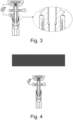
- Fig. 3 shows an example of a 4-point measurement on tip according to an exemplary embodiment of the present invention.
- Measurement on the tip of the female contact are shown in Fig. 3 according to an exemplary embodiment of the present invention.
- a dedicated surface on the male contact would be required in this case.
- Fig. 4 shows an example of a 4-point measurement setup according to an exemplary embodiment of the present invention.
- Fig. 5 shows an example of a 4-point measurement setup in any location according to an exemplary embodiment of the present invention according to an exemplary embodiment of the present invention.
- Measurement by connecting the voltage measurement in any location of the electrical path of the withdrawable module. Ideally the electrical connection will be accessible from front of the withdrawable module Fig. 5 .
- the entire device is in-line with a force sensor and a position sensor which enables a force vs. position measurement.
- Fig. 6 shows an example of a sectional view of test device according to an exemplary embodiment of the present invention.
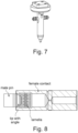
- Fig. 7 shows an example of a test device according to an exemplary embodiment of the present invention.
- the spring loaded current probe is T-shaped, so that the required electrical connection can be done.
- Fig. 7 shows the CAD model of the test device.
- Fig. 8 shows an overview of an example of a contact device according to an exemplary embodiment of the present invention.
- Fig. 8 gives an overview of the contact device, including male pin and its tip, the contact lamella and the female contact part.
- Fig. 9 shows an example of a diagram of force over position according to an exemplary embodiment of the present invention.
- Fig. 9 shows various positions.
- Position 4 Mal pin enters the lower part of the female contact and gets centered.
- Position 5 Male pin comes in direct contact to the female contact and movement gets stopped.
- Fig. 10 shows various areas of the sliding force vs. position curve several information according to an exemplary embodiment of the present invention.
- Fig. 10 gives an example for area analysis.
- Fig. 10 gives an example for determination and identification of different positions:
- the measurement of the forces on the inbound and outbound section need to be equal and can be used to define the zero level of the sliding force.
- a deviation in the inbound and outbound force measurement indicates a drift of the force sensor used for force measurement. Thus, it can be used to check the quality of the measurement. Furthermore, this information may be used to compensate the drift.
- the maximum force on the inbound section precisely defines the starting location of the lamella (Area B1) and the end location of the lamella (Area B2). From the stopping position the depth of the contact may be determined (Area B3). This information about the physical dimensions of the contact may be used to identify the contact type and additional specifications.
- Area B1 At this position the male pin enters the lamella and deforms the lamella. Therefore, the radial force F r can be extracted from this measurement if an appropriate model is used which contains the velocity, dimensional parameters of the tip of the male pin as well as the material parameters of the male pin's tip.
- Area C The sliding force can be deduced from this measurement section. Comparison of data from Area C and Area D may be used to determine if the male contact is well centered. Here only single mechanical guidance which is located before the lamella.
- Area D The sliding force can be deduced from the measurement section. Comparison of data from Area C and Area D may be used to determine if the male contact is well centered. Here double mechanical guidance which are located before and behind the lamella.
- the curves measured in section C and D on the inbound and outbound section may be further analyzed.
- the mean value is an indication of contact force and the fluctuation is a measure for contact roughness.
- the contacting surfaces are both metallic.
- At least one measurement of the electrical contact resistance can be performed.
- the information from the force vs. position measurement can be used to trigger the contact resistance measurement(s). More than one contact resistance measurement may be done to achieve higher statistics or to measure the contact resistance at a certain contact force.
Landscapes
- Physics & Mathematics (AREA)
- General Physics & Mathematics (AREA)
- Engineering & Computer Science (AREA)
- Theoretical Computer Science (AREA)
- Measurement Of Resistance Or Impedance (AREA)
Description
- The present invention relates a test device for inspection tasks of female contacts in LV switchgears. In particular, the present invention relates to a contact measurement system and method for measuring a parameter of a contact of a switchgear
-
WO 2006/048381 A1 describes a monitoring method for a by relatively movable contact pieces: a separation path of an electric switching device, which is defined by two contact pieces which can be displaced in relation to each other. - As the female and male contacts of a switchgear are prone to electrical and mechanical wear, it is required to inspect them in planned service intervals. Therefore, a testing method is required to deduce the contact condition.
- Mainly the female contact needs to be inspected as this contact includes a lamella which ensures good electrical conduction.
- Two main parameters of interest are:
The electrical resistance as well as the contact force. Too high electrical resistance will lead to electrical loss and excessive heat generation. A low contact force will lead to a poor contact performance during short circuit events as the high forces during such an event may lead to physical separation of the contact, thus leading to arcing. - As a secondary effect of too low contact force is an increase of contact resistance. There is a need to address these issues.
- Therefore, it would be advantageous to have an improved technique to measure the contacts of a switchgear.
- The object of the present invention is solved with the subject matter of the independent claims, wherein further embodiments are incorporated in the dependent claims.
- In a first aspect, there is provided a contact measurement system for measuring a parameter of a contact of a switchgear, comprising a first device configured to measure an electrical resistance of the contact and to map the electrical resistance spatially and/or dynamically; a second device configured to measure an axial force of the contact and to map the axial force spatially and/or dynamically; and a third device configured to measure a position of the contact; wherein the contact measurement system is configured to determine a position-depending force characteristic based on the measured axial force of the contact and the position of the contact; wherein the contact measurement system is configured to determine a status of the contact based on a combination of the position-depending force characteristic with the electrical resistance of the contact.
- In this manner a test device is provided that enables that although according to the state-of-the-art the contact condition is monitored by measuring the peak sliding force when withdrawing the male contact from the connection and improved measurement is enabled. The condition of any contact can be defined by three separate measurements: Visual inspection, resistance measurements and contact force measurement. The present measurement system allows for an integrated and thereby combined measurement of electrical resistance, axial force and position.
- In this manner a test device is provided that enables measurements for contact quality: combine measurement of sliding force in relation to position with measurement of electrical resistance.
- The present invention enables to give an indication of contact quality; lubrication, ageing and contamination due to site conditions has effect on the contact quality and the effect of lubrication, ageing and contamination due to site conditions on contact quality will be recognized by combining measurement of sliding force in relation to position with measurement of electrical resistance.
- Thereby a position depending force characteristic can be derived. The combination of resistance and force/position characteristics allows for a suitable on-site inspection of the lamella and a general status of the present condition.
- The solution proposed also maps the contact forces (sliding force or radial force) dynamically, i.e. versus position while inserting and/or withdrawing a male test pin.
- The test pin resembles the pin used in a medium voltage switchgear but may have adoptions to support the measurement. The performance of the contact during operation is mainly determined by the radial force.
- In a second aspect, there is provided a method is disclosed which allows to extract various information on the contact condition from this dynamic measurement.
- The second aspect of the present invention relates to a contact measurement method for measuring a parameter of a contact of a switchgear, the method comprising the steps of: measuring an electrical resistance of the contact and mapping the electrical resistance spatially and/or dynamically by means of a first device; measuring an axial force of the contact and to map the axial force spatially and/or dynamically by means of a second device; and measuring a position of the contact by means of third device; wherein the method further comprising the step of determining a position-depending force characteristic based on the measured axial force of the contact and the position of the contact; wherein the method further comprising the step of determining a status of the contact based on a combination of the position-depending force characteristic with the electrical resistance of the contact.
- In an example, this method may be combined with a measurement of contact resistance.
- To provide an electrical current flow conventionally two bodies are mechanically joined. In some applications dedicated lamellas are built-in to provide a good electrical contact.
- Depending on e.g. switching cycles, current transfer duration, overcurrent's by external malfunctions such as short circuits these lamellas might be worn or damaged.
- In other words, the present invention on is about a test method to deduce the condition of such a female electrical contact e.g. with lamella contact.
- In an exemplary embodiment of the present invention, the contact measurement system is configured to scan a surface of the switch gear.
- In an exemplary embodiment of the present invention, the contact is a female or a male contact.
- In an exemplary embodiment of the present invention, the contact is measured on a built-in component of the switchgear.
- In an exemplary embodiment of the present invention, the contact measurement system is portable.
- In an exemplary embodiment of the present invention, the contact measurement system is non-portable.
- In an exemplary embodiment of the present invention, the contact measurement system comprises a hollow surrounding shaft, that contains an electrical isolated pin and which is used by the first device for measuring the electrical resistance of the contact.
- In an exemplary embodiment of the present invention, the first device for measuring the electrical resistance comprises a 4-point measurement setup.
- In an exemplary embodiment of the present invention, the first device for measuring the electrical resistance comprises a 3-point measurement setup.
- In an exemplary embodiment of the present invention, the first device is configured to perform a measurement of the electrical resistance by connecting a voltage measurement in any location of an electrical path of a withdrawable module.
- In an exemplary embodiment of the present invention, the third device configured to be switched-off in a suspend mode and wherein the contact measurement system is configured to determine a force characteristic based on the measured axial force of the contact; wherein the contact measurement system is configured to determine a status of the contact based on a combination of force characteristic with the electrical resistance of the contact.
- The above aspects and examples will become apparent from and be elucidated with reference to the embodiments described hereinafter.
- Exemplary embodiments will be described in the following with reference to the following drawings:
-
Fig. 1 shows a schematic illustration of a concept of 4 point measurement according to an exemplary embodiment of the present invention; -
Fig. 2 shows an example of a 4-point measurement setup on outside according to an exemplary embodiment of the present invention; -
Fig. 3 shows an example of a 4-point measurement on tip according to an exemplary embodiment of the present invention; -
Fig. 4 shows an example of a 4-point measurement setup according to an exemplary embodiment of the present invention; -
Fig. 5 shows an example of a 4-point measurement setup in any location according to an exemplary embodiment of the present invention according to an exemplary embodiment of the present invention; -
Fig. 6 shows an example of a sectional view of test device according to an exemplary embodiment of the present invention; -
Fig. 7 shows an example of a test device according to an exemplary embodiment of the present invention; -
Fig. 8 shows an overview of an example of a contact device according to an exemplary embodiment of the present invention; -
Fig. 9 shows an example of a diagram of force over position according to an exemplary embodiment of the present invention; -
Fig. 10 shows various areas of the sliding force vs. position curve several information according to an exemplary embodiment of the present invention; -
Fig. 1 shows the general schematic of the developed test device according to an exemplary embodiment of the present invention. The test device may comprise a hollow surrounding shaft that contains an electrical isolated pin. The red component in the schematic is the component of interest. - With a 4-point measurement setup, the resistance of the red device can directly be measured. The mid pin is spring loaded to provide a sufficiently good current transfer to the female contact. Alternatively, a 3-point measurement may be used as the electrical connection of current source and voltage measurement to the pin can be defined during construction of the test device.
- For the voltage measurement on the female contact (blue component in
Fig. 1 ) several alternative options can be used:
Measurement on the outside of the female contact are shown inFig. 2 according to an exemplary embodiment of the present invention. A modification to the insulating cover of the female contact would be required in this case. -
Fig. 2 shows an example of a 4-point measurement setup on outside according to an exemplary embodiment of the present invention. - In an exemplary embodiment, the voltage measurement may also be performed using the middle pin as shown in
Fig. 2 . - Measurement on the LV switchgear installation which is not shown in
Fig. 1 . The advantage would be simple access without need to modify the insulating cover -
Fig. 3 shows an example of a 4-point measurement on tip according to an exemplary embodiment of the present invention. - Measurement on the tip of the female contact are shown in
Fig. 3 according to an exemplary embodiment of the present invention. A dedicated surface on the male contact would be required in this case. -
Fig. 4 shows an example of a 4-point measurement setup according to an exemplary embodiment of the present invention. - Measurement by a third electrical pin running within the pin are shown in
Fig. 4 according to an exemplary embodiment of the present invention. -
Fig. 5 shows an example of a 4-point measurement setup in any location according to an exemplary embodiment of the present invention according to an exemplary embodiment of the present invention. - Measurement by connecting the voltage measurement in any location of the electrical path of the withdrawable module. Ideally the electrical connection will be accessible from front of the withdrawable module
Fig. 5 . - As a second physical measure the axial (sliding) force while insertion or pull-out is of interest. Therefore, the entire device is in-line with a force sensor and a position sensor which enables a force vs. position measurement.
-
Fig. 6 shows an example of a sectional view of test device according to an exemplary embodiment of the present invention. -
Fig. 7 shows an example of a test device according to an exemplary embodiment of the present invention. - To allow for an in-line assembly, the spring loaded current probe is T-shaped, so that the required electrical connection can be done.
Fig. 7 shows the CAD model of the test device. -
Fig. 8 shows an overview of an example of a contact device according to an exemplary embodiment of the present invention. -
Fig. 8 gives an overview of the contact device, including male pin and its tip, the contact lamella and the female contact part. -
Fig. 9 shows an example of a diagram of force over position according to an exemplary embodiment of the present invention. -
Fig. 9 shows various positions. - Position 1: Male pin is outside of the female contact
- Position 2: Tip of the male pin starts to enter the female contact
- Position 3: Male pin enters the lamella. High force is required to deform the lamella at the beginning.
- After this initial deformation the sliding force levels on a lower value.
- Position 4: Mal pin enters the lower part of the female contact and gets centered.
- Position 5: Male pin comes in direct contact to the female contact and movement gets stopped.
-
Fig. 10 shows various areas of the sliding force vs. position curve several information according to an exemplary embodiment of the present invention. -
Fig. 10 gives an example for area analysis. -
Fig. 10 gives an example for determination and identification of different positions: - The measurement of the forces on the inbound and outbound section need to be equal and can be used to define the zero level of the sliding force. A deviation in the inbound and outbound force measurement indicates a drift of the force sensor used for force measurement. Thus, it can be used to check the quality of the measurement. Furthermore, this information may be used to compensate the drift.
- The maximum force on the inbound section precisely defines the starting location of the lamella (Area B1) and the end location of the lamella (Area B2). From the stopping position the depth of the contact may be determined (Area B3). This information about the physical dimensions of the contact may be used to identify the contact type and additional specifications.
- Area B1: At this position the male pin enters the lamella and deforms the lamella. Therefore, the radial force Fr can be extracted from this measurement if an appropriate model is used which contains the velocity, dimensional parameters of the tip of the male pin as well as the material parameters of the male pin's tip.
- Area C: The sliding force can be deduced from this measurement section. Comparison of data from Area C and Area D may be used to determine if the male contact is well centered. Here only single mechanical guidance which is located before the lamella.
- Area D: The sliding force can be deduced from the measurement section. Comparison of data from Area C and Area D may be used to determine if the male contact is well centered. Here double mechanical guidance which are located before and behind the lamella.
- The curves measured in section C and D on the inbound and outbound section may be further analyzed. The mean value is an indication of contact force and the fluctuation is a measure for contact roughness. In general, the sliding force and radial force are connected via the coefficient of friction µ, according to Fs=µ Fr. The contacting surfaces are both metallic.
- During the above measurement at least one measurement of the electrical contact resistance can be performed. The information from the force vs. position measurement can be used to trigger the contact resistance measurement(s). More than one contact resistance measurement may be done to achieve higher statistics or to measure the contact resistance at a certain contact force.
- While the invention has been illustrated and described in detail in the drawings and foregoing description, such illustration and description are to be considered illustrative or exemplary and not restrictive. The invention is not limited to the disclosed embodiments. Other variations to the disclosed embodiments can be understood and effected by those skilled in the art in practicing the claimed invention, from a study of the drawings, the disclosure, and the dependent claims.
Claims (12)
- A contact measurement system for measuring a parameter of a contact of a switchgear, comprising:a first device configured to measure an electrical resistance of the contact and to map the electrical resistance spatially and/or dynamically;a second device configured to measure an axial force of the contact and to map the axial force spatially and/or dynamically; anda third device configured to measure a position of the contact;wherein the contact measurement system is configured to determine a position-depending force characteristic based on the measured axial force of the contact and the position of the contact; wherein the contact measurement system is configured to determine a status of the contact based on a combination of the position-depending force characteristic with the electrical resistance of the contact.
- The contact measurement system according to claim 1, wherein the contact measurements system is configured to scan a surface of the switch gear.
- The contact measurement system according to any one of claims 1 - 2, wherein the contact is a female contact or a male contact.
- The contact measurement system according to any one of claims 1 - 3, wherein the contact is a built-in component of the switchgear.
- The contact measurement system according to any one of claims 1 - 4, wherein the contact measurement system is portable.
- The contact measurement system according to any one of claims 1 - 5, wherein the contact measurement system is non-portable.
- The contact measurement system according to any one of claims 1 - 6, wherein the contact measurement system comprises a hollow surrounding shaft, that contains an electrical isolated pin and which is used by the first device for measuring the electrical resistance of the contact.
- The contact measurement system according to any one of claims 1 - 7, wherein the first device for measuring the electrical resistance comprises a 4-point measurement setup.
- The contact measurement system according to any one of claims 1 - 8, wherein the first device for measuring the electrical resistance comprises a 3-point measurement setup.
- The contact measurement system according to any one of claims 1 - 9, wherein the first device is configured to perform a measurement of the electrical resistance by connecting a voltage measurement in any location of an electrical path of a withdrawable module.
- The contact measurement system according to any one of claims 1 - 10, wherein the third device configured to be switched-off in a suspend mode and wherein the contact measurement system is configured to determine a force characteristic based on the measured axial force of the contact; wherein the contact measurement system is configured to determine a status of the contact based on a combination of force characteristic with the electrical resistance of the contact.
- A contact measurement method for measuring a parameter of a contact of a switchgear, the method comprising the steps of:- measuring (S1) an electrical resistance of the contact and mapping the electrical resistance spatially and/or dynamically by means of a first device;measuring (S2) an axial force of the contact and to map the axial force spatially and/or dynamically by means of a second device; andmeasuring (S2) a position of the contact by means of third device;wherein the method further comprising the step of determining a position-depending force characteristic based on the measured axial force of the contact and the position of the contact; wherein the method further comprising the step of determining a status of the contact based on a combination of the position-depending force characteristic with the electrical resistance of the contact.
Priority Applications (3)
| Application Number | Priority Date | Filing Date | Title |
|---|---|---|---|
| EP20182201.2A EP3929604B1 (en) | 2020-06-25 | 2020-06-25 | A contact measurement system and method for measuring a parameter of a contact of a switchgear |
| US17/355,211 US11668753B2 (en) | 2020-06-25 | 2021-06-23 | Contact measurement system and method for measuring a parameter of a contact of a switchgear |
| CN202110707649.7A CN113848465B (en) | 2020-06-25 | 2021-06-25 | Contact measurement system and method for measuring parameters of contacts of a switchgear |
Applications Claiming Priority (1)
| Application Number | Priority Date | Filing Date | Title |
|---|---|---|---|
| EP20182201.2A EP3929604B1 (en) | 2020-06-25 | 2020-06-25 | A contact measurement system and method for measuring a parameter of a contact of a switchgear |
Publications (2)
| Publication Number | Publication Date |
|---|---|
| EP3929604A1 EP3929604A1 (en) | 2021-12-29 |
| EP3929604B1 true EP3929604B1 (en) | 2024-07-31 |
Family
ID=71143654
Family Applications (1)
| Application Number | Title | Priority Date | Filing Date |
|---|---|---|---|
| EP20182201.2A Active EP3929604B1 (en) | 2020-06-25 | 2020-06-25 | A contact measurement system and method for measuring a parameter of a contact of a switchgear |
Country Status (3)
| Country | Link |
|---|---|
| US (1) | US11668753B2 (en) |
| EP (1) | EP3929604B1 (en) |
| CN (1) | CN113848465B (en) |
Families Citing this family (1)
| Publication number | Priority date | Publication date | Assignee | Title |
|---|---|---|---|---|
| CN119738699B (en) * | 2024-11-27 | 2026-02-06 | 国网福建省电力有限公司 | A testing device for simulating contact plate operating conditions |
Family Cites Families (14)
| Publication number | Priority date | Publication date | Assignee | Title |
|---|---|---|---|---|
| DE1901965B2 (en) * | 1969-01-16 | 1972-05-18 | Heddernheimer Metallwarenfabrik Ag, Werk Fluorn, 7239 Fluorn | SWITCHING CONTACT FOR RELAYS, SWITCHES, KEYS OR THE LIKE. |
| JP3231735B2 (en) * | 1999-05-07 | 2001-11-26 | 大分日本電気株式会社 | IC socket contact method |
| DE102004053612A1 (en) * | 2004-11-02 | 2006-05-04 | Siemens Ag | Monitoring method for a limited by relatively movable contact pieces separation distance of an electrical switching device and associated apparatus for carrying out the monitoring method |
| DE102007058989A1 (en) * | 2007-12-07 | 2009-06-18 | Siemens Ag | Residual current circuit breaker and method for performing a self-test of a residual current circuit breaker |
| US8174276B2 (en) * | 2008-05-22 | 2012-05-08 | Texas Instruments Incorporated | Coaxial four-point probe for low resistance measurements |
| JP5418877B2 (en) * | 2008-11-04 | 2014-02-19 | 株式会社国際電気セミコンダクターサービス | 4 probe resistivity measuring device |
| GB0820415D0 (en) | 2008-11-07 | 2008-12-17 | Ea Tech Ltd | Improvements in or relating to industrial circuit breakers (MCB) |
| FR2945661A1 (en) * | 2009-05-18 | 2010-11-19 | Schneider Electric Ind Sas | EVALUATION OF THE WEAR OF CONTACTS ENFONCES BY THE VARIATION OF THE ROTATION OF THE TREE OF POLES |
| WO2013094354A1 (en) * | 2011-12-20 | 2013-06-27 | 三菱電機株式会社 | Vacuum switchgear with vacuum-degradation detection device, and method for detecting vacuum degradation of vacuum switchgear |
| FR3011673B1 (en) * | 2013-10-08 | 2015-12-11 | Schneider Electric Ind Sas | SWITCHING DEVICE AND METHOD FOR DETECTING A FAULT IN SUCH A SWITCHING DEVICE |
| EP3073049A1 (en) * | 2015-03-26 | 2016-09-28 | Siemens Aktiengesellschaft | Method for determining an operational state of a subsea connector unit |
| KR101673902B1 (en) * | 2015-05-11 | 2016-11-22 | 박지영 | A tulip and clip fitting plug of test equipment for the contacting device of circuit breaker |
| KR101673903B1 (en) * | 2016-10-17 | 2016-11-22 | 박지영 | A tulip and clip fitting plug of test equipment for the contacting device of circuit breaker |
| EP3598256B1 (en) * | 2018-07-16 | 2023-11-29 | ABB Schweiz AG | Apparatus for prediction of the residual lifetime of an electrical system |
-
2020
- 2020-06-25 EP EP20182201.2A patent/EP3929604B1/en active Active
-
2021
- 2021-06-23 US US17/355,211 patent/US11668753B2/en active Active
- 2021-06-25 CN CN202110707649.7A patent/CN113848465B/en active Active
Also Published As
| Publication number | Publication date |
|---|---|
| US20210405115A1 (en) | 2021-12-30 |
| CN113848465A (en) | 2021-12-28 |
| EP3929604A1 (en) | 2021-12-29 |
| US11668753B2 (en) | 2023-06-06 |
| CN113848465B (en) | 2024-12-27 |
Similar Documents
| Publication | Publication Date | Title |
|---|---|---|
| US20240369420A1 (en) | Temperature measuring structure, charging device, and motor vehicle | |
| US11380933B2 (en) | Safety test method for determination of critical cell states by internal short provocation | |
| US11668753B2 (en) | Contact measurement system and method for measuring a parameter of a contact of a switchgear | |
| EP2803989A1 (en) | Electrode testing method and electrode testing apparatus | |
| CN106771665A (en) | A kind of gas insulated bus junction contacts condition checkout gear and method | |
| WO2020017693A1 (en) | Apparatus for automatically determining failure type of transformer | |
| CN210181145U (en) | Charging gun usability testing system and testing machine | |
| CN104481608B (en) | Temperature measuring equipment, whirlpool oar aero-engine and thermometry | |
| JP2016090495A (en) | Withstand voltage test device, insulation resistance test device, and connection status confirmation circuit | |
| US10663421B2 (en) | Mineral insulated sheathed assembly with insulation resistance indicator | |
| CN211043578U (en) | Semiconductor test box with temperature control function | |
| CN119224556A (en) | Vacuum circuit breaker time characteristic detection system and method based on transient electrical signal | |
| CN111504629A (en) | Alternative test method for traditional type test of electronic connector | |
| US12259439B2 (en) | Voltage tap for measuring a voltage | |
| JP4539530B2 (en) | Motor insulation inspection device | |
| CN210833673U (en) | Combined sensor for online monitoring, transformation and upgrading of in-service rotating machinery | |
| CN212626189U (en) | Terminal connector | |
| CN224053074U (en) | Isolation switch | |
| JP2019086491A (en) | Continuity inspection jig | |
| US20160209237A1 (en) | Sensor simulator and system for testing rotatable sensor signal transmitters | |
| CN217278621U (en) | Insulation resistance detection device that opens a way | |
| JP7786678B2 (en) | Specimen deterioration detection device and detection method | |
| CN223538973U (en) | Offline detection tool for inter-turn short circuit faults in turbine generator rotor windings | |
| CN112345096B (en) | Movable temperature probe device | |
| JPS6358269A (en) | Method and device for electrically measuring electromechanical relay armature excess movement |
Legal Events
| Date | Code | Title | Description |
|---|---|---|---|
| PUAI | Public reference made under article 153(3) epc to a published international application that has entered the european phase |
Free format text: ORIGINAL CODE: 0009012 |
|
| STAA | Information on the status of an ep patent application or granted ep patent |
Free format text: STATUS: THE APPLICATION HAS BEEN PUBLISHED |
|
| AK | Designated contracting states |
Kind code of ref document: A1 Designated state(s): AL AT BE BG CH CY CZ DE DK EE ES FI FR GB GR HR HU IE IS IT LI LT LU LV MC MK MT NL NO PL PT RO RS SE SI SK SM TR |
|
| B565 | Issuance of search results under rule 164(2) epc |
Effective date: 20201204 |
|
| STAA | Information on the status of an ep patent application or granted ep patent |
Free format text: STATUS: REQUEST FOR EXAMINATION WAS MADE |
|
| 17P | Request for examination filed |
Effective date: 20220624 |
|
| RBV | Designated contracting states (corrected) |
Designated state(s): AL AT BE BG CH CY CZ DE DK EE ES FI FR GB GR HR HU IE IS IT LI LT LU LV MC MK MT NL NO PL PT RO RS SE SI SK SM TR |
|
| GRAP | Despatch of communication of intention to grant a patent |
Free format text: ORIGINAL CODE: EPIDOSNIGR1 |
|
| STAA | Information on the status of an ep patent application or granted ep patent |
Free format text: STATUS: GRANT OF PATENT IS INTENDED |
|
| RIC1 | Information provided on ipc code assigned before grant |
Ipc: H01H 1/00 20060101ALI20240130BHEP Ipc: G01R 31/327 20060101AFI20240130BHEP |
|
| INTG | Intention to grant announced |
Effective date: 20240213 |
|
| GRAS | Grant fee paid |
Free format text: ORIGINAL CODE: EPIDOSNIGR3 |
|
| GRAA | (expected) grant |
Free format text: ORIGINAL CODE: 0009210 |
|
| STAA | Information on the status of an ep patent application or granted ep patent |
Free format text: STATUS: THE PATENT HAS BEEN GRANTED |
|
| AK | Designated contracting states |
Kind code of ref document: B1 Designated state(s): AL AT BE BG CH CY CZ DE DK EE ES FI FR GB GR HR HU IE IS IT LI LT LU LV MC MK MT NL NO PL PT RO RS SE SI SK SM TR |
|
| REG | Reference to a national code |
Ref country code: CH Ref legal event code: EP Ref country code: GB Ref legal event code: FG4D |
|
| REG | Reference to a national code |
Ref country code: DE Ref legal event code: R096 Ref document number: 602020034744 Country of ref document: DE |
|
| REG | Reference to a national code |
Ref country code: IE Ref legal event code: FG4D |
|
| REG | Reference to a national code |
Ref country code: LT Ref legal event code: MG9D |
|
| REG | Reference to a national code |
Ref country code: NL Ref legal event code: MP Effective date: 20240731 |
|
| PG25 | Lapsed in a contracting state [announced via postgrant information from national office to epo] |
Ref country code: PT Free format text: LAPSE BECAUSE OF FAILURE TO SUBMIT A TRANSLATION OF THE DESCRIPTION OR TO PAY THE FEE WITHIN THE PRESCRIBED TIME-LIMIT Effective date: 20241202 |
|
| REG | Reference to a national code |
Ref country code: AT Ref legal event code: MK05 Ref document number: 1708957 Country of ref document: AT Kind code of ref document: T Effective date: 20240731 |
|
| PG25 | Lapsed in a contracting state [announced via postgrant information from national office to epo] |
Ref country code: PT Free format text: LAPSE BECAUSE OF FAILURE TO SUBMIT A TRANSLATION OF THE DESCRIPTION OR TO PAY THE FEE WITHIN THE PRESCRIBED TIME-LIMIT Effective date: 20241202 |
|
| PG25 | Lapsed in a contracting state [announced via postgrant information from national office to epo] |
Ref country code: NO Free format text: LAPSE BECAUSE OF FAILURE TO SUBMIT A TRANSLATION OF THE DESCRIPTION OR TO PAY THE FEE WITHIN THE PRESCRIBED TIME-LIMIT Effective date: 20241031 |
|
| PG25 | Lapsed in a contracting state [announced via postgrant information from national office to epo] |
Ref country code: NL Free format text: LAPSE BECAUSE OF FAILURE TO SUBMIT A TRANSLATION OF THE DESCRIPTION OR TO PAY THE FEE WITHIN THE PRESCRIBED TIME-LIMIT Effective date: 20240731 Ref country code: FI Free format text: LAPSE BECAUSE OF FAILURE TO SUBMIT A TRANSLATION OF THE DESCRIPTION OR TO PAY THE FEE WITHIN THE PRESCRIBED TIME-LIMIT Effective date: 20240731 Ref country code: PL Free format text: LAPSE BECAUSE OF FAILURE TO SUBMIT A TRANSLATION OF THE DESCRIPTION OR TO PAY THE FEE WITHIN THE PRESCRIBED TIME-LIMIT Effective date: 20240731 Ref country code: GR Free format text: LAPSE BECAUSE OF FAILURE TO SUBMIT A TRANSLATION OF THE DESCRIPTION OR TO PAY THE FEE WITHIN THE PRESCRIBED TIME-LIMIT Effective date: 20241101 |
|
| PG25 | Lapsed in a contracting state [announced via postgrant information from national office to epo] |
Ref country code: BG Free format text: LAPSE BECAUSE OF FAILURE TO SUBMIT A TRANSLATION OF THE DESCRIPTION OR TO PAY THE FEE WITHIN THE PRESCRIBED TIME-LIMIT Effective date: 20240731 |
|
| PG25 | Lapsed in a contracting state [announced via postgrant information from national office to epo] |
Ref country code: LV Free format text: LAPSE BECAUSE OF FAILURE TO SUBMIT A TRANSLATION OF THE DESCRIPTION OR TO PAY THE FEE WITHIN THE PRESCRIBED TIME-LIMIT Effective date: 20240731 |
|
| PG25 | Lapsed in a contracting state [announced via postgrant information from national office to epo] |
Ref country code: IS Free format text: LAPSE BECAUSE OF FAILURE TO SUBMIT A TRANSLATION OF THE DESCRIPTION OR TO PAY THE FEE WITHIN THE PRESCRIBED TIME-LIMIT Effective date: 20241130 Ref country code: AT Free format text: LAPSE BECAUSE OF FAILURE TO SUBMIT A TRANSLATION OF THE DESCRIPTION OR TO PAY THE FEE WITHIN THE PRESCRIBED TIME-LIMIT Effective date: 20240731 |
|
| PG25 | Lapsed in a contracting state [announced via postgrant information from national office to epo] |
Ref country code: HR Free format text: LAPSE BECAUSE OF FAILURE TO SUBMIT A TRANSLATION OF THE DESCRIPTION OR TO PAY THE FEE WITHIN THE PRESCRIBED TIME-LIMIT Effective date: 20240731 |
|
| PG25 | Lapsed in a contracting state [announced via postgrant information from national office to epo] |
Ref country code: RS Free format text: LAPSE BECAUSE OF FAILURE TO SUBMIT A TRANSLATION OF THE DESCRIPTION OR TO PAY THE FEE WITHIN THE PRESCRIBED TIME-LIMIT Effective date: 20241031 Ref country code: ES Free format text: LAPSE BECAUSE OF FAILURE TO SUBMIT A TRANSLATION OF THE DESCRIPTION OR TO PAY THE FEE WITHIN THE PRESCRIBED TIME-LIMIT Effective date: 20240731 |
|
| PG25 | Lapsed in a contracting state [announced via postgrant information from national office to epo] |
Ref country code: RS Free format text: LAPSE BECAUSE OF FAILURE TO SUBMIT A TRANSLATION OF THE DESCRIPTION OR TO PAY THE FEE WITHIN THE PRESCRIBED TIME-LIMIT Effective date: 20241031 Ref country code: PL Free format text: LAPSE BECAUSE OF FAILURE TO SUBMIT A TRANSLATION OF THE DESCRIPTION OR TO PAY THE FEE WITHIN THE PRESCRIBED TIME-LIMIT Effective date: 20240731 Ref country code: NO Free format text: LAPSE BECAUSE OF FAILURE TO SUBMIT A TRANSLATION OF THE DESCRIPTION OR TO PAY THE FEE WITHIN THE PRESCRIBED TIME-LIMIT Effective date: 20241031 Ref country code: NL Free format text: LAPSE BECAUSE OF FAILURE TO SUBMIT A TRANSLATION OF THE DESCRIPTION OR TO PAY THE FEE WITHIN THE PRESCRIBED TIME-LIMIT Effective date: 20240731 Ref country code: LV Free format text: LAPSE BECAUSE OF FAILURE TO SUBMIT A TRANSLATION OF THE DESCRIPTION OR TO PAY THE FEE WITHIN THE PRESCRIBED TIME-LIMIT Effective date: 20240731 Ref country code: IS Free format text: LAPSE BECAUSE OF FAILURE TO SUBMIT A TRANSLATION OF THE DESCRIPTION OR TO PAY THE FEE WITHIN THE PRESCRIBED TIME-LIMIT Effective date: 20241130 Ref country code: HR Free format text: LAPSE BECAUSE OF FAILURE TO SUBMIT A TRANSLATION OF THE DESCRIPTION OR TO PAY THE FEE WITHIN THE PRESCRIBED TIME-LIMIT Effective date: 20240731 Ref country code: GR Free format text: LAPSE BECAUSE OF FAILURE TO SUBMIT A TRANSLATION OF THE DESCRIPTION OR TO PAY THE FEE WITHIN THE PRESCRIBED TIME-LIMIT Effective date: 20241101 Ref country code: FI Free format text: LAPSE BECAUSE OF FAILURE TO SUBMIT A TRANSLATION OF THE DESCRIPTION OR TO PAY THE FEE WITHIN THE PRESCRIBED TIME-LIMIT Effective date: 20240731 Ref country code: ES Free format text: LAPSE BECAUSE OF FAILURE TO SUBMIT A TRANSLATION OF THE DESCRIPTION OR TO PAY THE FEE WITHIN THE PRESCRIBED TIME-LIMIT Effective date: 20240731 Ref country code: BG Free format text: LAPSE BECAUSE OF FAILURE TO SUBMIT A TRANSLATION OF THE DESCRIPTION OR TO PAY THE FEE WITHIN THE PRESCRIBED TIME-LIMIT Effective date: 20240731 Ref country code: AT Free format text: LAPSE BECAUSE OF FAILURE TO SUBMIT A TRANSLATION OF THE DESCRIPTION OR TO PAY THE FEE WITHIN THE PRESCRIBED TIME-LIMIT Effective date: 20240731 |
|
| PG25 | Lapsed in a contracting state [announced via postgrant information from national office to epo] |
Ref country code: DK Free format text: LAPSE BECAUSE OF FAILURE TO SUBMIT A TRANSLATION OF THE DESCRIPTION OR TO PAY THE FEE WITHIN THE PRESCRIBED TIME-LIMIT Effective date: 20240731 Ref country code: RO Free format text: LAPSE BECAUSE OF FAILURE TO SUBMIT A TRANSLATION OF THE DESCRIPTION OR TO PAY THE FEE WITHIN THE PRESCRIBED TIME-LIMIT Effective date: 20240731 Ref country code: SM Free format text: LAPSE BECAUSE OF FAILURE TO SUBMIT A TRANSLATION OF THE DESCRIPTION OR TO PAY THE FEE WITHIN THE PRESCRIBED TIME-LIMIT Effective date: 20240731 |
|
| PG25 | Lapsed in a contracting state [announced via postgrant information from national office to epo] |
Ref country code: EE Free format text: LAPSE BECAUSE OF FAILURE TO SUBMIT A TRANSLATION OF THE DESCRIPTION OR TO PAY THE FEE WITHIN THE PRESCRIBED TIME-LIMIT Effective date: 20240731 |
|
| PG25 | Lapsed in a contracting state [announced via postgrant information from national office to epo] |
Ref country code: CZ Free format text: LAPSE BECAUSE OF FAILURE TO SUBMIT A TRANSLATION OF THE DESCRIPTION OR TO PAY THE FEE WITHIN THE PRESCRIBED TIME-LIMIT Effective date: 20240731 |
|
| PG25 | Lapsed in a contracting state [announced via postgrant information from national office to epo] |
Ref country code: SK Free format text: LAPSE BECAUSE OF FAILURE TO SUBMIT A TRANSLATION OF THE DESCRIPTION OR TO PAY THE FEE WITHIN THE PRESCRIBED TIME-LIMIT Effective date: 20240731 |
|
| REG | Reference to a national code |
Ref country code: DE Ref legal event code: R097 Ref document number: 602020034744 Country of ref document: DE |
|
| PLBE | No opposition filed within time limit |
Free format text: ORIGINAL CODE: 0009261 |
|
| STAA | Information on the status of an ep patent application or granted ep patent |
Free format text: STATUS: NO OPPOSITION FILED WITHIN TIME LIMIT |
|
| 26N | No opposition filed |
Effective date: 20250501 |
|
| PGFP | Annual fee paid to national office [announced via postgrant information from national office to epo] |
Ref country code: DE Payment date: 20250618 Year of fee payment: 6 |
|
| PGFP | Annual fee paid to national office [announced via postgrant information from national office to epo] |
Ref country code: GB Payment date: 20250618 Year of fee payment: 6 |
|
| PGFP | Annual fee paid to national office [announced via postgrant information from national office to epo] |
Ref country code: FR Payment date: 20250627 Year of fee payment: 6 |
|
| PG25 | Lapsed in a contracting state [announced via postgrant information from national office to epo] |
Ref country code: SE Free format text: LAPSE BECAUSE OF FAILURE TO SUBMIT A TRANSLATION OF THE DESCRIPTION OR TO PAY THE FEE WITHIN THE PRESCRIBED TIME-LIMIT Effective date: 20240731 |
|
| PGFP | Annual fee paid to national office [announced via postgrant information from national office to epo] |
Ref country code: IT Payment date: 20250624 Year of fee payment: 6 |
|
| REG | Reference to a national code |
Ref country code: CH Ref legal event code: H13 Free format text: ST27 STATUS EVENT CODE: U-0-0-H10-H13 (AS PROVIDED BY THE NATIONAL OFFICE) Effective date: 20260127 |
|
| PG25 | Lapsed in a contracting state [announced via postgrant information from national office to epo] |
Ref country code: MC Free format text: LAPSE BECAUSE OF FAILURE TO SUBMIT A TRANSLATION OF THE DESCRIPTION OR TO PAY THE FEE WITHIN THE PRESCRIBED TIME-LIMIT Effective date: 20240731 |
|
| PG25 | Lapsed in a contracting state [announced via postgrant information from national office to epo] |
Ref country code: LU Free format text: LAPSE BECAUSE OF NON-PAYMENT OF DUE FEES Effective date: 20250625 |
|
| REG | Reference to a national code |
Ref country code: BE Ref legal event code: MM Effective date: 20250630 |
|
| PG25 | Lapsed in a contracting state [announced via postgrant information from national office to epo] |
Ref country code: IE Free format text: LAPSE BECAUSE OF NON-PAYMENT OF DUE FEES Effective date: 20250625 |
|
| PG25 | Lapsed in a contracting state [announced via postgrant information from national office to epo] |
Ref country code: BE Free format text: LAPSE BECAUSE OF NON-PAYMENT OF DUE FEES Effective date: 20250630 |
|
| PG25 | Lapsed in a contracting state [announced via postgrant information from national office to epo] |
Ref country code: CH Free format text: LAPSE BECAUSE OF NON-PAYMENT OF DUE FEES Effective date: 20250630 |