EP3929552B1 - Mesure du poids et de l'équilibre et optimisation du centre de gravité - Google Patents
Mesure du poids et de l'équilibre et optimisation du centre de gravité Download PDFInfo
- Publication number
- EP3929552B1 EP3929552B1 EP21167730.7A EP21167730A EP3929552B1 EP 3929552 B1 EP3929552 B1 EP 3929552B1 EP 21167730 A EP21167730 A EP 21167730A EP 3929552 B1 EP3929552 B1 EP 3929552B1
- Authority
- EP
- European Patent Office
- Prior art keywords
- gravity
- center
- aircraft
- computer
- component
- Prior art date
- Legal status (The legal status is an assumption and is not a legal conclusion. Google has not performed a legal analysis and makes no representation as to the accuracy of the status listed.)
- Active
Links
Images


Classifications
-
- G—PHYSICS
- G01—MEASURING; TESTING
- G01M—TESTING STATIC OR DYNAMIC BALANCE OF MACHINES OR STRUCTURES; TESTING OF STRUCTURES OR APPARATUS, NOT OTHERWISE PROVIDED FOR
- G01M1/00—Testing static or dynamic balance of machines or structures
- G01M1/12—Static balancing; Determining position of centre of gravity
- G01M1/122—Determining position of centre of gravity
- G01M1/125—Determining position of centre of gravity of aircraft
-
- G—PHYSICS
- G01—MEASURING; TESTING
- G01G—WEIGHING
- G01G19/00—Weighing apparatus or methods adapted for special purposes not provided for in the preceding groups
- G01G19/02—Weighing apparatus or methods adapted for special purposes not provided for in the preceding groups for weighing wheeled or rolling bodies, e.g. vehicles
- G01G19/07—Weighing apparatus or methods adapted for special purposes not provided for in the preceding groups for weighing wheeled or rolling bodies, e.g. vehicles for weighing aircraft
-
- B—PERFORMING OPERATIONS; TRANSPORTING
- B64—AIRCRAFT; AVIATION; COSMONAUTICS
- B64C—AEROPLANES; HELICOPTERS
- B64C17/00—Aircraft stabilisation not otherwise provided for
- B64C17/02—Aircraft stabilisation not otherwise provided for by gravity or inertia-actuated apparatus
-
- B—PERFORMING OPERATIONS; TRANSPORTING
- B64—AIRCRAFT; AVIATION; COSMONAUTICS
- B64C—AEROPLANES; HELICOPTERS
- B64C25/00—Alighting gear
- B64C25/32—Alighting gear characterised by elements which contact the ground or similar surface
-
- B—PERFORMING OPERATIONS; TRANSPORTING
- B64—AIRCRAFT; AVIATION; COSMONAUTICS
- B64D—EQUIPMENT FOR FITTING IN OR TO AIRCRAFT; FLIGHT SUITS; PARACHUTES; ARRANGEMENT OR MOUNTING OF POWER PLANTS OR PROPULSION TRANSMISSIONS IN AIRCRAFT
- B64D31/00—Power plant control systems; Arrangement of power plant control systems in aircraft
- B64D31/02—Initiating means
- B64D31/06—Initiating means actuated automatically
-
- B—PERFORMING OPERATIONS; TRANSPORTING
- B64—AIRCRAFT; AVIATION; COSMONAUTICS
- B64D—EQUIPMENT FOR FITTING IN OR TO AIRCRAFT; FLIGHT SUITS; PARACHUTES; ARRANGEMENT OR MOUNTING OF POWER PLANTS OR PROPULSION TRANSMISSIONS IN AIRCRAFT
- B64D45/00—Aircraft indicators or protectors not otherwise provided for
-
- F—MECHANICAL ENGINEERING; LIGHTING; HEATING; WEAPONS; BLASTING
- F02—COMBUSTION ENGINES; HOT-GAS OR COMBUSTION-PRODUCT ENGINE PLANTS
- F02C—GAS-TURBINE PLANTS; AIR INTAKES FOR JET-PROPULSION PLANTS; CONTROLLING FUEL SUPPLY IN AIR-BREATHING JET-PROPULSION PLANTS
- F02C9/00—Controlling gas-turbine plants; Controlling fuel supply in air- breathing jet-propulsion plants
- F02C9/48—Control of fuel supply conjointly with another control of the plant
- F02C9/50—Control of fuel supply conjointly with another control of the plant with control of working fluid flow
-
- G—PHYSICS
- G01—MEASURING; TESTING
- G01M—TESTING STATIC OR DYNAMIC BALANCE OF MACHINES OR STRUCTURES; TESTING OF STRUCTURES OR APPARATUS, NOT OTHERWISE PROVIDED FOR
- G01M1/00—Testing static or dynamic balance of machines or structures
- G01M1/12—Static balancing; Determining position of centre of gravity
- G01M1/122—Determining position of centre of gravity
- G01M1/125—Determining position of centre of gravity of aircraft
- G01M1/127—Determining position of centre of gravity of aircraft during the flight
-
- B—PERFORMING OPERATIONS; TRANSPORTING
- B64—AIRCRAFT; AVIATION; COSMONAUTICS
- B64C—AEROPLANES; HELICOPTERS
- B64C17/00—Aircraft stabilisation not otherwise provided for
- B64C17/10—Transferring fuel to adjust trim
-
- B—PERFORMING OPERATIONS; TRANSPORTING
- B64—AIRCRAFT; AVIATION; COSMONAUTICS
- B64C—AEROPLANES; HELICOPTERS
- B64C25/00—Alighting gear
- B64C25/001—Devices not provided for in the groups B64C25/02 - B64C25/68
Definitions
- US 4949269 A1 discloses a process and system for determining the longitudinal position of the centre of gravity of an aircraft provided with an adjustable horizontal stabilizer.
- a system can comprise a memory that stores computer executable components.
- the system can also comprise a processor, operably coupled to the memory, and that can execute computer executable components stored in the memory.
- the computer-implemented method can further comprise automatically optimizing, by the system, the center of gravity to a rear limit of center of gravity margin.
- a computer program product facilitating measuring weight and balance and optimizing center of gravity, not falling within the scope of the claims.
- the computer program product can comprise a computer readable storage medium having program instructions embodied therewith.
- the program instructions can be executable by a processor to cause the processor to calculate compression of landing gear struts based on height above ground of an aircraft.
- the program instructions can further be executable by a processor to cause the processor to determine center of gravity based on differential compression of the landing gear struts.
- the program instructions can further be executable by a processor to cause the processor to automatically optimize the center of gravity to a rear limit of a center of gravity margin.
- Center of gravity of an aircraft should be within a range (e.g., center of gravity range, center of gravity margin, center of gravity limits, etc.) that is safe for an aircraft to fly.
- the term "aircraft” or “aircrafts” can mean all types of aircraft including fixed-wing, rotorcraft, manned aircraft or unmanned aerial vehicle (UAV). Center of gravity can be ahead of the aerodynamic center on fixed-wing aircrafts. For large aircrafts, location of center of gravity can be specified as percentage of the mean aerodynamic chord. Center of gravity on rotorcrafts (e.g., helicopters) and smaller aircrafts can be specified from a datum.
- Aircrafts can have longitudinal center of gravity limits (e.g., forward or aft) and lateral center of gravity limits (e.g., left or right). In helicopters, center of gravity does not only determine stability but also ability to control the aircraft as there can be limits to changing hub angle.
- Aircrafts can have a center of gravity range defined by the manufacturer (e.g., 0% is the forward allowable position and 100% is the aft allowable position). When an aircraft goes supersonic, the aerodynamic center can move aft and the allowable range can be modified. Depending on position of center of gravity within the center of gravity margin, amount of deflection of control surfaces required to control the aircraft can increase or decrease. The more aft the center of gravity on center of gravity margin, the less deflection of control surfaces is required to control the aircraft. Decreasing deflection of control surfaces can decrease drag, which can result in less fuel required to thrust the aircraft forward (e.g., fuel efficiency).
- one or more embodiments described herein can automatically pump fuel between different fuel tanks to move and continuously optimize (e.g., adjust) center of gravity.
- one or more embodiments described herein can measure weight of an aircraft, determine center of gravity (e.g., balance) and optimize center of gravity while on ground and in flight.
- Sensors such as ultrasound, laser or radar can be used to measure height above ground at multiple locations of an aircraft, which can be used to calculate compression of landing gear struts. Additionally, or alternatively, sensors can also measure length or change in length of landing gear struts to calculate compression of landing gear struts.
- Total compression of landing gear struts can be used to calculate total weight and balance (e.g., center of gravity) of an aircraft using Young's modulus based on material properties of landing gear struts. Surface incline can be compensated by using airport surface incline maps.
- Onboard sensors can also be used to determine pitch of aircraft to determine center of gravity while on ground.
- flight performance can be a function of angle (e.g., deflection) of flight control surfaces, engine settings, attitude, pitch, speed, etc.
- flight performance can also be a function of tilt angle of a rotor.
- embodiments described herein can compare deflection of flight control surfaces with speed, pitch, etc., to determine center of gravity.
- FIG. 1 illustrates a block diagram of an example, non-limiting system 100 facilitating measuring weight and balance and optimizing center of gravity in accordance with one or more embodiments described herein.
- systems e.g., system 100 and the like
- apparatuses or processes explained in this disclosure can constitute one or more machine-executable components embodied within one or more machines, e.g., embodied in one or more computer readable mediums (or media) associated with one or more machines.
- Such components when executed by the one or more machines, e.g., computers, computing devices, etc., can cause the machines to perform the operations described.
- the system 100 can be any type of component, machine, device, facility, apparatus, and/or instrument that comprises a processor.
- system 100 is capable of effective and/or operative communication with a wired and/or wireless network.
- system 100 can comprise bus 102, memory 104, processor 106, compression component 108, gravity component 110 and/or optimization component 112.
- Bus 102 can provide for interconnection of various components of system 100.
- Memory 104 and processor 106 can carry out computation and/or storage operations of system 100 as described herein. It is to be appreciated that in some embodiments one or more system components can communicate wirelessly with other components, through a direct wired connection or integrated on a chipset.
- predictive analytics can be used to automatically generate one or more models used by system 100 to facilitate automatically optimizing the center of gravity.
- the automatic generation can be based on information retained in a knowledgebase.
- knowledgebase can be a database or other storage location or repository that can store one or more types of information. All such embodiments are envisaged.
- the knowledgebase can comprise information related to flight performance.
- the information related to the flight performance can be gathered over time and retained in the knowledgebase.
- information gathered can include location, size and shape of fuel tanks throughout an aircraft.
- system 100 can evaluate the knowledgebase (or multiple knowledgebases) and generate one or more patterns and/or can map information known about flight performance to information known about other flight performances.
- the predictive analytics of system 100 can determine that, if information of flight performance is similar to one or more other flight performances, models of the similar flight performances can be utilized to facilitate automatically optimizing the center of gravity.
- the computer processing systems, computer-implemented methods, apparatus and/or computer program products described herein can employ hardware and/or software to generate models that are highly technical in nature, that are not abstract and that cannot be performed as a set of mental acts by a human.
- one or more embodiments can perform lengthy and complex interpretation and analysis on a copious amount of available information to generate the models and determine which models from the one or more models should be utilized for a flight performance.
- one or more embodiments can perform predictive analytics on a large amount of data to facilitate automatically mapping different data types with a high level of accuracy, even in absence of detailed knowledge about flight performance.
- Accuracy can be evaluated by comparing a training set with a test set. After training a model employing a training set, accuracy can be calculated using a test set by computing percentage of output generated by the model running on the training set elements that matches a predicted target.
- compression component 108 can calculate compression of landing gear struts based on height above ground at multiple locations of an aircraft. Airport surface incline maps can also be employed to compensate the compression of the landing gear struts. Based on angle to a horizontal that the aircraft is pointing in, compression component 108 can calculate differential compression of the respective landing gear struts. Compression component 108 can also calculate total compression and differential compression of the landing gear struts based on change in length of individual landing gear struts. Total compression of the landing gear struts can be calculated based on change in height of the aircraft from ground. Total compression of the landing gear struts can also be calculated based on change in length of landing gear struts.
- Gravity component 110 can determine center of gravity based on differential compression of the landing gear struts.
- the gravity component 110 can determine center of gravity by calculating difference in compression (e.g., differential compression) between nose landing gear struts and back landing gear struts (e.g., main landing gear struts, tail landing gear struts, etc.). If there is equal force between front landing gear struts and back landing gear struts, center of gravity is half way between the landing gears. A proportionally higher force on the back-landing gear struts can mean center of gravity is toward back of the aircraft. A proportionally higher force on nose landing gear struts can mean center of gravity is further forward towards front of the aircraft. If an aircraft is on a surface incline, gravity component 110 can also compensate surface incline in calculating center of gravity. Airport surface incline maps can provide surface incline information. It is appreciated that the gravity component 110 can determine both longitudinal and lateral center of gravity.
- Gravity component 110 can also determine center of gravity based on attitude (e.g., pitch) of the aircraft.
- Onboard sensors can monitor attitude of aircraft which is an angle to horizontal that the aircraft is pointing in.
- compression component 108 can calculate differential compression, which gravity component 110 can employ to determine center of gravity while on ground.
- Center of gravity can be moved within center of gravity margin for fuel efficiency.
- Front limit e.g., forward limit
- Rear limit e.g. back limit, aft limit, etc.
- An aircraft flying with center of gravity towards rear limit of center of gravity margin has better fuel efficiency than an aircraft flying with center of gravity towards front limit.
- significant control input e.g., deflection of flight control surfaces
- Greater deflections can increase drag experienced by an aircraft which in turn can require more fuel for the same velocity. To offset amount of drag, more thrust is typically required to maintain speed which corresponds to greater fuel expenditure.
- center of gravity is towards rear limit of center of gravity margin, a small input to flight control surfaces or an external input can have greater effect on how the aircraft is moving. By using less control input over duration of a flight, significant fuel savings can be achieved.
- center of gravity towards rear limit of center of gravity margin
- the pilot can change the elevator at a small angle to have a large effect.
- less drag is generated requiring less fuel to propel an aircraft at equal speed.
- center of gravity is very far forward, the pilot would need to deflect the elevator a greater amount to make changes.
- a greater amount of deflection to the control surfaces can create more drag and require more fuel to maintain speed by offsetting the drag with thrust.
- Safety is also a concern for maintaining the center of gravity within the center of gravity margin both on ground and in flight. While on ground, if the center of gravity is too far forward, the aircraft may not be able to create sufficient force to lift the aircraft nose up for takeoff. An aircraft that does not takeoff can hit an end of the runway. If center of gravity is too far back, the nose can be lifted for takeoff, however, the aircraft may be successively less stable and cannot be controlled as soon as it lifts off into air. Ideally, center of gravity should be at the rear limit because the aircraft is still controllable but has less drag than towards the front limit of center of gravity margin. With center of gravity as far back as allowable, a small deflection of control surfaces can change attitude or orientation of the aircraft.
- the center of gravity can be optimized by pumping fuel for optimal center of gravity and fuel efficiency. Typically, the most rear point within center of gravity margin is preferable because minimal control forces are required. Center of gravity can be optimized for takeoff run; and center of gravity can also be optimized in flight for fuel efficiency.
- Optimization component 112 can automatically optimize center of gravity to rear limit of center of gravity margin.
- the optimization component 112 can automatically optimize center of gravity by pumping fuel to optimize fuel efficiency in flight by considering location, size and shape of fuel tanks throughout the aircraft.
- Optimization component 112 can also automatically optimize center of gravity by pumping fuel to optimize fuel efficiency for takeoff by considering location, size and shape of fuel tanks throughout the aircraft.
- the optimization component 112 can pump fuel between different fuel tanks to move center of gravity into a most optimal position possible for fuel efficiency during takeoff and while in air where most time is spent flying. For example, some aircrafts can have around fourteen fuel tanks of different shapes and sizes distributed throughout the aircraft. There can be several fuel tanks in wings, in the fuselage, in the tail, etc.
- the optimization component 112 utilizes flight plan information to predict aircraft performance and plan fuel pumping accordingly. For example, the optimization component 112 can access flight plan information and determine predicted rate of fuel burn to ensure fuel is in the most optimal tanks, although that does not always mean the most rear limit center of gravity position at 100% margin. More specifically, if an aircraft goes supersonic and changes the allowable center of gravity range, the optimization component 112 can access this information from the flight plan and move internal weight (e.g., pump fuel) prior to this change to ensure the new limits are abided. It is appreciated that the optimization component 112 can optimize both longitudinal and lateral center of gravity.
- the optimization component 112 can automatically control center of gravity to keep the aircraft at an optimal position for fuel efficiency. It is appreciated that the most optimal center of gravity may not always be at 100% margin but as close to 100% margin as possible. For example, if center of gravity can easily shift backward, an optimal center of gravity may have to be a little forward of 100% margin for safety reasons so as to not risk moving forward pass 100% margin. Additionally, manufacturers can also define the center of gravity range of an aircraft to within a range that is greater than 0% and lesser than 100%.
- the optimization component 112 can continuously adjust (e.g., optimize) center of gravity by pumping fuel based on continuous feedback (e.g., by the gravity component 110 while on ground) of the location of the center of gravity.
- the optimization component 112 can pump fuel between the different fuel tanks in the wings, at the center in the fuselage and in the tail. It is appreciated that the optimization component 112 can optimize the center of gravity for any type of aircraft based on continuous feedback of the location of the center of gravity.
- FIG. 2 illustrates a block diagram of an example, non-limiting system 100 facilitating measuring weight and balance and optimizing center of gravity including one or more sensors 202 in accordance with one or more embodiments described herein. Repetitive description of like elements employed in other embodiments described herein is omitted for sake of brevity.
- the term "sensors 202" as used herein can mean one or more sensors.
- the sensors 202 can measure height above ground at multiple locations of the aircraft.
- the sensors 202 can also be used to measure change in length of landing gear struts (e.g., the original length and the compress length upon loading the aircraft).
- the sensors 202 can be ultrasound, laser, radar, etc., that can make no-contact measurements. For example, sensors 202 can make measurements optically without being attached to the landing gears, which can sustain quite a shock during landing. Life of the sensors 202 can be prolonged by not being attached to the landing gear struts because of the shock during landing and the dirty environment.
- compression component 108 can calculate differential compression and total compression of landing gear struts.
- the compression component 108 can calculate differential compression and total compression of the landing gear struts based on distance above ground at multiple locations of the aircraft as measured by the sensors 202.
- Compression component 108 can also calculate differential compression and total compression of the landing gear struts based on change in length of landing gear struts measured by the sensors 202.
- Airport surface incline maps can be used by the compression component 108 to compensate compression of the landing gear struts.
- the differential compression calculated by the compression component 108 can be used to by the gravity component 110 to determine the center of gravity.
- the sensors 202 can also be attitude sensors to measure the attitude (e.g., pitch, angle, etc.) of the aircraft both on the ground and in the air for determining the center of gravity.
- the gravity component 110 calculate the center of gravity based on the aircraft pitch by factoring in the airport surface incline.
- the total compression calculated by the compression component 108 can be used by the weight component 302 to calculate the weight of the aircraft by using the material property (e.g., Young's modulus) of the landing gear struts.
- the landing gear struts can have components that deflect a lot and components that deflect a little. So, the sensors 202 can be installed to measure over components that can have meaningful measurements. For example, if a component is very long and has a small deflection relative to its length, then it will not provide a very meaningful measurement. Instead, if a subsection of that component has a larger deflection relative to its length, it can provide a more meaningful measurement.
- the compression component 108 can calculate the total compression of all the landing gear struts (e.g., nose landing gear, main landing gears, tail landing gear, etc.). If the material property (e.g., Young's modulus) of the landing gears are known, the weight component 302 can calculate the force or weight that caused that deflection.
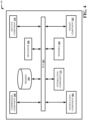
- FIG. 3 illustrates a block diagram of an example, non-limiting system 100 facilitating measuring weight and balance and optimizing center of gravity including a weight component 302 in accordance with one or more embodiments described herein. Repetitive description of like elements employed in other embodiments described herein is omitted for sake of brevity.
- Weight component 302 can calculate the total weight of the aircraft based on the total compression.
- the compression component 108 can calculate the compression for the different landing gear struts.
- Total weight of the aircraft can be calculated by the weight component 302 based on the total compression of all the landing gear struts. More specifically, by using the material property (e.g., Young's modulus) of the landing gear struts, the total weight can be calculated based on the total compression of the landing gear struts.
- Young's modulus Young's modulus
- the sensors 202 can measure the height above ground at multiple locations of the aircraft for determining the total compression.
- the sensors 202 can also measure the change in length of the landing gear struts (e.g., original length and compressed length) for determining (e.g., via the compression component 108) the compression of the landing gear struts and the total compression of all the landing gear struts.
- the weight component 302 can calculate the weight of the aircraft based on the total compression calculated by the compression component 108.
- the weight component 302 can also determine whether the total weight has reached maximum weight capacity.
- the weight component 302 can also determine whether the aircraft is within weight capacity limits and by how much. If the total weight is over the weight capacity limits, a notification can be automatically sent to the flight crew or cabin crew. In addition, a notification can also be automatically sent to the flight crew or cabin crew for out of range center of gravity.
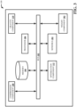
- FIG. 4 illustrates a block diagram of an example, non-limiting system 100 facilitating measuring weight and balance and optimizing center of gravity including a notification component 402 in accordance with one or more embodiments described herein. Repetitive description of like elements employed in other embodiments described herein is omitted for sake of brevity.
- the notification component 402 can automatically notify the flight crew or the cabin crew if the total weight of the aircraft is over the weight capacity limits or if center of gravity is out of range.
- the weight component 302 can calculate total weight of the aircraft and determine whether the aircraft is over weight capacity limits. If the aircraft is over the weight capacity limits, the weight component 302 can send the weight information to notification component 402 to alert the flight crew or the cabin crew.
- the notification component 402 can alert the flight crew or the cabin crew that the aircraft has reached maximum weight capacity limits or that the aircraft is over the weight capacity limits and by how much.
- the notification component 402 can also provide the weight of the aircraft to the flight crew or the cabin crew upon request.
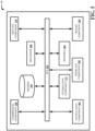
- FIG. 5 illustrates a block diagram of an example, non-limiting system 100 facilitating measuring weight and balance and optimizing center of gravity including a modeling component 502 in accordance with one or more embodiments described herein. Repetitive description of like elements employed in other embodiments described herein is omitted for sake of brevity.
- the modeling component 502 can model flight performance to determine the center of gravity in flight. So, in addition to the gravity component 110 calculating the center of gravity based on the differential compression of the landing gear struts or based on the pitch of the aircraft while on ground, the modeling component can also model the flight performance to determine the center of gravity in flight and whether the center of gravity is optimal (e.g., closest possible to 100% margin within the center of gravity margin).
- the modeling component 502 can model the flight performance of the aircraft based on the pitch, the deflection of the flight control surfaces, the engine settings, fuel use, etc., to determine the expected speed of the aircraft.
- the modeling component 502 can compare the expected speed of the aircraft with the actual speed of the aircraft to determine the center of gravity in flight because speed is affected by the amount of deflection of the flight control surfaces, which is related to the center of gravity.
- the amount of deflection of the flight control surfaces necessary is dependent on the position of the center of gravity.
- the center of gravity can be verified by comparing the expected with actual settings for the flight control surfaces while in flight.
- the modeling component 502 can also compare the actual fuel use with the expected fuel use to determine the center of gravity because more fuel is used with a greater amount of deflection of the flight control surfaces due to increased drag.
- the modeling component 502 can also use other parameters to determine location of center of gravity while in flight.
- the modeling component 502 can use aircraft attitude, airspeed, engine settings, flight control surface deflections, aerodynamic model, etc., to back calculate center of gravity and weight required for the actual settings.
- the modeling component 502 can also access the predicted rate of fuel burn information (e.g., determined by the optimization component 112 by accessing flight plan information), wind conditions and information on how fuel can be continuously pumped (e.g., via the optimization component 112) throughout different tanks to affect center of gravity.
- the modeling component 502 can provide a better estimate on fuel use to fly to a destination as it has a better expectation on fuel burn.
- the modeling component 502 can determine where the center of gravity is in terms of the center of gravity margin.
- the center of gravity can be anywhere on the aircraft, but to be able to fly safely, the center of gravity should be within a certain range called the center of gravity margin that the aircraft is certified to be in. Anything behind the center of gravity margin means the aircraft is unstable. Anything forward of the center of gravity margin, and the aircraft is overly stable that it would require too much control input (e.g., deflection of the flight control surfaces) to control it. If the center of gravity is at 0% of the center of gravity margin, the center of gravity is at the absolute maximum forward that is allowed. If the center of gravity is at 100% of the center of gravity margin, the center of gravity is at the furthest back position allowable.
- the modeling component 502 can begin to analyze the flight control surfaces, flight performance, engine settings, speed, attitude, fuel use, etc., to determine the center of gravity.
- the modeling component 502 can continuously and automatically determine the center of gravity and send that data to the optimization component 112.
- the optimization component 112 can automatically and continuously optimize the center of gravity for fuel efficiency based on the continuous feedback of the center of gravity information from the modeling component 502.
- the optimization component 112 can optimize (e.g., adjust, move, etc.) the center of gravity by pumping fuel between the different fuel tanks.
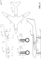
- FIG. 6 illustrates example, non-limiting principle 600 facilitating measuring weight and balance and optimizing center of gravity in accordance with one or more embodiments described herein. Repetitive description of like elements employed in other embodiments described herein is omitted for sake of brevity.
- Image 610 and image 620 depict principle of determining total weight and position of center of gravity.
- Image 610 illustrates an aircraft having center of gravity CG1 equally between landing gear 10 and landing gear 20.
- Force F1 and force F2 illustrate the forces on front landing gear 10 and rear landing gear 20 in image 610, respectively.
- the sum of force F1 and force F2 equals the total weight (e.g., mass) of the aircraft 5.
- Image 620 illustrates center of gravity CG2 is moved towards the front of aircraft 5 making aircraft 5 tilt slightly forward. Force F3 on front landing gear 10 is higher than force F4 on rear landing gear 20. However, the total force of force F3 and force F4 is the same as the total force of force F1 and force F2.
- Image 630 and image 640 illustrate example location of sensors.
- Image 630 illustrates sensor 2 and sensor 3 placed under fuselage 33.
- Sensor 1 and sensor 4 are placed under wing 35 and wing 37, respectively.
- Image 640 illustrates a sideview of aircraft 5 showing sensor 4 measuring height above ground 43.
- Sensor 2 is trained on front landing gear 10, and sensor 3 is trained on rear landing gear 20.
- Sensor 2 and sensor 3 can be cameras or lidar sensors measuring the length of front landing gear 10 and rear landing gear 20, respectively.
- Sensor 1 and sensor 4 can be radar sensors or ultrasound sensors measuring height above ground 43.
- Image 650 and image 660 depict principle of measuring strain and selecting field of measurement.
- Image 650 illustrates sensor 2 capturing the entire length L1 of front landing gear 10 as it tries to measure a small change of length over the entire length L1 of front landing gear 10, e.g., strain.
- Strain can be defined as the change in length divided by the original length (dL/L).
- Material property e.g., Young's modulus
- Young's modulus can be used to calculate the strain for a given stress (e.g., force over a cross-section), which can be used to calculate the force (e.g., mass) resting on front landing gear 10.
- the force resting on rear landing gear 20 can be calculated the same way as well.
- Image 660 illustrates sensor 2 trained at a portion of length L2 of front landing gear 10 to provide a higher resolution to measure strain, and also, to train on a softer material (e.g., higher strain to be measured).
- FIG. 7 illustrates a block diagram of an example, non-limiting computer-implemented method 700 facilitating measuring weight and balance and optimizing center of gravity in accordance with one or more embodiments described herein. Repetitive description of like elements employed in other embodiments described herein is omitted for sake of brevity.
- the computer-implemented method 700 can comprise calculating (e.g., via the compression component 108), by a system operatively coupled to a processor, compression of landing gear struts based on height above ground of an aircraft.
- the computer-implemented method 700 can comprise determining (e.g., via the gravity component 110), by the system, center of gravity based on differential compression of the landing gear struts.
- the computer-implemented method 700 can comprise automatically optimizing (e.g., via the optimization component 112), by the system, the center of gravity to a rear limit of a center of gravity margin.
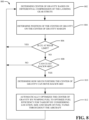
- FIG. 8 illustrates a block diagram of an example, non-limiting computer-implemented method 800 facilitating measuring weight and balance and optimizing center of gravity in accordance with one or more embodiments described herein. Repetitive description of like elements employed in other embodiments described herein is omitted for sake of brevity.
- the gravity component 110 can determine the center of gravity based on differential compression. Differential compression can be calculated (e.g., via the compression component 108) based on measurements (e.g., via the sensors 202) of height above ground at different locations of the aircraft. Differential compression can also be calculated (e.g., via the compression component 108) based on the change in measurements (e.g., via the sensors 202) of the landing gear struts.
- the computer-implemented method 800 can comprise determining (e.g., via the gravity component 110) center of gravity based on differential compression of the landing gear struts.
- the computer-implemented method 800 can comprise determining (e.g., via the gravity component 110) position of the center of gravity on the center of gravity margin.
- the computer-implemented method 800 can comprise determining (e.g., via the gravity component 110) whether the center of gravity is at the rear limit of the center of gravity margin. If yes, the process returns to 802. If no, the process proceeds to 808.
- the computer-implemented method 800 can comprise determining (e.g., via the gravity component 110) whether the center of gravity can go further backward.
- the computer-implemented method 800 can comprise determining (e.g., via the gravity component 110) how much further the center of gravity can move backward.
- the computer-implemented method 800 can comprise automatically optimizing (e.g., via the optimization component 112) the center of gravity by pumping fuel to optimize fuel efficiency for takeoff by considering location, size and shape of fuel tanks throughout the aircraft.
- FIG. 9 illustrates a block diagram of an example, non-limiting computer-implemented method 900 facilitating measuring weight and balance and optimizing center of gravity in accordance with one or more embodiments described herein. Repetitive description of like elements employed in other embodiments described herein is omitted for sake of brevity.
- the modeling component 502 can model the flight performance to determine the center of gravity. Depending on the type of aircraft, the flight performance can be the angle of the deflection of the flight control surfaces, tilt angle of the rotor, engine settings, speed, fuel use, attitude, pitch, etc.
- the computer-implemented method 900 can comprise modeling (e.g., via the modeling component 502) flight performance to determine the center of gravity in flight.
- the computer-implemented method 900 can comprise determining (e.g., via the modeling component 502) position of the center of gravity on the center of gravity margin.
- the computer-implemented method 900 can comprise determining (e.g., via the modeling component 502) whether the center of gravity is at the rear limit of the center of gravity margin. If yes, the process returns to 902. If no, the process proceeds to 908.
- the computer-implemented method 900 can comprise determining (e.g., via the modeling component 502) whether the center of gravity can go further backward. If no, the process returns to 902.
- the computer-implemented method 900 can comprise determining (e.g., via the modeling component 502) how much further the center of gravity can move backward.
- the computer-implemented method 900 can comprise automatically optimizing (e.g., via the optimization component 112) the center of gravity by pumping fuel to optimize fuel efficiency in flight by considering location, size and shape of fuel tanks throughout the aircraft.
- FIG. 10 illustrates a block diagram of an example, non-limiting computer-implemented method 1000 facilitating measuring weight and balance and optimizing center of gravity in accordance with one or more embodiments described herein. Repetitive description of like elements employed in other embodiments described herein is omitted for sake of brevity.
- the computer-implemented method 1000 can comprise calculating (e.g., via the compression component 108) compression of landing gear struts based on height above ground of an aircraft.
- the computer-implemented method 1000 can comprise calculating (e.g., via the weight component 302) total weight of the aircraft based on total compression of the landing gear struts.
- the computer-implemented method 1000 can comprise determining (e.g., via the weight component 302) whether the total weight is over the weight capacity limits. If no, the process returns to 1002. If yes, the process proceeds to 1008. At 1008, the computer-implemented method 1000 can comprise notifying (e.g., via the notification component 402) flight crew or cabin crew the total weight is over the weight capacity limits.
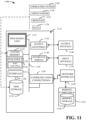
- FIG. 11 illustrates a block diagram of an example, non-limiting operating environment in which one or more embodiments described herein can be facilitated. Repetitive description of like elements employed in other embodiments described herein is omitted for sake of brevity.
- a suitable operating environment 1100 for implementing various aspects of this disclosure can also include a computer 1112.
- the computer 1112 can also include a processing unit 1114, a system memory 1116, and a system bus 1118.
- the system bus 1118 couples system components including, but not limited to, the system memory 1116 to the processing unit 1114.
- the processing unit 1114 can be any of various available processors. Dual microprocessors and other multiprocessor architectures also can be employed as the processing unit 1114.
- the system bus 1118 can be any of several types of bus structure(s) including the memory bus or memory controller, a peripheral bus or external bus, and/or a local bus using any variety of available bus architectures including, but not limited to, Industrial Standard Architecture (ISA), Micro-Channel Architecture (MSA), Extended ISA (EISA), Intelligent Drive Electronics (IDE), VESA Local Bus (VLB), Peripheral Component Interconnect (PCI), Card Bus, Universal Serial Bus (USB), Advanced Graphics Port (AGP), Firewire (IEEE 1394), and Small Computer Systems Interface (SCSI).
- ISA Industrial Standard Architecture
- MSA Micro-Channel Architecture
- EISA Extended ISA
- IDE Intelligent Drive Electronics
- VLB VESA Local Bus
- PCI Peripheral Component Interconnect
- Card Bus Universal Serial Bus
- USB Universal Serial Bus
- AGP Advanced Graphics Port
- Firewire IEEE 1394
- SCSI Small Computer Systems Interface
- the system memory 1116 can also include volatile memory 1120 and nonvolatile memory 1122.
- the basic input/output system (BIOS) containing the basic routines to transfer information between elements within the computer 1112, such as during start-up, is stored in nonvolatile memory 1122.
- Computer 1112 can also include removable/non-removable, volatile/non-volatile computer storage media.
- FIG. 11 illustrates, for example, a disk storage 1124.
- Disk storage 1124 can also include, but is not limited to, devices like a magnetic disk drive, floppy disk drive, tape drive, Jaz drive, Zip drive, LS-100 drive, flash memory card, or memory stick.
- the disk storage 1124 also can include storage media separately or in combination with other storage media.
- FIG. 11 also depicts software that acts as an intermediary between users and the basic computer resources described in the suitable operating environment 1100.
- Such software can also include, for example, an operating system 1128.
- Operating system 1128 which can be stored on disk storage 1124, acts to control and allocate resources of the computer 1112.
- System applications 1130 take advantage of the management of resources by operating system 1128 through program modules 1132 and program data 1134, e.g., stored either in system memory 1116 or on disk storage 1124. It is to be appreciated that this disclosure can be implemented with various operating systems or combinations of operating systems.
- a user enters commands or information into the computer 1112 through input device(s) 1136.
- Input devices 1136 include, but are not limited to, a pointing device such as a mouse, trackball, stylus, touch pad, keyboard, microphone, joystick, game pad, satellite dish, scanner, TV tuner card, digital camera, digital video camera, web camera, and the like. These and other input devices connect to the processing unit 1114 through the system bus 1118 via interface port(s) 1138.
- Interface port(s) 1138 include, for example, a serial port, a parallel port, a game port, and a universal serial bus (USB).
- Output device(s) 1140 use some of the same type of ports as input device(s) 1136.
- a USB port can be used to provide input to computer 1112, and to output information from computer 1112 to an output device 1140.
- Output adapter 1142 is provided to illustrate that there are some output devices 1140 like monitors, speakers, and printers, among other output devices 1140, which require special adapters.
- the output adapters 1142 include, by way of illustration and not limitation, video and sound cards that provide a means of connection between the output device 1140 and the system bus 1118. It should be noted that other devices and/or systems of devices provide both input and output capabilities such as remote computer(s) 1144.
- Computer 1112 can operate in a networked environment using logical connections to one or more remote computers, such as remote computer(s) 1144.
- the remote computer(s) 1144 can be a computer, a server, a router, a network PC, a workstation, a microprocessor based appliance, a peer device or other common network node and the like, and typically can also include many or all of the elements described relative to computer 1112. For purposes of brevity, only a memory storage device 1146 is illustrated with remote computer(s) 1144.
- Remote computer(s) 1144 is logically connected to computer 1112 through a network interface 1148 and then physically connected via communication connection 1150.
- Network interface 1148 encompasses wire and/or wireless communication networks such as local-area networks (LAN), wide-area networks (WAN), cellular networks, etc.
- LAN technologies include Fiber Distributed Data Interface (FDDI), Copper Distributed Data Interface (CDDI), Ethernet, Token Ring and the like.
- WAN technologies include, but are not limited to, point-to-point links, circuit switching networks like Integrated Services Digital Networks (ISDN) and variations thereon, packet switching networks, and Digital Subscriber Lines (DSL).
- Communication connection(s) 1150 refers to the hardware/software employed to connect the network interface 1148 to the system bus 1118. While communication connection 1150 is shown for illustrative clarity inside computer 1112, it can also be external to computer 1112.
- the hardware/software for connection to the network interface 1148 can also include, for exemplary purposes only, internal and external technologies such as, modems including regular telephone grade modems, cable modems and DSL modems, ISDN adapters, and Ethernet cards.
- the present invention may be a system, a method, an apparatus and/or a computer program product at any possible technical detail level of integration
- the computer program product can include a computer readable storage medium (or media) having computer readable program instructions thereon for causing a processor to carry out aspects of the present invention.
- the computer readable storage medium can be a tangible device that can retain and store instructions for use by an instruction execution device.
- the computer readable storage medium can be, for example, but is not limited to, an electronic storage device, a magnetic storage device, an optical storage device, an electromagnetic storage device, a semiconductor storage device, or any suitable combination of the foregoing.
- a non-exhaustive list of more specific examples of the computer readable storage medium can also include the following: a portable computer diskette, a hard disk, a random access memory (RAM), a read-only memory (ROM), an erasable programmable read-only memory (EPROM or Flash memory), a static random access memory (SRAM), a portable compact disc read-only memory (CD-ROM), a digital versatile disk (DVD), a memory stick, a floppy disk, a mechanically encoded device such as punch-cards or raised structures in a groove having instructions recorded thereon, and any suitable combination of the foregoing.
- RAM random access memory
- ROM read-only memory
- EPROM or Flash memory erasable programmable read-only memory
- SRAM static random access memory
- CD-ROM compact disc read-only memory
- DVD digital versatile disk
- memory stick a floppy disk
- a mechanically encoded device such as punch-cards or raised structures in a groove having instructions recorded thereon
- a computer readable storage medium is not to be construed as being transitory signals per se, such as radio waves or other freely propagating electromagnetic waves, electromagnetic waves propagating through a waveguide or other transmission media (e.g., light pulses passing through a fiber-optic cable), or electrical signals transmitted through a wire.
- Computer readable program instructions described herein can be downloaded to respective computing/processing devices from a computer readable storage medium or to an external computer or external storage device via a network, for example, the Internet, a local area network, a wide area network and/or a wireless network.
- the network can comprise copper transmission cables, optical transmission fibers, wireless transmission, routers, firewalls, switches, gateway computers and/or edge servers.
- a network adapter card or network interface in each computing/processing device receives computer readable program instructions from the network and forwards the computer readable program instructions for storage in a computer readable storage medium within the respective computing/processing device.
- Computer readable program instructions for carrying out operations of the present invention can be assembler instructions, instruction-set-architecture (ISA) instructions, machine instructions, machine dependent instructions, microcode, firmware instructions, state-setting data, configuration data for integrated circuitry, or either source code or object code written in any combination of one or more programming languages, including an object oriented programming language such as Smalltalk, C++, or the like, and procedural programming languages, such as the "C" programming language or similar programming languages.
- the computer readable program instructions can execute entirely on the user's computer, partly on the user's computer, as a stand-alone software package, partly on the user's computer and partly on a remote computer or entirely on the remote computer or server.
- the remote computer can be connected to the user's computer through any type of network, including a local area network (LAN) or a wide area network (WAN), or the connection can be made to an external computer (for example, through the Internet using an Internet Service Provider).
- electronic circuitry including, for example, programmable logic circuitry, field-programmable gate arrays (FPGA), or programmable logic arrays (PLA) can execute the computer readable program instructions by utilizing state information of the computer readable program instructions to personalize the electronic circuitry, in order to perform aspects of the present invention.
- These computer readable program instructions can also be stored in a computer readable storage medium that can direct a computer, a programmable data processing apparatus, and/or other devices to function in a particular manner, such that the computer readable storage medium having instructions stored therein comprises an article of manufacture including instructions which implement aspects of the function/act specified in the flowchart and/or block diagram block or blocks.
- the computer readable program instructions can also be loaded onto a computer, other programmable data processing apparatus, or other device to cause a series of operational acts to be performed on the computer, other programmable apparatus or other device to produce a computer implemented process, such that the instructions which execute on the computer, other programmable apparatus, or other device implement the functions/acts specified in the flowchart and/or block diagram block or blocks.
- each block in the flowchart or block diagrams can represent a module, segment, or portion of instructions, which comprises one or more executable instructions for implementing the specified logical function(s).
- the functions noted in the blocks can occur out of the order noted in the Figures.
- two blocks shown in succession can, in fact, be executed substantially concurrently, or the blocks can sometimes be executed in the reverse order, depending upon the functionality involved.
- program modules include routines, programs, components, data structures, etc., that perform particular tasks and/or implement particular abstract data types.
- inventive computer-implemented methods can be practiced with other computer system configurations, including single-processor or multiprocessor computer systems, mini-computing devices, mainframe computers, as well as computers, hand-held computing devices (e.g., PDA, phone), microprocessor-based or programmable consumer or industrial electronics, and the like.
- the illustrated aspects can also be practiced in distributed computing environments in which tasks are performed by remote processing devices that are linked through a communications network. However, some, if not all aspects of this disclosure can be practiced on stand-alone computers. In a distributed computing environment, program modules can be located in both local and remote memory storage devices.
- ком ⁇ онент can refer to and/or can include a computer-related entity or an entity related to an operational machine with one or more specific functionalities.
- the entities disclosed herein can be either hardware, a combination of hardware and software, software, or software in execution.
- a component can be, but is not limited to being, a process running on a processor, a processor, an object, an executable, a thread of execution, a program, and/or a computer.
- an application running on a server and the server can be a component.
- One or more components can reside within a process and/or thread of execution and a component can be localized on one computer and/or distributed between two or more computers.
- respective components can execute from various computer readable media having various data structures stored thereon.
- the components can communicate via local and/or remote processes such as in accordance with a signal having one or more data packets (e.g., data from one component interacting with another component in a local system, distributed system, and/or across a network such as the Internet with other systems via the signal).
- a component can be an apparatus with specific functionality provided by mechanical parts operated by electric or electronic circuitry, which is operated by a software or firmware application executed by a processor.
- a component can be an apparatus that provides specific functionality through electronic components without mechanical parts, wherein the electronic components can include a processor or other means to execute software or firmware that confers at least in part the functionality of the electronic components.
- a component can emulate an electronic component via a virtual machine, e.g., within a cloud computing system.
- processor can refer to substantially any computing processing unit or device comprising, but not limited to, single-core processors; single-processors with software multithread execution capability; multi-core processors; multi-core processors with software multithread execution capability; multi-core processors with hardware multithread technology; parallel platforms; and parallel platforms with distributed shared memory.
- a processor can refer to an integrated circuit, an application specific integrated circuit (ASIC), a digital signal processor (DSP), a field programmable gate array (FPGA), a programmable logic controller (PLC), a complex programmable logic device (CPLD), a discrete gate or transistor logic, discrete hardware components, or any combination thereof designed to perform the functions described herein.
- ASIC application specific integrated circuit
- DSP digital signal processor
- FPGA field programmable gate array
- PLC programmable logic controller
- CPLD complex programmable logic device
- processors can exploit nano-scale architectures such as, but not limited to, molecular and quantum-dot based transistors, switches and gates, in order to optimize space usage or enhance performance of user equipment.
- a processor can also be implemented as a combination of computing processing units.
- terms such as “store,” “storage,” “data store,” data storage,” “database,” and substantially any other information storage component relevant to operation and functionality of a component are utilized to refer to "memory components," entities embodied in a "memory,” or components comprising a memory. It is to be appreciated that memory and/or memory components described herein can be either volatile memory or nonvolatile memory, or can include both volatile and nonvolatile memory.
- nonvolatile memory can include read only memory (ROM), programmable ROM (PROM), electrically programmable ROM (EPROM), electrically erasable ROM (EEPROM), flash memory, or nonvolatile random access memory (RAM) (e.g., ferroelectric RAM (FeRAM).
- Volatile memory can include RAM, which can act as external cache memory, for example.
- RAM is available in many forms such as synchronous RAM (SRAM), dynamic RAM (DRAM), synchronous DRAM (SDRAM), double data rate SDRAM (DDR SDRAM), enhanced SDRAM (ESDRAM), Synchlink DRAM (SLDRAM), direct Rambus RAM (DRRAM), direct Rambus dynamic RAM (DRDRAM), and Rambus dynamic RAM (RDRAM).
- SRAM synchronous RAM
- DRAM dynamic RAM
- SDRAM synchronous DRAM
- DDR SDRAM double data rate SDRAM
- ESDRAM enhanced SDRAM
- SLDRAM Synchlink DRAM
- DRRAM direct Rambus RAM
- DRAM direct Rambus dynamic RAM
- RDRAM Rambus dynamic RAM
Landscapes
- Engineering & Computer Science (AREA)
- Aviation & Aerospace Engineering (AREA)
- Physics & Mathematics (AREA)
- General Physics & Mathematics (AREA)
- Chemical & Material Sciences (AREA)
- Combustion & Propulsion (AREA)
- Mechanical Engineering (AREA)
- Fluid Mechanics (AREA)
- General Engineering & Computer Science (AREA)
- Testing Of Balance (AREA)
Claims (10)
- Procédé implémenté par ordinateur comprenant :la détermination d'un centre de gravité d'un aéronef pendant le vol en fonction d'une modélisation (902) de performance de vol de l'aéronef ;la détermination (904) d'une position du centre de gravité par comparaison avec une marge de centre de gravité de l'aéronef ; etl'optimisation automatique (912) de la position du centre de gravité par transfert de carburant entre des réservoirs de carburant et pour optimiser le rendement de carburant en vol en considérant la localisation, la taille et la forme des réservoirs de carburant sur l'ensemble de l'aéronef, l'optimisation automatique étant en fonction de la détermination de la position du centre de gravité par comparaison avec la marge de centre de gravité, et l'optimisation automatique utilisant en outre des informations de plan de vol pour prédire la performance d'aéronef et pour prévoir un transfert de carburant selon la performance prédite d'aéronef.
- Procédé implémenté par ordinateur selon la revendication 1, comprenant en outre le fait de déterminer (906) si le centre de gravité est au niveau d'une limite arrière de la marge de centre de gravité.
- Procédé implémenté par ordinateur selon la revendication 2, comprenant en outre, en réponse à la détermination que le centre de gravité n'est pas au niveau de la limite arrière de la marge de centre de gravité, le fait de déterminer (908) si le centre de gravité peut aller davantage vers l'arrière en direction d'une position arrière de l'aéronef.
- Procédé implémenté par ordinateur selon la revendication 3, comprenant en outre, en réponse à la détermination que le centre de gravité peut aller davantage vers l'arrière, la détermination (910) de la valeur selon laquelle le centre de gravité peut se déplacer davantage vers l'arrière en direction de la position arrière de l'aéronef.
- Procédé implémenté par ordinateur selon l'une quelconque revendication précédente dans lequel la performance de vol est une fonction d'un ou plusieurs parmi : angle de déflexion de gouvernes de vol, angle d'inclinaison d'un rotor, réglages de moteur, vitesse, utilisation de carburant, attitude, et tangage.
- Système comprenant :une mémoire (104) qui stocke des composants exécutables par ordinateur ;un processeur (106), accouplé fonctionnellement à la mémoire (104), qui exécute les composants exécutables par ordinateur stockés dans la mémoire (104), les composants exécutables par ordinateur comprenant :
un composant de modélisation (502) configuré pour :déterminer un centre de gravité d'un aéronef pendant le vol par modélisation (902) de performance de vol de l'aéronef ; etdéterminer (904) une position du centre de gravité par rapport à une marge de centre de gravité de l'aéronef ; etun composant d'optimisation (112) configuré pour optimiser automatiquement (912) la position du centre de gravité par pompage de carburant entre des réservoirs de carburant pour optimiser le rendement de carburant pendant le vol en considérant la localisation, la taille et la forme des réservoirs de carburant sur l'ensemble de l'aéronef, le composant d'optimisation (112) étant configuré en outre pour utiliser des informations de plan de vol pour prédire une performance d'aéronef et pour prévoir un transfert de carburant selon la performance prédite d'aéronef. - Système selon la revendication 6, dans lequel le composant de modélisation (502) est configuré pour déterminer de façon continue et automatique le centre de gravité, résultant en des informations de centre de gravité déterminé, et envoyer les informations de centre de gravité déterminé au composant d'optimisation (112).
- Système selon les revendications 6 ou 7, dans lequel le composant d'optimisation (112) est configuré pour optimiser de façon continue et automatique le centre de gravité pour le rendement de carburant en fonction d'une rétroaction continue des informations de centre de gravité déterminé à partir du composant de modélisation (502).
- Système selon l'une quelconque des revendications 6 à 8, dans lequel le composant de modélisation (502) est configuré pour modéliser la performance de vol de l'aéronef en fonction d'un ou plusieurs paramètres choisis dans un groupe de paramètres constitués par : angle de déflexion de gouvernes de vol, angle d'inclinaison d'un rotor, réglages de moteur, vitesse, utilisation de carburant, attitude, et tangage.
- Système selon l'une quelconque des revendications 6 à 9, dans lequel le composant de modélisation (502) est configuré pour accéder à des informations de taux prédit de consommation de carburant, à des conditions de vent, et/ou à des informations concernant la manière dont le carburant peut être pompé de façon continue par le composant d'optimisation (112) sur l'ensemble des différents réservoirs pour influer sur le centre de gravité.
Applications Claiming Priority (2)
| Application Number | Priority Date | Filing Date | Title |
|---|---|---|---|
| GB1814286.9A GB2576787B (en) | 2018-09-03 | 2018-09-03 | Measuring weight and balance and optimizing center of gravity |
| EP19194393.5A EP3620769B1 (fr) | 2018-09-03 | 2019-08-29 | Mesure du poids et de l'équilibre et optimisation du centre de gravité |
Related Parent Applications (2)
| Application Number | Title | Priority Date | Filing Date |
|---|---|---|---|
| EP19194393.5A Division EP3620769B1 (fr) | 2018-09-03 | 2019-08-29 | Mesure du poids et de l'équilibre et optimisation du centre de gravité |
| EP19194393.5A Division-Into EP3620769B1 (fr) | 2018-09-03 | 2019-08-29 | Mesure du poids et de l'équilibre et optimisation du centre de gravité |
Publications (2)
| Publication Number | Publication Date |
|---|---|
| EP3929552A1 EP3929552A1 (fr) | 2021-12-29 |
| EP3929552B1 true EP3929552B1 (fr) | 2023-11-15 |
Family
ID=63920924
Family Applications (2)
| Application Number | Title | Priority Date | Filing Date |
|---|---|---|---|
| EP19194393.5A Active EP3620769B1 (fr) | 2018-09-03 | 2019-08-29 | Mesure du poids et de l'équilibre et optimisation du centre de gravité |
| EP21167730.7A Active EP3929552B1 (fr) | 2018-09-03 | 2019-08-29 | Mesure du poids et de l'équilibre et optimisation du centre de gravité |
Family Applications Before (1)
| Application Number | Title | Priority Date | Filing Date |
|---|---|---|---|
| EP19194393.5A Active EP3620769B1 (fr) | 2018-09-03 | 2019-08-29 | Mesure du poids et de l'équilibre et optimisation du centre de gravité |
Country Status (4)
| Country | Link |
|---|---|
| US (2) | US11377203B2 (fr) |
| EP (2) | EP3620769B1 (fr) |
| CN (1) | CN110874499A (fr) |
| GB (1) | GB2576787B (fr) |
Families Citing this family (27)
| Publication number | Priority date | Publication date | Assignee | Title |
|---|---|---|---|---|
| US12293376B2 (en) * | 2015-10-27 | 2025-05-06 | C Kirk Nance | Method for determining data to be transmitted off-aircraft for processing of aircraft weight and center of gravity information |
| US12017798B2 (en) * | 2016-06-10 | 2024-06-25 | Metal Raptor Inc. | Drone load optimization using the center of gravity of multiple objects |
| US12358644B2 (en) * | 2016-06-10 | 2025-07-15 | Metal Raptor Inc. | Drone package loading based on package characterization |
| IL261364B (en) * | 2018-08-24 | 2021-08-31 | Levy Moshe | Automatic adjustment system for changing the center of gravity in a powered parachute |
| GB2576787B (en) | 2018-09-03 | 2022-05-11 | Ge Aviat Systems Ltd | Measuring weight and balance and optimizing center of gravity |
| JP7269033B2 (ja) * | 2019-03-01 | 2023-05-08 | 株式会社Subaru | 回転翼航空機 |
| FR3108314B1 (fr) * | 2020-03-23 | 2022-04-08 | Airbus | Système et procédé destinés à estimer une bonne répartition de chargement à bord d’un aéronef. |
| CN111942577B (zh) * | 2020-08-13 | 2022-01-07 | 北京京东乾石科技有限公司 | 一种无人机的重心配平方法及无人机 |
| CN112560250B (zh) * | 2020-12-10 | 2024-04-09 | 中国航空工业集团公司沈阳飞机设计研究所 | 一种飞机内埋悬挂物自动占位控制方法 |
| BR112023015265A2 (pt) | 2021-01-28 | 2023-11-07 | Scoutcam Ltd | Sistema para monitorar falhas em potencial em uma máquina ou um componente da mesma e método implementado por computador para monitorar uma máquina ou um componente da mesma |
| US12084196B2 (en) * | 2021-08-17 | 2024-09-10 | Textron Innovations Inc. | Estimating available power for an aircraft battery |
| CN113868834A (zh) * | 2021-08-31 | 2021-12-31 | 航天时代飞鹏有限公司 | 一种后三点式无人运输机地面滑行纠偏控制方法及装置 |
| GB2611096A (en) * | 2021-09-28 | 2023-03-29 | Airbus Operations Ltd | Determining the position of one or more components of a landing gear assembly of an aircraft |
| GB2612297A (en) | 2021-09-28 | 2023-05-03 | Airbus Operations Ltd | Determining the steering angle of a landing gear assembly of an aircraft |
| RU2767969C1 (ru) * | 2021-10-25 | 2022-03-22 | Руслан Валерьевич Новоселов | Способ определения координат центра масс беспилотного вертолета |
| WO2023091788A1 (fr) | 2021-11-22 | 2023-05-25 | Nance C Kirk | Procédé et système pour augmenter la précision des déterminations du poids d'un aéronef et du centre de gravité associé |
| CN114414146B (zh) * | 2021-12-17 | 2023-04-18 | 北京航空航天大学 | 一种飞行安全判定方法、系统、存储介质及电子设备 |
| GB2616077A (en) * | 2022-02-28 | 2023-08-30 | Airbus Operations Ltd | Aircraft steering angle determination |
| GB2617315A (en) | 2022-03-28 | 2023-10-11 | Airbus Operations Ltd | Determining a load condition of an aircraft |
| IL316571A (en) * | 2022-04-27 | 2024-12-01 | Odysight Ai Ltd | Monitoring a mechanism or component of a mechanism |
| CN115857851B (zh) * | 2022-11-21 | 2024-05-14 | 中国民航信息网络股份有限公司 | 一种航班配载重心显示方法及装置 |
| CN115806056A (zh) * | 2022-11-25 | 2023-03-17 | 重庆绿航佳航空科技有限公司 | 一种直升机重量平衡的适航认证方法 |
| JP2024105975A (ja) * | 2023-01-26 | 2024-08-07 | 株式会社日立製作所 | 電力変換システムおよび飛行体 |
| DE102023119550A1 (de) * | 2023-07-25 | 2025-01-30 | Lufthansa Technik Aktiengesellschaft | Verfahren zur Reduktion des Treibstoffverbrauchs von Flugzeugen und Flugzeug |
| US12473078B2 (en) * | 2023-09-08 | 2025-11-18 | Anduril Industries, Inc. | Fuel measurement for vertical take-off dual-engine aircraft |
| CN119714683A (zh) * | 2024-12-17 | 2025-03-28 | 中国航空工业集团公司西安飞机设计研究所 | 超音速飞机重心范围确定方法、系统及电子设备、介质 |
| CN119773960B (zh) * | 2025-02-28 | 2025-12-09 | 中国商用飞机有限责任公司 | 一种基于液位和流量的水配重系统控制方法 |
Family Cites Families (105)
| Publication number | Priority date | Publication date | Assignee | Title |
|---|---|---|---|---|
| GB505109A (en) * | 1937-11-04 | 1939-05-04 | Gen Aircraft Ltd | Improvements relating to landing gear arrangements of aircraft |
| GB647642A (en) * | 1940-02-23 | 1950-12-20 | Albert Saporta | Landing gear enabling an aircraft to land on and take off from unprepared ground |
| US2443045A (en) * | 1944-03-09 | 1948-06-08 | Glenn L Martin Co | Strain gauge center of gravity and gross weight meter |
| US3426586A (en) * | 1966-06-17 | 1969-02-11 | Blh Electronics | Aircraft weight measurements |
| US4110605A (en) * | 1977-02-25 | 1978-08-29 | Sperry Rand Corporation | Weight and balance computer apparatus for aircraft |
| US4622639A (en) * | 1983-12-16 | 1986-11-11 | The Boeing Company | Aircraft center of gravity and fuel level advisory system |
| US5327347A (en) * | 1984-04-27 | 1994-07-05 | Hagenbuch Roy George Le | Apparatus and method responsive to the on-board measuring of haulage parameters of a vehicle |
| FR2609545B1 (fr) * | 1987-01-08 | 1991-01-04 | Aerospatiale | Procede et systeme pour la determination de la position longitudinale du centre de gravite d'un aeronef pourvu d'un empennage horizontal reglable et application a la surveillance dudit centre de gravite au voisinage du foyer de l'aeronef |
| FR2609546B1 (fr) * | 1987-01-08 | 1991-01-04 | Aerospatiale | Procede et systeme pour la determination de la position longitudinale du centre de gravite d'un aeronef pourvu d'un empennage horizontal reglable |
| US5321945A (en) * | 1990-04-02 | 1994-06-21 | Honeywell Inc. | Apparatus for controlling fuel transfers in a distributed fuel tank system |
| DE4112674A1 (de) * | 1990-09-13 | 1992-03-19 | Vdo Schindling | Anordnung von sensoren an dem fahrwerk eines flugkoerpers zur messung von gewicht und schwerpunktlage des flugkoerpers |
| DE69312687T2 (de) * | 1992-02-07 | 1998-02-26 | C. Kirk Arlington Tex. Nance | Anzeiger von gewicht und schwerpunkt von flugzeugen |
| US5214586A (en) * | 1992-02-07 | 1993-05-25 | Nance C Kirk | Aircraft weight and center of gravity indicator |
| US5521827A (en) * | 1994-09-16 | 1996-05-28 | General Electrodynamics Corporation | On-board aircraft weighting and center of gravity determing apparatus and method |
| KR100231757B1 (ko) * | 1996-02-21 | 1999-11-15 | 사쿠마 하지메 | 건설기계의 작업기 제어방법 및 그 장치 |
| US6128951A (en) * | 1997-04-15 | 2000-10-10 | Trinity Airweighs, L.L.C. | Aircraft weight and center of gravity indicator |
| US6032090A (en) * | 1997-05-06 | 2000-02-29 | General Electrodynamics Corporation | System and method for on-board determination of aircraft weight and load-related characteristics |
| US5784945A (en) * | 1997-05-14 | 1998-07-28 | Caterpillar Inc. | Method and apparatus for determining a valve transform |
| US6353793B1 (en) * | 1999-02-01 | 2002-03-05 | Aero Modifications & Consulting, Llc | System and apparatus for determining the center of gravity of an aircraft |
| US6308131B1 (en) * | 2000-05-25 | 2001-10-23 | Capital Cargo International Airlines, Inc. | Method of pre-planning the loading of aircraft |
| US6600991B1 (en) * | 2001-08-14 | 2003-07-29 | The United States Of America As Represented By The Administrator Of The National Aeronautics And Space Administration | Neighboring optimal aircraft guidance in a general wind environment |
| US6918244B2 (en) * | 2001-08-17 | 2005-07-19 | John Eugene Dickau | Vertical takeoff and landing aircraft propulsion systems |
| CN1284211C (zh) | 2002-12-03 | 2006-11-08 | 旺宏电子股份有限公司 | 利用研磨垫整理装置整理研磨垫的方法 |
| US6913228B2 (en) * | 2003-09-04 | 2005-07-05 | Supersonic Aerospace International, Llc | Aircraft with active center of gravity control |
| US7894961B2 (en) * | 2004-11-12 | 2011-02-22 | Caterpillar Inc | Dump cycle counting and monitoring system |
| US7193530B2 (en) * | 2005-03-29 | 2007-03-20 | Nance C Kirk | Aircraft landing gear automated inspection and life limitation escalation system and method |
| US7274309B2 (en) * | 2005-03-29 | 2007-09-25 | Nance C Kirk | Aircraft landing gear initial touch-down velocity monitor |
| US7274310B1 (en) * | 2005-03-29 | 2007-09-25 | Nance C Kirk | Aircraft landing gear kinetic energy monitor |
| US20060220918A1 (en) * | 2005-03-30 | 2006-10-05 | Daniel Stockwell | Rotating seal for anti-stiction of hydraulic struts |
| FR2883967B1 (fr) * | 2005-04-04 | 2007-06-29 | Messier Bugatti Sa | Dispositif et procede de determination du poids et/ou d'une grandeur caracteristique du centrage d'un aeronef |
| US7281418B2 (en) * | 2005-07-12 | 2007-10-16 | Technology Patents, Llc | System and method of measuring weight of passengers and luggage, and weight distribution of aircraft |
| US7967244B2 (en) * | 2006-11-16 | 2011-06-28 | The Boeing Company | Onboard aircraft weight and balance system |
| US20080147366A1 (en) * | 2006-12-19 | 2008-06-19 | Science Application International Corporation | System and method for displaying simulation data and visualization data |
| US7890249B2 (en) * | 2007-07-06 | 2011-02-15 | Nordic Industries, Inc. | System and method for determining a center of gravity of an aircraft |
| US8042765B1 (en) * | 2008-05-20 | 2011-10-25 | Nance C Kirk | Aircraft landing gear compression rate monitor |
| US8226040B2 (en) * | 2008-08-25 | 2012-07-24 | Embraer S.A. | Continuous fuel management system for automatic control of aircraft center of gravity |
| US8060296B2 (en) * | 2008-11-12 | 2011-11-15 | Honeywell International Inc. | Low cost aircraft center of gravity monitoring systems and methods |
| BRPI0823213A2 (pt) * | 2008-11-25 | 2015-06-30 | Airbus Operations Ltd | Método de controle do código de uma aeronave. |
| US8180504B1 (en) * | 2009-05-21 | 2012-05-15 | Nance C Kirk | Aircraft landing gear compression rate monitor and method to increase aircraft landing weight limitation |
| CN102460324B (zh) * | 2009-05-25 | 2014-07-30 | 维斯塔斯风力系统集团公司 | 一个全局精确时间和一个最大传输时间 |
| US8437920B2 (en) * | 2010-06-04 | 2013-05-07 | Caterpillar Global Mining Llc | Dual monitor information display system and method for an excavator |
| US9205913B2 (en) * | 2010-09-09 | 2015-12-08 | Groen Brothers Aviation, Inc. | Rotorcraft, dynamic, CG management apparatus and method |
| US8548668B2 (en) * | 2010-11-30 | 2013-10-01 | Caterpillar Inc. | Control system having tool tracking |
| US8655505B2 (en) * | 2011-02-18 | 2014-02-18 | Caterpillar Inc. | Worksite management system implementing remote machine reconfiguration |
| US8543322B1 (en) * | 2011-03-14 | 2013-09-24 | C. Kirk Nance | Methods for determination of optimum sequence for automated activation of onboard aircraft weight and balance system |
| US8818696B2 (en) * | 2011-03-23 | 2014-08-26 | Ge Aviation Systems Llc | Method and system for aerial vehicle trajectory management |
| US8565965B2 (en) * | 2011-04-01 | 2013-10-22 | C. Kirk Nance | Aircraft landing gear automated inspection for presence of internal oxygen contamination |
| US10237688B2 (en) * | 2011-08-18 | 2019-03-19 | Rivada Research, Llc | Method and system for improving the location of fixed wireless CBSD nodes |
| US9485623B2 (en) * | 2011-08-18 | 2016-11-01 | Rivada Research, Llc | Method and system for providing enhanced location based trilateration |
| US8774752B1 (en) * | 2011-12-14 | 2014-07-08 | Lonestar Inventions, L.P. | Method for emergency alert using SMS text |
| DE102011056777B4 (de) * | 2011-12-21 | 2013-11-28 | Deutsches Zentrum für Luft- und Raumfahrt e.V. | Schwerpunktermittlung |
| US9161166B2 (en) * | 2012-02-24 | 2015-10-13 | Blackberry Limited | Method and apparatus for interconnected devices |
| WO2013140679A1 (fr) * | 2012-03-21 | 2013-09-26 | 三菱電機株式会社 | Dispositif de régulation de suivi de piste |
| US10384796B2 (en) | 2012-04-04 | 2019-08-20 | Commercial Aerospace Plane Pty Limited | Aerospace plane system |
| US8839675B2 (en) * | 2012-04-17 | 2014-09-23 | The Boeing Company | System and method for ground vibration testing and weight and balance measurement |
| US8954243B2 (en) * | 2013-05-09 | 2015-02-10 | Caterpillar Inc. | Dynamic tip-off detection, display and location selection |
| US8963353B1 (en) * | 2013-09-19 | 2015-02-24 | General Electric Company | System and method to minimize grid spinning reserve losses by pre-emptively sequencing power generation equipment to offset wind generation capacity based on geospatial regional wind conditions |
| US9927319B2 (en) * | 2013-10-01 | 2018-03-27 | C. Kirk Nance | Method for determining aircraft center of gravity independent of measuring the aircraft weight |
| US20180216988A1 (en) * | 2013-10-01 | 2018-08-02 | C. Kirk Nance | Method and apparatus for monitoring and avoidance of unanticipated loads applied to aircraft landing gear |
| US20150100227A1 (en) * | 2013-10-09 | 2015-04-09 | C. Kirk Nance | Method for expanding aircraft center of gravity limitations |
| WO2015175440A1 (fr) * | 2014-05-12 | 2015-11-19 | Unmanned Innovation, Inc. | Autorisation de véhicule aérien sans pilote et détermination d'enveloppe de géorepérage |
| US10380900B2 (en) * | 2014-05-20 | 2019-08-13 | Verizon Patent And Licensing Inc. | Information collection and component/software upgrades for unmanned aerial vehicles |
| US9354296B2 (en) * | 2014-05-20 | 2016-05-31 | Verizon Patent And Licensing Inc. | Dynamic selection of unmanned aerial vehicles |
| US9916505B2 (en) * | 2014-09-22 | 2018-03-13 | Deere & Company | Method and system for collecting image data |
| US20160140851A1 (en) * | 2014-11-18 | 2016-05-19 | Ziv LEVY | Systems and methods for drone navigation |
| US9489852B1 (en) * | 2015-01-22 | 2016-11-08 | Zipline International Inc. | Unmanned aerial vehicle management system |
| CN113031652A (zh) * | 2015-03-31 | 2021-06-25 | 深圳市大疆创新科技有限公司 | 针对限飞区域的开放平台 |
| US9989511B2 (en) * | 2015-04-10 | 2018-06-05 | Caterpillar Inc. | Automated material tagging system |
| US10023323B1 (en) * | 2015-04-29 | 2018-07-17 | X Development Llc | Estimating wind from an airborne vehicle |
| EP3861844B1 (fr) * | 2015-06-08 | 2023-08-30 | Climate LLC | Analyse de données agricoles |
| US9953540B2 (en) * | 2015-06-16 | 2018-04-24 | Here Global B.V. | Air space maps |
| US10518872B2 (en) * | 2015-06-25 | 2019-12-31 | Simmonds Precision Products, Inc. | Continuous fuel tank level control |
| US10867277B2 (en) * | 2015-07-08 | 2020-12-15 | Ebay Inc. | Public transport infrastructure facilitated drone delivery |
| US9928649B2 (en) * | 2015-08-03 | 2018-03-27 | Amber Garage, Inc. | Interface for planning flight path |
| US10269257B1 (en) * | 2015-08-11 | 2019-04-23 | Gopro, Inc. | Systems and methods for vehicle guidance |
| WO2017044079A1 (fr) * | 2015-09-09 | 2017-03-16 | Thomson Licensing | Procédé et appareil pour l'attribution d'un espace aérien pour des véhicules aériens sans pilote |
| US11416871B2 (en) * | 2015-10-27 | 2022-08-16 | C Kirk Nance | Method for determining data to be transmitted off aircraft for processing of aircraft weight and center of gravity information |
| US9994307B2 (en) * | 2016-03-25 | 2018-06-12 | The United States Of America As Represented By Secretary Of The Navy | Vertical take-off-and-landing unmanned aerial vehicle system capable of landing on uneven or sloped terrain |
| US20170316510A1 (en) * | 2016-04-14 | 2017-11-02 | Verifly Technology, Limited | System and method for analyzing drone flight risk |
| US20190145794A1 (en) * | 2016-04-21 | 2019-05-16 | Winning Algorithms Inc. | System and Method for Predicting Hyper-Local Conditions and Optimizing Navigation Performance |
| US11597614B2 (en) * | 2016-06-10 | 2023-03-07 | Metal Raptor, Llc | Center of gravity based drone loading for multiple items |
| US10036137B2 (en) * | 2016-07-15 | 2018-07-31 | Caterpillar Inc. | Autonomous loading system and method for operating same |
| CN107782481B (zh) * | 2016-08-30 | 2020-08-11 | 中国飞行试验研究院 | 一种双轮支柱式前起落架扭力臂载荷的地面校准方法 |
| WO2018049290A1 (fr) * | 2016-09-09 | 2018-03-15 | Cibo Technologies, Inc. | Systèmes destinés à déterminer des sorties agronomiques d'une région cultivable, et appareil et procédés associés |
| US10479481B2 (en) * | 2016-09-28 | 2019-11-19 | The Boeing Company | Process and machine for reducing a drag component of a horizontal stabilizer on an aircraft |
| US10234368B2 (en) * | 2016-10-13 | 2019-03-19 | Deere & Company | System and method for load evaluation |
| US9805595B1 (en) * | 2016-10-27 | 2017-10-31 | International Business Machines Corporation | Vehicle and non-vehicle traffic flow control |
| US10832351B2 (en) * | 2016-11-01 | 2020-11-10 | Deere & Company | Correcting bias in agricultural parameter monitoring |
| US10408645B2 (en) * | 2016-11-01 | 2019-09-10 | Deere & Company | Correcting bias in parameter monitoring |
| US10398096B2 (en) * | 2016-11-16 | 2019-09-03 | The Climate Corporation | Identifying management zones in agricultural fields and generating planting plans for the zones |
| KR20180056068A (ko) * | 2016-11-18 | 2018-05-28 | 삼성전자주식회사 | 무인 비행체를 제어하기 위한 전자 장치 및 방법 |
| WO2018175349A1 (fr) * | 2017-03-19 | 2018-09-27 | Zunum Aero, Inc. | Aéronef hybride-électrique, et procédés, appareil et systèmes destinés à faciliter ledit aéronef |
| US10669015B2 (en) * | 2017-06-07 | 2020-06-02 | The Boeing Company | Automatic adjustment of center of mass of a vehicle |
| CN107506533B (zh) * | 2017-08-03 | 2020-09-18 | 中国航空工业集团公司西安飞机设计研究所 | 一种准静态起落架动力学模型构建方法 |
| US10425831B2 (en) * | 2017-08-29 | 2019-09-24 | T-Mobile Usa, Inc. | Improving coverage in a cellular network using temporary subscriber indentifiers |
| CA3076391A1 (fr) * | 2017-09-29 | 2019-04-04 | Bombardier Inc. | Procede, systeme et indicateur graphique permettant la fourniture d'un centre de gravite lateral d'un aeronef |
| US10859431B2 (en) * | 2017-12-14 | 2020-12-08 | C. Kirk Nance | Method for determining, predicting and correcting breakout friction errors influencing aircraft telescopic landing gear strut pressures |
| EP3514511B1 (fr) * | 2018-01-17 | 2021-03-17 | Airbus Defence and Space, S.A.U. | Procédé et système permettant de déterminer le poids et le centre de gravité d'une structure |
| US20190291883A1 (en) * | 2018-03-20 | 2019-09-26 | Hoversurf, Inc. | Flying vehicle emergency procedures |
| US11042150B2 (en) * | 2018-04-17 | 2021-06-22 | Massachusetts Institute Of Technology | Aircraft fuel efficiency tunnel display for pilots and dispatchers |
| GB2576787B (en) | 2018-09-03 | 2022-05-11 | Ge Aviat Systems Ltd | Measuring weight and balance and optimizing center of gravity |
| US20200166401A1 (en) * | 2018-11-23 | 2020-05-28 | Troy Robert Reabe | Method And System For Weighing Payload In A Flying Aircraft |
| US10890907B2 (en) * | 2018-12-14 | 2021-01-12 | Toyota Jidosha Kabushiki Kaisha | Vehicle component modification based on vehicular accident reconstruction data |
| US11494921B2 (en) * | 2019-04-26 | 2022-11-08 | Samsara Networks Inc. | Machine-learned model based event detection |
| US11080568B2 (en) * | 2019-04-26 | 2021-08-03 | Samsara Inc. | Object-model based event detection system |
-
2018
- 2018-09-03 GB GB1814286.9A patent/GB2576787B/en active Active
-
2019
- 2019-08-13 US US16/539,424 patent/US11377203B2/en active Active
- 2019-08-29 EP EP19194393.5A patent/EP3620769B1/fr active Active
- 2019-08-29 EP EP21167730.7A patent/EP3929552B1/fr active Active
- 2019-09-02 CN CN201910823095.XA patent/CN110874499A/zh active Pending
-
2022
- 2022-06-06 US US17/833,067 patent/US11685518B2/en active Active
Also Published As
| Publication number | Publication date |
|---|---|
| EP3620769A1 (fr) | 2020-03-11 |
| US20220306286A1 (en) | 2022-09-29 |
| GB2576787A8 (en) | 2020-10-21 |
| US11377203B2 (en) | 2022-07-05 |
| EP3929552A1 (fr) | 2021-12-29 |
| US11685518B2 (en) | 2023-06-27 |
| GB2576787B (en) | 2022-05-11 |
| GB2576787A (en) | 2020-03-04 |
| GB201814286D0 (en) | 2018-10-17 |
| CN110874499A (zh) | 2020-03-10 |
| US20200070960A1 (en) | 2020-03-05 |
| EP3620769B1 (fr) | 2021-05-19 |
Similar Documents
| Publication | Publication Date | Title |
|---|---|---|
| US11685518B2 (en) | Measuring weight and balance and optimizing center of gravity | |
| Zhu et al. | Design and assessment of octocopter drones with improved aerodynamic efficiency and performance | |
| US12586478B2 (en) | Unsupervised anomaly detection for autonomous vehicles | |
| US11592791B1 (en) | Systems and methods for flight control system using simulator data | |
| Gryte et al. | Aerodynamic modeling of the skywalker x8 fixed-wing unmanned aerial vehicle | |
| US8653990B2 (en) | Stall management system | |
| US11803197B2 (en) | Systems and methods for controlling a flight boundary of an aircraft | |
| US11988742B2 (en) | Detect and avoid system and method for aerial vehicles | |
| RU2764046C2 (ru) | Балансировка самолета при взлете с использованием стабилизаторов и рулей высоты | |
| US20260109459A1 (en) | Systems and methods for controlling a flight boundary of an aircraft | |
| US11119504B2 (en) | Machine learning based airflow sensing for aircraft | |
| US11386800B1 (en) | System and method for flight control of a vertical take-off and landing (VTOL) aircraft | |
| Hage et al. | Investigating UAV propellers performances near moving obstacles: CFD study, thrust control, and battery energy management | |
| Pena et al. | Active in-flight load redistribution utilizing fiber-optic shape sensing and multiple control surfaces | |
| Topczewski et al. | LQR and LQG control of the helicopter during landing on the ship deck | |
| US11887493B2 (en) | Systems and methods for power reduction in formation flight | |
| Ahad et al. | Flight simulation and testing of the FanWing experimental aircraft | |
| CN117193357A (zh) | 分布式动力偏航控制方法、系统、存储介质、设备及终端 | |
| Siotia et al. | Stall Prediction in Quadcopters With SHAP-Based Explainability and a Novel Flight Dynamics Dataset | |
| US20250250023A1 (en) | Aircraft Air Speed Management | |
| Kelaidis et al. | The biplane stabilizer of the H160 helicopter–Design & Development | |
| Browne | Forward Flight Power Requirements for a Quadcopter sUAS in Ground Effect | |
| Trainelli et al. | A Neural Network Approach for Flight Tests Optimization | |
| CN117250974A (zh) | 一种在雷雨天气下无人机飞行控制方法及无人机 | |
| WO2022060770A1 (fr) | Procédé et système de détection et d'évitement pour véhicules aériens |
Legal Events
| Date | Code | Title | Description |
|---|---|---|---|
| PUAI | Public reference made under article 153(3) epc to a published international application that has entered the european phase |
Free format text: ORIGINAL CODE: 0009012 |
|
| STAA | Information on the status of an ep patent application or granted ep patent |
Free format text: STATUS: THE APPLICATION HAS BEEN PUBLISHED |
|
| AC | Divisional application: reference to earlier application |
Ref document number: 3620769 Country of ref document: EP Kind code of ref document: P |
|
| AK | Designated contracting states |
Kind code of ref document: A1 Designated state(s): AL AT BE BG CH CY CZ DE DK EE ES FI FR GB GR HR HU IE IS IT LI LT LU LV MC MK MT NL NO PL PT RO RS SE SI SK SM TR |
|
| B565 | Issuance of search results under rule 164(2) epc |
Effective date: 20211125 |
|
| STAA | Information on the status of an ep patent application or granted ep patent |
Free format text: STATUS: REQUEST FOR EXAMINATION WAS MADE |
|
| 17P | Request for examination filed |
Effective date: 20220616 |
|
| RBV | Designated contracting states (corrected) |
Designated state(s): AL AT BE BG CH CY CZ DE DK EE ES FI FR GB GR HR HU IE IS IT LI LT LU LV MC MK MT NL NO PL PT RO RS SE SI SK SM TR |
|
| GRAP | Despatch of communication of intention to grant a patent |
Free format text: ORIGINAL CODE: EPIDOSNIGR1 |
|
| STAA | Information on the status of an ep patent application or granted ep patent |
Free format text: STATUS: GRANT OF PATENT IS INTENDED |
|
| INTG | Intention to grant announced |
Effective date: 20230612 |
|
| GRAS | Grant fee paid |
Free format text: ORIGINAL CODE: EPIDOSNIGR3 |
|
| GRAA | (expected) grant |
Free format text: ORIGINAL CODE: 0009210 |
|
| STAA | Information on the status of an ep patent application or granted ep patent |
Free format text: STATUS: THE PATENT HAS BEEN GRANTED |
|
| AC | Divisional application: reference to earlier application |
Ref document number: 3620769 Country of ref document: EP Kind code of ref document: P |
|
| AK | Designated contracting states |
Kind code of ref document: B1 Designated state(s): AL AT BE BG CH CY CZ DE DK EE ES FI FR GB GR HR HU IE IS IT LI LT LU LV MC MK MT NL NO PL PT RO RS SE SI SK SM TR |
|
| REG | Reference to a national code |
Ref country code: CH Ref legal event code: EP Ref country code: GB Ref legal event code: FG4D |
|
| P01 | Opt-out of the competence of the unified patent court (upc) registered |
Effective date: 20231024 |
|
| REG | Reference to a national code |
Ref country code: DE Ref legal event code: R096 Ref document number: 602019041736 Country of ref document: DE |
|
| REG | Reference to a national code |
Ref country code: IE Ref legal event code: FG4D |
|
| REG | Reference to a national code |
Ref country code: LT Ref legal event code: MG9D |
|
| REG | Reference to a national code |
Ref country code: NL Ref legal event code: MP Effective date: 20231115 |
|
| PG25 | Lapsed in a contracting state [announced via postgrant information from national office to epo] |
Ref country code: GR Free format text: LAPSE BECAUSE OF FAILURE TO SUBMIT A TRANSLATION OF THE DESCRIPTION OR TO PAY THE FEE WITHIN THE PRESCRIBED TIME-LIMIT Effective date: 20240216 |
|
| PG25 | Lapsed in a contracting state [announced via postgrant information from national office to epo] |
Ref country code: IS Free format text: LAPSE BECAUSE OF FAILURE TO SUBMIT A TRANSLATION OF THE DESCRIPTION OR TO PAY THE FEE WITHIN THE PRESCRIBED TIME-LIMIT Effective date: 20240315 |
|
| PG25 | Lapsed in a contracting state [announced via postgrant information from national office to epo] |
Ref country code: LT Free format text: LAPSE BECAUSE OF FAILURE TO SUBMIT A TRANSLATION OF THE DESCRIPTION OR TO PAY THE FEE WITHIN THE PRESCRIBED TIME-LIMIT Effective date: 20231115 |
|
| REG | Reference to a national code |
Ref country code: AT Ref legal event code: MK05 Ref document number: 1632181 Country of ref document: AT Kind code of ref document: T Effective date: 20231115 |
|
| PG25 | Lapsed in a contracting state [announced via postgrant information from national office to epo] |
Ref country code: NL Free format text: LAPSE BECAUSE OF FAILURE TO SUBMIT A TRANSLATION OF THE DESCRIPTION OR TO PAY THE FEE WITHIN THE PRESCRIBED TIME-LIMIT Effective date: 20231115 |
|
| PG25 | Lapsed in a contracting state [announced via postgrant information from national office to epo] |
Ref country code: AT Free format text: LAPSE BECAUSE OF FAILURE TO SUBMIT A TRANSLATION OF THE DESCRIPTION OR TO PAY THE FEE WITHIN THE PRESCRIBED TIME-LIMIT Effective date: 20231115 |
|
| PG25 | Lapsed in a contracting state [announced via postgrant information from national office to epo] |
Ref country code: ES Free format text: LAPSE BECAUSE OF FAILURE TO SUBMIT A TRANSLATION OF THE DESCRIPTION OR TO PAY THE FEE WITHIN THE PRESCRIBED TIME-LIMIT Effective date: 20231115 |
|
| PG25 | Lapsed in a contracting state [announced via postgrant information from national office to epo] |
Ref country code: NL Free format text: LAPSE BECAUSE OF FAILURE TO SUBMIT A TRANSLATION OF THE DESCRIPTION OR TO PAY THE FEE WITHIN THE PRESCRIBED TIME-LIMIT Effective date: 20231115 Ref country code: LT Free format text: LAPSE BECAUSE OF FAILURE TO SUBMIT A TRANSLATION OF THE DESCRIPTION OR TO PAY THE FEE WITHIN THE PRESCRIBED TIME-LIMIT Effective date: 20231115 Ref country code: IS Free format text: LAPSE BECAUSE OF FAILURE TO SUBMIT A TRANSLATION OF THE DESCRIPTION OR TO PAY THE FEE WITHIN THE PRESCRIBED TIME-LIMIT Effective date: 20240315 Ref country code: GR Free format text: LAPSE BECAUSE OF FAILURE TO SUBMIT A TRANSLATION OF THE DESCRIPTION OR TO PAY THE FEE WITHIN THE PRESCRIBED TIME-LIMIT Effective date: 20240216 Ref country code: ES Free format text: LAPSE BECAUSE OF FAILURE TO SUBMIT A TRANSLATION OF THE DESCRIPTION OR TO PAY THE FEE WITHIN THE PRESCRIBED TIME-LIMIT Effective date: 20231115 Ref country code: BG Free format text: LAPSE BECAUSE OF FAILURE TO SUBMIT A TRANSLATION OF THE DESCRIPTION OR TO PAY THE FEE WITHIN THE PRESCRIBED TIME-LIMIT Effective date: 20240215 Ref country code: AT Free format text: LAPSE BECAUSE OF FAILURE TO SUBMIT A TRANSLATION OF THE DESCRIPTION OR TO PAY THE FEE WITHIN THE PRESCRIBED TIME-LIMIT Effective date: 20231115 Ref country code: PT Free format text: LAPSE BECAUSE OF FAILURE TO SUBMIT A TRANSLATION OF THE DESCRIPTION OR TO PAY THE FEE WITHIN THE PRESCRIBED TIME-LIMIT Effective date: 20240315 |
|
| PG25 | Lapsed in a contracting state [announced via postgrant information from national office to epo] |
Ref country code: SE Free format text: LAPSE BECAUSE OF FAILURE TO SUBMIT A TRANSLATION OF THE DESCRIPTION OR TO PAY THE FEE WITHIN THE PRESCRIBED TIME-LIMIT Effective date: 20231115 Ref country code: RS Free format text: LAPSE BECAUSE OF FAILURE TO SUBMIT A TRANSLATION OF THE DESCRIPTION OR TO PAY THE FEE WITHIN THE PRESCRIBED TIME-LIMIT Effective date: 20231115 Ref country code: PL Free format text: LAPSE BECAUSE OF FAILURE TO SUBMIT A TRANSLATION OF THE DESCRIPTION OR TO PAY THE FEE WITHIN THE PRESCRIBED TIME-LIMIT Effective date: 20231115 Ref country code: NO Free format text: LAPSE BECAUSE OF FAILURE TO SUBMIT A TRANSLATION OF THE DESCRIPTION OR TO PAY THE FEE WITHIN THE PRESCRIBED TIME-LIMIT Effective date: 20240215 Ref country code: LV Free format text: LAPSE BECAUSE OF FAILURE TO SUBMIT A TRANSLATION OF THE DESCRIPTION OR TO PAY THE FEE WITHIN THE PRESCRIBED TIME-LIMIT Effective date: 20231115 Ref country code: HR Free format text: LAPSE BECAUSE OF FAILURE TO SUBMIT A TRANSLATION OF THE DESCRIPTION OR TO PAY THE FEE WITHIN THE PRESCRIBED TIME-LIMIT Effective date: 20231115 |
|
| PG25 | Lapsed in a contracting state [announced via postgrant information from national office to epo] |
Ref country code: DK Free format text: LAPSE BECAUSE OF FAILURE TO SUBMIT A TRANSLATION OF THE DESCRIPTION OR TO PAY THE FEE WITHIN THE PRESCRIBED TIME-LIMIT Effective date: 20231115 |
|
| PG25 | Lapsed in a contracting state [announced via postgrant information from national office to epo] |
Ref country code: CZ Free format text: LAPSE BECAUSE OF FAILURE TO SUBMIT A TRANSLATION OF THE DESCRIPTION OR TO PAY THE FEE WITHIN THE PRESCRIBED TIME-LIMIT Effective date: 20231115 |
|
| PG25 | Lapsed in a contracting state [announced via postgrant information from national office to epo] |
Ref country code: SK Free format text: LAPSE BECAUSE OF FAILURE TO SUBMIT A TRANSLATION OF THE DESCRIPTION OR TO PAY THE FEE WITHIN THE PRESCRIBED TIME-LIMIT Effective date: 20231115 |
|
| PG25 | Lapsed in a contracting state [announced via postgrant information from national office to epo] |
Ref country code: SM Free format text: LAPSE BECAUSE OF FAILURE TO SUBMIT A TRANSLATION OF THE DESCRIPTION OR TO PAY THE FEE WITHIN THE PRESCRIBED TIME-LIMIT Effective date: 20231115 Ref country code: SK Free format text: LAPSE BECAUSE OF FAILURE TO SUBMIT A TRANSLATION OF THE DESCRIPTION OR TO PAY THE FEE WITHIN THE PRESCRIBED TIME-LIMIT Effective date: 20231115 Ref country code: RO Free format text: LAPSE BECAUSE OF FAILURE TO SUBMIT A TRANSLATION OF THE DESCRIPTION OR TO PAY THE FEE WITHIN THE PRESCRIBED TIME-LIMIT Effective date: 20231115 Ref country code: IT Free format text: LAPSE BECAUSE OF FAILURE TO SUBMIT A TRANSLATION OF THE DESCRIPTION OR TO PAY THE FEE WITHIN THE PRESCRIBED TIME-LIMIT Effective date: 20231115 Ref country code: EE Free format text: LAPSE BECAUSE OF FAILURE TO SUBMIT A TRANSLATION OF THE DESCRIPTION OR TO PAY THE FEE WITHIN THE PRESCRIBED TIME-LIMIT Effective date: 20231115 Ref country code: DK Free format text: LAPSE BECAUSE OF FAILURE TO SUBMIT A TRANSLATION OF THE DESCRIPTION OR TO PAY THE FEE WITHIN THE PRESCRIBED TIME-LIMIT Effective date: 20231115 Ref country code: CZ Free format text: LAPSE BECAUSE OF FAILURE TO SUBMIT A TRANSLATION OF THE DESCRIPTION OR TO PAY THE FEE WITHIN THE PRESCRIBED TIME-LIMIT Effective date: 20231115 |
|
| REG | Reference to a national code |
Ref country code: DE Ref legal event code: R097 Ref document number: 602019041736 Country of ref document: DE |
|
| PLBE | No opposition filed within time limit |
Free format text: ORIGINAL CODE: 0009261 |
|
| STAA | Information on the status of an ep patent application or granted ep patent |
Free format text: STATUS: NO OPPOSITION FILED WITHIN TIME LIMIT |
|
| 26N | No opposition filed |
Effective date: 20240819 |
|
| PG25 | Lapsed in a contracting state [announced via postgrant information from national office to epo] |
Ref country code: SI Free format text: LAPSE BECAUSE OF FAILURE TO SUBMIT A TRANSLATION OF THE DESCRIPTION OR TO PAY THE FEE WITHIN THE PRESCRIBED TIME-LIMIT Effective date: 20231115 |
|
| PG25 | Lapsed in a contracting state [announced via postgrant information from national office to epo] |
Ref country code: SI Free format text: LAPSE BECAUSE OF FAILURE TO SUBMIT A TRANSLATION OF THE DESCRIPTION OR TO PAY THE FEE WITHIN THE PRESCRIBED TIME-LIMIT Effective date: 20231115 |
|
| REG | Reference to a national code |
Ref country code: CH Ref legal event code: PL |
|
| PG25 | Lapsed in a contracting state [announced via postgrant information from national office to epo] |
Ref country code: LU Free format text: LAPSE BECAUSE OF NON-PAYMENT OF DUE FEES Effective date: 20240829 |
|
| PG25 | Lapsed in a contracting state [announced via postgrant information from national office to epo] |
Ref country code: MC Free format text: LAPSE BECAUSE OF FAILURE TO SUBMIT A TRANSLATION OF THE DESCRIPTION OR TO PAY THE FEE WITHIN THE PRESCRIBED TIME-LIMIT Effective date: 20231115 Ref country code: CH Free format text: LAPSE BECAUSE OF NON-PAYMENT OF DUE FEES Effective date: 20240831 |
|
| REG | Reference to a national code |
Ref country code: BE Ref legal event code: MM Effective date: 20240831 |
|
| PG25 | Lapsed in a contracting state [announced via postgrant information from national office to epo] |
Ref country code: BE Free format text: LAPSE BECAUSE OF NON-PAYMENT OF DUE FEES Effective date: 20240831 |
|
| PG25 | Lapsed in a contracting state [announced via postgrant information from national office to epo] |
Ref country code: IE Free format text: LAPSE BECAUSE OF NON-PAYMENT OF DUE FEES Effective date: 20240829 |
|
| PG25 | Lapsed in a contracting state [announced via postgrant information from national office to epo] |
Ref country code: FI Free format text: LAPSE BECAUSE OF FAILURE TO SUBMIT A TRANSLATION OF THE DESCRIPTION OR TO PAY THE FEE WITHIN THE PRESCRIBED TIME-LIMIT Effective date: 20231115 |
|
| PGFP | Annual fee paid to national office [announced via postgrant information from national office to epo] |
Ref country code: DE Payment date: 20250724 Year of fee payment: 7 |
|
| PGFP | Annual fee paid to national office [announced via postgrant information from national office to epo] |
Ref country code: GB Payment date: 20250725 Year of fee payment: 7 |
|
| PGFP | Annual fee paid to national office [announced via postgrant information from national office to epo] |
Ref country code: FR Payment date: 20250725 Year of fee payment: 7 |
|
| PG25 | Lapsed in a contracting state [announced via postgrant information from national office to epo] |
Ref country code: CY Free format text: LAPSE BECAUSE OF FAILURE TO SUBMIT A TRANSLATION OF THE DESCRIPTION OR TO PAY THE FEE WITHIN THE PRESCRIBED TIME-LIMIT; INVALID AB INITIO Effective date: 20190829 |
|
| PG25 | Lapsed in a contracting state [announced via postgrant information from national office to epo] |
Ref country code: HU Free format text: LAPSE BECAUSE OF FAILURE TO SUBMIT A TRANSLATION OF THE DESCRIPTION OR TO PAY THE FEE WITHIN THE PRESCRIBED TIME-LIMIT; INVALID AB INITIO Effective date: 20190829 |