EP3929366B1 - Ablassventilschalter mit kupplungsstruktur und ablassventil - Google Patents
Ablassventilschalter mit kupplungsstruktur und ablassventil Download PDFInfo
- Publication number
- EP3929366B1 EP3929366B1 EP20758677.7A EP20758677A EP3929366B1 EP 3929366 B1 EP3929366 B1 EP 3929366B1 EP 20758677 A EP20758677 A EP 20758677A EP 3929366 B1 EP3929366 B1 EP 3929366B1
- Authority
- EP
- European Patent Office
- Prior art keywords
- linkage
- thread member
- thread
- switch body
- flushing valve
- Prior art date
- Legal status (The legal status is an assumption and is not a legal conclusion. Google has not performed a legal analysis and makes no representation as to the accuracy of the status listed.)
- Active
Links
Images


Classifications
-
- E—FIXED CONSTRUCTIONS
- E03—WATER SUPPLY; SEWERAGE
- E03D—WATER-CLOSETS OR URINALS WITH FLUSHING DEVICES; FLUSHING VALVES THEREFOR
- E03D5/00—Special constructions of flushing devices, e.g. closed flushing system
- E03D5/02—Special constructions of flushing devices, e.g. closed flushing system operated mechanically or hydraulically (or pneumatically) also details such as push buttons, levers and pull-card therefor
- E03D5/09—Special constructions of flushing devices, e.g. closed flushing system operated mechanically or hydraulically (or pneumatically) also details such as push buttons, levers and pull-card therefor directly by the hand
-
- E—FIXED CONSTRUCTIONS
- E03—WATER SUPPLY; SEWERAGE
- E03D—WATER-CLOSETS OR URINALS WITH FLUSHING DEVICES; FLUSHING VALVES THEREFOR
- E03D5/00—Special constructions of flushing devices, e.g. closed flushing system
- E03D5/02—Special constructions of flushing devices, e.g. closed flushing system operated mechanically or hydraulically (or pneumatically) also details such as push buttons, levers and pull-card therefor
-
- E—FIXED CONSTRUCTIONS
- E03—WATER SUPPLY; SEWERAGE
- E03D—WATER-CLOSETS OR URINALS WITH FLUSHING DEVICES; FLUSHING VALVES THEREFOR
- E03D1/00—Water flushing devices with cisterns ; Setting up a range of flushing devices or water-closets; Combinations of several flushing devices
- E03D1/30—Valves for high or low level cisterns; Their arrangement ; Flushing mechanisms in the cistern, optionally with provisions for a pre-or a post- flushing and for cutting off the flushing mechanism in case of leakage
- E03D1/34—Flushing valves for outlets; Arrangement of outlet valves
-
- G—PHYSICS
- G05—CONTROLLING; REGULATING
- G05G—CONTROL DEVICES OR SYSTEMS INSOFAR AS CHARACTERISED BY MECHANICAL FEATURES ONLY
- G05G1/00—Controlling members, e.g. knobs or handles; Assemblies or arrangements thereof; Indicating position of controlling members
- G05G1/02—Controlling members for hand actuation by linear movement, e.g. push buttons
Definitions
- the present disclosure relates to a flushing valve actuator with a clutch structure, and a flushing valve.
- the switch (button switch or wrench switch) of the flushing valve for the existing toilet is directly locked on the water tank cover through thread connection, and can be directly disassembled simply by rotating the switch body without the aid of special tools.
- US 2014/165280 A1 relates to an actuating device for a drain fitting, disclosing a clutch mechanism that allows the orientation of the button of a toilet flush to be adjusted.
- ES 2117903 A1 relates to a height adjustable uploader for toilet cisterns.
- a flushing valve actuator including a switch body, a switch mounted in the switch body, a thread member, and a clutch structure comprising a linkage member movable between a first position and a second position; when the linkage member is located at the first position, the switch body drives the thread member to rotate through the linkage member, thus allowing locking or unlocking of the entire flushing valve actuator on an installation position of a water tank or another device; when the linkage member is located at the second position, the linkage member disconnects the linkage between the switch body and the thread member, the thread member cannot be driven to screw out of the installation position even if the switch body is rotated.
- the linkage member When the flushing valve actuator is assembled or disassembled, the linkage member is first placed at the first position, the switch body is made to link the thread member through the linkage member, and the thread member is driven to rotate when the switch body is rotated, thus locking or unlocking the entire flushing valve actuator on an installation position of a water tank or another device.
- the linkage member In normal use, the linkage member is adjusted to the second position. At this time, the linkage between the switch body and the thread member is disconnected, and the thread member cannot be driven to screw out of the installation position even if the switch body is rotated.
- the disassembly method for the flushing valve actuator is unique and is different from the assembly method for the flushing valve actuator available on the market, thus ensuring that the flushing valve actuator is unlikely to be disassembled.
- the thread member and the switch body are rotatably mounted together, and the linkage member is movably mounted on the switch body or on the thread member.
- the linkage member includes a driving portion, and when the switch is located in an initial position, the switch covers the driving portion; the switch leaves the initial position after being driven and exposes the driving portion for driving, so that the linkage member moves between the first position and the second position.
- the linkage member is set in a hidden position, making it more difficult for a person who does not know the corresponding structure to completely disassemble the flushing valve actuator.
- the thread member is provided with a linkage fitting portion
- the linkage member is provided with a corresponding linkage portion; when the linkage member is located at the first position, the linkage portion and the linkage fitting portion are in circumferential transmission fit; when the linkage member is located at the second position, the linkage portion is separated from the linkage fitting portion.
- the switch is a button
- the switch body is a button body
- an inner cavity with a top opening is formed inside the button body, and the bottom of the inner cavity is provided with a through hole; both the button and the linkage member are movably installed in the inner cavity, and the thread member rotatably penetrates through the through hole and is capable of being axially limited, and the linkage fitting portion on the thread member is located in the inner cavity, and a thread portion on the thread member is located outside the button body.
- the linkage member moves between the first position and the second position along the axial direction of the thread member; when the thread member is rotated, on a plane perpendicular to the axis of the thread member, a projection trajectory drawn by the linkage fitting portion partially overlaps with a projection of the linkage portion; when the linkage member is located at the first position, the linkage portion and the linkage fitting portion align in the axial direction of the thread member, and when the switch body is rotated, the linkage portion abuts against the linkage fitting portion to form circumferential transmission fit; when the linkage member is located at the second position, the linkage portion and the linkage fitting portion misalign in the axial direction of the thread member, and the thread member is able to rotate freely relative to the linkage member.
- the linkage member includes an adjusting piece and a spring pin, and the spring pin forms the linkage portion; a periphery of a portion of the thread member located inside the switch body is provided with a boss, and the boss forms the linkage fitting portion.
- the adjusting piece is movably mounted inside a strip groove formed in the switch body, and the length direction of the strip groove is parallel to the axis of the thread member, the spring pin is elastically supported between the adjusting piece and the switch body through an elastic member; the adjusting piece and a side wall of the strip groove are respectively provided with a retaining protrusion and a retaining groove; when the linkage member is located at the first position, the adjusting piece is located at a position where the retaining protrusion and the retaining groove are separated from each other, and the spring pin and the boss are in circumferential transmission fit under the influence of the elastic member, when the linkage member is located at the second position, the adjusting piece is located at a position where the retaining protrusion and the retaining groove are in retaining fit, and the adjusting piece overcomes the elastic force of the elastic member so that the spring pin and the boss misalign in the axial direction of the thread member; and a driving portion for manual or tool driving is disposed on a position of the adjusting piece close
- the thread member has an end located in the inner cavity and having an end diameter greater than a diameter of the through hole; and the flushing valve actuator further includes a thread member retaining cover, where the thread member retaining cover is provided with a thread hole corresponding to a thread of the thread member, the thread member retaining cover is screwed into a portion of the thread member extending out of the switch body, and the thread member is relatively rotatably mounted on the switch body through the thread member retaining cover and the end of the thread member located in the inner cavity.
- the thread member is a hollow structure open at both ends; a transmission rod penetrates through the thread member and has an end connected to the switch.
- a flushing valve actuator and a flushing valve of the present disclosure both include a switch, a switch body, a thread member and a clutch structure comprising a linkage member with a linkage function; a connection relationship between the switch body and the thread member can be switched by changing a position of the linkage member; when the linkage member is located at a first position so that the switch body and the thread member are in a linkage relationship, the thread member is driven by rotating the switch body, thus allowing locking or unlocking of the entire flushing valve actuator on an installation position of a water tank or another device; when the linkage member is at a second position so that the linkage relationship between the switch body and the thread member is disconnected, the switch body and the thread member are relatively independent of each other, and the installed thread member cannot be screwed out even if the switch body is rotated, ensuring that the entire flushing valve actuator cannot be easily removed and taken away.
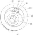
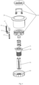
- FIGs. 1-7 respectively indicate: 10-button, 20-button body, 21-inner cavity, 30-thread member, 31-boss, 40-linkage member, 41-adjusting piece, 42-spring pin, 43-driving portion, 44-elastic member, 50-transmission rod, 60-thread member retaining cover.
- a flushing valve actuator includes a switch body, a switch mounted in the switch body, a thread member 30, and a linkage member 40 movable between a first position and a second position; when the linkage member 40 is located at the first position, the switch body drives the thread member 30 to rotate through the linkage member, and the switch body is locked or unlocked through the thread member 30; when the linkage member 40 is located at the second position, the linkage member 40 disconnects the linkage between the switch body and the thread member 30, and the switch body cannot be locked or unlocked through the thread member 30.
- the flushing valve actuator of the present disclosure may be installed on a water tank, a toilet or the like that contains a drain valve. When the switch body is rotated forward, the switch body can be locked on the water tank or the toilet through the thread member 30, and when the switch body is rotated backward, the switch body can be unlocked from the water tank or the toilet through the thread member 30.
- Embodiment 2 referring to FIG. 1 , on the basis of Embodiment 1, in this embodiment, the thread member 30 and the switch body are rotatably mounted together, and the linkage member 40 is movably mounted on the switch body. It is easy to understand that the linkage member 40 can also be movably mounted on the thread member 30.
- the switch is a button 10
- the button 10 includes a button decorative piece
- the switch body is a button body 20
- the thread member 30 is a hollow structure open at both ends; a transmission rod 50 penetrates through the thread member 30, and one end of the transmission rod 50 is connected to the switch.
- the flushing valve actuator also includes a button elastic member. After an external force pressing the button 10 is removed, under the influence of the button elastic member, the button 10 drives the transmission rod 50 to reset to initial positions together.
- an inner cavity 21 with a top opening is formed inside the button body 20, and the bottom of the inner cavity 21 is provided with a through hole.
- Both the button 10 and the linkage member 40 are movably installed in the inner cavity 21, and the thread member 30 rotatably penetrates through the through hole and is capable of being axially limited.
- a linkage fitting member on the thread member 30 described below is located in the inner cavity 21, and a threaded portion on the threaded member is located outside the button body 20.
- One end of the thread member 30 extends through the through hole into the inner cavity 21 and is close to the linkage member 40, and an end diameter of the thread member 30 at this end is greater than a diameter of the through hole to ensure that the thread member 30 will not fall off from the through hole.
- the linkage portion and the linkage fitting portion align in the axial direction of the thread member 30, and when the thread member 30 is rotated, the linkage portion abuts against the linkage fitting portion to form circumferential transmission fit.
- the linkage member 40 is located at the second position, the linkage portion and the linkage fitting portion misalign in the axial direction of the thread member 30, and the thread member 30 can rotate freely relative to the linkage member 40.
- the linkage member 40 includes an adjusting piece 41 and a spring pin 42, the spring pin 42 forms the linkage portion; a periphery of a portion of the thread member 30 located inside the inner cavity 21 of the switch body 20 is provided with a boss 31, and the boss 31 forms the linkage fitting portion.
- the flushing valve actuator further includes a thread member retaining cover 60.
- the bottom of the thread member retaining cover 60 is provided with a thread hole corresponding to a thread of the thread member 30, and the thread member retaining cover 60 is screwed into a portion of the thread member 30 extending out of the switch body, and the thread member 30 is rotatably mounted on the switch body through the thread member retaining cover 60 and an end of the thread member 30 located in the inner cavity 21.
- the adjusting piece 41 is toggled downward so that the adjusting piece 41 is located at a position where the retaining protrusion and the retaining groove are in retaining fit, and the adjusting piece 41 overcomes the elastic force of the elastic member so that the spring pin 42 and the boss 31 misalign in the axial direction of the thread member 30 (referring to FIG. 6 ), thereby releasing a linkage relationship between the button body 20 and the thread member 30.
- Embodiment 3 a flushing valve actuator with a clutch structure in the foregoing embodiment.
- a flushing valve actuator comprising a clutch structure, and a flushing valve of the present disclosure both include a switch, a switch body, a thread member and a clutch structure comprising a linkage member with a linkage function; a connection relationship between the switch body and the thread member can be switched by changing a position of the linkage member; when the linkage member is located at a first position, the switch body and the thread member are in a linkage relationship, the thread member is driven by rotating the switch body, to lock or unlock the thread member, thereby realizing the locking or unlocking of the switch body; when the linkage member is at a second position so that the linkage relationship between the switch body and the thread member is disconnected, the switch body and the thread member are relatively independent of each other, that is, the switch body cannot be locked or unlocked through the thread member, and the installed thread member cannot be screwed out even if the switch body is rotated, ensuring that the entire drain valve switch
Landscapes
- Engineering & Computer Science (AREA)
- Mechanical Engineering (AREA)
- Aviation & Aerospace Engineering (AREA)
- Health & Medical Sciences (AREA)
- Life Sciences & Earth Sciences (AREA)
- Hydrology & Water Resources (AREA)
- Public Health (AREA)
- Water Supply & Treatment (AREA)
- Sink And Installation For Waste Water (AREA)
- Sanitary Device For Flush Toilet (AREA)
- Mechanically-Actuated Valves (AREA)
Claims (11)
- Spülventilbetätiger, umfassend einen Schalterkörper (20), einen in dem Schalterkörper (20) montierten Schalter (10), ein Gewindeelement (30) und eine Kupplungsstruktur, die ein Gestängeelement (40) umfasst, dadurch gekennzeichnet, dass das Gestängeelement (40) im Gebrauch zwischen einer ersten Position und einer zweiten Position beweglich ist; wenn sich das Gestängeelement (40) in der ersten Position befindet, treibt der Schalterkörper (20) das Gewindeelement (30) an, um sich durch das Gestängeelement (40) zu drehen, wodurch die Verriegelung oder Entriegelung des gesamten Spülventilbetätigers an einer Installationsposition eines Wassertanks oder einer anderen Vorrichtung ermöglicht wird; wenn sich das Gestängeelement (40) in der zweiten Position befindet, unterbricht das Gestängeelement (40) die Verbindung zwischen dem Schalterkörper (20) und dem Gewindeelement (30), so dass das Gewindeelement (30) nicht angetrieben werden kann, um aus der Installationsposition herauszuschrauben, selbst wenn der Schalterkörper (20) gedreht wird.
- Spülventilbetätiger nach Anspruch 1, dadurch gekennzeichnet, dass das Gewindeelement (30) und der Schalterkörper (20) drehbar miteinander verbunden sind und das Gestängeelement (40) beweglich am Schalterkörper (20) oder am Gewindeelement (30) angebracht ist.
- Spülventilbetätiger nach Anspruch 1, dadurch gekennzeichnet, dass das Gestängeelement (40) einen Antriebsabschnitt (43) umfasst, und dass der Schalter (10) den Antriebsabschnitt (43) abdeckt, wenn der Schalter (10) sich in einer Ausgangsposition befindet; der Schalter (10) die Ausgangsposition verlässt, nachdem er angetrieben wurde, und den Antriebsabschnitt (43) zum Antrieb freigibt, so dass sich das Gestängeelement (40) zwischen der ersten Position und der zweiten Position bewegt.
- Spülventilbetätiger nach einem der Ansprüche 1 bis 3, dadurch gekennzeichnet, dass das Gewindeelement (30) mit einem Gestängepassabschnitt versehen ist und das Gestängeelement (40) mit einem entsprechenden Gestängeabschnitt versehen ist; wenn sich das Gestängeelement (40) in der ersten Position befindet, der Gestängeabschnitt und der Gestängepassabschnitt in Umfangsübertragungspassung sind; wenn sich das Gestängeelement (40) in der zweiten Position befindet, ist der Gestängeabschnitt vom Gestängepassabschnitt getrennt.
- Spülventilbetätiger nach Anspruch 4, dadurch gekennzeichnet, dass der Schalter (10) ein Knopf ist und der Schalterkörper (20) ein Knopfkörper ist; ein innerer Hohlraum (21) mit einer oberen Öffnung innerhalb des Knopfkörpers (20) ausgebildet ist und ein Boden des inneren Hohlraums mit einem Durchgangsloch versehen ist; sowohl der Knopf (10) als auch das Gestängeelement (40) beweglich in dem inneren Hohlraum (21) installiert sind, und das Gewindeelement (30) drehbar durch das Durchgangsloch hindurchgeht und axial begrenzt werden kann, und der Gestängepassabschnitt an dem Gewindeelement (30) in dem inneren Hohlraum (21) angeordnet ist und ein Gewindeabschnitt an dem Gewindeelement (30) außerhalb des Knopfkörpers (20) angeordnet ist.
- Spülventilbetätiger nach Anspruch 4, dadurch gekennzeichnet, dass sich das Gestängeelement (40) zwischen der ersten Position und der zweiten Position entlang einer axialen Richtung des Gewindeelements (30) bewegt; wenn das Gewindeelement (30) gedreht wird, auf einer Ebene senkrecht zu einer Achse des Gewindeelements (30), eine Projektionsbahn, die durch den Gestängepassabschnitt gezeichnet wird, teilweise mit einer Projektion des Gestängeabschnitts überlappt; wenn das Gestängeelement (40) an der ersten Position angeordnet ist, fluchten der Gestängeabschnitt und der Gestängepassabschnitt in der axialen Richtung des Gewindeelements (30), und wenn der Schalterkörper (20) gedreht wird, stößt der Gestängeabschnitt an den Gestängepassabschnitt, um eine Umfangsübertragungspassung zu bilden; wenn sich das Gestängeelement (40) in der zweiten Position befindet, fluchten der Gestängeabschnitt und der Gestängepassabschnitt in der axialen Richtung des Gewindeelements (30) falsch, und das Gewindeelement (30) kann sich relativ zum Gestängeelement (40) frei drehen.
- Spülventilbetätiger nach Anspruch 5, dadurch gekennzeichnet, dass das Gestängeelement (40) ein Einstellstück (41) und einen Federstift (42) umfasst, und der Federstift (42) den Gestängeabschnitt bildet; ein Umfang eines Abschnitts des Gewindeelements (30), der sich innerhalb des Schalterkörpers (20) befindet, ist mit einer Nabe (31) versehen, und die Nabe (31) bildet den Gestängepassabschnitt.
- Spülventilbetätiger nach Anspruch 7, dadurch gekennzeichnet, dass das Einstellstück (41) beweglich in einer im Schalterkörper (20) ausgebildeten Streifennut angebracht ist und eine Längsrichtung der Streifennut parallel zur Achse des Gewindeelements (30) verläuft, der Federstift (42) zwischen dem Einstellstück (41) und dem Schalterkörper (20) über ein elastisches Element (44) elastisch gelagert ist; das Einstellstück (41) und eine Seitenwand der Streifennut jeweils mit einem Haltevorsprung und einer Haltenut versehen sind; wenn sich das Gestängeelement (40) in der ersten Position befindet, das Einstellstück (41) sich in einer Position befindet, in der der Haltevorsprung und die Haltenut voneinander getrennt sind, und der Federstift (42) und die Nabe (31) unter dem Einfluss des elastischen Elements (44) in Umfangsübertragungspassung sind, wenn sich das Gestängeelement (40) in der zweiten Position befindet, befindet sich das Einstellstück (41) in einer Position, in der der Haltevorsprung und die Haltenut in Haltepassung sind, und das Einstellstück die elastische Kraft des elastischen Elements überwindet, so dass sich der Federstift (42) und die Nabe (31) in der axialen Richtung des Gewindeelements (30) verschieben; und ein Antriebsabschnitt (43) für den manuellen Antrieb oder den Antrieb eines Werkzeugs ist an einer Position des Einstellstücks (41) in der Nähe des Knopfes angeordnet.
- Spülventilbetätiger nach Anspruch 5, dadurch gekennzeichnet, dass das Gewindeelement (30) ein Ende hat, das sich im inneren Hohlraum (21) befindet und einen Enddurchmesser hat, der größer ist als ein Durchmesser des Durchgangslochs; und der Ablassventilschalter ferner eine Gewindeelement-Halteabdeckung (60) umfasst, wobei die Gewindeelement-Halteabdeckung (60) mit einem Gewindeloch versehen ist, das einem Gewinde des Gewindeelements (30) entspricht, wobei die Gewindeelement-Halteabdeckung (60) in einen Abschnitt des Gewindeelements (30) geschraubt wird, der sich aus dem Schalterkörper (20) heraus erstreckt, und das Gewindeelement (30) durch die Gewindeelement-Halteabdeckung (60) und das Ende des Gewindeelements (30), das sich in dem inneren Hohlraum (21) befindet, relativ drehbar an dem Schalterkörper (20) angebracht ist.
- Spülventilbetätiger nach Anspruch 1, dadurch gekennzeichnet, dass das Gewindeelement (30) eine an beiden Enden offene Hohlstruktur ist; eine Übertragungsstange (50) das Gewindeelement (30) durchdringt und ein mit dem Schalter (10) verbundenes Ende aufweist.
- Spülventil, umfassend den Spülventilbetätiger nach einem der Ansprüche 1 bis 10.
Applications Claiming Priority (2)
| Application Number | Priority Date | Filing Date | Title |
|---|---|---|---|
| CN201920214862.2U CN210066925U (zh) | 2019-02-20 | 2019-02-20 | 一种带离合结构的排水阀开关及排水阀 |
| PCT/CN2020/075634 WO2020169007A1 (zh) | 2019-02-20 | 2020-02-18 | 一种带离合结构的排水阀开关及排水阀 |
Publications (4)
| Publication Number | Publication Date |
|---|---|
| EP3929366A1 EP3929366A1 (de) | 2021-12-29 |
| EP3929366A4 EP3929366A4 (de) | 2022-03-30 |
| EP3929366B1 true EP3929366B1 (de) | 2025-04-02 |
| EP3929366C0 EP3929366C0 (de) | 2025-04-02 |
Family
ID=69432628
Family Applications (1)
| Application Number | Title | Priority Date | Filing Date |
|---|---|---|---|
| EP20758677.7A Active EP3929366B1 (de) | 2019-02-20 | 2020-02-18 | Ablassventilschalter mit kupplungsstruktur und ablassventil |
Country Status (6)
| Country | Link |
|---|---|
| EP (1) | EP3929366B1 (de) |
| CN (1) | CN210066925U (de) |
| ES (1) | ES3025658T3 (de) |
| MA (1) | MA55035A (de) |
| PL (1) | PL3929366T3 (de) |
| WO (1) | WO2020169007A1 (de) |
Families Citing this family (2)
| Publication number | Priority date | Publication date | Assignee | Title |
|---|---|---|---|---|
| CN210066925U (zh) * | 2019-02-20 | 2020-02-14 | 厦门瑞尔特卫浴科技股份有限公司 | 一种带离合结构的排水阀开关及排水阀 |
| CN116220160B (zh) * | 2023-03-14 | 2025-07-01 | 箭牌家居集团股份有限公司 | 旋钮装置和用水设备 |
Family Cites Families (10)
| Publication number | Priority date | Publication date | Assignee | Title |
|---|---|---|---|---|
| ES2117903B1 (es) * | 1992-11-12 | 1999-03-16 | Agullo Pablo Fominaya | Mejoras introducidas en la patente de invencion num. p-9202287/1, por: perfeccionamientos en descargadores de cisternas para inodoros. |
| KR20110003864U (ko) * | 2009-10-13 | 2011-04-20 | 주식회사 루트싸이언스 | 배수밸브 |
| ES2552663T3 (es) * | 2012-12-18 | 2015-12-01 | Geberit International Ag | Dispositivo de activación para una grifería de descarga |
| CN205189086U (zh) * | 2015-12-04 | 2016-04-27 | 厦门立业卫浴工业有限公司 | 一种排水阀按键座通用互换装置 |
| CN206080379U (zh) * | 2016-06-28 | 2017-04-12 | 厦门康谱卫浴科技有限公司 | 智能发光冲洗水箱按钮 |
| CN106195295B (zh) * | 2016-08-29 | 2018-08-28 | 张玉莲 | 离合结构 |
| CN206512804U (zh) * | 2017-02-24 | 2017-09-22 | 九牧厨卫股份有限公司 | 一种排水阀快速拆装装置及排水阀 |
| CN107237911B (zh) * | 2017-06-23 | 2023-08-18 | 厦门瑞尔特卫浴科技股份有限公司 | 一种排水阀的连接结构 |
| CN207109967U (zh) * | 2017-07-18 | 2018-03-16 | 厦门瑞尔特卫浴科技股份有限公司 | 一种排水阀的连接结构 |
| CN210066925U (zh) * | 2019-02-20 | 2020-02-14 | 厦门瑞尔特卫浴科技股份有限公司 | 一种带离合结构的排水阀开关及排水阀 |
-
2019
- 2019-02-20 CN CN201920214862.2U patent/CN210066925U/zh active Active
-
2020
- 2020-02-18 PL PL20758677.7T patent/PL3929366T3/pl unknown
- 2020-02-18 EP EP20758677.7A patent/EP3929366B1/de active Active
- 2020-02-18 ES ES20758677T patent/ES3025658T3/es active Active
- 2020-02-18 MA MA055035A patent/MA55035A/fr unknown
- 2020-02-18 WO PCT/CN2020/075634 patent/WO2020169007A1/zh not_active Ceased
Also Published As
| Publication number | Publication date |
|---|---|
| MA55035A (fr) | 2022-03-30 |
| ES3025658T3 (en) | 2025-06-09 |
| PL3929366T3 (pl) | 2025-08-11 |
| EP3929366A1 (de) | 2021-12-29 |
| WO2020169007A1 (zh) | 2020-08-27 |
| EP3929366C0 (de) | 2025-04-02 |
| EP3929366A4 (de) | 2022-03-30 |
| CN210066925U (zh) | 2020-02-14 |
Similar Documents
| Publication | Publication Date | Title |
|---|---|---|
| US4052092A (en) | Latch operating device including operating and latch connection improvements | |
| US9816258B2 (en) | Drain control assembly | |
| US9982455B2 (en) | Side mounted privacy lock for a residential door | |
| EP3929366B1 (de) | Ablassventilschalter mit kupplungsstruktur und ablassventil | |
| US9032560B2 (en) | Multi-flush mode toilet | |
| JPH0796864B2 (ja) | ドア及びその類似物内に取付けるタイプのラッチ構造体 | |
| US8382621B2 (en) | Electrical drive apparatus for valves | |
| ES2423316T3 (es) | Servoválvula con mecanismo de bloqueo | |
| EP3587683B1 (de) | Druckknopfvorrichtung für ablaufventil | |
| US20110099711A1 (en) | Driving construction for driving washbasin, Bidet, kitchen sink, bath tub, shower draining systems | |
| EP1681502B1 (de) | Befestigungsvorrichtung für Betätigungsgriff eines Wasserhahnes | |
| RU2307215C2 (ru) | Узел отцепляющего рычага | |
| CN214999735U (zh) | 阀门开关助力装置和阀门组件 | |
| JP2560776Y2 (ja) | 水槽用排水栓の操作部構造 | |
| KR101590841B1 (ko) | 밸브 구동기 | |
| CN213236278U (zh) | 一种水路控制盒及淋浴器 | |
| KR20160103269A (ko) | 푸쉬풀형 도어록 바디 | |
| CN103210156A (zh) | 马桶解扣杆装置 | |
| CN221482739U (zh) | 一种阀结构 | |
| CN2916293Y (zh) | 一种带密码锁的阀门 | |
| US20120266374A1 (en) | Flush Valve | |
| KR20180032858A (ko) | 디스크밸브용 구동기 | |
| KR200393331Y1 (ko) | 냉난방배관용 전동밸브의 구동기 | |
| JP2005299766A (ja) | ロック機構付き弁装置 | |
| CN111623165B (zh) | 一种水路控制盒及淋浴器 |
Legal Events
| Date | Code | Title | Description |
|---|---|---|---|
| STAA | Information on the status of an ep patent application or granted ep patent |
Free format text: STATUS: THE INTERNATIONAL PUBLICATION HAS BEEN MADE |
|
| PUAI | Public reference made under article 153(3) epc to a published international application that has entered the european phase |
Free format text: ORIGINAL CODE: 0009012 |
|
| STAA | Information on the status of an ep patent application or granted ep patent |
Free format text: STATUS: REQUEST FOR EXAMINATION WAS MADE |
|
| 17P | Request for examination filed |
Effective date: 20210920 |
|
| AK | Designated contracting states |
Kind code of ref document: A1 Designated state(s): AL AT BE BG CH CY CZ DE DK EE ES FI FR GB GR HR HU IE IS IT LI LT LU LV MC MK MT NL NO PL PT RO RS SE SI SK SM TR |
|
| RIN1 | Information on inventor provided before grant (corrected) |
Inventor name: ZHANG, RONGYU Inventor name: HONG, QICHENG Inventor name: WANG, XINGDONG |
|
| A4 | Supplementary search report drawn up and despatched |
Effective date: 20220225 |
|
| RIC1 | Information provided on ipc code assigned before grant |
Ipc: E03D 1/34 20060101ALN20220221BHEP Ipc: E03D 5/09 20060101ALI20220221BHEP Ipc: G05G 1/02 20060101ALI20220221BHEP Ipc: F16K 31/44 20060101ALI20220221BHEP Ipc: E03D 5/02 20060101AFI20220221BHEP |
|
| DAX | Request for extension of the european patent (deleted) | ||
| RAV | Requested validation state of the european patent: fee paid |
Extension state: MA Effective date: 20210920 |
|
| REG | Reference to a national code |
Ref country code: DE Ref legal event code: R079 Ref document number: 602020048748 Country of ref document: DE Free format text: PREVIOUS MAIN CLASS: E03D0001340000 Ipc: E03D0005020000 |
|
| GRAP | Despatch of communication of intention to grant a patent |
Free format text: ORIGINAL CODE: EPIDOSNIGR1 |
|
| STAA | Information on the status of an ep patent application or granted ep patent |
Free format text: STATUS: GRANT OF PATENT IS INTENDED |
|
| RIC1 | Information provided on ipc code assigned before grant |
Ipc: E03D 1/34 20060101ALN20240919BHEP Ipc: E03D 5/09 20060101ALI20240919BHEP Ipc: G05G 1/02 20060101ALI20240919BHEP Ipc: F16K 31/44 20060101ALI20240919BHEP Ipc: E03D 5/02 20060101AFI20240919BHEP |
|
| INTG | Intention to grant announced |
Effective date: 20241011 |
|
| GRAS | Grant fee paid |
Free format text: ORIGINAL CODE: EPIDOSNIGR3 |
|
| GRAA | (expected) grant |
Free format text: ORIGINAL CODE: 0009210 |
|
| STAA | Information on the status of an ep patent application or granted ep patent |
Free format text: STATUS: THE PATENT HAS BEEN GRANTED |
|
| AK | Designated contracting states |
Kind code of ref document: B1 Designated state(s): AL AT BE BG CH CY CZ DE DK EE ES FI FR GB GR HR HU IE IS IT LI LT LU LV MC MK MT NL NO PL PT RO RS SE SI SK SM TR |
|
| REG | Reference to a national code |
Ref country code: GB Ref legal event code: FG4D |
|
| REG | Reference to a national code |
Ref country code: CH Ref legal event code: EP |
|
| REG | Reference to a national code |
Ref country code: IE Ref legal event code: FG4D |
|
| REG | Reference to a national code |
Ref country code: DE Ref legal event code: R096 Ref document number: 602020048748 Country of ref document: DE |
|
| REG | Reference to a national code |
Ref country code: ES Ref legal event code: FG2A Ref document number: 3025658 Country of ref document: ES Kind code of ref document: T3 Effective date: 20250609 |
|
| U01 | Request for unitary effect filed |
Effective date: 20250430 |
|
| U07 | Unitary effect registered |
Designated state(s): AT BE BG DE DK EE FI FR IT LT LU LV MT NL PT RO SE SI Effective date: 20250508 |
|
| PG25 | Lapsed in a contracting state [announced via postgrant information from national office to epo] |
Ref country code: GR Free format text: LAPSE BECAUSE OF FAILURE TO SUBMIT A TRANSLATION OF THE DESCRIPTION OR TO PAY THE FEE WITHIN THE PRESCRIBED TIME-LIMIT Effective date: 20250703 Ref country code: NO Free format text: LAPSE BECAUSE OF FAILURE TO SUBMIT A TRANSLATION OF THE DESCRIPTION OR TO PAY THE FEE WITHIN THE PRESCRIBED TIME-LIMIT Effective date: 20250702 |
|
| PG25 | Lapsed in a contracting state [announced via postgrant information from national office to epo] |
Ref country code: HR Free format text: LAPSE BECAUSE OF FAILURE TO SUBMIT A TRANSLATION OF THE DESCRIPTION OR TO PAY THE FEE WITHIN THE PRESCRIBED TIME-LIMIT Effective date: 20250402 |
|
| PG25 | Lapsed in a contracting state [announced via postgrant information from national office to epo] |
Ref country code: RS Free format text: LAPSE BECAUSE OF FAILURE TO SUBMIT A TRANSLATION OF THE DESCRIPTION OR TO PAY THE FEE WITHIN THE PRESCRIBED TIME-LIMIT Effective date: 20250702 |
|
| PG25 | Lapsed in a contracting state [announced via postgrant information from national office to epo] |
Ref country code: IS Free format text: LAPSE BECAUSE OF FAILURE TO SUBMIT A TRANSLATION OF THE DESCRIPTION OR TO PAY THE FEE WITHIN THE PRESCRIBED TIME-LIMIT Effective date: 20250802 |
|
| PG25 | Lapsed in a contracting state [announced via postgrant information from national office to epo] |
Ref country code: SM Free format text: LAPSE BECAUSE OF FAILURE TO SUBMIT A TRANSLATION OF THE DESCRIPTION OR TO PAY THE FEE WITHIN THE PRESCRIBED TIME-LIMIT Effective date: 20250402 |
|
| PG25 | Lapsed in a contracting state [announced via postgrant information from national office to epo] |
Ref country code: SK Free format text: LAPSE BECAUSE OF FAILURE TO SUBMIT A TRANSLATION OF THE DESCRIPTION OR TO PAY THE FEE WITHIN THE PRESCRIBED TIME-LIMIT Effective date: 20250402 |
|
| PLBE | No opposition filed within time limit |
Free format text: ORIGINAL CODE: 0009261 |
|
| STAA | Information on the status of an ep patent application or granted ep patent |
Free format text: STATUS: NO OPPOSITION FILED WITHIN TIME LIMIT |
|
| REG | Reference to a national code |
Ref country code: CH Ref legal event code: L10 Free format text: ST27 STATUS EVENT CODE: U-0-0-L10-L00 (AS PROVIDED BY THE NATIONAL OFFICE) Effective date: 20260211 |
|
| 26N | No opposition filed |
Effective date: 20260105 |
|
| U20 | Renewal fee for the european patent with unitary effect paid |
Year of fee payment: 7 Effective date: 20260212 |