EP3928985B1 - Workpiece alignment and printing - Google Patents
Workpiece alignment and printing Download PDFInfo
- Publication number
- EP3928985B1 EP3928985B1 EP21173772.1A EP21173772A EP3928985B1 EP 3928985 B1 EP3928985 B1 EP 3928985B1 EP 21173772 A EP21173772 A EP 21173772A EP 3928985 B1 EP3928985 B1 EP 3928985B1
- Authority
- EP
- European Patent Office
- Prior art keywords
- workpiece
- workpieces
- support surface
- printing machine
- transport path
- Prior art date
- Legal status (The legal status is an assumption and is not a legal conclusion. Google has not performed a legal analysis and makes no representation as to the accuracy of the status listed.)
- Active
Links
Images




Classifications
-
- B—PERFORMING OPERATIONS; TRANSPORTING
- B41—PRINTING; LINING MACHINES; TYPEWRITERS; STAMPS
- B41M—PRINTING, DUPLICATING, MARKING, OR COPYING PROCESSES; COLOUR PRINTING
- B41M1/00—Inking and printing with a printer's forme
- B41M1/12—Stencil printing; Silk-screen printing
-
- H—ELECTRICITY
- H05—ELECTRIC TECHNIQUES NOT OTHERWISE PROVIDED FOR
- H05K—PRINTED CIRCUITS; CASINGS OR CONSTRUCTIONAL DETAILS OF ELECTRIC APPARATUS; MANUFACTURE OF ASSEMBLAGES OF ELECTRICAL COMPONENTS
- H05K3/00—Apparatus or processes for manufacturing printed circuits
- H05K3/10—Apparatus or processes for manufacturing printed circuits in which conductive material is applied to the insulating support in such a manner as to form the desired conductive pattern
- H05K3/12—Apparatus or processes for manufacturing printed circuits in which conductive material is applied to the insulating support in such a manner as to form the desired conductive pattern using thick film techniques, e.g. printing techniques to apply the conductive material or similar techniques for applying conductive paste or ink patterns
- H05K3/1216—Apparatus or processes for manufacturing printed circuits in which conductive material is applied to the insulating support in such a manner as to form the desired conductive pattern using thick film techniques, e.g. printing techniques to apply the conductive material or similar techniques for applying conductive paste or ink patterns by screen printing or stencil printing
- H05K3/1233—Methods or means for supplying the conductive material and for forcing it through the screen or stencil
-
- B—PERFORMING OPERATIONS; TRANSPORTING
- B41—PRINTING; LINING MACHINES; TYPEWRITERS; STAMPS
- B41F—PRINTING MACHINES OR PRESSES
- B41F15/00—Screen printers
- B41F15/08—Machines
-
- B—PERFORMING OPERATIONS; TRANSPORTING
- B41—PRINTING; LINING MACHINES; TYPEWRITERS; STAMPS
- B41F—PRINTING MACHINES OR PRESSES
- B41F15/00—Screen printers
- B41F15/08—Machines
- B41F15/0881—Machines for printing on polyhedral articles
-
- B—PERFORMING OPERATIONS; TRANSPORTING
- B41—PRINTING; LINING MACHINES; TYPEWRITERS; STAMPS
- B41F—PRINTING MACHINES OR PRESSES
- B41F15/00—Screen printers
- B41F15/14—Details
-
- B—PERFORMING OPERATIONS; TRANSPORTING
- B41—PRINTING; LINING MACHINES; TYPEWRITERS; STAMPS
- B41F—PRINTING MACHINES OR PRESSES
- B41F15/00—Screen printers
- B41F15/14—Details
- B41F15/16—Printing tables
- B41F15/18—Supports for workpieces
-
- B—PERFORMING OPERATIONS; TRANSPORTING
- B41—PRINTING; LINING MACHINES; TYPEWRITERS; STAMPS
- B41F—PRINTING MACHINES OR PRESSES
- B41F15/00—Screen printers
- B41F15/14—Details
- B41F15/16—Printing tables
- B41F15/18—Supports for workpieces
- B41F15/26—Supports for workpieces for articles with flat surfaces
-
- B—PERFORMING OPERATIONS; TRANSPORTING
- B41—PRINTING; LINING MACHINES; TYPEWRITERS; STAMPS
- B41F—PRINTING MACHINES OR PRESSES
- B41F15/00—Screen printers
- B41F15/14—Details
- B41F15/34—Screens, Frames; Holders therefor
-
- B—PERFORMING OPERATIONS; TRANSPORTING
- B41—PRINTING; LINING MACHINES; TYPEWRITERS; STAMPS
- B41F—PRINTING MACHINES OR PRESSES
- B41F15/00—Screen printers
- B41F15/14—Details
- B41F15/34—Screens, Frames; Holders therefor
- B41F15/36—Screens, Frames; Holders therefor flat
-
- B—PERFORMING OPERATIONS; TRANSPORTING
- B41—PRINTING; LINING MACHINES; TYPEWRITERS; STAMPS
- B41F—PRINTING MACHINES OR PRESSES
- B41F15/00—Screen printers
- B41F15/14—Details
- B41F15/44—Squeegees or doctors
-
- B—PERFORMING OPERATIONS; TRANSPORTING
- B41—PRINTING; LINING MACHINES; TYPEWRITERS; STAMPS
- B41F—PRINTING MACHINES OR PRESSES
- B41F21/00—Devices for conveying sheets through printing apparatus or machines
- B41F21/04—Grippers
-
- B—PERFORMING OPERATIONS; TRANSPORTING
- B41—PRINTING; LINING MACHINES; TYPEWRITERS; STAMPS
- B41F—PRINTING MACHINES OR PRESSES
- B41F21/00—Devices for conveying sheets through printing apparatus or machines
- B41F21/08—Combinations of endless conveyors and grippers
-
- B—PERFORMING OPERATIONS; TRANSPORTING
- B41—PRINTING; LINING MACHINES; TYPEWRITERS; STAMPS
- B41F—PRINTING MACHINES OR PRESSES
- B41F33/00—Indicating, counting, warning, control or safety devices
-
- B—PERFORMING OPERATIONS; TRANSPORTING
- B41—PRINTING; LINING MACHINES; TYPEWRITERS; STAMPS
- B41F—PRINTING MACHINES OR PRESSES
- B41F33/00—Indicating, counting, warning, control or safety devices
- B41F33/0009—Central control units
-
- B—PERFORMING OPERATIONS; TRANSPORTING
- B41—PRINTING; LINING MACHINES; TYPEWRITERS; STAMPS
- B41F—PRINTING MACHINES OR PRESSES
- B41F33/00—Indicating, counting, warning, control or safety devices
- B41F33/04—Tripping devices or stop-motions
- B41F33/12—Tripping devices or stop-motions for starting or stopping the machine as a whole
-
- B—PERFORMING OPERATIONS; TRANSPORTING
- B41—PRINTING; LINING MACHINES; TYPEWRITERS; STAMPS
- B41F—PRINTING MACHINES OR PRESSES
- B41F33/00—Indicating, counting, warning, control or safety devices
- B41F33/16—Programming systems for automatic control of sequence of operations
-
- H—ELECTRICITY
- H05—ELECTRIC TECHNIQUES NOT OTHERWISE PROVIDED FOR
- H05K—PRINTED CIRCUITS; CASINGS OR CONSTRUCTIONAL DETAILS OF ELECTRIC APPARATUS; MANUFACTURE OF ASSEMBLAGES OF ELECTRICAL COMPONENTS
- H05K3/00—Apparatus or processes for manufacturing printed circuits
- H05K3/0097—Processing two or more printed circuits simultaneously, e.g. made from a common substrate, or temporarily stacked circuit boards
-
- H—ELECTRICITY
- H05—ELECTRIC TECHNIQUES NOT OTHERWISE PROVIDED FOR
- H05K—PRINTED CIRCUITS; CASINGS OR CONSTRUCTIONAL DETAILS OF ELECTRIC APPARATUS; MANUFACTURE OF ASSEMBLAGES OF ELECTRICAL COMPONENTS
- H05K3/00—Apparatus or processes for manufacturing printed circuits
- H05K3/10—Apparatus or processes for manufacturing printed circuits in which conductive material is applied to the insulating support in such a manner as to form the desired conductive pattern
- H05K3/12—Apparatus or processes for manufacturing printed circuits in which conductive material is applied to the insulating support in such a manner as to form the desired conductive pattern using thick film techniques, e.g. printing techniques to apply the conductive material or similar techniques for applying conductive paste or ink patterns
- H05K3/1216—Apparatus or processes for manufacturing printed circuits in which conductive material is applied to the insulating support in such a manner as to form the desired conductive pattern using thick film techniques, e.g. printing techniques to apply the conductive material or similar techniques for applying conductive paste or ink patterns by screen printing or stencil printing
-
- H—ELECTRICITY
- H10—SEMICONDUCTOR DEVICES; ELECTRIC SOLID-STATE DEVICES NOT OTHERWISE PROVIDED FOR
- H10P—GENERIC PROCESSES OR APPARATUS FOR THE MANUFACTURE OR TREATMENT OF DEVICES COVERED BY CLASS H10
- H10P72/00—Handling or holding of wafers, substrates or devices during manufacture or treatment thereof
- H10P72/30—Handling or holding of wafers, substrates or devices during manufacture or treatment thereof for conveying, e.g. between different workstations
-
- H—ELECTRICITY
- H10—SEMICONDUCTOR DEVICES; ELECTRIC SOLID-STATE DEVICES NOT OTHERWISE PROVIDED FOR
- H10P—GENERIC PROCESSES OR APPARATUS FOR THE MANUFACTURE OR TREATMENT OF DEVICES COVERED BY CLASS H10
- H10P72/00—Handling or holding of wafers, substrates or devices during manufacture or treatment thereof
- H10P72/50—Handling or holding of wafers, substrates or devices during manufacture or treatment thereof for positioning, orientation or alignment
-
- B—PERFORMING OPERATIONS; TRANSPORTING
- B41—PRINTING; LINING MACHINES; TYPEWRITERS; STAMPS
- B41P—INDEXING SCHEME RELATING TO PRINTING, LINING MACHINES, TYPEWRITERS, AND TO STAMPS
- B41P2215/00—Screen printing machines
- B41P2215/10—Screen printing machines characterised by their constructional features
- B41P2215/11—Registering devices
- B41P2215/114—Registering devices with means for displacing the article
Definitions
- This invention relates to a method of printing workpieces, a computer program for controlling a printing machine, a printing machine and a method of aligning a workpiece.
- Industrial screen-printing machines typically apply a conductive print medium, such as solder paste, silver paste or conductive ink, onto a planar workpiece, such as a circuit board, by applying the conductive print medium through a pattern of apertures in a printing screen (sometimes referred to as a mask, foil or stencil) using an angled blade or squeegee.
- a conductive print medium such as solder paste, silver paste or conductive ink
- a planar workpiece such as a circuit board
- a conductive print medium such as solder paste, silver paste or conductive ink
- the workpiece support being capable of withstanding the pressure placed upon it during the printing operation, especially by the downward pressure applied by the squeegee, while maintaining the correct alignment of the workpiece.
- the area of the pattern is relatively small with respect to the area of the screen, it is possible to include more than one pattern within the screen, thus allowing more than one area of a board, or more than one board, to be printed simultaneously using the same screen.
- more than one relatively small screen may be used within the same printing machine to enable the more than one area of a board, or more than one board, to be printed simultaneously using respective screens.
- FIG. 1 schematically shows an example of such an assembly 1, here including a 2 x 4 array of individual support “towers" 2.
- Each tower 2 is topped with a support surface 3 upon which a workpiece (not shown) may be supported during a printing operation.
- each tower 2 is individually actuable to move in orthogonal directions X and Y, which would typically be in the horizontal plane, and also to rotate about an orthogonal Z axis, which would typically extend in the vertical direction to provide so-called theta correction.
- such movement may be advantageously provided through the use of a parallel kinematic actuation system within each tower. Other arrays of greater or smaller dimension are of course possible.
- FIGs. 2A-D schematically show, from above, the following basic steps which may be performed.
- a workpiece support assembly having a 1x4 tower array is shown.
- the individual towers of an array such as that shown in FIG. 1 must have a certain minimum spacing therebetween (i.e. the "pitch" of the array), so that each tower may move and / or rotate freely, without risk of collision with an adjacent tower in the array.
- the present invention seeks to overcome these restrictions in a cost-effective and robust manner.
- this aim is achieved by providing a more flexible stopping arrangement, and thereby selectively controlling the position of carriers within the printing machine.
- a workpiece support system comprising an array of at least two discrete support surfaces, each support surface for supporting a workpiece thereon in use, will be termed a “multiple support system".
- a multiple support system is a “multiple tower support system”, in which each support surface is located on a respective tower, such as described in GB1900058.7 for example.
- Other types of multiple tower support system exist, for example those in which parallel kinematics actuation is not used, or indeed multiple tower support systems in which the individual towers are not capable of the movement within any or all of the X, Y and theta ( ⁇ ) directions, and an example of such a system is described in WO2014166956A1 for example.
- each support surface need not be flat, but could for example be contoured so as to support non-planar workpieces, or have a plurality of pins extending therefrom to support the underside of workpieces which have features located on the underside thereof which cannot contact a support surface directly, such as placed electronics components, holes or vias.
- a method for printing workpieces having a first pitch along a horizontal transport path using a printing machine comprising:
- a printing machine for printing workpieces having a first pitch along a horizontal transport path comprising:
- a method for aligning a workpiece for printing within a printing machine comprising:
- FIGs. 3A-D An embodiment of the present invention is schematically shown with reference to FIGs. 3A-D .
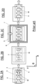
- FIGs. 3A-D show the interior of a printing machine from above ( FIGs. 3A and 3C ), and in a sectional side view along the section A-A ( FIGs. 3B and 3D ), and are aligned so that stationary components, such as towers 12, are shown at the same X-position and scale throughout the four figures.
- FIG. 3A schematically shows, from above, a printing area within a printing machine.
- Rails 10 are provided within the machine which define a horizontal transport path therebetween.
- the rails 10 may conveniently be provided with respective conveyors (not shown) to convey articles, in this case a carrier 14, along the transport path in the direction shown by the large arrow, which is generally denoted the X-direction in the art. Therefore, it is to be understood that the horizontal plane is equivalent to the X-Y plane as shown, while “Z" denotes the vertical direction.
- rails 10 are usually relatively moveable in the Y direction, so that articles of differing widths may be carried therebetween.
- the carrier 14 is shown transparently, so that the positioning of components underneath the carrier 14 can be seen.
- the carrier 14 shown in this embodiment includes eight workpiece receptacles 11, in a four by two matrix.
- each line of two adjacent workpiece receptacles 11 which lie in the same X position will be referred to as "columns”, so that here, four columns are shown, with, for convenience, the leftmost column referred to as the "first column”, and the rightmost column as the "fourth column” for example.
- Each workpiece receptacle 11 is designed to carry a single singulated workpiece (not shown for clarity).
- a workpiece receptacle In order to print a pattern 19 onto a workpiece, it is necessary to align a workpiece receptacle, and hence its received workpiece, above the support surface 13 (see FIG. 3B ) of a tower 12 of tooling (a multiple tower support system) arranged below the horizontal transport path.
- the patterns 19 are formed in a stencil or screen (not shown) located above the horizontal transport path.
- FIG. 3A in this embodiment four towers 12 are provided, in a two-by-two matrix.
- each tower 12 is provided with a support surface 13 at an upper end thereof for engaging with a respective workpiece in use, with the support surfaces 13 being discrete and horizontally spaced.
- the support surfaces 13 are shown as being flat, but in fact these may be contoured or profiled so as to support non-flat workpieces thereon in use.
- the towers 12 are provided on a tooling unit 16, which in turn is mounted on a rising table 15.
- the rising table 15 is vertically-movable between a lower, retracted position (shown in FIG. 3B ) and an upper, extended position (not shown), with the vertical distance travelled being shown as "H" in FIG.
- the support surfaces 13 are of smaller horizontal dimension than their respective towers 12, and are small enough to be able to project within a workpiece receptacle located directly above a respective tower 12 during raising of the rising table 15 to the extended position.
- each support surface 13 of each tower 12 are moveable within the horizontal or X-Y plane, upon receipt of suitable control signals received via the tooling unit 16. Yet more preferably, each support surface 13 is translatable both parallel to the horizontal path and orthogonally to the horizontal path within the horizontal or X-Y plane, and rotatable about a respective vertical or Z axis, similarly to the workpiece support assembly 1 shown in FIGs. 1 and 2 .
- the individual workpiece receptacles 11 have a relatively small pitch of length L in the X direction, while the towers 12 have a relatively large pitch in the X direction, and so it is impossible to locate all workpieces above respective support surfaces 13 at once.
- this problem is solved by enabling the carrier 14, and hence any workpieces carried thereby, to be stopped in more than one location along the X direction.
- a first physical stop 17 is provided proximate the rails to stop the carrier 14 at a first location along the horizontal path, in which workpieces carried in the second and fourth workpiece receptacle columns of the matrix directly overlie respective support surfaces 13, as shown in FIGs.
- the workpieces carried in the first and third workpiece receptacle columns of the matrix do not align with any support surfaces 13, but do overlie the rising table 15.
- the rising table 15 may be raised so that the support surfaces 13 engage with the workpieces in the second and fourth columns of the carrier 14.
- the workpieces may be aligned by suitable movement of the support surfaces 13 in the X-Y plane, and then printed with respective print patterns 19.
- the rising table 15 is then lowered back to the retracted position, so that printed workpieces are returned to their respective workpiece receptacles 11 in carrier 14.
- the carrier 14 is then transported to a second position which is a length L in the X direction, i.e. corresponding to the pitch of the workpiece receptacles 11.
- the carrier 14 is stopped at this second position by a second physical stop 18, so that it is stopped at the position shown in FIGs. 3C and 3D .
- both the first and second physical stops 17, 18 are retractable, so that they can be moved in and out of the horizontal path, to selectively stop the carrier 14 at either the first or second position.
- Controllable physical stops are known in the art per se, and so need not be described further here, but typically comprises an arm, rod or other barrier which may be selectively pivoted or translated into and out of the horizontal path by means of an actuator controlled by a processor, computer or other control means.
- the rising table 15 is then lowered back to the retracted position, so that the recently printed workpieces are returned to their respective workpiece receptacles 11 in carrier 14.
- the carrier 14, with its completely printed workpieces, may then be transported out of the printing machine along the horizontal transport path in the X-direction.
- the concept may be extended to allow efficient printing of carriers having workpiece receptacles at yet smaller pitches. For example, if a carrier having a six-by-two array of workpiece receptacles was used, and the pitch between workpiece receptacles was a third of the pitch between support surfaces, then all workpieces of the carrier could be printed in three print operations. In this case, preferably by printing columns three and six first, then moving the carrier forward by one pitch and printing columns two and five, then moving the carrier forward another one pitch and printing columns one and four.
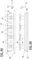
- FIG. 4A shows the interior of a printing machine from above, while FIG. 4B shows this in a sectional side view along the line B-B.
- Rails 20 define a horizontal transport path therebetween for carrierless workpieces W, with four workpieces W being shown. With such a configuration, the workpieces W are directly supported by, and conveyed along, rails 20.
- a tooling unit 26 which carries a plurality of towers 22 in a four-by-one matrix, with each tower 22 having a support surface 23 at an upper end thereof, the support surfaces being dimensioned and profiled as necessary to adequately support a workpiece W thereon.
- the tooling unit 26 is mounted onto rising table 25.
- the tooling i.e. tooling unit 26, towers 22 and support surfaces 23
- rising table 25 operate in an identical manner as in the previously-described embodiment.
- each support surface 23 engages with its respective overlying workpiece W and lifts it away from the rails 20.
- the workpieces are printed in a single print operation, and then may be returned to the rails 20 by lowering of the rising table 25 back to the retracted position.
- workpieces W can be prevented from stopping above support surfaces 23 of damaged or non-functional towers 22, for example, but instead stopped above an adjacent, fully functional, support surface 23.
- FIGs. 5A and 5B Another embodiment of the present invention is schematically shown with reference to FIGs. 5A and 5B . This is quite similar to that shown in FIGs. 4A and 4B , however here, rather than the workpieces W being directly supported by rails, they are placed in carriers, with all the workpieces of a plurality of carriers being printable in a single printing operation.
- FIG. 5A shows the interior of a printing machine from above, while FIG. 5B shows this in a sectional side view along the line C-C.
- Rails 30 define a horizontal transport path therebetween for carriers 34, with two carriers 34 being shown.
- two singulated workpieces W may be carried, here shown in a one-by-two array.
- each carrier 34 may be adapted to carry a plurality of workpieces in a non-linear array, such as two-by-two.
- a tooling unit 36 which carries a plurality of towers 32 in a four-by-one matrix, with each tower 32 having a support surface 33 at an upper end thereof, the support surfaces being dimensioned and profiled as necessary to adequately support a workpiece W thereon, other configurations of tooling are possible, if, for example, each carrier 34 carries workpieces W in a non-linear array.
- the tooling unit 36 is mounted onto rising table 35. With such a configuration, the carriers 34 are directly supported by, and conveyed along, rails 30, with carriers 34 able to enter the printing machine one at a time.
- This embodiment may also be combined with the embodiment shown in FIGs. 3A- 3D , so that more than one carrier 34 may be introduced into the printing area above the rising table 35, each carrier 34 carrying workpieces W at a smaller pitch than the pitch between support surfaces 33. In this case, additional stop elements would be required so that each carrier 34 could be stopped at a distance forward along the horizontal transport path equal to one workpiece pitch. Alternate columns of all carriers 34 would be printed in a single print operation, with the remaining columns printed in a second print operation.
- FIGs. 6A and 6B Another embodiment of the present invention is schematically shown with reference to FIGs. 6A and 6B .
- the arrangement is generally similar to that shown in FIGs. 4A and 4B , with carrierless workpieces W supported and conveyed directly by rails 40.
- the workpieces W are relatively large, so that each may directly overlie first and second adjacent support surfaces 43A, 43B of tooling of a multiple tower support system.
- the printing patterns 49 shown are correspondingly large.
- the tooling i.e. tooling unit 46, towers 42 and support surfaces 43A, 43B located at upper ends of respective towers 42
- rising table 45 operate in an identical manner as in the previously-described embodiments.
- each support surface 43 engages with its respective overlying workpiece W and lifts it away from the rails 40.
- alignment of the workpieces W is then performed, by moving the first and second support surfaces 43A, 43B while engaged with the overlying workpiece W.
- alignment is performed through coordinated movement of the support surfaces 43A, 43B in the horizontal or X-Y plane.
- the workpieces W may then be printed in a single print operation, de-aligned (i.e. returned to the positions at which they arrived above the rising table 45) if necessary and then returned to the rails 40 by lowering of the rising table 45 back to the retracted position.
- workpieces W can be prevented from stopping above support surfaces 43A, 43B of damaged or non-functional towers 42, for example, but instead stopped above alternative fully functional, support surfaces 43A, 43B.
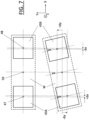
- FIG. 7 schematically shows how the first and second support surfaces 43A, 43B may be used to co-operatively align an overlying workpiece W.
- the top part of FIG. 7 shows, from above, a workpiece W (made transparent for clarity) in a first orientation, supported at each end thereof by respective support surfaces 43A and 43B.
- the geometric centre of workpiece W is shown as 50, while the geometric centres of support surfaces 43A and 43B are shown at 47 and 48 respectively.
- the lower part of FIG. 7 shows, again from above, the positioning of workpiece W and support surfaces 43A, 43B if the workpiece W is caused to rotate by an angle ⁇ about a vertical or Z axis passing through its centre 50, in an anticlockwise direction as shown.
- each support surface 43A, 43B cannot move relative to the overlying workpiece W, since to do so may cause damage to the workpiece W or any features present on its underside.
- the dashed lines show how the relative positions of the workpiece W and support surfaces 43A, 43B change with this rotation. It can be seen that the support surfaces 43A, 43B can be used to effect this rotation if the following conditions are met:
- support surfaces 43A and 43B are possible using a "multiple tower support system", such as that described in GB1900058.7 for example. While FIG. 7 only shows a rotation of workpiece W, it is of course also possible to cause a translation of workpiece W in the X-Y plane, by moving first and second support surfaces 43A and 43B an identical distance (i.e. moving in tandem) in the required direction of translation. Moreover, a combined rotation and translation of workpiece W is possible by superposing such movements.
- FIG. 7 uses adjacent support surfaces 43A and 43B which are spaced in the X direction, i.e. along the horizontal transport path, to enable cooperative alignment, similar alignment is possible if the adjacent support surfaces are instead spaced in the Y direction, i.e. orthogonal to the horizontal transport path. Such an arrangement is useful where the workpieces are relatively long in the Y direction so as to span the two adjacent support surfaces.
- the workpieces to be printed could be carried within a carrier.
- the above-described embodiments are exemplary only, and other possibilities and alternatives within the scope of the invention will be apparent to those skilled in the art.
- the transport control system may for example comprise a sensor associated with each of the first and second locations to sense the presence of a workpiece on the conveyor upstream of the respective location and pass a signal indicative of such presence to the conveyor control. In this way, full and flexible control of the workpieces and their stopping locations is enabled.
- n x m arrays in which "n" refers to the support surfaces spaced along the horizontal transport path or X direction and "m" refers to the support surfaces spaced orthogonal to that horizontal transport path, i.e. along the Y direction.
- n refers to the support surfaces spaced along the horizontal transport path or X direction
- m refers to the support surfaces spaced orthogonal to that horizontal transport path, i.e. along the Y direction.
Landscapes
- Engineering & Computer Science (AREA)
- Mechanical Engineering (AREA)
- Manufacturing & Machinery (AREA)
- Microelectronics & Electronic Packaging (AREA)
- Screen Printers (AREA)
- Printing Methods (AREA)
- Laser Beam Printer (AREA)
Description
- This invention relates to a method of printing workpieces, a computer program for controlling a printing machine, a printing machine and a method of aligning a workpiece.
- Industrial screen-printing machines typically apply a conductive print medium, such as solder paste, silver paste or conductive ink, onto a planar workpiece, such as a circuit board, by applying the conductive print medium through a pattern of apertures in a printing screen (sometimes referred to as a mask, foil or stencil) using an angled blade or squeegee. The same machines may also be used to print certain non-conductive media, such as glue or other adhesive, onto workpieces.
- To ensure high quality printing, it is necessary to support the workpiece so that the surface to be printed is parallel to the printing screen, generally horizontal, with the workpiece support being capable of withstanding the pressure placed upon it during the printing operation, especially by the downward pressure applied by the squeegee, while maintaining the correct alignment of the workpiece.
- Where the area of the pattern is relatively small with respect to the area of the screen, it is possible to include more than one pattern within the screen, thus allowing more than one area of a board, or more than one board, to be printed simultaneously using the same screen. Alternatively, more than one relatively small screen may be used within the same printing machine to enable the more than one area of a board, or more than one board, to be printed simultaneously using respective screens.
- A workpiece support assembly, capable of supporting and individually aligning a multiplicity of relatively small workpieces (commonly referred to as "singulated" workpieces) has been described in
GB1900058.7 FIG. 1 schematically shows an example of such anassembly 1, here including a 2 x 4 array of individual support "towers" 2. Eachtower 2 is topped with asupport surface 3 upon which a workpiece (not shown) may be supported during a printing operation. Furthermore, eachtower 2 is individually actuable to move in orthogonal directions X and Y, which would typically be in the horizontal plane, and also to rotate about an orthogonal Z axis, which would typically extend in the vertical direction to provide so-called theta correction. As described inGB1900058.7 - Typically, when printing singulated workpieces, a plurality of the workpieces will be located in a carrier, and the workpieces will be moved through the printing machine, and indeed between different machines along an assembly line, within the carrier.
FIGs. 2A-D schematically show, from above, the following basic steps which may be performed. InFIGs. 2A-D , for simplicity a workpiece support assembly having a 1x4 tower array is shown. - i) As shown in
FIG. 2A , acarrier 4, retaining a multiplicity of workpieces W therein, is transported into a printing machine (not shown) in the horizontal X-direction using a conveyor (not shown), and aligned within the printing machine by abutting it against aphysical stop element 6, so that the workpieces W are located directly aboverespective towers 2 of a workpiece support assembly on a rising table 5; - ii) the
towers 2 and respective overlying workpieces W are brought into contact, for example by lifting rising table 5 which carries the workpiece support assembly, so that the workpieces W are lifted from thecarrier 4; - iii) as shown in
FIG. 2B , each workpiece W is aligned as necessary by suitable actuation of the respectiveunderlying towers 2 in the X, Y and theta directions; - iv) the workpieces W are brought into contact with a patterned printing screen 7 (shown transparently for clarity in
FIG. 2C ), through further lifting of the rising table 5, theprinting screen 7 being tensioned within aframe 8; - v) as shown in
FIG. 2C , a print stroke is performed, using asqueegee 9 to deposit print medium onto the workpieces W through the apertures of theprinting screen 7; - vi) the workpieces W are brought out of contact with the
printing screen 7 and returned to thecarrier 4, by lowering the rising table 5; and - vii) as shown in
FIG. 2D , thephysical stop element 6 is moved out of engagement with thecarrier 4, and thecarrier 4, with its workpieces W, is transported out of the printing machine along the horizontal X direction. - Those skilled in the art will recognise that in order to function as intended, the individual towers of an array such as that shown in
FIG. 1 must have a certain minimum spacing therebetween (i.e. the "pitch" of the array), so that each tower may move and / or rotate freely, without risk of collision with an adjacent tower in the array. - When using a carrier loaded with singulated substrates, such a system generally works well, however there are some problems and restrictions faced when using such apparatus. For example:
- i) some users of printing machines may wish to print singulated workpieces located in a carrier in which the pitch of adjacent workpieces on a carrier is smaller than the corresponding pitch of the array;
- ii) operational flexibility and throughput is restricted, since only the workpieces on a single carrier can be printed in a single print stroke; and
- ii) for certain applications it may be preferable to print singulated workpieces without a carrier.
- The present invention seeks to overcome these restrictions in a cost-effective and robust manner.
- In accordance with the present invention, this aim is achieved by providing a more flexible stopping arrangement, and thereby selectively controlling the position of carriers within the printing machine.
- Hereafter, a workpiece support system comprising an array of at least two discrete support surfaces, each support surface for supporting a workpiece thereon in use, will be termed a "multiple support system". One example of a multiple support system is a "multiple tower support system", in which each support surface is located on a respective tower, such as described in
GB1900058.7 WO2014166956A1 for example. However, other types of multiple support system are possible which do not comprise towers, including for example a simple table with an upper support surface, the upper support surface including an array of regions each dedicated to supporting a respective workpiece, such that each region constitutes a support surface. It should also be understood that each support surface need not be flat, but could for example be contoured so as to support non-planar workpieces, or have a plurality of pins extending therefrom to support the underside of workpieces which have features located on the underside thereof which cannot contact a support surface directly, such as placed electronics components, holes or vias. - As background art may also be mentioned:
-
WO2014083605 ,US2008289518 ,JP2009248551 - iv)
US-A-6066206 - this document relates to a dual track stencil system. - In accordance with a first aspect of the present invention there is provided a method for printing workpieces having a first pitch along a horizontal transport path using a printing machine, the printing machine comprising:
- a rising table being vertically movable between a lower, retracted position and an upper, extended position, and
- tooling fitted to the rising table to be carried therewith, the tooling comprising a plurality of discrete and horizontally spaced support surfaces,
- the arrangement being such that in use workpieces are conveyed into and through the printing machine along the horizontal transport path, which is vertically above the tooling when the rising table is in the retracted position, and a support surface may be brought into engagement with a workpiece by raising the rising table toward the extended position, to enable a printing operation to be performed to print the engaged workpiece,
- the method comprising transporting a plurality of workpieces to be printed into the printing machine along the horizontal transport path,
- characterised in that the plurality of support surfaces are spaced along the horizontal transport path at a second pitch which is greater than the first pitch, and the transport is controlled such that each workpiece of the plurality of workpieces is stopped at respective first and second locations within the printing machine, the first and second locations being spaced along the horizontal transport path and each being located directly above the rising table when in its retracted position, with at least one of the first and second locations being directly located above a support surface of the tooling.
- In accordance with a second aspect of the present invention there is provided a computer program for controlling a printing machine to perform the method of the first aspect.
- In accordance with a third aspect of the present invention there is provided a printing machine for printing workpieces having a first pitch along a horizontal transport path, comprising:
- a rising table being vertically movable between a lower, retracted position and an upper, extended position,
- tooling fitted to the rising table to be carried therewith, the tooling comprising a plurality of discrete and horizontally spaced support surfaces,
- a conveyor operable to transport workpieces into and through the printing machine along the horizontal transport path which is vertically above the tooling when the rising table is in the retracted position, and
- characterised in that the plurality of support surfaces are spaced along the horizontal transport path at a second pitch which is greater than the first pitch, and
- characterised by a transport control system operable to selectively stop a workpiece on the conveyor at either a first or a second location within the printing machine, the first and second locations being spaced along the horizontal transport path and each being located directly above the rising table when in its retracted position, with at least one of the first and second locations being directly located above a support surface of the tooling.
- In accordance with a fourth aspect of the present invention there is provided a method for aligning a workpiece for printing within a printing machine, the printing machine comprising:
- a rising table being vertically movable between a lower, retracted position and an upper, extended position, and
- tooling fitted to the rising table to be carried therewith, the tooling comprising a plurality of discrete and horizontally spaced support surfaces, wherein the tooling comprises a plurality of towers, each support surface of the plurality of support surfaces being located at an upper end of a respective tower, and each support surface is moveable within the horizontal plane, and wherein each tower is individually actuable to translate its support surface both parallel to the horizontal path and orthogonally to the horizontal path within the horizontal plane, and rotate the support surface about a respective vertical axis,
- characterised in that the method comprises the steps of:
- i) transporting a workpiece into and through the printing machine along a horizontal transport path,
- ii) stopping the workpiece at a location in which the workpiece directly overlies first and second support surfaces of the plurality of support surfaces,
- iii) bringing the workpiece into engagement with both the first and second support surfaces, and
- iv) aligning the workpiece by moving the first and second support surfaces while engaged with the workpiece.
- Other specific aspects and features of the present invention are set out in the accompanying claims.
- The invention will now be described with reference to the accompanying drawings (not to scale), in which:
-
FIG. 1 schematically shows a known multiple tower support system; -
FIGs. 2A-D schematically show a printing operation for a known tower support system; -
FIGs. 3A and 3B schematically show a first step in a method according to the present invention from above and in a sectional side view respectively; -
FIGs. 3C and 3D schematically show a second step in a method according to the present invention from above and in a sectional side view respectively; -
FIGs. 4A and 4B schematically show another method according to the present invention, from above and in a sectional side view respectively; -
FIGs. 5A and 5B schematically show a further method according to the present invention, from above and in a sectional side view respectively; -
FIGs. 6A and 6B schematically show a yet further method according to the present invention, from above and in a sectional side view respectively; and -
FIG. 7 schematically shows a workpiece and support surfaces from above, illustrating a movement scheme therefor. - An embodiment of the present invention is schematically shown with reference to
FIGs. 3A-D . These show the interior of a printing machine from above (FIGs. 3A and 3C ), and in a sectional side view along the section A-A (FIGs. 3B and 3D ), and are aligned so that stationary components, such astowers 12, are shown at the same X-position and scale throughout the four figures. -
FIG. 3A schematically shows, from above, a printing area within a printing machine.Rails 10 are provided within the machine which define a horizontal transport path therebetween. Therails 10 may conveniently be provided with respective conveyors (not shown) to convey articles, in this case acarrier 14, along the transport path in the direction shown by the large arrow, which is generally denoted the X-direction in the art. Therefore, it is to be understood that the horizontal plane is equivalent to the X-Y plane as shown, while "Z" denotes the vertical direction. As will be recognised by those skilled in the art, rails 10 are usually relatively moveable in the Y direction, so that articles of differing widths may be carried therebetween. For clarity, thecarrier 14 is shown transparently, so that the positioning of components underneath thecarrier 14 can be seen. Thecarrier 14 shown in this embodiment includes eightworkpiece receptacles 11, in a four by two matrix. Hereafter, each line of twoadjacent workpiece receptacles 11 which lie in the same X position will be referred to as "columns", so that here, four columns are shown, with, for convenience, the leftmost column referred to as the "first column", and the rightmost column as the "fourth column" for example. Eachworkpiece receptacle 11 is designed to carry a single singulated workpiece (not shown for clarity). In order to print apattern 19 onto a workpiece, it is necessary to align a workpiece receptacle, and hence its received workpiece, above the support surface 13 (seeFIG. 3B ) of atower 12 of tooling (a multiple tower support system) arranged below the horizontal transport path. Thepatterns 19 are formed in a stencil or screen (not shown) located above the horizontal transport path. As shown inFIG. 3A , in this embodiment fourtowers 12 are provided, in a two-by-two matrix. - As most clearly seen in
FIG. 3B , eachtower 12 is provided with asupport surface 13 at an upper end thereof for engaging with a respective workpiece in use, with the support surfaces 13 being discrete and horizontally spaced. For clarity, the support surfaces 13 are shown as being flat, but in fact these may be contoured or profiled so as to support non-flat workpieces thereon in use. Thetowers 12 are provided on atooling unit 16, which in turn is mounted on a rising table 15. The rising table 15 is vertically-movable between a lower, retracted position (shown inFIG. 3B ) and an upper, extended position (not shown), with the vertical distance travelled being shown as "H" inFIG. 3B , in which the support surfaces 13 are brought up and into engagement with their overlying workpieces, to lift the workpieces away from thecarrier 14. In this extended position, a printing operation may be performed to print the engaged workpieces. The support surfaces 13 are of smaller horizontal dimension than theirrespective towers 12, and are small enough to be able to project within a workpiece receptacle located directly above arespective tower 12 during raising of the rising table 15 to the extended position. - In a preferred embodiment, the support surfaces 13 of each
tower 12 are moveable within the horizontal or X-Y plane, upon receipt of suitable control signals received via thetooling unit 16. Yet more preferably, eachsupport surface 13 is translatable both parallel to the horizontal path and orthogonally to the horizontal path within the horizontal or X-Y plane, and rotatable about a respective vertical or Z axis, similarly to theworkpiece support assembly 1 shown inFIGs. 1 and2 . - As can be most clearly seen in
FIG. 3A , theindividual workpiece receptacles 11 have a relatively small pitch of length L in the X direction, while thetowers 12 have a relatively large pitch in the X direction, and so it is impossible to locate all workpieces above respective support surfaces 13 at once. In accordance with the present invention, this problem is solved by enabling thecarrier 14, and hence any workpieces carried thereby, to be stopped in more than one location along the X direction. In the embodiment shown, a firstphysical stop 17 is provided proximate the rails to stop thecarrier 14 at a first location along the horizontal path, in which workpieces carried in the second and fourth workpiece receptacle columns of the matrix directly overlie respective support surfaces 13, as shown inFIGs. 3A and 3B . The workpieces carried in the first and third workpiece receptacle columns of the matrix do not align with any support surfaces 13, but do overlie the rising table 15. In this position, the rising table 15 may be raised so that the support surfaces 13 engage with the workpieces in the second and fourth columns of thecarrier 14. Once engaged and lifted from thecarrier 14, the workpieces may be aligned by suitable movement of the support surfaces 13 in the X-Y plane, and then printed withrespective print patterns 19. The rising table 15 is then lowered back to the retracted position, so that printed workpieces are returned to theirrespective workpiece receptacles 11 incarrier 14. - The
carrier 14 is then transported to a second position which is a length L in the X direction, i.e. corresponding to the pitch of theworkpiece receptacles 11. Thecarrier 14 is stopped at this second position by a secondphysical stop 18, so that it is stopped at the position shown inFIGs. 3C and 3D . Although not clearly shown, both the first and secondphysical stops carrier 14 at either the first or second position. Controllable physical stops are known in the art per se, and so need not be described further here, but typically comprises an arm, rod or other barrier which may be selectively pivoted or translated into and out of the horizontal path by means of an actuator controlled by a processor, computer or other control means. - As shown in
FIGs. 3C and 3D , at this second location along the horizontal path, workpieces carried in the first and third workpiece receptacle columns of the matrix directly overlie respective support surfaces 13. The previously-printed workpieces carried in the second and fourth workpiece receptacle columns of the matrix do not align with any support surfaces 13, but do overlie the rising table 15. In this position, the rising table 15 may be raised so that the support surfaces 13 engage with the workpieces in the first and third columns of thecarrier 14. Once engaged and lifted from thecarrier 14, the workpieces may be aligned by suitable movement of the support surfaces 13 in the X-Y plane, and then printed withrespective print patterns 19. The rising table 15 is then lowered back to the retracted position, so that the recently printed workpieces are returned to theirrespective workpiece receptacles 11 incarrier 14. Thecarrier 14, with its completely printed workpieces, may then be transported out of the printing machine along the horizontal transport path in the X-direction. - The concept may be extended to allow efficient printing of carriers having workpiece receptacles at yet smaller pitches. For example, if a carrier having a six-by-two array of workpiece receptacles was used, and the pitch between workpiece receptacles was a third of the pitch between support surfaces, then all workpieces of the carrier could be printed in three print operations. In this case, preferably by printing columns three and six first, then moving the carrier forward by one pitch and printing columns two and five, then moving the carrier forward another one pitch and printing columns one and four.
- Another embodiment of the present invention is schematically shown with reference to
FIGs. 4A and 4B . The method described here enables a plurality of workpieces W, which are not retained within a carrier, to be printed in a single printing operation.FIG. 4A shows the interior of a printing machine from above, whileFIG. 4B shows this in a sectional side view along the line B-B. Many components shown are similar to those previously described, and so need not be described at length here.Rails 20 define a horizontal transport path therebetween for carrierless workpieces W, with four workpieces W being shown. With such a configuration, the workpieces W are directly supported by, and conveyed along, rails 20. This naturally restricts the workpieces W to enter the printing machine one at a time, and so for this embodiment atooling unit 26 is provided which carries a plurality oftowers 22 in a four-by-one matrix, with eachtower 22 having asupport surface 23 at an upper end thereof, the support surfaces being dimensioned and profiled as necessary to adequately support a workpiece W thereon. Thetooling unit 26 is mounted onto rising table 25. - In order to improve printing efficiency, it is possible, in accordance with the present invention, to print four separate singulated workpieces W with a
printing pattern 29 in a single printing operation. This benefit is enabled by providing four separatephysical stop elements 21 along the horizontal transport path, each selectively operable to stop a respective workpiece W directly above arespective support surface 23. Thephysical stop elements 21 are operated under control of a control system (not shown), such as a computer, processor or the like. - The tooling (i.e. tooling
unit 26, towers 22 and support surfaces 23) and rising table 25 operate in an identical manner as in the previously-described embodiment. When the rising table 25 is raised to its extended position, eachsupport surface 23 engages with its respective overlying workpiece W and lifts it away from therails 20. Following any alignment of the workpiece W, for example by movement of thesupport surface 23 in the X-Y plane, the workpieces are printed in a single print operation, and then may be returned to therails 20 by lowering of the rising table 25 back to the retracted position. - Since the
physical stop elements 21 are selectively operable, workpieces W can be prevented from stopping above support surfaces 23 of damaged ornon-functional towers 22, for example, but instead stopped above an adjacent, fully functional,support surface 23. - Another embodiment of the present invention is schematically shown with reference to
FIGs. 5A and 5B . This is quite similar to that shown inFIGs. 4A and 4B , however here, rather than the workpieces W being directly supported by rails, they are placed in carriers, with all the workpieces of a plurality of carriers being printable in a single printing operation. -
FIG. 5A shows the interior of a printing machine from above, whileFIG. 5B shows this in a sectional side view along the line C-C. Many components shown are similar to those previously described, and so need not be described at length here.Rails 30 define a horizontal transport path therebetween forcarriers 34, with twocarriers 34 being shown. Within eachcarrier 34, two singulated workpieces W may be carried, here shown in a one-by-two array. Other configurations are possible, for example eachcarrier 34 may be adapted to carry a plurality of workpieces in a non-linear array, such as two-by-two. While as shown, atooling unit 36 is provided which carries a plurality oftowers 32 in a four-by-one matrix, with eachtower 32 having asupport surface 33 at an upper end thereof, the support surfaces being dimensioned and profiled as necessary to adequately support a workpiece W thereon, other configurations of tooling are possible, if, for example, eachcarrier 34 carries workpieces W in a non-linear array. Thetooling unit 36 is mounted onto rising table 35. With such a configuration, thecarriers 34 are directly supported by, and conveyed along, rails 30, withcarriers 34 able to enter the printing machine one at a time. - In order to improve printing efficiency, it is possible, in accordance with the present invention, to print the four separate singulated workpieces W carried by the two
carriers 34 with aprinting pattern 39 in a single printing operation. This benefit is enabled by providing two separatephysical stop elements 31 along the horizontal transport path, each selectively operable to stop arespective carrier 34 so that each of its workpieces W stop directly above arespective support surface 33. Thephysical stop elements 31 are operated under control of a control system (not shown), such as a computer, processor or the like. - This embodiment may also be combined with the embodiment shown in
FIGs. 3A- 3D , so that more than onecarrier 34 may be introduced into the printing area above the rising table 35, eachcarrier 34 carrying workpieces W at a smaller pitch than the pitch between support surfaces 33. In this case, additional stop elements would be required so that eachcarrier 34 could be stopped at a distance forward along the horizontal transport path equal to one workpiece pitch. Alternate columns of allcarriers 34 would be printed in a single print operation, with the remaining columns printed in a second print operation. - Another embodiment of the present invention is schematically shown with reference to
FIGs. 6A and 6B . Here the arrangement is generally similar to that shown inFIGs. 4A and 4B , with carrierless workpieces W supported and conveyed directly by rails 40. In this case however, the workpieces W are relatively large, so that each may directly overlie first and second adjacent support surfaces 43A, 43B of tooling of a multiple tower support system. Theprinting patterns 49 shown are correspondingly large. - In order to improve printing efficiency, it is possible, in accordance with the present invention, to print two separate singulated workpieces W with a
printing pattern 49 in a single printing operation. This benefit is enabled by providing two separatephysical stop elements 41 along the horizontal transport path, each selectively operable to stop a respective workpiece W directly above first and second support surfaces 43A, 43B. Thephysical stop elements 41 are operated under control of a control system (not shown), such as a computer, processor or the like. - The tooling (i.e. tooling
unit 46, towers 42 andsupport surfaces rails 40. In this embodiment, alignment of the workpieces W is then performed, by moving the first and second support surfaces 43A, 43B while engaged with the overlying workpiece W. In particular, alignment is performed through coordinated movement of the support surfaces 43A, 43B in the horizontal or X-Y plane. This is particularly beneficial when usingsupport surfaces rails 40 by lowering of the rising table 45 back to the retracted position. - Since the
physical stop elements 41 are selectively operable, workpieces W can be prevented from stopping above support surfaces 43A, 43B of damaged ornon-functional towers 42, for example, but instead stopped above alternative fully functional, support surfaces 43A, 43B. -
FIG. 7 schematically shows how the first and second support surfaces 43A, 43B may be used to co-operatively align an overlying workpiece W. The top part ofFIG. 7 shows, from above, a workpiece W (made transparent for clarity) in a first orientation, supported at each end thereof byrespective support surfaces support surfaces FIG. 7 shows, again from above, the positioning of workpiece W andsupport surfaces centre 50, in an anticlockwise direction as shown. It is important that eachsupport surface support surfaces - i) both first and second support surfaces 43A, 43B must also be rotate by θ in an anticlockwise direction,
- ii) simultaneously,
support surface 43A must move a distance Δx in the X direction and a distance Δy in the negative Y direction, and - iii) simultaneously,
support surface 43B must move a distance Δx in the negative X direction and a distance Δy in the Y direction. - The required movements of
support surfaces GB1900058.7 FIG. 7 only shows a rotation of workpiece W, it is of course also possible to cause a translation of workpiece W in the X-Y plane, by moving first and second support surfaces 43A and 43B an identical distance (i.e. moving in tandem) in the required direction of translation. Moreover, a combined rotation and translation of workpiece W is possible by superposing such movements. - While the embodiment described in
FIG. 7 usesadjacent support surfaces - In an alternative embodiment, the workpieces to be printed could be carried within a carrier.
- It should be noted that the concept of aligning workpieces by placing them on two spatially-separated support surfaces, as generally described with reference to
FIGs. 6A, 6B and7 need not require the workpieces to be stopped at respective first and second locations within the printing machine. For example, a single two-tower tooling could be used to align a single, relatively large, workpiece. - The above-described embodiments are exemplary only, and other possibilities and alternatives within the scope of the invention will be apparent to those skilled in the art. For example, while the above-described embodiments use physical stop elements, it is equally possible to use a transport control system comprising a conveyor control operable to control the operation of the conveyor to bring a workpiece to a stop at a selected location above the rising table. In such a case, the transport control system may for example comprise a sensor associated with each of the first and second locations to sense the presence of a workpiece on the conveyor upstream of the respective location and pass a signal indicative of such presence to the conveyor control. In this way, full and flexible control of the workpieces and their stopping locations is enabled.
- The methods described herein may be used with various sized arrays of workpieces and support surfaces. For example, the support surfaces, and respective towers, may be arranged in a wide range of n x m arrays in which "n" refers to the support surfaces spaced along the horizontal transport path or X direction and "m" refers to the support surfaces spaced orthogonal to that horizontal transport path, i.e. along the Y direction. In respect of the embodiments described with reference to
FIGs. 3 to 6 , any size array is possible in which n >= 2 and m >= 1. In respect of the embodiment described with reference toFIG. 7 , any size array is possible in which either n or m >= 1 and the other of m and n >= 2. -
- 1- Workpiece support assembly
- 2, 12, 22, 32, 42 - Tower
- 3, 13, 23, 33, 43A, 43B - Support surface
- 4, 14, 34 - Carrier
- 5, 15, 25, 35, 45 - Rising table
- 6 - Physical stop element
- 7 - Printing screen
- 8 - Frame
- 9 - Squeegee
- 10, 20, 30, 40 - Rails
- 11- Workpiece receptacles
- 16, 26, 36, 46 - Tooling unit
- 17 - First physical stop
- 18 - Second physical stop
- 19, 29, 39, 49 - Print pattern
- 21, 31, 41 - Physical stop elements
- 47 - Centre of
support surface 43A - 48 - Centre of
support surface 43B - 50 - Centre of workpiece W
- H - Height
- L - Length
- W - Workpiece
Claims (14)
- A method for printing workpieces (W) having a first pitch along a horizontal transport path using a printing machine, the printing machine comprising:a rising table (15, 25, 35, 45) being vertically movable between a lower, retracted position and an upper, extended position, andtooling (16, 26, 36, 46) fitted to the rising table (15, 25, 35, 45) to be carried therewith, the tooling (16, 26, 36, 46) comprising a plurality of discrete and horizontally spaced support surfaces (13, 23, 33, 43A, 43B),the arrangement being such that in use workpieces (W) are conveyed into and through the printing machine along the horizontal transport path, which is vertically above the tooling (16, 26, 36, 46) when the rising table (15, 25, 35, 45) is in the retracted position, and a support surface (13, 23, 33, 43A, 43B) may be brought into engagement with a workpiece (W) by raising the rising table (15, 25, 35, 45) toward the extended position, to enable a printing operation to be performed to print the engaged workpiece (W),the method comprising transporting a plurality of workpieces (W) to be printed into the printing machine along the horizontal transport path,wherein the plurality of support surfaces are spaced along the horizontal transport path at a second pitch which is greater than the first pitch, andthe transport is controlled such that each workpiece (W) of the plurality of workpieces (W) is stopped at respective first and second locations within the printing machine, the first and second locations being spaced along the horizontal transport path and each being located directly above the rising table (15, 25, 35, 45) when in its retracted position, with at least one of the first and second locations being directly located above a support surface (13, 23, 33, 43A, 43B) of the tooling (16, 26, 36, 46).
- The method of claim 1, wherein the workpieces (W) to be printed include at least one workpiece (W) in a first array, and at least one workpiece (W) in a second array, the workpieces (W) of the first and second arrays being interleaved along the horizontal transport path, the method comprising the steps of:i) controlling the transport to move the plurality of workpieces (W) along the horizontal transport path and stop a workpiece (W) of the first array at a first respective location in which it directly overlies a support surface (13, 23, 33, 43A, 43B), and stop a workpiece (W) of the second array at a first respective location in which it directly overlies the rising table (15, 25, 35, 45) but not a support surface (13, 23, 33, 43A, 43B),ii) raising the rising table (15, 25, 35, 45) to bring the workpiece (W) of the first array into engagement with its underlying support surface (13, 23, 33, 43A, 43B),iii) performing a first print operation to print the engaged workpiece (W) of the first array,iv) lowering the rising table (15, 25, 35, 45) to bring the printed workpiece (W) of the first array out of engagement with the support surface (13, 23, 33, 43A, 43B),v) controlling the transport to move the plurality of workpieces (W) along the horizontal transport path and stop the workpiece (W) of the second array at a second respective location in which it directly overlies a support surface (13, 23, 33, 43A, 43B), and stop the workpiece (W) of the first array at a second respective location in which it directly overlies the rising table (15, 25, 35, 45) but not a support surface (13, 23, 33, 43A, 43B),vi) raising the rising table (15, 25, 35, 45) to bring the workpiece (W) of the second array into engagement with its underlying support surface (13, 23, 33, 43A, 43 B),vii) performing a second print operation to print the engaged workpiece (W) in the second array, andviii) lowering the rising table (15, 25, 35, 45) to bring the printed workpiece (W) of the second array out of engagement with the support surface (13, 23, 33, 43A, 43B).
- The method of claim 2, wherein a workpiece (W) of the first array and a workpiece (W) of the second array are conveyed into the printing machine on a common carrier (14, 34), and in step i) the carrier (14, 34) is transported to a first carrier location along the horizontal transport path, and in step v) the carrier (14, 34) is transported to a second carrier location along the horizontal transport path.
- The method of claim 1, wherein a plurality of stopping locations are provided along the horizontal transport path, and the transport is controlled such that each workpiece (W) is stopped at a selected respective stopping location; optionally a workpiece (W) is stopped at each stopping location, and a single printing operation is performed to print every workpiece (W) which is stopped at a stopping location.
- The method of any preceding claim, wherein the tooling (16, 26, 36, 46) comprises a plurality of towers (12, 22, 32, 42), each support surface (13, 23, 33, 43A, 43B) being located at an upper end of a respective tower (12, 22, 32, 42), and each support surface (13, 23, 33, 43A, 43B) is moveable within the horizontal plane.
- The method of claim 5, wherein each support surface (13, 23, 33, 43A, 43B) is translatable both parallel to the horizontal path and orthogonally to the horizontal path within the horizontal plane, and rotatable about a respective vertical axis.
- The method of either of claims 5 and 6, comprising stopping a workpiece (W) at a first location in which it directly overlies first and second support surfaces, such that raising of the rising table (15, 25, 35, 45) toward the extended position brings both the first and second support surfaces (13, 23, 33, 43A, 43B) into engagement with the workpiece (W).
- The method of claim 7, comprising the step of adjusting the position and / or rotation of the workpiece (W) by moving the first and second support surfaces (13, 23, 33, 43A, 43B) when engaged with the workpiece (W).
- A computer program for controlling a printing machine to perform the method of any preceding claim.
- A printing machine for printing workpieces (W) having a first pitch along a horizontal transport path, comprising:a rising table (15, 25, 35, 45) being vertically movable between a lower, retracted position and an upper, extended position,tooling fitted to the rising table (15, 25, 35, 45) to be carried therewith, the tooling comprising a plurality of discrete and horizontally spaced support surfaces (13, 23, 33, 43A, 43B),a conveyor operable to transport workpieces into and through the printing machine along the horizontal transport path, which is vertically above the tooling when the rising table (15, 25, 35, 45) is in the retracted position, andwherein the plurality of support surfaces are spaced along the horizontal transport path at a second pitch which is greater than the first pitch, andthe printing machine further comprising a transport control system operable to selectively stop a workpiece (W) on the conveyor at either a first or a second location within the printing machine, the first and second locations being spaced along the horizontal transport path and each being located directly above the rising table (15, 25, 35, 45) when in its retracted position, with at least one of the first and second locations being directly located above a support surface (13, 23, 33, 43A, 43B) of the tooling.
- The printing machine of claim 10, wherein the transport control system comprises:a first physical stop element (17) operable to stop a workpiece (W) at the first location, anda second physical stop element (18) operable to stop a workpiece (W) at the second location.
- The printing machine of claim 10, wherein the transport control system comprises:
a conveyor control operable to control the operation of the conveyor to bring a workpiece (W) to a stop at a selected one of the first and second locations. - The printing machine of claim 12, wherein the transport control system comprises:
a sensor associated with each of the first and second locations to sense the presence of a workpiece (W) on the conveyor upstream of the respective location and pass a signal indicative of such presence to the conveyor control. - A method for aligning a workpiece (W) for printing within a printing machine, the printing machine comprising:a rising table (45) being vertically movable between a lower, retracted position and an upper, extended position, andtooling (46) fitted to the rising table (45) to be carried therewith, the tooling (46) comprising a plurality of discrete and horizontally spaced support surfaces (43A, 43B), wherein the tooling (46) comprises a plurality of towers (42), each support surface of the plurality of support surfaces (43A, 43B) being located at an upper end of a respective tower (42), and each support surface (43A, 43B) is moveable within the horizontal plane, and wherein each tower (42) is individually actuable to translate its support surface (43A, 43B) both parallel to the horizontal path and orthogonally to the horizontal path within the horizontal plane, and rotate the support surface (43A, 43B) about a respective vertical axis,wherein the method comprises the steps of:i) transporting a workpiece (W) into and through the printing machine along a horizontal transport path,ii) stopping the workpiece (W) at a location in which the workpiece (W) directly overlies first and second support surfaces of the plurality of support surfaces (43A, 43B),iii) bringing the workpiece (W) into engagement with both the first and second support surfaces (43A, 43B), andiv) aligning the workpiece (W) by moving the first and second support surfaces (43A, 43B) while engaged with the workpiece (W).
Priority Applications (1)
| Application Number | Priority Date | Filing Date | Title |
|---|---|---|---|
| RS20241322A RS66252B1 (en) | 2020-06-22 | 2021-05-13 | Workpiece alignment and printing |
Applications Claiming Priority (1)
| Application Number | Priority Date | Filing Date | Title |
|---|---|---|---|
| GB2009474.4A GB2596517A (en) | 2020-06-22 | 2020-06-22 | Workpiece alignment and printing |
Publications (3)
| Publication Number | Publication Date |
|---|---|
| EP3928985A1 EP3928985A1 (en) | 2021-12-29 |
| EP3928985B1 true EP3928985B1 (en) | 2024-09-18 |
| EP3928985C0 EP3928985C0 (en) | 2024-09-18 |
Family
ID=71838336
Family Applications (1)
| Application Number | Title | Priority Date | Filing Date |
|---|---|---|---|
| EP21173772.1A Active EP3928985B1 (en) | 2020-06-22 | 2021-05-13 | Workpiece alignment and printing |
Country Status (8)
| Country | Link |
|---|---|
| EP (1) | EP3928985B1 (en) |
| JP (1) | JP7307124B2 (en) |
| KR (1) | KR102523222B1 (en) |
| CN (1) | CN113895142B (en) |
| GB (1) | GB2596517A (en) |
| HU (1) | HUE069292T2 (en) |
| RS (1) | RS66252B1 (en) |
| TW (1) | TWI773302B (en) |
Families Citing this family (4)
| Publication number | Priority date | Publication date | Assignee | Title |
|---|---|---|---|---|
| GB2613575A (en) * | 2021-12-06 | 2023-06-14 | Asm Assembly Systems Singapore Pte Ltd | Offset printing of singulated workpieces |
| GB2619961A (en) | 2022-06-23 | 2023-12-27 | Asm Assembly Systems Singapore Pte Ltd | Alignment of singulated substrates |
| GB2640904A (en) * | 2024-05-09 | 2025-11-12 | Asmpt Smt Singapore Pte Ltd | Alignment systems and methods |
| GB2641783A (en) | 2024-06-12 | 2025-12-17 | Asmpt Smt Singapore Pte Ltd | Workpiece support assembly |
Family Cites Families (24)
| Publication number | Priority date | Publication date | Assignee | Title |
|---|---|---|---|---|
| JPH1076631A (en) * | 1996-09-02 | 1998-03-24 | Minoguruupu:Kk | Apparatus and method for conveying matter to be printed for screen printer |
| US6066206A (en) * | 1997-02-21 | 2000-05-23 | Speedline Technologies, Inc. | Dual track stenciling system with solder gathering head |
| US5873939A (en) * | 1997-02-21 | 1999-02-23 | Doyle; Dennis G. | Dual track stencil/screen printer |
| KR100250907B1 (en) * | 1997-12-17 | 2000-04-01 | 김재석 | Character printing device on the outside mirror of the vehicle |
| JP2004160732A (en) | 2002-11-11 | 2004-06-10 | Asahi Glass Co Ltd | Screen printing machine for simultaneous printing on multiple glass plates |
| JP4241639B2 (en) | 2005-02-14 | 2009-03-18 | セイコーエプソン株式会社 | Droplet discharge device and maintenance method of droplet discharge head |
| JP4356769B2 (en) * | 2007-05-22 | 2009-11-04 | パナソニック株式会社 | Screen printing apparatus and screen printing method |
| JP5023904B2 (en) * | 2007-09-11 | 2012-09-12 | パナソニック株式会社 | Screen printing device |
| JP5053913B2 (en) * | 2008-04-11 | 2012-10-24 | ミナミ株式会社 | Substrate position and angle correction device for screen printing machine |
| JP5514457B2 (en) * | 2009-03-06 | 2014-06-04 | アスリートFa株式会社 | Processing apparatus and method using mask |
| JP2011031588A (en) | 2009-08-06 | 2011-02-17 | Panasonic Corp | Screen printer and screen printing method |
| JP2011056761A (en) * | 2009-09-09 | 2011-03-24 | Micro-Tec Co Ltd | Printer and method for manufacturing print |
| JP5759348B2 (en) * | 2011-11-30 | 2015-08-05 | 株式会社Screenホールディングス | Pattern forming apparatus and pattern forming method |
| WO2014083605A1 (en) * | 2012-11-27 | 2014-06-05 | 富士機械製造株式会社 | Substrate printing device |
| US10889102B2 (en) * | 2013-04-08 | 2021-01-12 | ASM Assembly Systems Singapore Pte. Ltd | Workpiece referencing system for and method of referencing workpieces supported by a workpiece carrier |
| US9126398B2 (en) * | 2013-07-26 | 2015-09-08 | Asm Assembly Systems Singapore Pte Ltd | Apparatus for paste material printing, and printing method |
| JP6223091B2 (en) * | 2013-09-25 | 2017-11-01 | 株式会社Screenホールディングス | Position measuring apparatus, alignment apparatus, pattern drawing apparatus, and position measuring method |
| WO2015058302A1 (en) | 2013-10-23 | 2015-04-30 | Ats Automation Tooling Systems Inc. | Multiple part decoration system and method |
| CN105690754A (en) * | 2014-11-28 | 2016-06-22 | 上海普利生机电科技有限公司 | Photo-curing 3D printing method, equipment and image exposure system thereof |
| WO2017022127A1 (en) * | 2015-08-06 | 2017-02-09 | 富士機械製造株式会社 | Printing system and printing method |
| CN105668237B (en) * | 2016-04-21 | 2017-12-01 | 深圳市龙方自动化科技有限公司 | Full-automatic screen printer |
| CN205705715U (en) | 2016-06-23 | 2016-11-23 | 埃科产品创意开发(深圳)有限公司 | Full-automatic pad printer equipment |
| JP7108807B2 (en) | 2017-06-01 | 2022-07-29 | パナソニックIpマネジメント株式会社 | Screen printing system and screen printing method |
| DE112019003351T5 (en) | 2018-07-04 | 2021-04-01 | Panasonic Intellectual Property Management Co., Ltd. | STENCIL PRINTING DEVICE AND STENCIL PRINTING METHOD |
-
2020
- 2020-06-22 GB GB2009474.4A patent/GB2596517A/en not_active Withdrawn
-
2021
- 2021-05-07 TW TW110116522A patent/TWI773302B/en active
- 2021-05-13 HU HUE21173772A patent/HUE069292T2/en unknown
- 2021-05-13 RS RS20241322A patent/RS66252B1/en unknown
- 2021-05-13 EP EP21173772.1A patent/EP3928985B1/en active Active
- 2021-06-11 KR KR1020210075919A patent/KR102523222B1/en active Active
- 2021-06-17 CN CN202110670045.XA patent/CN113895142B/en active Active
- 2021-06-21 JP JP2021102335A patent/JP7307124B2/en active Active
Also Published As
| Publication number | Publication date |
|---|---|
| KR102523222B1 (en) | 2023-04-20 |
| CN113895142B (en) | 2023-05-09 |
| JP2022001434A (en) | 2022-01-06 |
| EP3928985A1 (en) | 2021-12-29 |
| TW202201148A (en) | 2022-01-01 |
| HUE069292T2 (en) | 2025-02-28 |
| JP7307124B2 (en) | 2023-07-11 |
| CN113895142A (en) | 2022-01-07 |
| RS66252B1 (en) | 2024-12-31 |
| GB2596517A (en) | 2022-01-05 |
| GB202009474D0 (en) | 2020-08-05 |
| EP3928985C0 (en) | 2024-09-18 |
| KR20210157872A (en) | 2021-12-29 |
| TWI773302B (en) | 2022-08-01 |
Similar Documents
| Publication | Publication Date | Title |
|---|---|---|
| EP3928985A1 (en) | Workpiece alignment and printing | |
| US12441098B2 (en) | Apparatus and method for the production of three-dimensional screen-printed workpieces | |
| JP2018086854A (en) | Apparatus and printing method for printing paste material | |
| KR102940603B1 (en) | Alignment of Singulated Substrates | |
| US20220203670A1 (en) | Apparatus and method for the production of three-dimensional screen-printed workpieces | |
| KR102407911B1 (en) | Alignment of singulated workpieces | |
| JP2009070867A (en) | Screen printing device | |
| US20220176628A1 (en) | Apparatus and method for the production of three-dimensional screen-printed workpieces | |
| EP4364949B1 (en) | Referencing system for singulated workpieces | |
| JP2010129866A (en) | Conductive ball mounting device | |
| EP4190562A1 (en) | Staggered printing of singulated workpieces | |
| KR20110020000A (en) | Screen printers and screen printing methods using them | |
| JP4858520B2 (en) | Screen printing machine and screen printing method | |
| US12172376B2 (en) | Method for the production of three-dimensional screen-printed workpieces | |
| US12629754B2 (en) | Apparatus and method for the production of three-dimensional screen-printed workpieces | |
| KR102702358B1 (en) | Identification code engraving apparatus for board | |
| US20220258462A1 (en) | Apparatus and method for the production of three-dimensional screen-printed workpieces | |
| JP4952697B2 (en) | Screen printing machine and screen printing method | |
| JPS6333979B2 (en) |
Legal Events
| Date | Code | Title | Description |
|---|---|---|---|
| PUAI | Public reference made under article 153(3) epc to a published international application that has entered the european phase |
Free format text: ORIGINAL CODE: 0009012 |
|
| STAA | Information on the status of an ep patent application or granted ep patent |
Free format text: STATUS: THE APPLICATION HAS BEEN PUBLISHED |
|
| AK | Designated contracting states |
Kind code of ref document: A1 Designated state(s): AL AT BE BG CH CY CZ DE DK EE ES FI FR GB GR HR HU IE IS IT LI LT LU LV MC MK MT NL NO PL PT RO RS SE SI SK SM TR |
|
| B565 | Issuance of search results under rule 164(2) epc |
Effective date: 20211109 |
|
| STAA | Information on the status of an ep patent application or granted ep patent |
Free format text: STATUS: REQUEST FOR EXAMINATION WAS MADE |
|
| 17P | Request for examination filed |
Effective date: 20220613 |
|
| RBV | Designated contracting states (corrected) |
Designated state(s): AL AT BE BG CH CY CZ DE DK EE ES FI FR GB GR HR HU IE IS IT LI LT LU LV MC MK MT NL NO PL PT RO RS SE SI SK SM TR |
|
| RAP3 | Party data changed (applicant data changed or rights of an application transferred) |
Owner name: ASMPT SMT SINGAPORE PTE. LTD |
|
| STAA | Information on the status of an ep patent application or granted ep patent |
Free format text: STATUS: EXAMINATION IS IN PROGRESS |
|
| 17Q | First examination report despatched |
Effective date: 20230509 |
|
| P01 | Opt-out of the competence of the unified patent court (upc) registered |
Effective date: 20230530 |
|
| GRAP | Despatch of communication of intention to grant a patent |
Free format text: ORIGINAL CODE: EPIDOSNIGR1 |
|
| STAA | Information on the status of an ep patent application or granted ep patent |
Free format text: STATUS: GRANT OF PATENT IS INTENDED |
|
| GRAJ | Information related to disapproval of communication of intention to grant by the applicant or resumption of examination proceedings by the epo deleted |
Free format text: ORIGINAL CODE: EPIDOSDIGR1 |
|
| STAA | Information on the status of an ep patent application or granted ep patent |
Free format text: STATUS: EXAMINATION IS IN PROGRESS |
|
| INTG | Intention to grant announced |
Effective date: 20240212 |
|
| INTC | Intention to grant announced (deleted) | ||
| RAP3 | Party data changed (applicant data changed or rights of an application transferred) |
Owner name: ASMPT SMT SINGAPORE PTE. LTD. |
|
| GRAP | Despatch of communication of intention to grant a patent |
Free format text: ORIGINAL CODE: EPIDOSNIGR1 |
|
| STAA | Information on the status of an ep patent application or granted ep patent |
Free format text: STATUS: GRANT OF PATENT IS INTENDED |
|
| INTG | Intention to grant announced |
Effective date: 20240613 |
|
| GRAS | Grant fee paid |
Free format text: ORIGINAL CODE: EPIDOSNIGR3 |
|
| GRAA | (expected) grant |
Free format text: ORIGINAL CODE: 0009210 |
|
| STAA | Information on the status of an ep patent application or granted ep patent |
Free format text: STATUS: THE PATENT HAS BEEN GRANTED |
|
| AK | Designated contracting states |
Kind code of ref document: B1 Designated state(s): AL AT BE BG CH CY CZ DE DK EE ES FI FR GB GR HR HU IE IS IT LI LT LU LV MC MK MT NL NO PL PT RO RS SE SI SK SM TR |
|
| REG | Reference to a national code |
Ref country code: GB Ref legal event code: FG4D |
|
| REG | Reference to a national code |
Ref country code: CH Ref legal event code: EP |
|
| REG | Reference to a national code |
Ref country code: IE Ref legal event code: FG4D |
|
| REG | Reference to a national code |
Ref country code: DE Ref legal event code: R096 Ref document number: 602021018854 Country of ref document: DE |
|
| U01 | Request for unitary effect filed |
Effective date: 20241010 |
|
| P04 | Withdrawal of opt-out of the competence of the unified patent court (upc) registered |
Free format text: CASE NUMBER: APP_58613/2024 Effective date: 20241026 |
|
| U07 | Unitary effect registered |
Designated state(s): AT BE BG DE DK EE FI FR IT LT LU LV MT NL PT RO SE SI Effective date: 20241030 |
|
| PG25 | Lapsed in a contracting state [announced via postgrant information from national office to epo] |
Ref country code: NO Free format text: LAPSE BECAUSE OF FAILURE TO SUBMIT A TRANSLATION OF THE DESCRIPTION OR TO PAY THE FEE WITHIN THE PRESCRIBED TIME-LIMIT Effective date: 20241218 |
|
| PG25 | Lapsed in a contracting state [announced via postgrant information from national office to epo] |
Ref country code: GR Free format text: LAPSE BECAUSE OF FAILURE TO SUBMIT A TRANSLATION OF THE DESCRIPTION OR TO PAY THE FEE WITHIN THE PRESCRIBED TIME-LIMIT Effective date: 20241219 |
|
| PG25 | Lapsed in a contracting state [announced via postgrant information from national office to epo] |
Ref country code: HR Free format text: LAPSE BECAUSE OF FAILURE TO SUBMIT A TRANSLATION OF THE DESCRIPTION OR TO PAY THE FEE WITHIN THE PRESCRIBED TIME-LIMIT Effective date: 20240918 |
|
| PG25 | Lapsed in a contracting state [announced via postgrant information from national office to epo] |
Ref country code: NO Free format text: LAPSE BECAUSE OF FAILURE TO SUBMIT A TRANSLATION OF THE DESCRIPTION OR TO PAY THE FEE WITHIN THE PRESCRIBED TIME-LIMIT Effective date: 20241218 Ref country code: HR Free format text: LAPSE BECAUSE OF FAILURE TO SUBMIT A TRANSLATION OF THE DESCRIPTION OR TO PAY THE FEE WITHIN THE PRESCRIBED TIME-LIMIT Effective date: 20240918 Ref country code: GR Free format text: LAPSE BECAUSE OF FAILURE TO SUBMIT A TRANSLATION OF THE DESCRIPTION OR TO PAY THE FEE WITHIN THE PRESCRIBED TIME-LIMIT Effective date: 20241219 |
|
| REG | Reference to a national code |
Ref country code: HU Ref legal event code: AG4A Ref document number: E069292 Country of ref document: HU |
|
| PG25 | Lapsed in a contracting state [announced via postgrant information from national office to epo] |
Ref country code: IS Free format text: LAPSE BECAUSE OF FAILURE TO SUBMIT A TRANSLATION OF THE DESCRIPTION OR TO PAY THE FEE WITHIN THE PRESCRIBED TIME-LIMIT Effective date: 20250118 |
|
| PG25 | Lapsed in a contracting state [announced via postgrant information from national office to epo] |
Ref country code: SM Free format text: LAPSE BECAUSE OF FAILURE TO SUBMIT A TRANSLATION OF THE DESCRIPTION OR TO PAY THE FEE WITHIN THE PRESCRIBED TIME-LIMIT Effective date: 20240918 |
|
| PG25 | Lapsed in a contracting state [announced via postgrant information from national office to epo] |
Ref country code: ES Free format text: LAPSE BECAUSE OF FAILURE TO SUBMIT A TRANSLATION OF THE DESCRIPTION OR TO PAY THE FEE WITHIN THE PRESCRIBED TIME-LIMIT Effective date: 20240918 |
|
| PG25 | Lapsed in a contracting state [announced via postgrant information from national office to epo] |
Ref country code: CZ Free format text: LAPSE BECAUSE OF FAILURE TO SUBMIT A TRANSLATION OF THE DESCRIPTION OR TO PAY THE FEE WITHIN THE PRESCRIBED TIME-LIMIT Effective date: 20240918 Ref country code: PL Free format text: LAPSE BECAUSE OF FAILURE TO SUBMIT A TRANSLATION OF THE DESCRIPTION OR TO PAY THE FEE WITHIN THE PRESCRIBED TIME-LIMIT Effective date: 20240918 |
|
| PG25 | Lapsed in a contracting state [announced via postgrant information from national office to epo] |
Ref country code: SK Free format text: LAPSE BECAUSE OF FAILURE TO SUBMIT A TRANSLATION OF THE DESCRIPTION OR TO PAY THE FEE WITHIN THE PRESCRIBED TIME-LIMIT Effective date: 20240918 |
|
| U20 | Renewal fee for the european patent with unitary effect paid |
Year of fee payment: 5 Effective date: 20250528 |
|
| PGFP | Annual fee paid to national office [announced via postgrant information from national office to epo] |
Ref country code: GB Payment date: 20250527 Year of fee payment: 5 |
|
| PGFP | Annual fee paid to national office [announced via postgrant information from national office to epo] |
Ref country code: RS Payment date: 20250505 Year of fee payment: 5 Ref country code: HU Payment date: 20250523 Year of fee payment: 5 |
|
| PLBE | No opposition filed within time limit |
Free format text: ORIGINAL CODE: 0009261 |
|
| STAA | Information on the status of an ep patent application or granted ep patent |
Free format text: STATUS: NO OPPOSITION FILED WITHIN TIME LIMIT |
|
| 26N | No opposition filed |
Effective date: 20250619 |
|
| REG | Reference to a national code |
Ref country code: CH Ref legal event code: H13 Free format text: ST27 STATUS EVENT CODE: U-0-0-H10-H13 (AS PROVIDED BY THE NATIONAL OFFICE) Effective date: 20251223 |
|
| PG25 | Lapsed in a contracting state [announced via postgrant information from national office to epo] |
Ref country code: CH Free format text: LAPSE BECAUSE OF NON-PAYMENT OF DUE FEES Effective date: 20250531 |
|
| PG25 | Lapsed in a contracting state [announced via postgrant information from national office to epo] |
Ref country code: MC Free format text: LAPSE BECAUSE OF FAILURE TO SUBMIT A TRANSLATION OF THE DESCRIPTION OR TO PAY THE FEE WITHIN THE PRESCRIBED TIME-LIMIT Effective date: 20240918 |
|
| PG25 | Lapsed in a contracting state [announced via postgrant information from national office to epo] |
Ref country code: IE Free format text: LAPSE BECAUSE OF NON-PAYMENT OF DUE FEES Effective date: 20250513 |