EP3928722A1 - Clot retrieval device with flexible collapsible frame - Google Patents
Clot retrieval device with flexible collapsible frame Download PDFInfo
- Publication number
- EP3928722A1 EP3928722A1 EP21180773.0A EP21180773A EP3928722A1 EP 3928722 A1 EP3928722 A1 EP 3928722A1 EP 21180773 A EP21180773 A EP 21180773A EP 3928722 A1 EP3928722 A1 EP 3928722A1
- Authority
- EP
- European Patent Office
- Prior art keywords
- expandable member
- retrieval device
- body segment
- clot retrieval
- clot
- Prior art date
- Legal status (The legal status is an assumption and is not a legal conclusion. Google has not performed a legal analysis and makes no representation as to the accuracy of the status listed.)
- Granted
Links
Images





Classifications
-
- A—HUMAN NECESSITIES
- A61—MEDICAL OR VETERINARY SCIENCE; HYGIENE
- A61B—DIAGNOSIS; SURGERY; IDENTIFICATION
- A61B17/00—Surgical instruments, devices or methods
- A61B17/22—Implements for squeezing-off ulcers or the like on inner organs of the body; Implements for scraping-out cavities of body organs, e.g. bones; for invasive removal or destruction of calculus using mechanical vibrations; for removing obstructions in blood vessels, not otherwise provided for
- A61B17/221—Gripping devices in the form of loops or baskets for gripping calculi or similar types of obstructions
-
- A—HUMAN NECESSITIES
- A61—MEDICAL OR VETERINARY SCIENCE; HYGIENE
- A61B—DIAGNOSIS; SURGERY; IDENTIFICATION
- A61B17/00—Surgical instruments, devices or methods
- A61B17/32—Surgical cutting instruments
- A61B17/3205—Excision instruments
- A61B17/3207—Atherectomy devices working by cutting or abrading; Similar devices specially adapted for non-vascular obstructions
- A61B17/320725—Atherectomy devices working by cutting or abrading; Similar devices specially adapted for non-vascular obstructions with radially expandable cutting or abrading elements
-
- A—HUMAN NECESSITIES
- A61—MEDICAL OR VETERINARY SCIENCE; HYGIENE
- A61B—DIAGNOSIS; SURGERY; IDENTIFICATION
- A61B90/00—Instruments, implements or accessories specially adapted for surgery or diagnosis and not covered by any of the groups A61B1/00 - A61B50/00, e.g. for luxation treatment or for protecting wound edges
- A61B90/39—Markers, e.g. radio-opaque or breast lesions markers
-
- A—HUMAN NECESSITIES
- A61—MEDICAL OR VETERINARY SCIENCE; HYGIENE
- A61B—DIAGNOSIS; SURGERY; IDENTIFICATION
- A61B17/00—Surgical instruments, devices or methods
- A61B2017/00831—Material properties
- A61B2017/00867—Material properties shape memory effect
-
- A—HUMAN NECESSITIES
- A61—MEDICAL OR VETERINARY SCIENCE; HYGIENE
- A61B—DIAGNOSIS; SURGERY; IDENTIFICATION
- A61B17/00—Surgical instruments, devices or methods
- A61B2017/00831—Material properties
- A61B2017/00902—Material properties transparent or translucent
- A61B2017/00915—Material properties transparent or translucent for radioactive radiation
- A61B2017/0092—Material properties transparent or translucent for radioactive radiation for X-rays
-
- A—HUMAN NECESSITIES
- A61—MEDICAL OR VETERINARY SCIENCE; HYGIENE
- A61B—DIAGNOSIS; SURGERY; IDENTIFICATION
- A61B17/00—Surgical instruments, devices or methods
- A61B17/22—Implements for squeezing-off ulcers or the like on inner organs of the body; Implements for scraping-out cavities of body organs, e.g. bones; for invasive removal or destruction of calculus using mechanical vibrations; for removing obstructions in blood vessels, not otherwise provided for
- A61B17/22031—Gripping instruments, e.g. forceps, for removing or smashing calculi
- A61B2017/22034—Gripping instruments, e.g. forceps, for removing or smashing calculi for gripping the obstruction or the tissue part from inside
-
- A—HUMAN NECESSITIES
- A61—MEDICAL OR VETERINARY SCIENCE; HYGIENE
- A61B—DIAGNOSIS; SURGERY; IDENTIFICATION
- A61B17/00—Surgical instruments, devices or methods
- A61B17/22—Implements for squeezing-off ulcers or the like on inner organs of the body; Implements for scraping-out cavities of body organs, e.g. bones; for invasive removal or destruction of calculus using mechanical vibrations; for removing obstructions in blood vessels, not otherwise provided for
- A61B2017/22038—Implements for squeezing-off ulcers or the like on inner organs of the body; Implements for scraping-out cavities of body organs, e.g. bones; for invasive removal or destruction of calculus using mechanical vibrations; for removing obstructions in blood vessels, not otherwise provided for with a guide wire
-
- A—HUMAN NECESSITIES
- A61—MEDICAL OR VETERINARY SCIENCE; HYGIENE
- A61B—DIAGNOSIS; SURGERY; IDENTIFICATION
- A61B17/00—Surgical instruments, devices or methods
- A61B17/22—Implements for squeezing-off ulcers or the like on inner organs of the body; Implements for scraping-out cavities of body organs, e.g. bones; for invasive removal or destruction of calculus using mechanical vibrations; for removing obstructions in blood vessels, not otherwise provided for
- A61B2017/22051—Implements for squeezing-off ulcers or the like on inner organs of the body; Implements for scraping-out cavities of body organs, e.g. bones; for invasive removal or destruction of calculus using mechanical vibrations; for removing obstructions in blood vessels, not otherwise provided for with an inflatable part, e.g. balloon, for positioning, blocking, or immobilisation
- A61B2017/22065—Functions of balloons
- A61B2017/22067—Blocking; Occlusion
-
- A—HUMAN NECESSITIES
- A61—MEDICAL OR VETERINARY SCIENCE; HYGIENE
- A61B—DIAGNOSIS; SURGERY; IDENTIFICATION
- A61B17/00—Surgical instruments, devices or methods
- A61B17/22—Implements for squeezing-off ulcers or the like on inner organs of the body; Implements for scraping-out cavities of body organs, e.g. bones; for invasive removal or destruction of calculus using mechanical vibrations; for removing obstructions in blood vessels, not otherwise provided for
- A61B2017/22079—Implements for squeezing-off ulcers or the like on inner organs of the body; Implements for scraping-out cavities of body organs, e.g. bones; for invasive removal or destruction of calculus using mechanical vibrations; for removing obstructions in blood vessels, not otherwise provided for with suction of debris
-
- A—HUMAN NECESSITIES
- A61—MEDICAL OR VETERINARY SCIENCE; HYGIENE
- A61B—DIAGNOSIS; SURGERY; IDENTIFICATION
- A61B17/00—Surgical instruments, devices or methods
- A61B17/22—Implements for squeezing-off ulcers or the like on inner organs of the body; Implements for scraping-out cavities of body organs, e.g. bones; for invasive removal or destruction of calculus using mechanical vibrations; for removing obstructions in blood vessels, not otherwise provided for
- A61B2017/22081—Treatment of vulnerable plaque
-
- A—HUMAN NECESSITIES
- A61—MEDICAL OR VETERINARY SCIENCE; HYGIENE
- A61B—DIAGNOSIS; SURGERY; IDENTIFICATION
- A61B17/00—Surgical instruments, devices or methods
- A61B17/22—Implements for squeezing-off ulcers or the like on inner organs of the body; Implements for scraping-out cavities of body organs, e.g. bones; for invasive removal or destruction of calculus using mechanical vibrations; for removing obstructions in blood vessels, not otherwise provided for
- A61B2017/22094—Implements for squeezing-off ulcers or the like on inner organs of the body; Implements for scraping-out cavities of body organs, e.g. bones; for invasive removal or destruction of calculus using mechanical vibrations; for removing obstructions in blood vessels, not otherwise provided for for crossing total occlusions, i.e. piercing
-
- A—HUMAN NECESSITIES
- A61—MEDICAL OR VETERINARY SCIENCE; HYGIENE
- A61B—DIAGNOSIS; SURGERY; IDENTIFICATION
- A61B17/00—Surgical instruments, devices or methods
- A61B17/22—Implements for squeezing-off ulcers or the like on inner organs of the body; Implements for scraping-out cavities of body organs, e.g. bones; for invasive removal or destruction of calculus using mechanical vibrations; for removing obstructions in blood vessels, not otherwise provided for
- A61B17/221—Gripping devices in the form of loops or baskets for gripping calculi or similar types of obstructions
- A61B2017/2212—Gripping devices in the form of loops or baskets for gripping calculi or similar types of obstructions having a closed distal end, e.g. a loop
-
- A—HUMAN NECESSITIES
- A61—MEDICAL OR VETERINARY SCIENCE; HYGIENE
- A61B—DIAGNOSIS; SURGERY; IDENTIFICATION
- A61B17/00—Surgical instruments, devices or methods
- A61B17/22—Implements for squeezing-off ulcers or the like on inner organs of the body; Implements for scraping-out cavities of body organs, e.g. bones; for invasive removal or destruction of calculus using mechanical vibrations; for removing obstructions in blood vessels, not otherwise provided for
- A61B17/221—Gripping devices in the form of loops or baskets for gripping calculi or similar types of obstructions
- A61B2017/2217—Gripping devices in the form of loops or baskets for gripping calculi or similar types of obstructions single wire changing shape to a gripping configuration
-
- A—HUMAN NECESSITIES
- A61—MEDICAL OR VETERINARY SCIENCE; HYGIENE
- A61B—DIAGNOSIS; SURGERY; IDENTIFICATION
- A61B17/00—Surgical instruments, devices or methods
- A61B17/32—Surgical cutting instruments
- A61B17/3205—Excision instruments
- A61B17/3207—Atherectomy devices working by cutting or abrading; Similar devices specially adapted for non-vascular obstructions
- A61B2017/320716—Atherectomy devices working by cutting or abrading; Similar devices specially adapted for non-vascular obstructions comprising means for preventing embolism by dislodged material
-
- A—HUMAN NECESSITIES
- A61—MEDICAL OR VETERINARY SCIENCE; HYGIENE
- A61B—DIAGNOSIS; SURGERY; IDENTIFICATION
- A61B90/00—Instruments, implements or accessories specially adapted for surgery or diagnosis and not covered by any of the groups A61B1/00 - A61B50/00, e.g. for luxation treatment or for protecting wound edges
- A61B90/39—Markers, e.g. radio-opaque or breast lesions markers
- A61B2090/3966—Radiopaque markers visible in an X-ray image
Definitions
- This invention relates to devices and methods of removing acute blockages from blood vessels. More specifically, the invention relates to removing obstructions from cerebral arteries in patients suffering acute ischemic stroke (AIS), from pulmonary arteries in patients suffering from pulmonary embolism (PE), from coronary native or graft vessels in patients suffering from myocardial infarction (MI), and from other peripheral arterial and venous vessels in which a clot or other obstruction (e.g. misplaced device, migrated device, large emboli, etc.) is causing an occlusion.
- AIS acute ischemic stroke
- PE pulmonary arteries in patients suffering from pulmonary embolism
- MI myocardial infarction
- a clot or other obstruction e.g. misplaced device, migrated device, large emboli, etc.
- Thromboembolism occurs when part or all of a thrombus breaks away from the blood vessel wall. This clot (now called an embolus) is then carried in the direction of blood flow. An ischemic stroke may result if the clot lodges in the cerebral vasculature. A pulmonary embolism may result if the clot originates in the venous system or in the right side of the heart and lodges in a pulmonary artery or branch thereof. Clots may also develop and block vessels locally without being released in the form of an embolus-this mechanism is common in the formation of coronary blockages.
- vasculature in the area in which the clot may be lodged is often fragile and delicate.
- neurovascular vessels are more fragile than similarly sized vessels in other parts of the body and are in a soft tissue bed. Excessive tensile forces applied on these vessels could result in perforations and hemorrhage.
- Pulmonary vessels are larger than those of the cerebral vasculature, but are also delicate in nature, particularly more superior vessels.
- the clot may comprise any of a range of morphologies and consistencies. Long strands of softer clot material may tend to lodge at bifurcations or trifurcations, resulting in multiple vessels being simultaneously occluded over significant lengths. More mature and organized clot material is likely to be less compressible than softer fresher clot, and under the action of blood pressure it may distend the compliant vessel in which it is lodged.
- the clots may not only range in shape and consistency, but also may vary greatly in length, even in any one given area of the anatomy. For example, clots occluding the middle cerebral artery of an ischemic stroke patient may range from just a few millimeters to several centimeters in length.
- Stent-like clot retrievers are being increasingly used to remove clot and other obstructions from cerebral vessels of acute stroke patients. These are self-expanding devices, similar in appearance to a stent attached to the end of a long shaft and are advanced through a microcatheter and deployed across clot obstructions in order to trap and retrieve them. They rely on a pinning mechanism to grab the clot by trapping the clot between the self-expanding stent-like body and the vessel wall.
- a stent-like clot retriever relies on its outward radial force (RF) to retain its grip on the clot. If the RF is too low the stent-like clot retriever will lose its grip on the clot, but if the RF is too high the stent-like clot retriever may damage the vessel wall and may require too much force to withdraw. Because clots vary in morphology across patients, RF required to grip the clot also varies. Because blood vessel fragility and geometry also varies across patients, RF required to reduce the risk of vessel trauma also varies.
- RF outward radial force
- some known stent-like clot retriever designs can lose their grip on a clot when withdrawn proximally around a bend in a tortuous vessel. This typically occurs because the struts of the stent-like clot retriever are placed in tension when it is retracted. This tension is due to friction between the device and the blood vessel and is increased if an additional load is applied load such as that provided by a clot. In a bend the struts on the outside of the bend are placed in higher tension than those on the inside. In order to attain the lowest possible energy state, the outside surface of the stent moves towards the inside surface of the bend, which reduces the tension in the struts, but also reduces the expanded diameter of the stent-like clot retriever.
- Some treatments rely on pinning the clot between the stent-like clot retriever and the vessel wall and thus may not restrain the clot effectively when passing a branch vessel or when passing into a vessel that is larger than the fully expanded diameter of the stent-like clot retriever.
- Pinning the clot between the stent-like clot retriever and the vessel wall in order to remove it from the vessel also results in high shear forces against the side of the clot as it is removed, potentially releasing fragments of the clot. If these fragments are not retained by the device, they may be released leading to further blockages in the distal vasculature.
- the stent-like clot retriever may be shorter than the clot itself.
- a device that is shorter than the clot is unlikely to be able to restore flow through the occluded area upon deployment, and thus the pressure gradient across the clot remains a significant impediment to its removal. Simply making such a device longer would likely render it difficult to track through tortuous anatomies and could be traumatic to the vasculature, taking more force to withdraw and potentially getting stuck and requiring surgery to remove.
- Examples disclosed herein generally include a clot retrieval device having an inner expandable member and an outer expandable member, each formed from respective strut frameworks such that the outer expandable member has larger cell openings than the inner expandable member.
- the outer expandable member can have multiple discontinuous body segments spaced apart in relation to a longitudinal axis of the device. Adjacent discontinuous body segments can be joined by a pair of tapered connecting arms that are able to bend with a small radius of curvature compared to the body segments. This small radius of curvature can have a range of values depending on the tortuosity of the vasculature the device is expanded in.
- the body segments can include radiopaque markers positioned to illustrate a circumference of the respective body segment and slightly staggered in relation to a longitudinal axis of the device such that the markers nest when the device is collapsed for delivery.
- An example clot retrieval device has a collapsed configuration and an expanded configuration.
- the clot retrieval device is configured to remove clot from a blood vessel.
- the clot retrieval device has an inner expandable member and an outer expandable member.
- the inner expandable member has a first framework of struts and the outer expandable member has a second framework of struts.
- the second framework at least partially radially surrounds the inner expandable member.
- Closed cells of the second framework of the outer expandable member can be larger than closed cells of the first framework of the inner expandable member.
- the outer expandable member can have a first and a second body segment connected by two connecting arms, wherein the first body segment is positioned in a proximal direction in relation the second body segment.
- Each of the two connecting arms respectively can have a tapered shape that is wider where the arm is near the first, proximal body segment and narrower where the arm is near the second, distal body segment.
- the outer expandable member can have additional body segments connected to the first and/or second body segment by additional connecting arms.
- the outer expandable member can have at least two inlet mouths in the second framework including a pair of inlet mouths between the first and second body segments.
- Each of the two inlet mouths between the first and second body segment can have a respective opening bounded by the first body segment, the second body segment, and the two connecting arms.
- the first body segment can have at least two pairs of struts each terminating in a respective distal apex and forming a proximal boundary of a respective inlet mouth of the two inlet mouths.
- the two connecting arms between the first and second body segments of the outer expandable member can extend substantially parallel to a longitudinal axis of the device.
- the two connecting arms between the first and second body segments of the outer expandable member can be positioned approximately 180° from each other about a circumference of the outer expandable member.
- the first body segment and the second body segment can be connected to each other solely via the two connecting arms.
- Each of the two connecting arms can be configured to bend with a curvature having a radius smaller than a radius of curvature of a majority of struts of the first body segment and the second body segment as the clot retrieval device is pulled proximally through a tubular vasculature comprising a bend of about 180°.
- the outer expandable member can have three or more body segments each shaped substantially similarly to the first body segment and the second body segment.
- the outer expandable member can include pairs of tapered connecting arms such that each respective pair of tapered connecting arms joins longitudinally adjacent body segments of the three or more body segments.
- the tapered connecting arms can be shaped and oriented similarly to the connecting arms between the first and second body segments.
- One or both of the first and second body segments can respectively include four or more radiopaque markers positioned around a circumference of the respective body segment.
- each of the radiopaque markers can be offset from adjacent radiopaque markers of the four or more radiopaque markers.
- the markers can be offset from adjacent radiopaque makers in relation to a longitudinal axis of the device.
- alternating radiopaque markers of the four or more radiopaque markers can be aligned in a plane orthogonal to the longitudinal axis.
- the first body segment can include a first set of four or more radiopaque markers.
- the second body segment can include a second set of four or more radiopaque markers.
- the first and second sets of four or more radiopaque markers are spaced approximately 8 millimeters apart, measured in the direction of the longitudinal axis.
- the first and second sets of four or more radiopaque markers are spaced approximately 10 millimeters apart, measured in the direction of the longitudinal axis.
- Each of the four or more radiopaque markers can include radiopaque material positioned in an eyelet.
- At least two of the four or more radiopaque markers can be aligned, in the direction of the longitudinal axis, with a respective connecting arm of the two connecting arms.
- Another example clot retrieval device can have a collapsed configuration and an expanded configuration.
- the clot retrieval device is configured to remove clot from a blood vessel. Structures and functionality of this example clot retrieval device are combinable with structures and features of the previous example clot retrieval device.
- the example clot retrieval device includes an inner expandable member having a first framework of struts and an outer expandable member having a second framework of struts.
- the second framework of struts can form closed cells larger than closed cells of the first framework of inner expandable member.
- the second framework can at least partially radially surround the first framework of the inner expandable member.
- the example clot retrieval device can include four or more radiopaque markers affixed to the second framework of struts and positioned to indicate a circumference of the outer expandable member.
- the radiopaque markers can be further positioned such that when the clot retrieval device is in the collapsed configuration, each of the radiopaque markers is offset, in relation to a longitudinal axis of the device to respective circumferentially adjacent radiopaque markers.
- the outer expandable member can include discontinuous body segments spaced apart from each other in the direction of the longitudinal axis.
- the radiopaque markers can be positioned to indicate a circumference of a body segment of the discontinuous body segments.
- the example clot retrieval device can include a first body segment and a second body segment, wherein the first body segment is positioned in a proximal direction in relation the second body segment.
- the outer expandable member can include two connecting arms joining the first body segment to the second body segment. Each of the two connecting arms can respectively have a tapered shape that is wider near the proximal, first body segment and narrower near the distal, second body segment.
- At least two of the four or more radiopaque markers can be aligned, in the direction of the longitudinal axis, with a respective connecting arm of the two connecting arms.
- the outer expandable member can include two inlet mouths in the second framework.
- Each of the two inlet mouths can include a respective opening bounded by the first body segment, the second body segment, and the two connecting arms.
- the first body segment can include the four or more radiopaque markers forming a first set of markers
- the second body segment can include a second set of four or more radiopaque markers positioned to indicate a circumference of the second body segment.
- the second set of radiopaque markers can be positioned such that when the clot retrieval device is in the collapsed configuration, each of the radiopaque markers of the second set is offset, in relation to a longitudinal axis of the device to respective adjacent radiopaque markers of the second set. Markers in the first set of radiopaque markers can be similarly offset.
- the two connecting arms can be positioned approximately 180° from each other about a circumference of the outer expandable member.
- distal or proximal are used in the following description with respect to a position or direction relative to the treating physician.
- distal or disally are a position distant from or in a direction away from the physician.
- Proximal or “proximally” or “proximate” are a position near or in a direction toward the physician.
- Accessing cerebral, coronary and pulmonary vessels involves the use of a number of commercially available products and conventional procedural steps. Access products such as guidewires, guide catheters, angiographic catheters and microcatheters are described elsewhere and are regularly used in catheter lab procedures. It is assumed in the descriptions below that these products and methods are employed in conjunction with the device and methods of this invention and do not need to be described in detail.
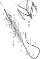
- Figure 1A shows a distal portion of an example clot retrieval device 100 in an expanded configuration.
- the clot retrieval device 100 generally extends to define a longitudinal axis A-A and has a distal coil 108 at its distal end, an outer expandable member 102 and an inner expandable member 103 extending proximally and coaxially from the distal coil 108, and a proximal coil 104 extending proximally from the outer expandable member 102 and the inner expandable member 103.
- the device 100 can include additional features such as an elongate shaft 106, a sleeve 105, and indicator bands 107.
- the device 100 can include a distal junction or collar 109 joining the distal coil 108 to the outer expandable member 102 and the inner expandable member 103.
- the device 100 can include a proximal junction or collar 112 joining the proximal coil 104 to the outer expandable member 102 and the inner expandable member 103.
- the junctions 109, 112 can be constructed as usable with a clot retrieval device having two expandable layers 102, 103 such as described in U.S. 10,390,850 incorporated herein by reference as if set forth herein in its entirety.
- Figure 1B shows a close-up of a portion of the clot retrieval device illustrated in Figure 1A , the portion including a tapered strut according to aspects of the present invention.
- Figure 2A shows a plan view of a first side of the clot retrieval device 100.
- Figure 2B shows the view clot retrieval device 100 as illustrated in Figure 2A having the inner expandable member 103 removed for the purpose of illustration.
- Figure 2C shows the view of the clot retrieval device 100 as illustrated in Figure 2A having the outer expandable member 102 removed for the purpose of illustration.
- Figure 3A shows a plan view of a second side of the clot retrieval device 100, the second side viewed at 90° from the first side view illustrated in Figure 2A .
- Figure 3B shows the view clot retrieval device 100 as illustrated in Figure 3A having the inner expandable member 103 removed for the purpose of illustration.
- Figure 3C shows the view of the clot retrieval device 100 as illustrated in Figure 3A having the outer expandable member 102 removed for the purpose of illustration.
- Figure 4A shows a linear view of the outer expandable member 102 cut along a line B-B indicated in Figures 2B and 3B and flattened.
- Figure 4B shows a close-up of a portion of the outer expandable member 102 as indicated in Figure 4A .
- Figure 4C shows a close-up of a portion of the outer expandable member 102 as indicated in Figure 4B .
- Figure 5A shows a plan view of a distal end of the clot retrieval device 100.
- Figure 5B shows the view of the clot retrieval device 100 as illustrated in Figure 5A having the inner expandable member 103 removed for the purpose of illustration.
- Figure 5C shows the view of the clot retrieval device 100 as illustrated in Figure 5A having the outer expandable member 102 removed for the purpose of illustration.
- the outer expandable member 102 can include tapered struts 129, 130 joining body segments 126, 127, 128.
- the tapered struts 129, 130 are shaped to provide flexibility to the outer expandable member 102 to facilitate withdraw of the device 100 from tortuous vascular when an obstruction is at least partially confined by the outer expandable member 102.
- the tapered struts 129, 130 are shaped to promote apposition of the outer expandable member 102 circumferentially to blood vessel walls as the device 100 is withdrawn through tortuous vasculature when an obstruction is at least partially confined by the outer expandable member 102.
- the outer expandable member 103 can include staggered radiopaque markers positioned to facilitate visualization of the device 100 during treatment while also maintaining a small profile collapsed configuration of the outer expandable member 102 to facilitate traverse of the collapsed device 100 across a clot or other obstruction.
- the outer expandable member 102 and inner expandable member 103 are collapsible into a restraining sheath (e.g. microcatheter) sized to traverse a clot or other obstruction.
- the outer expandable member 102 and inner expandable member 103 are each configured to self-expand upon release from the restraining sheath.
- the device 100 can facilitate clot retrieval, flow restoration, and/or fragmentation protection.
- Both the inner and outer expandable members 102, 103 are preferably made from a material capable of recovering its shape automatically once released from a constricted delivery configuration.
- a super-elastic or pseudo-elastic material such as Nitinol or an alloy of similar properties is particularly suitable.
- the material can have a high recoverable strain sufficient to resiliently collapse and expand as described herein.
- the material could be in many forms such as wire or strip or sheet or tube.
- a particularly suitable manufacturing process is to laser cut a Nitinol tube and then heat set and electropolish the resultant structure to create a framework of struts and connecting elements. This framework can be any of a huge range of shapes as understood by a person skilled in the pertinent art according to the teachings disclosed herein.
- the framework may be rendered visible under fluoroscopy through the addition of alloying elements or through a variety of other coatings or marker bands.
- the framework can include material and/or markers with radiopaque material including, but not limited to Barium Sulphate, Bismuth SubCarbonate, Barium OxyChloride, Gold, Tungsten, Platinum, Iridium, Tantalum, and alloys thereof.
- the framework can include radiopaque markers having an Iridium alloy, and more specifically a Platinum-Iridium alloy.
- the inner expandable member 103 is preferably configured to expand to a lesser diameter D2 than that of the smallest vessel in which it is intended to be used.
- This diameter D2 is typically less than 50% that of the diameter D1 of the outer expandable member 102 and may be as low as 20% or less of the outer member diameter D1.
- a distal scaffolding zone can incorporate strut elements from the framework of the outer and/or inner expandable members 102, 103 such as an expanded portion 110 of the inner expandable member 103 and a distal portion 128 of the outer expandable member 102.
- the strut geometry of the distal scaffolding zone can be shaped as illustrated herein, or as described in relation to compatible stent-like clot retrievers, including but not limited to as disclosed in U.S. 10,390,850 .
- the distal scaffolding zone can further include fine wires or fibers to provide added scaffolding with minimal impact of overall device profile or deliverability.
- Suitable materials ideally have a high tensile strength so that a very fine wire or fiber with sufficient integrity for manufacturability and use can be produced, such as for example polymers materials like UHMWPE, Aramid, LCP, PET or PEN, or metals such as Tungsten, MP35N, stainless steel or Nitinol.
- the inner expandable member 103 and outer expandable members define respective tubular bodies.
- the tubular bodies are coaxial about the longitudinal axis A-A.
- the device 100 includes a reception space 111 within the outer expandable member 102 and outside the inner expandable member 103 when the inner and out expandable members 102, 103 are in the expanded configuration.
- the device 100 and reception space 111 are sized, shaped, and otherwise configured to allow a clot to become at least partially confined within the reception space during a clot removal treatment.
- the interior of the inner expandable member 103 when expanded is configured to provide a flow path through which blood can flow when the device 100 is expanded through a clot.
- the length of the outer expandable member 102 can be about as long as the length of the occlusive clot or longer to remove many of the degrees of freedom of movement freedom otherwise available to the clot.
- the outer member 102 includes inlet openings 222 sized, shaped, another otherwise configured to provide the primary freedom of movement available to the clot and so the expansion of the outer member 102 urges the clot into the reception space 111.
- the outer member 102 has multiple inlet mouths 122 to accept the clot. In this way inlet mouths 122 allow portions of the clot to enter reception space 111 of the outer member 102, and thus allow the clot to be retrieved without being excessively compressed.
- the inlet mouths 122 can further allow the outer member 102, when retracted, to apply a force to the clot in a direction substantially parallel to the direction in which the clot is to be pulled from the vessel (i.e. substantially parallel to the central axis of the vessel).
- the outer expandable member 102 includes proximal struts 120 connected at their proximal ends to the proximal collar 112 and at their distal ends to a proximal body segment 126.
- the proximal struts 120 can have a tapered profile or be otherwise configured to provide a gradual stiffness transition from the shaft 106 to the tubular body of the outer expandable member 102.
- the proximal body segment 126 is connected to a middle body segment 127 by two connecting arms 129, which run from a proximal junction 139 to a distal junction 140.
- the middle body segment 127 is in turn connected to a distal body segment 128 by two connecting arms 130, which run from a proximal junction 141 to a distal junction 142.
- the region between the middle and distal body segments 127, 128 includes two inlet mouths 122 through which clot may pass and enter the reception space 111 defined by the region between the inner and outer members 102, 103.
- each of the connecting arms 129 can have a tapered profile with a width that tapers from a wider dimension W1 at the respective proximal junction 139, 141 to a narrower width W2 near the respective distal junction 140, 142.
- the connecting arms 129, 130 can expand to a width W3 that is wider than the narrower width W2 to accommodate branching distal struts 170.
- the connecting arms 129, 130 can have a height H (thickness) that is substantially uniform. The height H can be consistent with the strut thickness of the majority of the outer expandable member 102.
- approximate values for the labelled dimensions are as follows; the height H has a value of about 0.075 mm, the proximal strut width W1 has a value of about 0.16 mm, the distal strut width W2 has a value of about 0.08 mm and the bifurcation strut width W3 has a value of about 0.20 mm.
- the approximate percentage change in width between the proximal width W1 and the distal width W2 is a decrease of 50% and the approximate percentage change in width between the distal width W2 and the bifurcation width W3 is an increase of 60%.
- the tapered shape of the connecting arms 129, 130 can be configured to bend to reduce withdrawal force around blood vessel bends compared to a similarly constructed stent-like clot retriever device having non-tapered connecting arms.
- the arms 129, 130 can be configured to bend with a curvature having a larger curvature (smaller radius of curvature) compared to a majority of struts within the outer expandable member 102. (See radius r as illustrated in Figure 11B .)
- the connecting arms 129 between the proximal body segment 126 and the middle body segment 127 of the outer expandable member 102 can be substantially aligned with the connecting arms 130 between the middle and distal body segments 127, 128 to align the neutral axis of the body segments 126, 127, 128 during bending.
- the connecting arms 129 between the proximal body segment 126 and the middle body segment 127 can be aligned at an angle, such as 90° to the connecting arms 130 between the middle and distal body segments 127, 128.
- the proximal body segment 126 includes interconnected struts, with certain struts such as strut 143 terminating in a distal apex 133 with no distal connecting elements, and other struts such as 144 terminating in junction points 145, 146.
- the middle body segment 127 includes interconnected struts, with certain struts such as strut 147 terminating in a distal apex 134 with no distal connecting elements, and other struts such as strut 148 terminating injunction points 171.
- One or more of the body segments 126, 127, 128 can include marker bands or radiopaque features such as gold or platinum marker or coils.
- oval markers 121, 125 are shown fixed in eyelets on struts on the proximal, middle, and distal body segments 126, 127, 128.
- the markers 125 on the distal body segment 128 can be positioned to indicate to the user the position of the distal body segment 128 and therefore distal portion of the device 100 to aid in accuracy of deployment of the device 100.
- the distal body segment 128 can include a single marker 125 to indicate the position of the distal body segment 128, or multiple markers to indicate a circumference of the distal body segment 128.
- Each of the proximal and middle body segments 126, 127 can include multiple oval markers 121 positioned circumferentially around the respective body segment 126, 127 to indicate to the user the expanded circumference C1 and/or position of the respective body segments 126, 127 during a treatment (where the circumference C1 is the diameter D1 times pi).
- each of the proximal and middle body segments 126, 127 includes four markers 121 positioned approximately equidistant around a circumference C1 of the outer expandable member 102.
- Figures 4A and 4B illustrate the outer expandable member 102 cut along the line B-B as indicated in Figures 2B and 3B , laid flat, and collapsed so to a height C2 corresponding to a circumference of the outer expandable member 102 when the device 100 is constrained by a microcatheter or sheath.
- the markers 121 on each of the proximal body segment 126 and the middle body segment 127 are staggered, offset in the direction of the longitudinal axis A-A (i.e. positioned at different distances from the proximal collar 112) to facilitate collapse of the height C (circumference) of the outer expandable member 102.
- Each of the respective markers 121 connect to an elongated segment 172 which is shaped to nest the adjacent markers 121 between a junction (e.g. junction 141) and the respective connected marker 121.
- the elongated segments 172 and markers 121 are positioned in an alternating fashion circumferentially.
- the struts in the body segments 126, 127, 128 can be configured so that during loading, crowns or junctions (e.g. junction 145 and junction 150 and other similarly shaped junctions) do not align at the same distance from the proximal collar.
- crowns or junctions e.g. junction 145 and junction 150 and other similarly shaped junctions
- a higher force is generally required to load a junction (crown) than a strut into the sheath, therefore if multiple crowns are loaded at the same time the user may notice an increase in loading force.
- By offsetting the crowns by making alternative struts 144 and 151 different lengths the loading force may be reduced and the perception to the user is improved.
- the distal end of the distal body segment 128 includes struts forming a tapered shape terminating at the distal junction point 109, thus defining a closed end distal to the outer member 102.
- the distal body segment 128 is viewed from the distal end of the device 100 in a planar view in Figure 5A with the inner expandable member 103 removed in Figure 5B for the purposes of illustration and the outer expandable member 102 removed in Figure 5C for the purposes of illustration.
- the distal end of the distal body segment 128 can include a distal framework as illustrated herein, or an alternative distal framework usable with a stent-like clot retriever device.
- the tapered portion of the distal body segment 128 can be shaped and otherwise configured to prevent egress of clot or clot fragments that have entered the reception space 111 between the inner and outer members 102, 103.
- the expanded distal struts 110 of the inner member 103 act as an additional three dimensional filter in combination with the closed end of the outer member 102 to further prevent the egress of clot or clot fragments.
- this distal section may comprise fiber attachment points such as eyelets or other fiber attachment features and fibers may be connected to the distal section at these attachment points to create a distal net.
- the inner expandable member 103 is configured to self-expand upon release from a restraining sheath (such as a microcatheter) to a diameter D2 that is larger than the expanded diameter D1 of the outer expandable member 102 and smaller than a diameter of a blood vessel that the device 100 is configured to treat.
- the inner tubular member 103 includes a scaffolding that is denser, having smaller openings, compared to the outer expandable member 102.
- the inner tubular member 103 is configured so as to provide a flow lumen through the device 100 to facilitate the immediate restoration of blood flow past the clot upon deployment.
- the inner tubular member 103 is configured to scaffold said flow lumen through the clot to prevent the liberation of fragments which might otherwise lodge in the distal vasculature.
- the inner tubular member 103 includes connected struts 131 that may contact a clot when initially deployed in a target vessel within the clot. The contact of the struts 131 of the inner tubular member 103 with the clot can provide additional grip and assists in the initial dislodgement of the clot from the vessel when the device is retracted.
- Inner expandable member 103 includes a generally cylindrical section of interconnected struts 131, which is connected at its proximal end by a strut 138 (or multiple struts) to the proximal junction 112.
- the distal end of the inner expandable member 103 includes of an expansile section formed from expanded struts 110 which have a diameter greater than the diameter D2 of the body section of the inner tubular member 103.
- These expanded struts 110 are connected to a coil section 118 which in this embodiment is laser cut from the tubing that the inner expandable member 103 is also cut from during processing.
- the shaft 106 can include a tapered wire shaft, and may be made of stainless steel, MP35N, Nitinol or other material of a suitably high modulus and tensile strength.
- Shaft 106 may have indicator bands 107 on the shaft to indicate to the user when the distal end of the device is approaching the end of the microcatheter during insertion. These bands are positioned so that as they approach a microcatheter hub or hemostasis valve they indicate the distal tip of the device is approaching the end of the microcatheter. These indicator bands can be formed by printing or removing or masking areas of shaft coating so that they are visually differentiated from the remainder of the shaft.
- the indicator bands 107 can additionally be recessed below the surface of the shaft 106 to give tactile feedback to the user as they approach the microcatheter.
- the proximal coil 104 can extend from a distal portion of the shaft 106.
- the proximal coil 104 coil can be metallic and may be formed from stainless steel or from a more radiopaque material such as platinum or gold for example or an alloy of such a material. Additionally, or alternatively, the coil may be coated with a low friction material or have a polymeric jacket positioned on the outer surface of the coil. Adjacent to this coil 104 a sleeve 105 may be positioned on shaft 106. This sleeve 105 can include polymeric material and may be positioned over the tapered section of the shaft. The sleeve 105 may be rendered radiopaque through the addition of a filler material such as tungsten or barium sulphate.
- the sleeve 105 and shaft 106 may be coated with a material to reduce friction and thrombogenicity.
- the coating may consist of a polymer, a low friction lubricant such as silicon, a hydrophilic or a hydrophobic coating. This coating may also be applied to the outer member 102 and inner tubular member 103.
- the outer member 102 and the inner tubular member 103 can joined at the proximal junction 112 and the distal junction 109 during assembly.
- the length of the outer member 102 can be substantially the same as the length of the inner member 103 in the freely expanded configuration and the collapsed, loaded configuration.
- the expanded struts 110 of the inner tubular member 103 elongate during loading so that the lengths of the inner and outer members are equal when fully loaded in a microcatheter. Length differentials between the inner member 103 and the outer member 102 can still occur when the device is deployed in a small vessel or during the loading or deployment process.
- the coil 118 at the distal end of the inner tubular member 103 can accommodate minor length differentials by stretching without applying significant tensile or compressive forces to the device. In another embodiment this coil 118 could be formed separately to the inner tubular member 103 and then be assembled to it.
- the coil 118 can be formed from a stainless steel material, a polymer or from a more radiopaque metal such as gold or platinum or an alloy of such a material.
- the coil 118 can also be replaced with a longitudinal length of an elastic material such as a low modulus polymer or elastomer.
- the inner member 103 may not be connected to the distal end of the outer member 102 at all or may be constrained within the outer member 102 without being fixedly attached. In other embodiments the inner member 103 may have a non-cylindrical cross-section, may be non-uniform in diameter, and may have tailored strut patterns to provide regions of differing radial force or flexibility.
- Figure 6A shows an isometric view of another example clot retrieval device 200.
- the outer expandable member 202 of the clot retrieval device 200 illustrated in Figure 6A includes multiple middle body segments 227 rather than a single middle body segment 127.
- At least the proximal 226 and the middle body segments 227 respectively include interconnected struts, with certain struts terminating in a distal apex 233 with no distal connecting elements, and other struts terminating injunction points.
- the device 200 illustrated in Figure 6A includes three middle body segments 227.
- a clot retrieval device including features described and illustrated herein can include one, two, three, four, five, or more middle body segments.
- the device 200 includes an inner expandable member 203 elongated to accommodate the additional middle body segments 227 of the outer expandable member 202.
- the device 200 can include a reception space 211 between the outer expandable member 202 and inner expandable member 203 configured similarly to the reception space 111 of the device 100 illustrated in Figures 1A through 5C .
- the device 200 can further include a proximal coil 204, distal coil 208, distal junction 209, and proximal junction 212 structured similarly as corresponding components 104, 208, 209, 212 illustrated in Figures 1A through 5D .
- the device 200 can further include a sleeve, shaft, and indicator bands structured similar as corresponding components 105, 106, 107 illustrated in Figure 1A .
- Figure 6B shows a close-up of a portion of the clot retrieval device 200 illustrated in Figure 6A .
- the portion includes a tapered connecting arm 230.
- the connecting arm 230 can be shaped as illustrated and described in relation to tapered connecting arms 129, 130 of the device 100 illustrated in Figures 1A through 5C .
- Connecting arms 230 can join the proximal, middle, and distal body segments 226, 227, 228 and be otherwise configured in a similar manner as connecting arms 129, 130 of the device 100 illustrated in Figures 1A through 5C .
- Figure 7A shows a plan view of a first side of the clot retrieval device 200.
- Figure 7B shows the view clot retrieval device 200 as illustrated in Figure 7A having the inner expandable member 203 removed for the purpose of illustration.
- Figure 7C shows the view of the clot retrieval device 200 as illustrated in Figure 7A having the outer expandable member 202 removed for the purpose of illustration.
- the outer expandable member 202 of the device 200 can include a proximal struts 220 and a proximal body segment 226 structured similarly to the proximal struts 120 and proximal body segment 126 of the device 100 illustrated in Figures 1A through 5C .
- the outer expandable member 202 can include a distal body segment 228 structured similarly to the distal body segment 128 of the device 100 illustrated in Figures 1A through 5C .
- the outer expandable member 202 can include radiopaque markers 216, 221, 225 positioned and otherwise configured similarly to corresponding markers 116, 121, 125 of the device 100 illustrated in Figures 1A through 5C .
- the outer expandable member 202 can include inlet mouths 222 configured similarly to inlet mouths 122 of the device 100 illustrated in Figures 1A through 5C .
- the inner expandable member 203 can include distal crown struts 210, interconnecting struts 231 in a tubular body portion, and proximal connecting struts 234 similar to corresponding struts 110, 131, 138 of the device 100 illustrated in Figures 1A through 5C .
- the inner expandable member 203 can be connected to an inner coil 218 configured similar to the inner coil 118 of the device 100 illustrated in Figures 1A through 5C .
- Figure 8A shows a plan view of a second side of the clot retrieval device illustrated in Figure 6A , the second side viewed at 90° from the first side view illustrated in Figure 7A .
- Figure 8B shows the view clot retrieval device 200 as illustrated in Figure 8A having the inner expandable member 203 removed for the purpose of illustration.
- Figure 8C shows the view of the clot retrieval device 200 as illustrated in Figure 8A having the outer expandable member 202 removed for the purpose of illustration.
- Figure 9 shows a linear view of the outer expandable member 202 cut along a centerline B-B indicated in Figures 7B and 8B and flattened.
- a portion of the outer expandable member 202 as indicated in Figure 9 can be configured as illustrated in Figure 4B and further as illustrated in Figure 4C .
- radiopaque markers 221 can be staggered as illustrated in greater detail in Figure 4B .
- Connecting arms 230 can be tapered and otherwise configured as arms 129 illustrated in greater detail in Figures 4B and 4C .
- Struts and joints of the outer expandable member 202 can be shaped and otherwise configured to correspond to joints and struts 144, 145, 146, 147, 150, 151 illustrated in Figures 4B and 4C .
- Figure 10A shows a plan view of a distal end of the clot retrieval device 200.
- Figure 10B shows the view clot retrieval device 200 as illustrated in Figure 10A having the inner expandable member 203 removed for the purpose of illustration.
- Figure 10C shows the view of the clot retrieval device 200 as illustrated in Figure 10A having the outer expandable member 202 removed for the purpose of illustration.
- Figure 11A shows an example outer expandable member 302 traversing a lumen having a 360° bend with a radius of curvature rB at the apex of the bend. Because the outer expandable member 302 closely follows the bend of lumen, the outer expandable member has a radius of curvature that is approximately equal to the radius of curvature rB of the lumen.
- Figure 11B shows a close-up of a portion of the outer expandable member 302 as indicated in Figure 11A .
- the outer expandable member 302 includes tapered connecting arms 330 between body segments 327 configured similarly to the connecting arms 129, 130, 230 of the devices 100, 200 illustrated in Figures 1A through 10C .
- the outer expandable member 302 has a curvature with a radius rA at a narrow area of the connecting arm 330 that is smaller than the overall radius of curvature rB of the outer expandable member 302 around the bend the lumen.
- the connecting arm 330 provides a bending point for the outer expandable member 302.
- the flexibility of the connecting arm 330 can allow the body segments 327 to extend juxtaposed to a lumen (e.g. the illustrated lumen and/or a blood vessel lumen) to a greater extent than a similarly structured outer expandable member having less flexible connecting arms.
- the outer expandable member 302 can be configured to bend with a curvature having a radius rA at the narrow area of the connecting arm 330 of approximately 0.5 millimeters (mm) or greater including 0.6 mm, 0.7 mm, 0.8 mm, 0.9 mm, and 1.0 mm.
- Figure 12A shows an illustration of a portion of an example expandable member having a radiopaque marker.
- Figure 12B shows a side view of the portion of the expandable member illustrated in Figure 12A .
- Some or all of the markers 116, 121, 125, 216, 221, 225 of the devices illustrated and described herein can be shaped similar to the marker illustrated in Figures 12A and 12B .
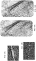
- Figure 13A and 13B are radiographic images of an example clot retrieval device according to aspects of the present invention. Radiopaque material in the distal coil, proximal coil, and markers appear dark in the radiographic images.
- a clot retrieval device can be sized to accommodate a variety of treatment needs.
- Dimension such as overall length L1 of the outer expandable member, working length L2 of the device, diameter D1 of the outer expandable member D1, and diameter D2 of the inner expandable member can be measured as indicated in Figures 2A through 2C and 7A through 7C .
- the outer expandable member when freely expanded, can have an overall length L1 about 34 mm, a working length L2 of about 22 mm, and a diameter D1 of about 5 mm.
- the inner expandable member tubular body diameter D2 can measure less than the outer expandable member diameter, preferably about 1mm and more preferably about 1.22 mm.
- the example device can be suitable for treating blood vessels having a diameter between about 1.5 mm and about 5 mm.
- the outer expandable member of the example device preferably includes a proximal body segment, exactly one middle body segment, and a distal body segment similar to the proximal body segment 126, middle body segment 127, and distal body segment 128 of the device 100 illustrated in Figures 1A through 5C .
- the outer expandable member when freely expanded, can have an overall length L1 about 49 mm, a working length L2 of about 37 mm, and a diameter D1 of about 5 mm.
- the inner expandable member tubular body diameter D2 can measure less than the outer expandable member diameter, preferably about 1mm and more preferably about 1.22 mm.
- the example device can be suitable for treating blood vessels having a diameter between about 1.5 mm and about 5 mm.
- the outer expandable member of the example device preferably includes a proximal body segment, exactly three middle body segment, and a distal body segment similar to the proximal body segment 226, middle body segments 227, and distal body segment 228 of the device 200 illustrated in Figures 6A through 10C .
- the outer expandable member when freely expanded, can have an overall length L1 about 57 mm, a working length L2 of about 45 mm, and a diameter D1 of about 6.5 mm.
- the inner expandable member tubular body diameter D2 can measure less than the outer expandable member diameter, preferably about 1mm and more preferably about 1.22 mm. Configured as such, the example device can be suitable for treating blood vessels having a diameter between about 1.5 mm and about 6.5 mm.
- the outer expandable member of the example device preferably includes a proximal body segment, exactly three middle body segment, and a distal body segment similar to the proximal body segment 226, middle body segments 227, and distal body segment 228 of the device 200 illustrated in Figures 6A through 10C .
- a clot retrieval device can be dimensioned such that markers on body segments (e.g. markers 121, 221 on body segments 126, 127, 128, 226, 227, 228 illustrated herein) illustrated herein can be separated in the longitudinal direction (in the direction of the longitudinal axis A-A) from one or more markers on an adjacent body segment by about 10 mm when the clot retrieval device is collapsed for delivery across a clot and can be separated by about 8 mm in the longitudinal direction when the clot retrieval device is freely expanded.
- markers on body segments e.g. markers 121, 221 on body segments 126, 127, 128, 226, 227, 228 illustrated herein
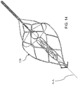
- Figure 14 illustrates an alternative distal portion of an example clot retrieval device described in greater detail in a U.S. Non-Provisional Patent Application titled "A CLOT RETRIEVAL DEVICE FOR REMOVING CLOT FROM A BLOOD VESSEL” filed concurrently herewith and incorporated by reference as if set forth in its entirety herein.
- a clot retrieval device can have alternative geometries suitable for clot retrieval devices.
- the clot retrieval device can include a distal portion configured as illustrated in Figure 14 .
- the outer expandable member can include a distal body portion configured similar to the distal body portion 328 illustrated in Figure 14 .
- the distal portion of the clot retrieval device need not be configured to capture clot fragments and can for instance can have large cell openings or be completely open. Further, in some examples, the clot retrieval device need not include an inner body.
- a "patient” or “subject” can be a human or any animal. It should be appreciated that an animal can be a variety of any applicable type, including, but not limited to, mammal, veterinarian animal, livestock animal or pet-type animal, etc. As an example, the animal can be a laboratory animal specifically selected to have certain characteristics similar to a human (e.g., rat, dog, pig, monkey, or the like).
- the terms “about” or “approximately” for any numerical values or ranges indicate a suitable dimensional tolerance that allows the part or collection of components to function for its intended purpose as described herein. More specifically, “about” or “approximately” may refer to the range of values ⁇ 20% of the recited value, e.g. "about 90%” may refer to the range of values from 71% to 99%. Ranges can be expressed herein as from “about” or “approximately” one particular value and/or to "about” or “approximately” another particular value. When such a range is expressed, other exemplary embodiments include from the one particular value and/or to the other particular value.
Landscapes
- Health & Medical Sciences (AREA)
- Surgery (AREA)
- Life Sciences & Earth Sciences (AREA)
- Heart & Thoracic Surgery (AREA)
- Molecular Biology (AREA)
- Veterinary Medicine (AREA)
- Engineering & Computer Science (AREA)
- Biomedical Technology (AREA)
- Nuclear Medicine, Radiotherapy & Molecular Imaging (AREA)
- Medical Informatics (AREA)
- Public Health (AREA)
- Animal Behavior & Ethology (AREA)
- General Health & Medical Sciences (AREA)
- Vascular Medicine (AREA)
- Orthopedic Medicine & Surgery (AREA)
- Pathology (AREA)
- Oral & Maxillofacial Surgery (AREA)
- Media Introduction/Drainage Providing Device (AREA)
- Surgical Instruments (AREA)
Abstract
Description
- This invention relates to devices and methods of removing acute blockages from blood vessels. More specifically, the invention relates to removing obstructions from cerebral arteries in patients suffering acute ischemic stroke (AIS), from pulmonary arteries in patients suffering from pulmonary embolism (PE), from coronary native or graft vessels in patients suffering from myocardial infarction (MI), and from other peripheral arterial and venous vessels in which a clot or other obstruction (e.g. misplaced device, migrated device, large emboli, etc.) is causing an occlusion.
- Thromboembolism occurs when part or all of a thrombus breaks away from the blood vessel wall. This clot (now called an embolus) is then carried in the direction of blood flow. An ischemic stroke may result if the clot lodges in the cerebral vasculature. A pulmonary embolism may result if the clot originates in the venous system or in the right side of the heart and lodges in a pulmonary artery or branch thereof. Clots may also develop and block vessels locally without being released in the form of an embolus-this mechanism is common in the formation of coronary blockages.
- There are a number of access challenges that make it difficult to deliver treatment devices to a clot or other obstruction. In cases where access involves navigating the aortic arch (such as coronary or cerebral blockages) the configuration of the arch in some patients makes it difficult to position a guide catheter. These difficult arch configurations are classified as either type 2 or type 3 aortic arches with type 3 arches presenting the most difficulty. The tortuosity challenge is even more severe in the arteries approaching the brain. For example, it is not unusual at the distal end of the internal carotid artery that the device will have to navigate a vessel segment with a 180° bend, a 90° bend and a 360° bend in quick succession over a few centimeters of vessel. In the case of pulmonary embolisms, access may be gained through the venous system and then through the right atrium and ventricle of the heart. The right ventricular outflow tract and pulmonary arteries are delicate vessels that can easily be damaged by inflexible or high profile devices. For these reasons it is desirable that an obstruction retrieval device be compatible with a delivery catheter having a low profile and high flexibility.
- The vasculature in the area in which the clot may be lodged is often fragile and delicate. For example, neurovascular vessels are more fragile than similarly sized vessels in other parts of the body and are in a soft tissue bed. Excessive tensile forces applied on these vessels could result in perforations and hemorrhage. Pulmonary vessels are larger than those of the cerebral vasculature, but are also delicate in nature, particularly more superior vessels.
- The clot may comprise any of a range of morphologies and consistencies. Long strands of softer clot material may tend to lodge at bifurcations or trifurcations, resulting in multiple vessels being simultaneously occluded over significant lengths. More mature and organized clot material is likely to be less compressible than softer fresher clot, and under the action of blood pressure it may distend the compliant vessel in which it is lodged.
- The clots may not only range in shape and consistency, but also may vary greatly in length, even in any one given area of the anatomy. For example, clots occluding the middle cerebral artery of an ischemic stroke patient may range from just a few millimeters to several centimeters in length.
- Stent-like clot retrievers are being increasingly used to remove clot and other obstructions from cerebral vessels of acute stroke patients. These are self-expanding devices, similar in appearance to a stent attached to the end of a long shaft and are advanced through a microcatheter and deployed across clot obstructions in order to trap and retrieve them. They rely on a pinning mechanism to grab the clot by trapping the clot between the self-expanding stent-like body and the vessel wall.
- Typically, a stent-like clot retriever relies on its outward radial force (RF) to retain its grip on the clot. If the RF is too low the stent-like clot retriever will lose its grip on the clot, but if the RF is too high the stent-like clot retriever may damage the vessel wall and may require too much force to withdraw. Because clots vary in morphology across patients, RF required to grip the clot also varies. Because blood vessel fragility and geometry also varies across patients, RF required to reduce the risk of vessel trauma also varies.
- In some treatments, some known stent-like clot retriever designs can lose their grip on a clot when withdrawn proximally around a bend in a tortuous vessel. This typically occurs because the struts of the stent-like clot retriever are placed in tension when it is retracted. This tension is due to friction between the device and the blood vessel and is increased if an additional load is applied load such as that provided by a clot. In a bend the struts on the outside of the bend are placed in higher tension than those on the inside. In order to attain the lowest possible energy state, the outside surface of the stent moves towards the inside surface of the bend, which reduces the tension in the struts, but also reduces the expanded diameter of the stent-like clot retriever.
- Some treatments rely on pinning the clot between the stent-like clot retriever and the vessel wall and thus may not restrain the clot effectively when passing a branch vessel or when passing into a vessel that is larger than the fully expanded diameter of the stent-like clot retriever. Pinning the clot between the stent-like clot retriever and the vessel wall in order to remove it from the vessel also results in high shear forces against the side of the clot as it is removed, potentially releasing fragments of the clot. If these fragments are not retained by the device, they may be released leading to further blockages in the distal vasculature.
- In some treatments, the stent-like clot retriever may be shorter than the clot itself. A device that is shorter than the clot is unlikely to be able to restore flow through the occluded area upon deployment, and thus the pressure gradient across the clot remains a significant impediment to its removal. Simply making such a device longer would likely render it difficult to track through tortuous anatomies and could be traumatic to the vasculature, taking more force to withdraw and potentially getting stuck and requiring surgery to remove.
- For many reasons including some or all of the above limitations it is often necessary for a physician to make multiple passes with a clot retrieval device in order to fully remove an obstructive clot. However, each time a clot retrieval device is withdrawn the access to the target site is lost. The initial access steps of placing the large bore catheter do not need to be repeated as it remains in place after the initial clot retrieval attempt. Only the steps of accessing the clot site after the large bore catheter has been placed need to be repeated. Thus, it is necessary to re-advance a guidewire and microcatheter to access and re-cross the clot, and then remove the guidewire and advance the clot retrieval device through the microcatheter. Navigating the guidewire and microcatheter to the clot can take a considerable amount of time, especially if the vessels are tortuous. This additional time and device manipulation all adds to the risks to which the patient is exposed.
- Examples disclosed herein generally include a clot retrieval device having an inner expandable member and an outer expandable member, each formed from respective strut frameworks such that the outer expandable member has larger cell openings than the inner expandable member. The outer expandable member can have multiple discontinuous body segments spaced apart in relation to a longitudinal axis of the device. Adjacent discontinuous body segments can be joined by a pair of tapered connecting arms that are able to bend with a small radius of curvature compared to the body segments. This small radius of curvature can have a range of values depending on the tortuosity of the vasculature the device is expanded in. It will approximately equal 0 mm when the device is in a straight vessel and will approximately equal 0.5 mm when the device is in a vessel with a 180-degree bend. Some or all of the body segments can include radiopaque markers positioned to illustrate a circumference of the respective body segment and slightly staggered in relation to a longitudinal axis of the device such that the markers nest when the device is collapsed for delivery.
- An example clot retrieval device has a collapsed configuration and an expanded configuration. The clot retrieval device is configured to remove clot from a blood vessel. The clot retrieval device has an inner expandable member and an outer expandable member. The inner expandable member has a first framework of struts and the outer expandable member has a second framework of struts. The second framework at least partially radially surrounds the inner expandable member.
- Closed cells of the second framework of the outer expandable member can be larger than closed cells of the first framework of the inner expandable member.
- The outer expandable member can have a first and a second body segment connected by two connecting arms, wherein the first body segment is positioned in a proximal direction in relation the second body segment. Each of the two connecting arms respectively can have a tapered shape that is wider where the arm is near the first, proximal body segment and narrower where the arm is near the second, distal body segment. As shown in
FIG. 1B andFIG. 4C , approximate values for the labelled dimensions are as follows; the height 'H' has a value of 0.075 mm, the strut width 'W1' has a value of 0.16 mm, the strut width 'W2' has a value of 0.08 mm and the strut width 'W3' has a value of 0.20 mm. Hence, the approximate percentage change in width between 'W1' and 'W2' is a decrease of 50% and the approximate percentage change in width between 'W2' and 'W3' is an increase of 60%. The outer expandable member can have additional body segments connected to the first and/or second body segment by additional connecting arms. - The outer expandable member can have at least two inlet mouths in the second framework including a pair of inlet mouths between the first and second body segments. Each of the two inlet mouths between the first and second body segment can have a respective opening bounded by the first body segment, the second body segment, and the two connecting arms.
- The first body segment can have at least two pairs of struts each terminating in a respective distal apex and forming a proximal boundary of a respective inlet mouth of the two inlet mouths.
- The two connecting arms between the first and second body segments of the outer expandable member can extend substantially parallel to a longitudinal axis of the device.
- The two connecting arms between the first and second body segments of the outer expandable member can be positioned approximately 180° from each other about a circumference of the outer expandable member.
- The first body segment and the second body segment can be connected to each other solely via the two connecting arms.
- Each of the two connecting arms can be configured to bend with a curvature having a radius smaller than a radius of curvature of a majority of struts of the first body segment and the second body segment as the clot retrieval device is pulled proximally through a tubular vasculature comprising a bend of about 180°.
- The outer expandable member can have three or more body segments each shaped substantially similarly to the first body segment and the second body segment. The outer expandable member can include pairs of tapered connecting arms such that each respective pair of tapered connecting arms joins longitudinally adjacent body segments of the three or more body segments. The tapered connecting arms can be shaped and oriented similarly to the connecting arms between the first and second body segments.
- One or both of the first and second body segments can respectively include four or more radiopaque markers positioned around a circumference of the respective body segment. When the clot retrieval device is in the collapsed configuration, each of the radiopaque markers can be offset from adjacent radiopaque markers of the four or more radiopaque markers. The markers can be offset from adjacent radiopaque makers in relation to a longitudinal axis of the device. When the clot retrieval device is in the collapsed configuration, alternating radiopaque markers of the four or more radiopaque markers can be aligned in a plane orthogonal to the longitudinal axis.
- The first body segment can include a first set of four or more radiopaque markers. The second body segment can include a second set of four or more radiopaque markers. When the clot retrieval device is in the expanded configuration, the first and second sets of four or more radiopaque markers are spaced approximately 8 millimeters apart, measured in the direction of the longitudinal axis. When the clot retrieval device is in the collapsed configuration, the first and second sets of four or more radiopaque markers are spaced approximately 10 millimeters apart, measured in the direction of the longitudinal axis.
- Each of the four or more radiopaque markers can include radiopaque material positioned in an eyelet.
- At least two of the four or more radiopaque markers can be aligned, in the direction of the longitudinal axis, with a respective connecting arm of the two connecting arms.
- Another example clot retrieval device can have a collapsed configuration and an expanded configuration. The clot retrieval device is configured to remove clot from a blood vessel. Structures and functionality of this example clot retrieval device are combinable with structures and features of the previous example clot retrieval device.
- The example clot retrieval device includes an inner expandable member having a first framework of struts and an outer expandable member having a second framework of struts. The second framework of struts can form closed cells larger than closed cells of the first framework of inner expandable member. The second framework can at least partially radially surround the first framework of the inner expandable member.
- The example clot retrieval device can include four or more radiopaque markers affixed to the second framework of struts and positioned to indicate a circumference of the outer expandable member. The radiopaque markers can be further positioned such that when the clot retrieval device is in the collapsed configuration, each of the radiopaque markers is offset, in relation to a longitudinal axis of the device to respective circumferentially adjacent radiopaque markers.
- The outer expandable member can include discontinuous body segments spaced apart from each other in the direction of the longitudinal axis. The radiopaque markers can be positioned to indicate a circumference of a body segment of the discontinuous body segments.
- The example clot retrieval device can include a first body segment and a second body segment, wherein the first body segment is positioned in a proximal direction in relation the second body segment. The outer expandable member can include two connecting arms joining the first body segment to the second body segment. Each of the two connecting arms can respectively have a tapered shape that is wider near the proximal, first body segment and narrower near the distal, second body segment.
- At least two of the four or more radiopaque markers can be aligned, in the direction of the longitudinal axis, with a respective connecting arm of the two connecting arms.
- The outer expandable member can include two inlet mouths in the second framework. Each of the two inlet mouths can include a respective opening bounded by the first body segment, the second body segment, and the two connecting arms.
- The first body segment can include the four or more radiopaque markers forming a first set of markers, and the second body segment can include a second set of four or more radiopaque markers positioned to indicate a circumference of the second body segment. The second set of radiopaque markers can be positioned such that when the clot retrieval device is in the collapsed configuration, each of the radiopaque markers of the second set is offset, in relation to a longitudinal axis of the device to respective adjacent radiopaque markers of the second set. Markers in the first set of radiopaque markers can be similarly offset.
- The two connecting arms can be positioned approximately 180° from each other about a circumference of the outer expandable member.
-
-
Figure 1A shows an isometric view of an example clot retrieval device according to aspects of the present invention. -
Figure 1B shows a close-up of a portion of the clot retrieval device illustrated inFigure 1A , the portion including a tapered strut according to aspects of the present invention. -
Figure 2A shows a plan view of a first side of the clot retrieval device illustrated inFigure 1A . -
Figure 2B shows the view clot retrieval device as illustrated inFigure 2A having an inner expandable member of the clot retrieval device removed from the illustration. -
Figure 2C shows the view of the clot retrieval device as illustrated inFigure 2A having an outer expandable member of the clot retrieval device removed from the illustration. -
Figure 3A shows a plan view of a second side of the clot retrieval device illustrated inFigure 1A , the second side viewed at 90° from the first side view illustrated inFigure 2A . -
Figure 3B shows the view clot retrieval device as illustrated inFigure 3A having the inner expandable member of the clot retrieval device removed from the illustration. -
Figure 3C shows the view of the clot retrieval device as illustrated inFigure 3A having the outer expandable member of the clot retrieval device removed from the illustration. -
Figure 4A shows a linear view of the outer expandable member of the clot retrieval device cut along a centerline indicated inFigures 2B and3B and flattened. -
Figure 4B shows a close-up of a portion of the outer expandable member of the clot retrieval device as indicated inFigure 4A . -
Figure 4C shows a close-up of a portion of the outer expandable member of the clot retrieval device as indicated inFigure 4B . -
Figure 5A shows a plan view of a distal end of the clot retrieval device illustrated inFigure 1A . -
Figure 5B shows the view clot retrieval device as illustrated inFigure 5A having the inner expandable member of the clot retrieval device removed from the illustration. -
Figure 5C shows the view of the clot retrieval device as illustrated inFigure 5A having the outer expandable member of the clot retrieval device removed from the illustration. -
Figure 6A shows an isometric view of another example clot retrieval device according to aspects of the present invention. -
Figure 6B shows a close-up of a portion of the clot retrieval device illustrated inFigure 6A , the portion including a tapered strut according to aspects of the present invention. -
Figure 7A shows a plan view of a first side of the clot retrieval device illustrated inFigure 6A . -
Figure 7B shows the view clot retrieval device as illustrated inFigure 7A having an inner expandable member of the clot retrieval device removed from the illustration. -
Figure 7C shows the view of the clot retrieval device as illustrated inFigure 7A having an outer expandable member of the clot retrieval device removed from the illustration. -
Figure 8A shows a plan view of a second side of the clot retrieval device illustrated inFigure 6A , the second side viewed at 90° from the first side view illustrated inFigure 7A . -
Figure 8B shows the view clot retrieval device as illustrated inFigure 8A having the inner expandable member of the clot retrieval device removed from the illustration. -
Figure 8C shows the view of the clot retrieval device as illustrated inFigure 8A having the outer expandable member of the clot retrieval device removed from the illustration. -
Figure 9 shows a linear view of the outer expandable member of the clot retrieval device cut along a centerline indicated inFigures 7B and8B and flattened. -
Figure 10A shows a plan view of a distal end of the clot retrieval device illustrated inFigure 6A . -
Figure 10B shows the view clot retrieval device as illustrated inFigure 10A having the inner expandable member of the clot retrieval device removed from the illustration. -
Figure 10C shows the view of the clot retrieval device as illustrated inFigure 10A having the outer expandable member of the clot retrieval device removed from the illustration. -
Figure 11A shows an example outer expandable member traversing a lumen having a 360° bend according to aspects of the present invention. -
Figure 11B shows a close-up of a portion of the outer expandable member as indicated inFigure 11A . -
Figure 12A shows an illustration of a portion of an example expandable member having a radiopaque marker according to aspects of the present invention. -
Figure 12B shows a side view of the portion of the expandable member illustrated inFigure 12A . -
Figure 13A and 13B are radiographic images of an example clot retrieval device according to aspects of the present invention. -
Figure 14 shows an illustration of an alternative distal portion of an example clot retrieval device according to aspects of the present invention. - Specific embodiments of the present invention are now described in detail with reference to the figures, wherein identical reference numbers indicate identical or functionality similar elements. The terms "distal" or "proximal" are used in the following description with respect to a position or direction relative to the treating physician. "Distal" or "distally" are a position distant from or in a direction away from the physician. "Proximal" or "proximally" or "proximate" are a position near or in a direction toward the physician.
- Accessing cerebral, coronary and pulmonary vessels involves the use of a number of commercially available products and conventional procedural steps. Access products such as guidewires, guide catheters, angiographic catheters and microcatheters are described elsewhere and are regularly used in catheter lab procedures. It is assumed in the descriptions below that these products and methods are employed in conjunction with the device and methods of this invention and do not need to be described in detail.
- The following detailed description is merely exemplary in nature and is not intended to limit the invention or the application and uses of the invention. Although the description of the invention is in many cases in the context of treatment of intracranial arteries, the invention may also be used in other body passageways as previously described.
-
Figure 1A shows a distal portion of an exampleclot retrieval device 100 in an expanded configuration. Theclot retrieval device 100 generally extends to define a longitudinal axis A-A and has adistal coil 108 at its distal end, an outerexpandable member 102 and an innerexpandable member 103 extending proximally and coaxially from thedistal coil 108, and aproximal coil 104 extending proximally from the outerexpandable member 102 and the innerexpandable member 103. Thedevice 100 can include additional features such as anelongate shaft 106, asleeve 105, andindicator bands 107. Thedevice 100 can include a distal junction orcollar 109 joining thedistal coil 108 to the outerexpandable member 102 and the innerexpandable member 103. Thedevice 100 can include a proximal junction orcollar 112 joining theproximal coil 104 to the outerexpandable member 102 and the innerexpandable member 103. Thejunctions expandable layers U.S. 10,390,850 -
Figure 1B shows a close-up of a portion of the clot retrieval device illustrated inFigure 1A , the portion including a tapered strut according to aspects of the present invention. -
Figure 2A shows a plan view of a first side of theclot retrieval device 100.Figure 2B shows the viewclot retrieval device 100 as illustrated inFigure 2A having the innerexpandable member 103 removed for the purpose of illustration.Figure 2C shows the view of theclot retrieval device 100 as illustrated inFigure 2A having the outerexpandable member 102 removed for the purpose of illustration.Figure 3A shows a plan view of a second side of theclot retrieval device 100, the second side viewed at 90° from the first side view illustrated inFigure 2A .Figure 3B shows the viewclot retrieval device 100 as illustrated inFigure 3A having the innerexpandable member 103 removed for the purpose of illustration.Figure 3C shows the view of theclot retrieval device 100 as illustrated inFigure 3A having the outerexpandable member 102 removed for the purpose of illustration.Figure 4A shows a linear view of the outerexpandable member 102 cut along a line B-B indicated inFigures 2B and3B and flattened.Figure 4B shows a close-up of a portion of the outerexpandable member 102 as indicated inFigure 4A .Figure 4C shows a close-up of a portion of the outerexpandable member 102 as indicated inFigure 4B .Figure 5A shows a plan view of a distal end of theclot retrieval device 100.Figure 5B shows the view of theclot retrieval device 100 as illustrated inFigure 5A having the innerexpandable member 103 removed for the purpose of illustration.Figure 5C shows the view of theclot retrieval device 100 as illustrated inFigure 5A having the outerexpandable member 102 removed for the purpose of illustration. - As described in greater detail in relation to
Figures 1B and4C , the outerexpandable member 102 can include taperedstruts body segments expandable member 102 to facilitate withdraw of thedevice 100 from tortuous vascular when an obstruction is at least partially confined by the outerexpandable member 102. Additionally, or alternatively, the tapered struts 129, 130 are shaped to promote apposition of the outerexpandable member 102 circumferentially to blood vessel walls as thedevice 100 is withdrawn through tortuous vasculature when an obstruction is at least partially confined by the outerexpandable member 102. - As described in greater detail in relation to
Figures 4A and 4B , the outerexpandable member 103 can include staggered radiopaque markers positioned to facilitate visualization of thedevice 100 during treatment while also maintaining a small profile collapsed configuration of the outerexpandable member 102 to facilitate traverse of thecollapsed device 100 across a clot or other obstruction. - Referring collectively to
Figures 1A through 5C , the outerexpandable member 102 and innerexpandable member 103 are collapsible into a restraining sheath (e.g. microcatheter) sized to traverse a clot or other obstruction. The outerexpandable member 102 and innerexpandable member 103 are each configured to self-expand upon release from the restraining sheath. In the expanded configuration, thedevice 100 can facilitate clot retrieval, flow restoration, and/or fragmentation protection. - Both the inner and outer
expandable members - The inner
expandable member 103 is preferably configured to expand to a lesser diameter D2 than that of the smallest vessel in which it is intended to be used. This diameter D2 is typically less than 50% that of the diameter D1 of the outerexpandable member 102 and may be as low as 20% or less of the outer member diameter D1. - A distal scaffolding zone can incorporate strut elements from the framework of the outer and/or inner
expandable members portion 110 of the innerexpandable member 103 and adistal portion 128 of the outerexpandable member 102. The strut geometry of the distal scaffolding zone can be shaped as illustrated herein, or as described in relation to compatible stent-like clot retrievers, including but not limited to as disclosed inU.S. 10,390,850 - In each of the expanded configuration and the collapsed configuration, the inner
expandable member 103 and outer expandable members define respective tubular bodies. Preferably the tubular bodies are coaxial about the longitudinal axis A-A. Thedevice 100 includes areception space 111 within the outerexpandable member 102 and outside the innerexpandable member 103 when the inner and outexpandable members device 100 andreception space 111 are sized, shaped, and otherwise configured to allow a clot to become at least partially confined within the reception space during a clot removal treatment. The interior of the innerexpandable member 103 when expanded is configured to provide a flow path through which blood can flow when thedevice 100 is expanded through a clot. - During a clot removal treatment, the length of the outer
expandable member 102 can be about as long as the length of the occlusive clot or longer to remove many of the degrees of freedom of movement freedom otherwise available to the clot. Theouter member 102 includesinlet openings 222 sized, shaped, another otherwise configured to provide the primary freedom of movement available to the clot and so the expansion of theouter member 102 urges the clot into thereception space 111. Theouter member 102 hasmultiple inlet mouths 122 to accept the clot. In thisway inlet mouths 122 allow portions of the clot to enterreception space 111 of theouter member 102, and thus allow the clot to be retrieved without being excessively compressed. This is advantageous because the inventors have discovered that compression of clot causes it to dehydrate, which in turn increases the frictional properties of the clot, and increases its stiffness, all of which makes the clot more difficult to disengage and remove from the vessel. This compression can be avoided if the clot migrates inward through the scaffolding of theouter member 102 as the scaffolding migrates outward towards the vessel wall. - The
inlet mouths 122 can further allow theouter member 102, when retracted, to apply a force to the clot in a direction substantially parallel to the direction in which the clot is to be pulled from the vessel (i.e. substantially parallel to the central axis of the vessel). This means that the outward radial force applied to the vasculature may be kept to a minimum, which in turn means that the action of theclot retrieval device 100 on the clot does not serve to increase the force required to dislodge the clot from the vessel, thus protecting delicate cerebral vessels from harmful radial and tensile forces. - The outer
expandable member 102 includesproximal struts 120 connected at their proximal ends to theproximal collar 112 and at their distal ends to aproximal body segment 126. The proximal struts 120 can have a tapered profile or be otherwise configured to provide a gradual stiffness transition from theshaft 106 to the tubular body of the outerexpandable member 102. - The
proximal body segment 126 is connected to amiddle body segment 127 by two connectingarms 129, which run from aproximal junction 139 to adistal junction 140. Themiddle body segment 127 is in turn connected to adistal body segment 128 by two connectingarms 130, which run from aproximal junction 141 to adistal junction 142. The region between the middle anddistal body segments inlet mouths 122 through which clot may pass and enter thereception space 111 defined by the region between the inner andouter members - As illustrated in greater detail in
Figures 1B and4C , each of the connectingarms 129 can have a tapered profile with a width that tapers from a wider dimension W1 at the respectiveproximal junction distal junction distal junction arms distal struts 170. The connectingarms expandable member 102. - In one example, as shown in
FIG. 1B andFIG. 4C , approximate values for the labelled dimensions are as follows; the height H has a value of about 0.075 mm, the proximal strut width W1 has a value of about 0.16 mm, the distal strut width W2 has a value of about 0.08 mm and the bifurcation strut width W3 has a value of about 0.20 mm. Hence, the approximate percentage change in width between the proximal width W1 and the distal width W2 is a decrease of 50% and the approximate percentage change in width between the distal width W2 and the bifurcation width W3 is an increase of 60%. - The tapered shape of the connecting
arms arms expandable member 102. (See radius r as illustrated inFigure 11B .) - The connecting
arms 129 between theproximal body segment 126 and themiddle body segment 127 of the outerexpandable member 102 can be substantially aligned with the connectingarms 130 between the middle anddistal body segments body segments arms 129 between theproximal body segment 126 and themiddle body segment 127 can be aligned at an angle, such as 90° to the connectingarms 130 between the middle anddistal body segments - As illustrated in greater detail in
Figures 2B and3B , theproximal body segment 126 includes interconnected struts, with certain struts such asstrut 143 terminating in adistal apex 133 with no distal connecting elements, and other struts such as 144 terminating injunction points middle body segment 127 includes interconnected struts, with certain struts such asstrut 147 terminating in adistal apex 134 with no distal connecting elements, and other struts such asstrut 148 terminating injunction points 171. - One or more of the
body segments oval markers distal body segments markers 125 on thedistal body segment 128 can be positioned to indicate to the user the position of thedistal body segment 128 and therefore distal portion of thedevice 100 to aid in accuracy of deployment of thedevice 100. Thedistal body segment 128 can include asingle marker 125 to indicate the position of thedistal body segment 128, or multiple markers to indicate a circumference of thedistal body segment 128. Each of the proximal andmiddle body segments oval markers 121 positioned circumferentially around therespective body segment respective body segments middle body segments markers 121 positioned approximately equidistant around a circumference C1 of the outerexpandable member 102. -
Figures 4A and 4B illustrate the outerexpandable member 102 cut along the line B-B as indicated inFigures 2B and3B , laid flat, and collapsed so to a height C2 corresponding to a circumference of the outerexpandable member 102 when thedevice 100 is constrained by a microcatheter or sheath. As illustrated in greater detail inFigure 4B , themarkers 121 on each of theproximal body segment 126 and themiddle body segment 127 are staggered, offset in the direction of the longitudinal axis A-A (i.e. positioned at different distances from the proximal collar 112) to facilitate collapse of the height C (circumference) of the outerexpandable member 102. Each of therespective markers 121 connect to anelongated segment 172 which is shaped to nest theadjacent markers 121 between a junction (e.g. junction 141) and the respectiveconnected marker 121. Theelongated segments 172 andmarkers 121 are positioned in an alternating fashion circumferentially. - The struts in the
body segments e.g. junction 145 andjunction 150 and other similarly shaped junctions) do not align at the same distance from the proximal collar. During loading or re-sheathing, a higher force is generally required to load a junction (crown) than a strut into the sheath, therefore if multiple crowns are loaded at the same time the user may notice an increase in loading force. By offsetting the crowns by makingalternative struts - The distal end of the
distal body segment 128 includes struts forming a tapered shape terminating at thedistal junction point 109, thus defining a closed end distal to theouter member 102. Thedistal body segment 128 is viewed from the distal end of thedevice 100 in a planar view inFigure 5A with the innerexpandable member 103 removed inFigure 5B for the purposes of illustration and the outerexpandable member 102 removed inFigure 5C for the purposes of illustration. The distal end of thedistal body segment 128 can include a distal framework as illustrated herein, or an alternative distal framework usable with a stent-like clot retriever device. The tapered portion of thedistal body segment 128 can be shaped and otherwise configured to prevent egress of clot or clot fragments that have entered thereception space 111 between the inner andouter members distal struts 110 of theinner member 103 act as an additional three dimensional filter in combination with the closed end of theouter member 102 to further prevent the egress of clot or clot fragments. In certain embodiments this distal section may comprise fiber attachment points such as eyelets or other fiber attachment features and fibers may be connected to the distal section at these attachment points to create a distal net. - As illustrated in greater detail in
Figures 2C ,3C , and5C , the innerexpandable member 103 is configured to self-expand upon release from a restraining sheath (such as a microcatheter) to a diameter D2 that is larger than the expanded diameter D1 of the outerexpandable member 102 and smaller than a diameter of a blood vessel that thedevice 100 is configured to treat. The innertubular member 103 includes a scaffolding that is denser, having smaller openings, compared to the outerexpandable member 102. The innertubular member 103 is configured so as to provide a flow lumen through thedevice 100 to facilitate the immediate restoration of blood flow past the clot upon deployment. Additionally, or alternatively, the innertubular member 103 is configured to scaffold said flow lumen through the clot to prevent the liberation of fragments which might otherwise lodge in the distal vasculature. The innertubular member 103 includes connectedstruts 131 that may contact a clot when initially deployed in a target vessel within the clot. The contact of thestruts 131 of the innertubular member 103 with the clot can provide additional grip and assists in the initial dislodgement of the clot from the vessel when the device is retracted. - Inner
expandable member 103 includes a generally cylindrical section ofinterconnected struts 131, which is connected at its proximal end by a strut 138 (or multiple struts) to theproximal junction 112. The distal end of the innerexpandable member 103 includes of an expansile section formed from expandedstruts 110 which have a diameter greater than the diameter D2 of the body section of the innertubular member 103. These expanded struts 110 are connected to acoil section 118 which in this embodiment is laser cut from the tubing that the innerexpandable member 103 is also cut from during processing. - The
shaft 106 can include a tapered wire shaft, and may be made of stainless steel, MP35N, Nitinol or other material of a suitably high modulus and tensile strength.Shaft 106 may haveindicator bands 107 on the shaft to indicate to the user when the distal end of the device is approaching the end of the microcatheter during insertion. These bands are positioned so that as they approach a microcatheter hub or hemostasis valve they indicate the distal tip of the device is approaching the end of the microcatheter. These indicator bands can be formed by printing or removing or masking areas of shaft coating so that they are visually differentiated from the remainder of the shaft. Theindicator bands 107 can additionally be recessed below the surface of theshaft 106 to give tactile feedback to the user as they approach the microcatheter. - The
proximal coil 104 can extend from a distal portion of theshaft 106. Theproximal coil 104 coil can be metallic and may be formed from stainless steel or from a more radiopaque material such as platinum or gold for example or an alloy of such a material. Additionally, or alternatively, the coil may be coated with a low friction material or have a polymeric jacket positioned on the outer surface of the coil. Adjacent to this coil 104 asleeve 105 may be positioned onshaft 106. Thissleeve 105 can include polymeric material and may be positioned over the tapered section of the shaft. Thesleeve 105 may be rendered radiopaque through the addition of a filler material such as tungsten or barium sulphate. Thesleeve 105 andshaft 106 may be coated with a material to reduce friction and thrombogenicity. The coating may consist of a polymer, a low friction lubricant such as silicon, a hydrophilic or a hydrophobic coating. This coating may also be applied to theouter member 102 and innertubular member 103. - The
outer member 102 and the innertubular member 103 can joined at theproximal junction 112 and thedistal junction 109 during assembly. To minimize tension within themembers outer member 102 can be substantially the same as the length of theinner member 103 in the freely expanded configuration and the collapsed, loaded configuration. The expanded struts 110 of the innertubular member 103 elongate during loading so that the lengths of the inner and outer members are equal when fully loaded in a microcatheter. Length differentials between theinner member 103 and theouter member 102 can still occur when the device is deployed in a small vessel or during the loading or deployment process. Thecoil 118 at the distal end of the innertubular member 103 can accommodate minor length differentials by stretching without applying significant tensile or compressive forces to the device. In another embodiment thiscoil 118 could be formed separately to the innertubular member 103 and then be assembled to it. Thecoil 118 can be formed from a stainless steel material, a polymer or from a more radiopaque metal such as gold or platinum or an alloy of such a material. Thecoil 118 can also be replaced with a longitudinal length of an elastic material such as a low modulus polymer or elastomer. - In other embodiments the
inner member 103 may not be connected to the distal end of theouter member 102 at all or may be constrained within theouter member 102 without being fixedly attached. In other embodiments theinner member 103 may have a non-cylindrical cross-section, may be non-uniform in diameter, and may have tailored strut patterns to provide regions of differing radial force or flexibility. -
Figure 6A shows an isometric view of another exampleclot retrieval device 200. Compared to thedevice 100 illustrated inFigures 1A through 5D , the outerexpandable member 202 of theclot retrieval device 200 illustrated inFigure 6A includes multiplemiddle body segments 227 rather than a singlemiddle body segment 127. At least the proximal 226 and themiddle body segments 227 respectively include interconnected struts, with certain struts terminating in adistal apex 233 with no distal connecting elements, and other struts terminating injunction points. Thedevice 200 illustrated inFigure 6A includes threemiddle body segments 227. According to the present invention, a clot retrieval device including features described and illustrated herein can include one, two, three, four, five, or more middle body segments. Thedevice 200 includes an innerexpandable member 203 elongated to accommodate the additionalmiddle body segments 227 of the outerexpandable member 202. - The
device 200 can include areception space 211 between the outerexpandable member 202 and innerexpandable member 203 configured similarly to thereception space 111 of thedevice 100 illustrated inFigures 1A through 5C . - The
device 200 can further include aproximal coil 204,distal coil 208,distal junction 209, andproximal junction 212 structured similarly as correspondingcomponents Figures 1A through 5D . Thedevice 200 can further include a sleeve, shaft, and indicator bands structured similar ascorresponding components Figure 1A . -
Figure 6B shows a close-up of a portion of theclot retrieval device 200 illustrated inFigure 6A . The portion includes a tapered connectingarm 230. The connectingarm 230 can be shaped as illustrated and described in relation to tapered connectingarms device 100 illustrated inFigures 1A through 5C . Connectingarms 230 can join the proximal, middle, anddistal body segments arms device 100 illustrated inFigures 1A through 5C . -
Figure 7A shows a plan view of a first side of theclot retrieval device 200.Figure 7B shows the viewclot retrieval device 200 as illustrated inFigure 7A having the innerexpandable member 203 removed for the purpose of illustration.Figure 7C shows the view of theclot retrieval device 200 as illustrated inFigure 7A having the outerexpandable member 202 removed for the purpose of illustration. - The outer
expandable member 202 of thedevice 200 can include a proximal struts 220 and aproximal body segment 226 structured similarly to theproximal struts 120 andproximal body segment 126 of thedevice 100 illustrated inFigures 1A through 5C . The outerexpandable member 202 can include adistal body segment 228 structured similarly to thedistal body segment 128 of thedevice 100 illustrated inFigures 1A through 5C . The outerexpandable member 202 can includeradiopaque markers markers device 100 illustrated inFigures 1A through 5C . The outerexpandable member 202 can includeinlet mouths 222 configured similarly toinlet mouths 122 of thedevice 100 illustrated inFigures 1A through 5C . - The inner
expandable member 203 can include distal crown struts 210, interconnecting struts 231 in a tubular body portion, and proximal connectingstruts 234 similar tocorresponding struts device 100 illustrated inFigures 1A through 5C . The innerexpandable member 203 can be connected to aninner coil 218 configured similar to theinner coil 118 of thedevice 100 illustrated inFigures 1A through 5C . -
Figure 8A shows a plan view of a second side of the clot retrieval device illustrated inFigure 6A , the second side viewed at 90° from the first side view illustrated inFigure 7A .Figure 8B shows the viewclot retrieval device 200 as illustrated inFigure 8A having the innerexpandable member 203 removed for the purpose of illustration.Figure 8C shows the view of theclot retrieval device 200 as illustrated inFigure 8A having the outerexpandable member 202 removed for the purpose of illustration. -
Figure 9 shows a linear view of the outerexpandable member 202 cut along a centerline B-B indicated inFigures 7B and8B and flattened. A portion of the outerexpandable member 202 as indicated inFigure 9 can be configured as illustrated inFigure 4B and further as illustrated inFigure 4C . For instance,radiopaque markers 221 can be staggered as illustrated in greater detail inFigure 4B . Connectingarms 230 can be tapered and otherwise configured asarms 129 illustrated in greater detail inFigures 4B and4C . Struts and joints of the outerexpandable member 202 can be shaped and otherwise configured to correspond to joints and struts 144, 145, 146, 147, 150, 151 illustrated inFigures 4B and4C . -
Figure 10A shows a plan view of a distal end of theclot retrieval device 200.Figure 10B shows the viewclot retrieval device 200 as illustrated inFigure 10A having the innerexpandable member 203 removed for the purpose of illustration.Figure 10C shows the view of theclot retrieval device 200 as illustrated inFigure 10A having the outerexpandable member 202 removed for the purpose of illustration. -
Figure 11A shows an example outerexpandable member 302 traversing a lumen having a 360° bend with a radius of curvature rB at the apex of the bend. Because the outerexpandable member 302 closely follows the bend of lumen, the outer expandable member has a radius of curvature that is approximately equal to the radius of curvature rB of the lumen.Figure 11B shows a close-up of a portion of the outerexpandable member 302 as indicated inFigure 11A . The outerexpandable member 302 includes tapered connectingarms 330 betweenbody segments 327 configured similarly to the connectingarms devices Figures 1A through 10C . As shown in greater detail inFigure 11B , the outerexpandable member 302 has a curvature with a radius rA at a narrow area of the connectingarm 330 that is smaller than the overall radius of curvature rB of the outerexpandable member 302 around the bend the lumen. In other words, the connectingarm 330 provides a bending point for the outerexpandable member 302. The flexibility of the connectingarm 330 can allow thebody segments 327 to extend juxtaposed to a lumen (e.g. the illustrated lumen and/or a blood vessel lumen) to a greater extent than a similarly structured outer expandable member having less flexible connecting arms. In one example, the outerexpandable member 302 can be configured to bend with a curvature having a radius rA at the narrow area of the connectingarm 330 of approximately 0.5 millimeters (mm) or greater including 0.6 mm, 0.7 mm, 0.8 mm, 0.9 mm, and 1.0 mm. -
Figure 12A shows an illustration of a portion of an example expandable member having a radiopaque marker.Figure 12B shows a side view of the portion of the expandable member illustrated inFigure 12A . Some or all of themarkers Figures 12A and 12B . -
Figure 13A and 13B are radiographic images of an example clot retrieval device according to aspects of the present invention. Radiopaque material in the distal coil, proximal coil, and markers appear dark in the radiographic images. - A clot retrieval device according to the teachings herein can be sized to accommodate a variety of treatment needs. Dimension such as overall length L1 of the outer expandable member, working length L2 of the device, diameter D1 of the outer expandable member D1, and diameter D2 of the inner expandable member can be measured as indicated in
Figures 2A through 2C and7A through 7C . - In one example device, when freely expanded, the outer expandable member can have an overall length L1 about 34 mm, a working length L2 of about 22 mm, and a diameter D1 of about 5 mm. The inner expandable member tubular body diameter D2 can measure less than the outer expandable member diameter, preferably about 1mm and more preferably about 1.22 mm. Configured as such, the example device can be suitable for treating blood vessels having a diameter between about 1.5 mm and about 5 mm. The outer expandable member of the example device preferably includes a proximal body segment, exactly one middle body segment, and a distal body segment similar to the
proximal body segment 126,middle body segment 127, anddistal body segment 128 of thedevice 100 illustrated inFigures 1A through 5C . - In another example device, when freely expanded, the outer expandable member can have an overall length L1 about 49 mm, a working length L2 of about 37 mm, and a diameter D1 of about 5 mm. The inner expandable member tubular body diameter D2 can measure less than the outer expandable member diameter, preferably about 1mm and more preferably about 1.22 mm. Configured as such, the example device can be suitable for treating blood vessels having a diameter between about 1.5 mm and about 5 mm. The outer expandable member of the example device preferably includes a proximal body segment, exactly three middle body segment, and a distal body segment similar to the
proximal body segment 226,middle body segments 227, anddistal body segment 228 of thedevice 200 illustrated inFigures 6A through 10C . - In another example device, when freely expanded, the outer expandable member can have an overall length L1 about 57 mm, a working length L2 of about 45 mm, and a diameter D1 of about 6.5 mm. The inner expandable member tubular body diameter D2 can measure less than the outer expandable member diameter, preferably about 1mm and more preferably about 1.22 mm. Configured as such, the example device can be suitable for treating blood vessels having a diameter between about 1.5 mm and about 6.5 mm. The outer expandable member of the example device preferably includes a proximal body segment, exactly three middle body segment, and a distal body segment similar to the
proximal body segment 226,middle body segments 227, anddistal body segment 228 of thedevice 200 illustrated inFigures 6A through 10C . - In some examples, a clot retrieval device according to the teachings herein can be dimensioned such that markers on body segments (
e.g. markers body segments -
Figure 14 illustrates an alternative distal portion of an example clot retrieval device described in greater detail in a U.S. Non-Provisional Patent Application titled "A CLOT RETRIEVAL DEVICE FOR REMOVING CLOT FROM A BLOOD VESSEL" filed concurrently herewith and incorporated by reference as if set forth in its entirety herein. - In some examples, a clot retrieval device according to the teachings herein can have alternative geometries suitable for clot retrieval devices. For instance, the clot retrieval device can include a distal portion configured as illustrated in
Figure 14 . The outer expandable member can include a distal body portion configured similar to thedistal body portion 328 illustrated inFigure 14 . Alternatively, the distal portion of the clot retrieval device need not be configured to capture clot fragments and can for instance can have large cell openings or be completely open. Further, in some examples, the clot retrieval device need not include an inner body. - As discussed herein, a "patient" or "subject" can be a human or any animal. It should be appreciated that an animal can be a variety of any applicable type, including, but not limited to, mammal, veterinarian animal, livestock animal or pet-type animal, etc. As an example, the animal can be a laboratory animal specifically selected to have certain characteristics similar to a human (e.g., rat, dog, pig, monkey, or the like).
- As used herein, the terms "about" or "approximately" for any numerical values or ranges indicate a suitable dimensional tolerance that allows the part or collection of components to function for its intended purpose as described herein. More specifically, "about" or "approximately" may refer to the range of values ±20% of the recited value, e.g. "about 90%" may refer to the range of values from 71% to 99%. Ranges can be expressed herein as from "about" or "approximately" one particular value and/or to "about" or "approximately" another particular value. When such a range is expressed, other exemplary embodiments include from the one particular value and/or to the other particular value.
- By "comprising" or "containing" or "including" is meant that at least the named compound, element, particle, or method step is present in the composition or article or method, but does not exclude the presence of other compounds, materials, particles, method steps, even if the other such compounds, material, particles, method steps have the same function as what is named.
- It must also be noted that, as used in the specification and the appended claims, the singular forms "a," "an," and "the" include plural referents unless the context clearly dictates otherwise.
- In describing examples, terminology is resorted to for the sake of clarity. It is intended that each term contemplates its broadest meaning as understood by those skilled in the pertinent art and includes all technical equivalents that operate in a similar manner to accomplish a similar purpose. It is also to be understood that the mention of one or more steps of a method does not preclude the presence of additional method steps or intervening method steps between those steps expressly identified. Steps of a method can be performed in a different order than those described herein without departing from the scope of the disclosed technology. Similarly, it is also to be understood that the mention of one or more components in a device or system does not preclude the presence of additional components or intervening components between those components expressly identified.
- The descriptions contained herein are examples of the disclosure and are not intended in any way to limit the scope of the disclosure. While particular examples of the present disclosure are described, various modifications to devices and methods can be made without departing from the scope and spirit of the disclosure. For example, while the examples described herein refer to particular components, the disclosure includes other examples utilizing various combinations of components to achieve a described functionality, utilizing alternative materials to achieve a described functionality, combining components from the various examples, combining components from the various example with known components, etc. The disclosure contemplates substitutions of component parts illustrated herein with other well-known and commercially-available products. The scope of the claims which follow are intended to include such modifications as apparent to those having skill in the pertinent art as understood according to the teachings herein.
-
- 1. A clot retrieval device comprising a collapsed configuration and an expanded configuration and configured to remove clot from a blood vessel, the device comprising:
- an inner expandable member comprising a first framework of struts; and
- an outer expandable member comprising:
- a second framework of struts that form closed cells larger than closed cells of the inner expandable member and that at least partially radially surround the inner expandable member, and
- four or more radiopaque markers affixed to the second framework of struts and positioned to indicate a circumference of the outer expandable member and further positioned such that when the clot retrieval device is in the collapsed configuration, each of the radiopaque markers is offset, in relation to a longitudinal axis of the device to respective circumferentially adjacent radiopaque markers of the four or more radiopaque markers.
- 2. The clot retrieval device of
aspect 1,
wherein the outer expandable member comprises discontinuous body segments spaced apart from each other in the direction of the longitudinal axis, and
wherein the four or more radiopaque markers are positioned to indicate a circumference of a body segment of the discontinuous body segments. - 3. The clot retrieval device of aspect 2,
wherein the body segments comprise a first body segment and a second body segment, the first body segment being positioned in a proximal direction in relation the second body segment,
wherein the outer expandable member comprises two connecting arms joining the first body segment to the second body segment, and
wherein each of the two connecting arms respectively comprises a tapered shape being wider approximate the first body segment and narrower approximate the second body segment. - 4. The clot retrieval device of aspect 3, wherein at least two of the four or more radiopaque markers are aligned, in the direction of the longitudinal axis, with a respective connecting arm of the two connecting arms.
- 5. The clot retrieval device of aspect 3, wherein the outer expandable member comprises two inlet mouths in the second framework, each of the two inlet mouths comprising a respective opening bounded by the first body segment, the second body segment, and the two connecting arms.
- 6. The clot retrieval device of aspect 3,
wherein the first body segment comprises the four or more radiopaque markers forming a first set of markers, and
wherein the second body segment comprises a second set of four or more radiopaque markers positioned to indicate a circumference of the second body segment and further positioned such that when the clot retrieval device is in the collapsed configuration, each of the radiopaque markers of the second set is offset, in relation to a longitudinal axis of the device to respective adjacent radiopaque markers of the second set. - 7. The clot retrieval device of aspect 3,
wherein the two connecting arms are positioned approximately 180° from each other about a circumference of the outer expandable member.
Claims (13)
- A clot retrieval device comprising a collapsed configuration and an expanded configuration and being configured to remove clot from a blood vessel, the device comprising:an inner expandable member comprising a first framework of struts; andan outer expandable member comprising a second framework of struts that form closed cells larger than closed cells of the inner expandable member and that at least partially radially surround the inner expandable member,the outer expandable member comprising a first and a second body segment connected by two connecting arms,the first body segment being positioned in a proximal direction in relation the second body segment, andeach of the two connecting arms respectively comprising a tapered shape being wider approximate the first body segment and narrower approximate the second body segment.
- The clot retrieval device of claim 1, wherein the outer expandable member comprises two inlet mouths in the second framework, each of the two inlet mouths comprising a respective opening bounded by the first body segment, the second body segment, and the two connecting arms.
- The clot retrieval device of claim 2, wherein the first body segment comprises two pairs of struts each terminating in a respective distal apex and forming a proximal boundary of a respective inlet mouth of the two inlet mouths.
- The clot retrieval device of claim 1, wherein the two connecting arms extend substantially parallel to a longitudinal axis of the device.
- The clot retrieval device of claim 1, wherein the two connecting arms are positioned approximately 180° from each other about a circumference of the outer expandable member.
- The clot retrieval device of claim 1, wherein the first body segment and the second body segment are connected to each other solely via the two connecting arms.
- The clot retrieval device of claim 1, wherein each of the two connecting arms is configured to bend with a curvature having a radius smaller than a radius of curvature of a majority of struts of the first body segment and the second body segment as the clot retrieval device is pulled proximally through a tubular vasculature comprising a bend of about 180°. This small radius of curvature can have a range of values depending on the tortuosity of the vasculature the device is expanded in. It will approximately equal 0 mm when the device is in a straight vessel and will approximately equal 0.5 mm when the device is in a vessel with a 180-degree bend.
- The clot retrieval device of claim 1,
wherein the outer expandable member comprises three or more body segments each shaped substantially similarly to the first body segment and the second body segment, and
wherein the outer expandable member comprises pairs of tapered connecting arms such that each respective pair of tapered connecting arms joins longitudinally adjacent body segments of the three or more body segments. - The clot retrieval device of claim 1,
wherein at least one of the first body segment and the second body segment comprises four or more radiopaque markers positioned around a circumference of the respective body segment, and
wherein, when the clot retrieval device is in the collapsed configuration, each of the radiopaque markers is offset, in relation to a longitudinal axis of the device to respective adjacent radiopaque markers of the four or more radiopaque markers. - The clot retrieval device of claim 9, wherein when the clot retrieval device is in the collapsed configuration, alternating radiopaque markers of the four or more radiopaque markers are aligned in a plane orthogonal to the longitudinal axis.
- The clot retrieval device of claim 9,
wherein the first body segment comprises a first set of four or more radiopaque markers,
wherein the second body segment comprises a second set of four or more radiopaque markers,
wherein, when the clot retrieval device is in the expanded configuration, the first and second sets of four or more radiopaque markers are spaced approximately 8 millimeters apart measured in the direction of the longitudinal axis, and
wherein, when the clot retrieval device is in the collapsed configuration, the first and second sets of four or more radiopaque markers are spaced approximately 10 millimeters apart measured in the direction of the longitudinal axis. - The clot retrieval device of claim 9, wherein each of the four or more radiopaque markers comprises radiopaque material positioned in an eyelet.
- The clot retrieval device of claim 9, wherein at least two of the four or more radiopaque markers are aligned, in the direction of the longitudinal axis, with a respective connecting arm of the two connecting arms.
Priority Applications (1)
| Application Number | Priority Date | Filing Date | Title |
|---|---|---|---|
| EP25181713.6A EP4591808A3 (en) | 2020-06-23 | 2021-06-22 | Clot retrieval device with flexible collapsible frame |
Applications Claiming Priority (1)
| Application Number | Priority Date | Filing Date | Title |
|---|---|---|---|
| US16/946,464 US11395669B2 (en) | 2020-06-23 | 2020-06-23 | Clot retrieval device with flexible collapsible frame |
Related Child Applications (1)
| Application Number | Title | Priority Date | Filing Date |
|---|---|---|---|
| EP25181713.6A Division EP4591808A3 (en) | 2020-06-23 | 2021-06-22 | Clot retrieval device with flexible collapsible frame |
Publications (3)
| Publication Number | Publication Date |
|---|---|
| EP3928722A1 true EP3928722A1 (en) | 2021-12-29 |
| EP3928722B1 EP3928722B1 (en) | 2025-06-11 |
| EP3928722C0 EP3928722C0 (en) | 2025-06-11 |
Family
ID=76553577
Family Applications (2)
| Application Number | Title | Priority Date | Filing Date |
|---|---|---|---|
| EP21180773.0A Active EP3928722B1 (en) | 2020-06-23 | 2021-06-22 | Clot retrieval device with flexible collapsible frame |
| EP25181713.6A Pending EP4591808A3 (en) | 2020-06-23 | 2021-06-22 | Clot retrieval device with flexible collapsible frame |
Family Applications After (1)
| Application Number | Title | Priority Date | Filing Date |
|---|---|---|---|
| EP25181713.6A Pending EP4591808A3 (en) | 2020-06-23 | 2021-06-22 | Clot retrieval device with flexible collapsible frame |
Country Status (6)
| Country | Link |
|---|---|
| US (2) | US11395669B2 (en) |
| EP (2) | EP3928722B1 (en) |
| JP (1) | JP7789499B2 (en) |
| KR (1) | KR20210158349A (en) |
| CN (1) | CN113827314B (en) |
| ES (1) | ES3035742T3 (en) |
Families Citing this family (21)
| Publication number | Priority date | Publication date | Assignee | Title |
|---|---|---|---|---|
| US7686825B2 (en) | 2004-03-25 | 2010-03-30 | Hauser David L | Vascular filter device |
| WO2015061365A1 (en) | 2013-10-21 | 2015-04-30 | Inceptus Medical, Llc | Methods and apparatus for treating embolism |
| CN108472052B (en) | 2015-10-23 | 2021-10-01 | 伊纳里医疗公司 | Endovascular treatment of vascular occlusion and related devices, systems and methods |
| CN110312481B (en) | 2016-10-24 | 2023-04-11 | 伊纳里医疗有限公司 | Devices and methods for treating vascular occlusions |
| ES3008609T3 (en) | 2017-09-06 | 2025-03-24 | Inari Medical Inc | Hemostasis valves and methods of use |
| US11154314B2 (en) | 2018-01-26 | 2021-10-26 | Inari Medical, Inc. | Single insertion delivery system for treating embolism and associated systems and methods |
| ES3000010T3 (en) | 2018-08-13 | 2025-02-27 | Inari Medical Inc | System for treating embolism and associated devices and methods |
| CA3157521A1 (en) | 2019-10-16 | 2021-04-22 | Inari Medical, Inc. | Systems, devices, and methods for treating vascular occlusions |
| US12446961B2 (en) | 2020-02-10 | 2025-10-21 | Bolt Medical, Inc. | System and method for pressure monitoring within a catheter system |
| US12702479B2 (en) | 2020-03-09 | 2026-08-11 | Boston Scientific Scimed, Inc. | Laser pulse shaping to enhance conversion efficiency and protect fiber optic delivery system for disruption of vascular calcium |
| US12611253B2 (en) | 2020-03-18 | 2026-04-28 | Boston Scientific Scimed, Inc. | Optical analyzer assembly and method for intravascular lithotripsy device |
| US20210353359A1 (en) | 2020-05-12 | 2021-11-18 | Bolt Medical, Inc. | Active alignment system and method for optimizing optical coupling of multiplexer for laser-driven intravascular lithotripsy device |
| AU2021283979A1 (en) | 2020-06-05 | 2023-01-19 | Stryker Corporation | Recapturable funnel catheters, and associated systems and methods |
| US12672915B2 (en) | 2021-08-24 | 2026-07-07 | Boston Scientific Scimed, Inc. | Connector for multiplexer optical coupling |
| US12364496B2 (en) | 2022-01-11 | 2025-07-22 | Inari Medical, Inc. | Devices for removing clot material from intravascularly implanted devices, and associated systems and methods |
| JP2025503965A (en) | 2022-02-08 | 2025-02-06 | イナリ メディカル, インコーポレイテッド | Clot treatment system with expander locking mechanism and related devices and methods |
| US12533184B2 (en) | 2022-04-02 | 2026-01-27 | Boston Scientific Scimed, Inc. | Optical connector assembly for intravascular lithotripsy device |
| US12653608B2 (en) | 2022-08-07 | 2026-06-16 | Boston Scientific Scimed, Inc. | Optoelectrical connector for intravascular lithotripsy device |
| AU2024207180A1 (en) | 2023-01-09 | 2025-07-17 | Stryker Corporation | Catheter for use with clot treatment systems |
| US12558486B2 (en) | 2023-11-16 | 2026-02-24 | Inari Medical, Inc. | Automatic locking and unlocking vacuum syringes, and associated systems and methods |
| US12465382B1 (en) | 2024-05-10 | 2025-11-11 | Inari Medical, Inc. | Mechanical thrombectomy assemblies with relief features, and associated devices, systems, and methods |
Citations (5)
| Publication number | Priority date | Publication date | Assignee | Title |
|---|---|---|---|---|
| US20140200608A1 (en) * | 2011-03-09 | 2014-07-17 | Neuravi Limited | Clot retrieval device for removing occlusive clot from a blood vessel |
| US20160015402A1 (en) * | 2013-03-14 | 2016-01-21 | Neuravi Limited | Devices and methods for removal of acute blockages from blood vessels |
| CA3006614A1 (en) * | 2015-11-25 | 2017-06-01 | Neuravi Limited | A clot retrieval device for removing occlusive clot from a blood vessel |
| US10390850B2 (en) | 2013-03-14 | 2019-08-27 | Neuravi Limited | Clot retrieval device for removing clot from a blood vessel |
| US20200085444A1 (en) * | 2018-09-13 | 2020-03-19 | Neuravi Limited | Systems and methods of restoring perfusion to a vessel |
Family Cites Families (738)
| Publication number | Priority date | Publication date | Assignee | Title |
|---|---|---|---|---|
| US2828147A (en) | 1954-01-20 | 1958-03-25 | Alfred M Peiffer | Electrical wire clamp |
| US3361460A (en) | 1966-05-02 | 1968-01-02 | Gerhard Jansen | Clamp nut |
| US4455717A (en) | 1982-09-22 | 1984-06-26 | Gray Robert C | Rope clamping device |
| US4611594A (en) | 1984-04-11 | 1986-09-16 | Northwestern University | Medical instrument for containment and removal of calculi |
| IT1176442B (en) | 1984-07-20 | 1987-08-18 | Enrico Dormia | INSTRUMENT FOR THE EXTRACTION OF FOREIGN BODIES FROM THE BODY'S PHYSIOLOGICAL CHANNELS |
| US4793348A (en) | 1986-11-15 | 1988-12-27 | Palmaz Julio C | Balloon expandable vena cava filter to prevent migration of lower extremity venous clots into the pulmonary circulation |
| US4873978A (en) | 1987-12-04 | 1989-10-17 | Robert Ginsburg | Device and method for emboli retrieval |
| US5011488A (en) | 1988-12-07 | 1991-04-30 | Robert Ginsburg | Thrombus extraction system |
| US5084065A (en) | 1989-07-10 | 1992-01-28 | Corvita Corporation | Reinforced graft assembly |
| US5217441A (en) | 1989-08-15 | 1993-06-08 | United States Surgical Corporation | Trocar guide tube positioning device |
| DE8910603U1 (en) | 1989-09-06 | 1989-12-07 | Günther, Rolf W., Prof. Dr. | Device for removing blood clots from arteries and veins |
| US5092839A (en) | 1989-09-29 | 1992-03-03 | Kipperman Robert M | Coronary thrombectomy |
| US5122136A (en) | 1990-03-13 | 1992-06-16 | The Regents Of The University Of California | Endovascular electrolytically detachable guidewire tip for the electroformation of thrombus in arteries, veins, aneurysms, vascular malformations and arteriovenous fistulas |
| DE69102515T2 (en) | 1990-04-02 | 1994-10-20 | Kanji Inoue | DEVICE FOR CLOSING A SHUTTER OPENING BY MEANS OF A NON-OPERATIONAL METHOD. |
| US5171233A (en) | 1990-04-25 | 1992-12-15 | Microvena Corporation | Snare-type probe |
| US5236447A (en) | 1990-06-29 | 1993-08-17 | Nissho Corporation | Artificial tubular organ |
| US5108419A (en) | 1990-08-16 | 1992-04-28 | Evi Corporation | Endovascular filter and method for use thereof |
| US5100423A (en) | 1990-08-21 | 1992-03-31 | Medical Engineering & Development Institute, Inc. | Ablation catheter |
| US5449372A (en) | 1990-10-09 | 1995-09-12 | Scimed Lifesystems, Inc. | Temporary stent and methods for use and manufacture |
| US5163951A (en) | 1990-12-27 | 1992-11-17 | Corvita Corporation | Mesh composite graft |
| WO1992022254A1 (en) | 1991-06-17 | 1992-12-23 | Wilson-Cook Medical, Inc. | Endoscopic extraction device having composite wire construction |
| US5234437A (en) | 1991-12-12 | 1993-08-10 | Target Therapeutics, Inc. | Detachable pusher-vasoocclusion coil assembly with threaded coupling |
| AU674510B2 (en) | 1992-09-23 | 1997-01-02 | Target Therapeutics, Inc. | Medical retrieval device |
| FR2699809B1 (en) | 1992-12-28 | 1995-02-17 | Celsa Lg | Device which can selectively constitute a temporary blood filter. |
| US5538512A (en) | 1993-02-25 | 1996-07-23 | Zenzon; Wendy J. | Lubricious flow directed catheter |
| JPH0795982A (en) | 1993-04-19 | 1995-04-11 | Olympus Optical Co Ltd | Disposable medical devices |
| GB9308893D0 (en) | 1993-04-29 | 1993-06-16 | Special Trustees For The Unite | Apparatus for collecting data |
| US5897567A (en) | 1993-04-29 | 1999-04-27 | Scimed Life Systems, Inc. | Expandable intravascular occlusion material removal devices and methods of use |
| US5855598A (en) | 1993-10-21 | 1999-01-05 | Corvita Corporation | Expandable supportive branched endoluminal grafts |
| US5639278A (en) | 1993-10-21 | 1997-06-17 | Corvita Corporation | Expandable supportive bifurcated endoluminal grafts |
| US5499985A (en) | 1993-11-24 | 1996-03-19 | Orthopaedic Innovations, Inc. | Detachable coupling system for surgical instruments |
| US5387226A (en) | 1994-01-14 | 1995-02-07 | Baxter International Inc. | Rapid exchange catheter |
| US5609627A (en) | 1994-02-09 | 1997-03-11 | Boston Scientific Technology, Inc. | Method for delivering a bifurcated endoluminal prosthesis |
| US5538515A (en) | 1994-03-22 | 1996-07-23 | Sentani Trading Ltd. | Method for making a randomly faded fabric |
| JP3647456B2 (en) | 1994-04-29 | 2005-05-11 | ボストン・サイエンティフィック・コーポレーション | Medical artificial stent and method for producing the same |
| DE69529338T3 (en) | 1994-07-08 | 2007-05-31 | Ev3 Inc., Plymouth | Intravascular filter device |
| US5558652A (en) | 1994-10-06 | 1996-09-24 | B. Braun Medical, Inc. | Introducer with radiopaque marked tip and method of manufacture therefor |
| US5658296A (en) | 1994-11-21 | 1997-08-19 | Boston Scientific Corporation | Method for making surgical retrieval baskets |
| US5709704A (en) | 1994-11-30 | 1998-01-20 | Boston Scientific Corporation | Blood clot filtering |
| US5549626A (en) | 1994-12-23 | 1996-08-27 | New York Society For The Ruptured And Crippled Maintaining The Hospital For Special Surgery | Vena caval filter |
| CA2212084C (en) | 1995-02-02 | 2008-11-18 | Boston Scientific Corporation | Surgical wire basket extractor |
| US6348056B1 (en) | 1999-08-06 | 2002-02-19 | Scimed Life Systems, Inc. | Medical retrieval device with releasable retrieval basket |
| US5645558A (en) | 1995-04-20 | 1997-07-08 | Medical University Of South Carolina | Anatomically shaped vasoocclusive device and method of making the same |
| US5639277A (en) | 1995-04-28 | 1997-06-17 | Target Therapeutics, Inc. | Embolic coils with offset helical and twisted helical shapes |
| US5624461A (en) | 1995-06-06 | 1997-04-29 | Target Therapeutics, Inc. | Three dimensional in-filling vaso-occlusive coils |
| US5713853A (en) | 1995-06-07 | 1998-02-03 | Interventional Innovations Corporation | Methods for treating thrombosis |
| RU2157146C2 (en) | 1995-06-13 | 2000-10-10 | ВИЛЬЯМ КУК Европа, A/S | Device for performing implantation in blood vessels and hollow organs |
| JPH0919438A (en) | 1995-07-04 | 1997-01-21 | Asahi Optical Co Ltd | Basket-type grasping tool for endoscope |
| US6264663B1 (en) | 1995-10-06 | 2001-07-24 | Metamorphic Surgical Devices, Llc | Device for removing solid objects from body canals, cavities and organs including an invertable basket |
| US5779716A (en) | 1995-10-06 | 1998-07-14 | Metamorphic Surgical Devices, Inc. | Device for removing solid objects from body canals, cavities and organs |
| US6168604B1 (en) | 1995-10-06 | 2001-01-02 | Metamorphic Surgical Devices, Llc | Guide wire device for removing solid objects from body canals |
| US5653605A (en) | 1995-10-16 | 1997-08-05 | Woehl; Roger | Locking coupling |
| US5827304A (en) | 1995-11-16 | 1998-10-27 | Applied Medical Resources Corporation | Intraluminal extraction catheter |
| US5769871A (en) | 1995-11-17 | 1998-06-23 | Louisville Laboratories, Inc. | Embolectomy catheter |
| US5665117A (en) | 1995-11-27 | 1997-09-09 | Rhodes; Valentine J. | Endovascular prosthesis with improved sealing means for aneurysmal arterial disease and method of use |
| US5695519A (en) | 1995-11-30 | 1997-12-09 | American Biomed, Inc. | Percutaneous filter for carotid angioplasty |
| EP0955954B1 (en) | 1996-01-05 | 2005-03-16 | Medtronic, Inc. | Expansible endoluminal prostheses |
| US6168622B1 (en) | 1996-01-24 | 2001-01-02 | Microvena Corporation | Method and apparatus for occluding aneurysms |
| US5895398A (en) | 1996-02-02 | 1999-04-20 | The Regents Of The University Of California | Method of using a clot capture coil |
| IL125417A (en) | 1996-02-02 | 2004-03-28 | Transvascular Inc | Apparatus for blocking flow through blood vessels |
| NL1002423C2 (en) | 1996-02-22 | 1997-08-25 | Cordis Europ | Temporary filter catheter. |
| US5853422A (en) | 1996-03-22 | 1998-12-29 | Scimed Life Systems, Inc. | Apparatus and method for closing a septal defect |
| US6254571B1 (en) | 1996-04-18 | 2001-07-03 | Applied Medical Resources Corporation | Remote clot management |
| US5935139A (en) | 1996-05-03 | 1999-08-10 | Boston Scientific Corporation | System for immobilizing or manipulating an object in a tract |
| US6096053A (en) | 1996-05-03 | 2000-08-01 | Scimed Life Systems, Inc. | Medical retrieval basket |
| US6022336A (en) | 1996-05-20 | 2000-02-08 | Percusurge, Inc. | Catheter system for emboli containment |
| US5769884A (en) | 1996-06-27 | 1998-06-23 | Cordis Corporation | Controlled porosity endovascular implant |
| US6066158A (en) | 1996-07-25 | 2000-05-23 | Target Therapeutics, Inc. | Mechanical clot encasing and removal wire |
| US6325819B1 (en) | 1996-08-19 | 2001-12-04 | Cook Incorporated | Endovascular prosthetic device, an endovascular graft prothesis with such a device, and a method for repairing an abdominal aortic aneurysm |
| US5931509A (en) | 1996-11-19 | 1999-08-03 | Proprietary Technology, Inc. | Connection verification and secondary latch device |
| US5827321A (en) | 1997-02-07 | 1998-10-27 | Cornerstone Devices, Inc. | Non-Foreshortening intraluminal prosthesis |
| US5893869A (en) | 1997-02-19 | 1999-04-13 | University Of Iowa Research Foundation | Retrievable inferior vena cava filter system and method for use thereof |
| US7094249B1 (en) | 1997-03-06 | 2006-08-22 | Boston Scientific Scimed, Inc. | Distal protection device and method |
| AU6688398A (en) | 1997-03-06 | 1998-09-22 | Percusurge, Inc. | Intravascular aspiration system |
| US5814064A (en) | 1997-03-06 | 1998-09-29 | Scimed Life Systems, Inc. | Distal protection device |
| US5911734A (en) | 1997-05-08 | 1999-06-15 | Embol-X, Inc. | Percutaneous catheter and guidewire having filter and medical device deployment capabilities |
| US5947995A (en) | 1997-06-06 | 1999-09-07 | Samuels; Shaun Lawrence Wilkie | Method and apparatus for removing blood clots and other objects |
| US5904698A (en) | 1997-06-10 | 1999-05-18 | Applied Medical Resources Corporation | Surgical shaving device for use within body conduits |
| US5919126A (en) | 1997-07-07 | 1999-07-06 | Implant Sciences Corporation | Coronary stent with a radioactive, radiopaque coating |
| US5911725A (en) | 1997-08-22 | 1999-06-15 | Boury; Harb N. | Intraluminal retrieval catheter |
| US6395014B1 (en) | 1997-09-26 | 2002-05-28 | John A. Macoviak | Cerebral embolic protection assembly and associated methods |
| US6361545B1 (en) | 1997-09-26 | 2002-03-26 | Cardeon Corporation | Perfusion filter catheter |
| US6066149A (en) | 1997-09-30 | 2000-05-23 | Target Therapeutics, Inc. | Mechanical clot treatment device with distal filter |
| US6099534A (en) | 1997-10-01 | 2000-08-08 | Scimed Life Systems, Inc. | Releasable basket |
| US6174318B1 (en) | 1998-04-23 | 2001-01-16 | Scimed Life Systems, Inc. | Basket with one or more moveable legs |
| US5908435A (en) | 1997-10-23 | 1999-06-01 | Samuels; Shaun L. W. | Expandable lumen device and method of use |
| US5911702A (en) | 1997-11-06 | 1999-06-15 | Heartport, Inc. | Methods and devices for cannulating a patient's blood vessel |
| US7491216B2 (en) | 1997-11-07 | 2009-02-17 | Salviac Limited | Filter element with retractable guidewire tip |
| CA2450927C (en) | 1997-11-07 | 2007-11-06 | Salviac Limited | An embolic protection device |
| US6238412B1 (en) | 1997-11-12 | 2001-05-29 | William Dubrul | Biological passageway occlusion removal |
| US6221006B1 (en) | 1998-02-10 | 2001-04-24 | Artemis Medical Inc. | Entrapping apparatus and method for use |
| US20100030256A1 (en) | 1997-11-12 | 2010-02-04 | Genesis Technologies Llc | Medical Devices and Methods |
| AU754067B2 (en) | 1997-11-14 | 2002-11-07 | Boston Scientific Limited | Multi-sheath delivery catheter |
| JP3075355B2 (en) | 1998-02-05 | 2000-08-14 | オリンパス光学工業株式会社 | Basket type grasping forceps |
| US6602265B2 (en) | 1998-02-10 | 2003-08-05 | Artemis Medical, Inc. | Tissue separation medical device and method |
| US6488701B1 (en) | 1998-03-31 | 2002-12-03 | Medtronic Ave, Inc. | Stent-graft assembly with thin-walled graft component and method of manufacture |
| US6960222B2 (en) | 1998-03-13 | 2005-11-01 | Gore Enterprise Holdins, Inc. | Catheter having a funnel-shaped occlusion balloon of uniform thickness and methods of manufacture |
| DE69929182T2 (en) | 1998-04-23 | 2006-09-21 | Boston Scientific Ltd., St. Michael | MEDICAL DEVICE FOR RECOVERING SEPARATE ORGAN PARTS BY MEANS OF LEGS |
| US6511492B1 (en) | 1998-05-01 | 2003-01-28 | Microvention, Inc. | Embolectomy catheters and methods for treating stroke and other small vessel thromboembolic disorders |
| US6099559A (en) | 1998-05-28 | 2000-08-08 | Medtronic Ave, Inc. | Endoluminal support assembly with capped ends |
| IL124958A0 (en) | 1998-06-16 | 1999-01-26 | Yodfat Ofer | Implantable blood filtering device |
| US6241746B1 (en) | 1998-06-29 | 2001-06-05 | Cordis Corporation | Vascular filter convertible to a stent and method |
| US6656218B1 (en) | 1998-07-24 | 2003-12-02 | Micrus Corporation | Intravascular flow modifier and reinforcement device |
| US6165194A (en) | 1998-07-24 | 2000-12-26 | Micrus Corporation | Intravascular flow modifier and reinforcement device |
| US6093199A (en) | 1998-08-05 | 2000-07-25 | Endovascular Technologies, Inc. | Intra-luminal device for treatment of body cavities and lumens and method of use |
| US6156064A (en) | 1998-08-14 | 2000-12-05 | Schneider (Usa) Inc | Stent-graft-membrane and method of making the same |
| US6143022A (en) | 1998-08-24 | 2000-11-07 | Medtronic Ave, Inc. | Stent-graft assembly with dual configuration graft component and method of manufacture |
| US20010049554A1 (en) | 1998-11-18 | 2001-12-06 | Carlos E. Ruiz | Endovascular prosthesis and method of making |
| US6102932A (en) | 1998-12-15 | 2000-08-15 | Micrus Corporation | Intravascular device push wire delivery system |
| US6165199A (en) | 1999-01-12 | 2000-12-26 | Coaxia, Inc. | Medical device for removing thromboembolic material from cerebral arteries and methods of use |
| US6355057B1 (en) | 1999-01-14 | 2002-03-12 | Medtronic, Inc. | Staggered endoluminal stent |
| US6161547A (en) | 1999-01-15 | 2000-12-19 | Coaxia, Inc. | Medical device for flow augmentation in patients with occlusive cerebrovascular disease and methods of use |
| AU774924B2 (en) | 1999-01-22 | 2004-07-15 | W.L. Gore & Associates, Inc. | Covered endoprosthesis and delivery system |
| US7018401B1 (en) | 1999-02-01 | 2006-03-28 | Board Of Regents, The University Of Texas System | Woven intravascular devices and methods for making the same and apparatus for delivery of the same |
| US20020138094A1 (en) | 1999-02-12 | 2002-09-26 | Thomas Borillo | Vascular filter system |
| US6231597B1 (en) | 1999-02-16 | 2001-05-15 | Mark E. Deem | Apparatus and methods for selectively stenting a portion of a vessel wall |
| US20020169474A1 (en) | 1999-03-08 | 2002-11-14 | Microvena Corporation | Minimally invasive medical device deployment and retrieval system |
| US6428558B1 (en) | 1999-03-10 | 2002-08-06 | Cordis Corporation | Aneurysm embolization device |
| US6673089B1 (en) | 1999-03-11 | 2004-01-06 | Mindguard Ltd. | Implantable stroke treating device |
| US6632236B2 (en) | 1999-03-12 | 2003-10-14 | Arteria Medical Science, Inc. | Catheter having radially expandable main body |
| US6245012B1 (en) | 1999-03-19 | 2001-06-12 | Nmt Medical, Inc. | Free standing filter |
| US6893450B2 (en) | 1999-03-26 | 2005-05-17 | Cook Urological Incorporated | Minimally-invasive medical retrieval device |
| CA2305033A1 (en) | 1999-04-12 | 2000-10-12 | Osram Sylvania Inc. | Moisture insensitive electroluminescent phosphor |
| US6746475B1 (en) | 1999-04-15 | 2004-06-08 | Scimed Life Systems, Inc. | Stent with variable stiffness |
| AU3844499A (en) | 1999-05-07 | 2000-11-21 | Salviac Limited | Improved filter element for embolic protection device |
| US6964672B2 (en) | 1999-05-07 | 2005-11-15 | Salviac Limited | Support frame for an embolic protection device |
| GB2365356A (en) | 1999-05-07 | 2002-02-20 | Salviac Ltd | An embolic protection device |
| US20020058911A1 (en) | 1999-05-07 | 2002-05-16 | Paul Gilson | Support frame for an embolic protection device |
| US6918921B2 (en) | 1999-05-07 | 2005-07-19 | Salviac Limited | Support frame for an embolic protection device |
| US6585756B1 (en) | 1999-05-14 | 2003-07-01 | Ernst P. Strecker | Implantable lumen prosthesis |
| US6350271B1 (en) | 1999-05-17 | 2002-02-26 | Micrus Corporation | Clot retrieval device |
| US6375668B1 (en) | 1999-06-02 | 2002-04-23 | Hanson S. Gifford | Devices and methods for treating vascular malformations |
| US6458139B1 (en) | 1999-06-21 | 2002-10-01 | Endovascular Technologies, Inc. | Filter/emboli extractor for use in variable sized blood vessels |
| US6203561B1 (en) | 1999-07-30 | 2001-03-20 | Incept Llc | Integrated vascular device having thrombectomy element and vascular filter and methods of use |
| US7306618B2 (en) | 1999-07-30 | 2007-12-11 | Incept Llc | Vascular device for emboli and thrombi removal and methods of use |
| US6530939B1 (en) | 1999-07-30 | 2003-03-11 | Incept, Llc | Vascular device having articulation region and methods of use |
| US6179861B1 (en) | 1999-07-30 | 2001-01-30 | Incept Llc | Vascular device having one or more articulation regions and methods of use |
| US20020026211A1 (en) | 1999-12-23 | 2002-02-28 | Farhad Khosravi | Vascular device having emboli and thrombus removal element and methods of use |
| US6544279B1 (en) | 2000-08-09 | 2003-04-08 | Incept, Llc | Vascular device for emboli, thrombus and foreign body removal and methods of use |
| US6214026B1 (en) | 1999-07-30 | 2001-04-10 | Incept Llc | Delivery system for a vascular device with articulation region |
| US6616679B1 (en) | 1999-07-30 | 2003-09-09 | Incept, Llc | Rapid exchange vascular device for emboli and thrombus removal and methods of use |
| US6346116B1 (en) | 1999-08-03 | 2002-02-12 | Medtronic Ave, Inc. | Distal protection device |
| US6245087B1 (en) | 1999-08-03 | 2001-06-12 | Embol-X, Inc. | Variable expansion frame system for deploying medical devices and methods of use |
| US6251122B1 (en) | 1999-09-02 | 2001-06-26 | Scimed Life Systems, Inc. | Intravascular filter retrieval device and method |
| US6146404A (en) | 1999-09-03 | 2000-11-14 | Scimed Life Systems, Inc. | Removable thrombus filter |
| US6315778B1 (en) | 1999-09-10 | 2001-11-13 | C. R. Bard, Inc. | Apparatus for creating a continuous annular lesion |
| US6454775B1 (en) | 1999-12-06 | 2002-09-24 | Bacchus Vascular Inc. | Systems and methods for clot disruption and retrieval |
| US6325815B1 (en) | 1999-09-21 | 2001-12-04 | Microvena Corporation | Temporary vascular filter |
| US6939361B1 (en) | 1999-09-22 | 2005-09-06 | Nmt Medical, Inc. | Guidewire for a free standing intervascular device having an integral stop mechanism |
| US6660013B2 (en) | 1999-10-05 | 2003-12-09 | Omnisonics Medical Technologies, Inc. | Apparatus for removing plaque from blood vessels using ultrasonic energy |
| US6375670B1 (en) | 1999-10-07 | 2002-04-23 | Prodesco, Inc. | Intraluminal filter |
| US6364895B1 (en) | 1999-10-07 | 2002-04-02 | Prodesco, Inc. | Intraluminal filter |
| US8632590B2 (en) | 1999-10-20 | 2014-01-21 | Anulex Technologies, Inc. | Apparatus and methods for the treatment of the intervertebral disc |
| US8414543B2 (en) | 1999-10-22 | 2013-04-09 | Rex Medical, L.P. | Rotational thrombectomy wire with blocking device |
| US6425909B1 (en) | 1999-11-04 | 2002-07-30 | Concentric Medical, Inc. | Methods and devices for filtering fluid flow through a body structure |
| US6575997B1 (en) | 1999-12-23 | 2003-06-10 | Endovascular Technologies, Inc. | Embolic basket |
| US6402771B1 (en) | 1999-12-23 | 2002-06-11 | Guidant Endovascular Solutions | Snare |
| US6660021B1 (en) | 1999-12-23 | 2003-12-09 | Advanced Cardiovascular Systems, Inc. | Intravascular device and system |
| US9113936B2 (en) | 1999-12-23 | 2015-08-25 | Abbott Laboratories | Snare |
| US6290710B1 (en) | 1999-12-29 | 2001-09-18 | Advanced Cardiovascular Systems, Inc. | Embolic protection device |
| US6383206B1 (en) | 1999-12-30 | 2002-05-07 | Advanced Cardiovascular Systems, Inc. | Embolic protection system and method including filtering elements |
| DE10000137A1 (en) | 2000-01-04 | 2001-07-12 | Pfm Prod Fuer Die Med Ag | Implantate for closing defect apertures in human or animal bodies, bearing structure of which can be reversed from secondary to primary form by elastic force |
| US6663613B1 (en) | 2000-01-25 | 2003-12-16 | Bacchus Vascular, Inc. | System and methods for clot dissolution |
| US6540768B1 (en) | 2000-02-09 | 2003-04-01 | Cordis Corporation | Vascular filter system |
| US6391037B1 (en) | 2000-03-02 | 2002-05-21 | Prodesco, Inc. | Bag for use in the intravascular treatment of saccular aneurysms |
| DE60126585T2 (en) | 2000-03-10 | 2007-12-06 | Anthony T. Bakersfield Don Michael | Device for the prevention of vascular embolism |
| US6695865B2 (en) | 2000-03-20 | 2004-02-24 | Advanced Bio Prosthetic Surfaces, Ltd. | Embolic protection device |
| US6514273B1 (en) | 2000-03-22 | 2003-02-04 | Endovascular Technologies, Inc. | Device for removal of thrombus through physiological adhesion |
| US6632241B1 (en) | 2000-03-22 | 2003-10-14 | Endovascular Technologies, Inc. | Self-expanding, pseudo-braided intravascular device |
| GB2369575A (en) | 2000-04-20 | 2002-06-05 | Salviac Ltd | An embolic protection system |
| US6592616B1 (en) | 2000-04-28 | 2003-07-15 | Advanced Cardiovascular Systems, Inc. | System and device for minimizing embolic risk during an interventional procedure |
| JP3838326B2 (en) | 2000-04-28 | 2006-10-25 | トヨタ自動車株式会社 | Vehicle deceleration control device |
| ATE270862T1 (en) | 2000-05-09 | 2004-07-15 | Endoart Sa | VASCULAR IMPLANT WITH A CENTRAL DEFLECTOR |
| US6334864B1 (en) | 2000-05-17 | 2002-01-01 | Aga Medical Corp. | Alignment member for delivering a non-symmetric device with a predefined orientation |
| US6602271B2 (en) | 2000-05-24 | 2003-08-05 | Medtronic Ave, Inc. | Collapsible blood filter with optimal braid geometry |
| AUPQ831500A0 (en) | 2000-06-22 | 2000-07-13 | White, Geoffrey H. | Method and apparatus for performing percutaneous thromboembolectomies |
| DE60126084T2 (en) | 2000-06-23 | 2007-08-09 | Salviac Ltd. | FILTER ELEMENT FOR AN EMULSION PROTECTION DEVICE |
| US6565591B2 (en) | 2000-06-23 | 2003-05-20 | Salviac Limited | Medical device |
| US6824545B2 (en) | 2000-06-29 | 2004-11-30 | Concentric Medical, Inc. | Systems, methods and devices for removing obstructions from a blood vessel |
| US20070208371A1 (en) | 2000-06-29 | 2007-09-06 | Concentric Medical, Inc. | Devices and methods for removing obstructions from a patient and methods for making obstruction removing devices |
| US7727242B2 (en) | 2000-06-29 | 2010-06-01 | Concentric Medical, Inc. | Systems, methods and devices for removing obstructions from a blood vessel |
| US6730104B1 (en) | 2000-06-29 | 2004-05-04 | Concentric Medical, Inc. | Methods and devices for removing an obstruction from a blood vessel |
| US7727243B2 (en) | 2000-06-29 | 2010-06-01 | Concentric Medical., Inc. | Systems, methods and devices for removing obstructions from a blood vessel |
| US7285126B2 (en) | 2000-06-29 | 2007-10-23 | Concentric Medical, Inc. | Systems, methods and devices for removing obstructions from a blood vessel |
| US20050288686A1 (en) | 2000-06-29 | 2005-12-29 | Concentric Medical, Inc., A Delaware Corporation | Systems, methods and devices for removing obstructions from a blood vessel |
| US7766921B2 (en) | 2000-06-29 | 2010-08-03 | Concentric Medical, Inc. | Systems, methods and devices for removing obstructions from a blood vessel |
| US20040073243A1 (en) | 2000-06-29 | 2004-04-15 | Concentric Medical, Inc., A Delaware Corporation | Systems, methods and devices for removing obstructions from a blood vessel |
| US8298257B2 (en) | 2000-06-29 | 2012-10-30 | Concentric Medical, Inc. | Systems, methods and devices for removing obstructions from a blood vessel |
| US6663650B2 (en) | 2000-06-29 | 2003-12-16 | Concentric Medical, Inc. | Systems, methods and devices for removing obstructions from a blood vessel |
| CA2411699A1 (en) | 2000-06-29 | 2002-01-10 | Ivan Sepetka | Systems, methods and devices for removing obstructions from a blood vessel |
| AU2001273088A1 (en) | 2000-06-30 | 2002-01-30 | Viacor Incorporated | Intravascular filter with debris entrapment mechanism |
| US6485501B1 (en) | 2000-08-11 | 2002-11-26 | Cordis Corporation | Vascular filter system with guidewire and capture mechanism |
| KR100418132B1 (en) | 2000-09-09 | 2004-02-11 | 주식회사 3지테크놀러지 | Handle structure to open-closing apparatus for window |
| US6537294B1 (en) | 2000-10-17 | 2003-03-25 | Advanced Cardiovascular Systems, Inc. | Delivery systems for embolic filter devices |
| US6589265B1 (en) | 2000-10-31 | 2003-07-08 | Endovascular Technologies, Inc. | Intrasaccular embolic device |
| US6602272B2 (en) | 2000-11-02 | 2003-08-05 | Advanced Cardiovascular Systems, Inc. | Devices configured from heat shaped, strain hardened nickel-titanium |
| US6740094B2 (en) | 2000-11-06 | 2004-05-25 | The Regents Of The University Of California | Shape memory polymer actuator and catheter |
| US7314483B2 (en) | 2000-11-16 | 2008-01-01 | Cordis Corp. | Stent graft with branch leg |
| US7229472B2 (en) | 2000-11-16 | 2007-06-12 | Cordis Corporation | Thoracic aneurysm repair prosthesis and system |
| US6726703B2 (en) | 2000-11-27 | 2004-04-27 | Scimed Life Systems, Inc. | Distal protection device and method |
| US6579308B1 (en) | 2000-11-28 | 2003-06-17 | Scimed Life Systems, Inc. | Stent devices with detachable distal or proximal wires |
| US7927784B2 (en) | 2000-12-20 | 2011-04-19 | Ev3 | Vascular lumen debulking catheters and methods |
| US6582448B1 (en) | 2000-12-21 | 2003-06-24 | Advanced Cardiovascular Systems, Inc. | Vessel occlusion device for embolic protection system |
| US6936059B2 (en) | 2001-01-16 | 2005-08-30 | Scimed Life Systems, Inc. | Endovascular guidewire filter and methods of use |
| WO2002094111A2 (en) | 2001-01-16 | 2002-11-28 | Incept Llc | Vascular device for emboli and thrombi removal |
| US6610077B1 (en) | 2001-01-23 | 2003-08-26 | Endovascular Technologies, Inc. | Expandable emboli filter and thrombectomy device |
| FR2819711B1 (en) | 2001-01-23 | 2003-08-01 | Stryker Spine Sa | POSITION ADJUSTMENT SYSTEM FOR A SPINAL SURGERY INSTRUMENT |
| US7226464B2 (en) | 2001-03-01 | 2007-06-05 | Scimed Life Systems, Inc. | Intravascular filter retrieval device having an actuatable dilator tip |
| US6562066B1 (en) | 2001-03-02 | 2003-05-13 | Eric C. Martin | Stent for arterialization of the coronary sinus and retrograde perfusion of the myocardium |
| US6579302B2 (en) | 2001-03-06 | 2003-06-17 | Cordis Corporation | Total occlusion guidewire device |
| US7214237B2 (en) | 2001-03-12 | 2007-05-08 | Don Michael T Anthony | Vascular filter with improved strength and flexibility |
| JP2002334325A (en) | 2001-05-11 | 2002-11-22 | Matsushita Electric Ind Co Ltd | Authentication target imaging method and apparatus |
| US6814739B2 (en) | 2001-05-18 | 2004-11-09 | U.S. Endoscopy Group, Inc. | Retrieval device |
| US6635070B2 (en) | 2001-05-21 | 2003-10-21 | Bacchus Vascular, Inc. | Apparatus and methods for capturing particulate material within blood vessels |
| US7338514B2 (en) | 2001-06-01 | 2008-03-04 | St. Jude Medical, Cardiology Division, Inc. | Closure devices, related delivery methods and tools, and related methods of use |
| US20020188314A1 (en) | 2001-06-07 | 2002-12-12 | Microvena Corporation | Radiopaque distal embolic protection device |
| US6551341B2 (en) | 2001-06-14 | 2003-04-22 | Advanced Cardiovascular Systems, Inc. | Devices configured from strain hardened Ni Ti tubing |
| US6783538B2 (en) | 2001-06-18 | 2004-08-31 | Rex Medical, L.P | Removable vein filter |
| US8282668B2 (en) | 2001-06-18 | 2012-10-09 | Rex Medical, L.P. | Vein filter |
| US6638245B2 (en) | 2001-06-26 | 2003-10-28 | Concentric Medical, Inc. | Balloon catheter |
| US6702782B2 (en) | 2001-06-26 | 2004-03-09 | Concentric Medical, Inc. | Large lumen balloon catheter |
| WO2003002006A1 (en) | 2001-06-28 | 2003-01-09 | Lithotech Medical Ltd. | Foreign body retrieval device |
| US7338510B2 (en) | 2001-06-29 | 2008-03-04 | Advanced Cardiovascular Systems, Inc. | Variable thickness embolic filtering devices and method of manufacturing the same |
| US6575996B1 (en) | 2001-06-29 | 2003-06-10 | Advanced Cardiovascular Systems, Inc. | Filter device for embolic protection system |
| JP4567918B2 (en) | 2001-07-02 | 2010-10-27 | テルモ株式会社 | Intravascular foreign matter removal wire and medical device |
| US6997939B2 (en) | 2001-07-02 | 2006-02-14 | Rubicon Medical, Inc. | Methods, systems, and devices for deploying an embolic protection filter |
| US8715312B2 (en) | 2001-07-20 | 2014-05-06 | Microvention, Inc. | Aneurysm treatment device and method of use |
| US8252040B2 (en) | 2001-07-20 | 2012-08-28 | Microvention, Inc. | Aneurysm treatment device and method of use |
| US6533800B1 (en) | 2001-07-25 | 2003-03-18 | Coaxia, Inc. | Devices and methods for preventing distal embolization using flow reversal in arteries having collateral blood flow |
| US20030038447A1 (en) | 2001-08-22 | 2003-02-27 | Aldo Cantele | Bycicle of periscopic traction |
| US6551342B1 (en) | 2001-08-24 | 2003-04-22 | Endovascular Technologies, Inc. | Embolic filter |
| US7175655B1 (en) | 2001-09-17 | 2007-02-13 | Endovascular Technologies, Inc. | Avoiding stress-induced martensitic transformation in nickel titanium alloys used in medical devices |
| US8262689B2 (en) | 2001-09-28 | 2012-09-11 | Advanced Cardiovascular Systems, Inc. | Embolic filtering devices |
| US20040138692A1 (en) | 2003-01-13 | 2004-07-15 | Scimed Life Systems, Inc. | Embolus extractor |
| US7749243B2 (en) | 2001-10-19 | 2010-07-06 | Boston Scientific Scimed, Inc. | Embolus extractor |
| US7052500B2 (en) | 2001-10-19 | 2006-05-30 | Scimed Life Systems, Inc. | Embolus extractor |
| DE60224817T2 (en) | 2001-11-09 | 2009-02-19 | Rubicon Medical, Inc., Sandy | STENT FILLING DEVICE WITH EMBOLITY PROTECTION |
| US7594926B2 (en) | 2001-11-09 | 2009-09-29 | Boston Scientific Scimed, Inc. | Methods, systems and devices for delivering stents |
| US6890340B2 (en) | 2001-11-29 | 2005-05-10 | Medtronic Vascular, Inc. | Apparatus for temporary intraluminal protection |
| ES2399091T3 (en) | 2001-12-05 | 2013-03-25 | Keystone Heart Ltd. | Endovascular device for entrapment of particulate matter and method of use |
| US7153320B2 (en) | 2001-12-13 | 2006-12-26 | Scimed Life Systems, Inc. | Hydraulic controlled retractable tip filter retrieval catheter |
| US6790196B2 (en) | 2001-12-18 | 2004-09-14 | Scimed Life Systems, Inc. | Aspirating devices for removal of thrombus/lipid from a body lumen |
| US7241304B2 (en) | 2001-12-21 | 2007-07-10 | Advanced Cardiovascular Systems, Inc. | Flexible and conformable embolic filtering devices |
| TWI249805B (en) | 2001-12-21 | 2006-02-21 | Nanya Technology Corp | Method for increasing area of trench capacitor |
| US8647359B2 (en) | 2002-01-10 | 2014-02-11 | Boston Scientific Scimed, Inc. | Distal protection filter |
| US20030144686A1 (en) | 2002-01-30 | 2003-07-31 | Embol-X, Inc. | Distal filtration devices and methods of use during aortic procedures |
| WO2008051294A2 (en) | 2006-05-02 | 2008-05-02 | C. R. Bard, Inc. | Ivc filter with translating hooks |
| US7118539B2 (en) | 2002-02-26 | 2006-10-10 | Scimed Life Systems, Inc. | Articulating guide wire for embolic protection and methods of use |
| AU2003220066A1 (en) | 2002-03-06 | 2003-09-22 | Boston Scientific Limited | Medical retrieval device |
| US6773448B2 (en) | 2002-03-08 | 2004-08-10 | Ev3 Inc. | Distal protection devices having controllable wire motion |
| US7192434B2 (en) | 2002-03-08 | 2007-03-20 | Ev3 Inc. | Vascular protection devices and methods of use |
| US20030176884A1 (en) | 2002-03-12 | 2003-09-18 | Marwane Berrada | Everted filter device |
| US8137317B2 (en) | 2002-03-15 | 2012-03-20 | Oscor Inc. | Locking vascular introducer assembly with adjustable hemostatic seal |
| CN2557083Y (en) | 2002-03-29 | 2003-06-25 | 崔连群 | Thrombus collector |
| US20030187495A1 (en) | 2002-04-01 | 2003-10-02 | Cully Edward H. | Endoluminal devices, embolic filters, methods of manufacture and use |
| US20030199917A1 (en) | 2002-04-22 | 2003-10-23 | Knudson Mark B. | Thrombus treatment with emboli management |
| US7083822B2 (en) | 2002-04-26 | 2006-08-01 | Medtronic Vascular, Inc. | Overlapping coated stents |
| US8070769B2 (en) | 2002-05-06 | 2011-12-06 | Boston Scientific Scimed, Inc. | Inverted embolic protection filter |
| US20030236533A1 (en) | 2002-06-20 | 2003-12-25 | The Regents Of The University Of California | Shape memory polymer actuator and catheter |
| US7172614B2 (en) | 2002-06-27 | 2007-02-06 | Advanced Cardiovascular Systems, Inc. | Support structures for embolic filtering devices |
| US7166120B2 (en) | 2002-07-12 | 2007-01-23 | Ev3 Inc. | Catheter with occluding cuff |
| DE10233085B4 (en) | 2002-07-19 | 2014-02-20 | Dendron Gmbh | Stent with guide wire |
| US8425549B2 (en) | 2002-07-23 | 2013-04-23 | Reverse Medical Corporation | Systems and methods for removing obstructive matter from body lumens and treating vascular defects |
| US7058456B2 (en) | 2002-08-09 | 2006-06-06 | Concentric Medical, Inc. | Methods and devices for changing the shape of a medical device |
| WO2004021922A2 (en) | 2002-09-03 | 2004-03-18 | Morrill Richard J | Arterial embolic filter deployed from catheter |
| US20040044399A1 (en) * | 2002-09-04 | 2004-03-04 | Ventura Joseph A. | Radiopaque links for self-expanding stents |
| DE10242444A1 (en) | 2002-09-11 | 2004-04-01 | pfm Produkte für die Medizin AG | extractor |
| EP1549254A4 (en) | 2002-09-27 | 2007-11-07 | Medlogics Device Corp | Implantable stent with modified ends |
| JP4055004B2 (en) | 2002-09-30 | 2008-03-05 | 東海ゴム工業株式会社 | Detent for connector |
| US7481823B2 (en) | 2002-10-25 | 2009-01-27 | Boston Scientific Scimed, Inc. | Multiple membrane embolic protection filter |
| US6989021B2 (en) | 2002-10-31 | 2006-01-24 | Cordis Corporation | Retrievable medical filter |
| US20040088000A1 (en) | 2002-10-31 | 2004-05-06 | Muller Paul F. | Single-wire expandable cages for embolic filtering devices |
| US8282678B2 (en) | 2002-11-13 | 2012-10-09 | Allium Medical Solutions Ltd. | Endoluminal lining |
| US7090690B2 (en) | 2002-11-19 | 2006-08-15 | Arthrocare Corporation | Devices and methods for repairing soft tissue |
| US7766973B2 (en) | 2005-01-19 | 2010-08-03 | Gi Dynamics, Inc. | Eversion resistant sleeves |
| US20070032879A1 (en) | 2002-12-02 | 2007-02-08 | Levine Andy H | Anti-buckling sleeve |
| CA2511499C (en) | 2002-12-23 | 2010-08-03 | Lithotech Medical Ltd. | Surgical device for extracting a foreign object and method for manufacturing thereof |
| US7220271B2 (en) | 2003-01-30 | 2007-05-22 | Ev3 Inc. | Embolic filters having multiple layers and controlled pore size |
| US7323001B2 (en) | 2003-01-30 | 2008-01-29 | Ev3 Inc. | Embolic filters with controlled pore size |
| EP1596723A2 (en) | 2003-02-04 | 2005-11-23 | ev3 Sunnyvale, Inc. | Patent foramen ovale closure system |
| US8262671B2 (en) | 2003-03-14 | 2012-09-11 | Oscor Inc. | Vascular introducer having hemostatic valve with integral seal |
| US20040199201A1 (en) | 2003-04-02 | 2004-10-07 | Scimed Life Systems, Inc. | Embolectomy devices |
| US20040215318A1 (en) | 2003-04-24 | 2004-10-28 | Brian Kwitkin | Timed delivery of therapeutics to blood vessels |
| US7604649B2 (en) | 2003-04-29 | 2009-10-20 | Rex Medical, L.P. | Distal protection device |
| US7331976B2 (en) | 2003-04-29 | 2008-02-19 | Rex Medical, L.P. | Distal protection device |
| US7618434B2 (en) | 2003-05-12 | 2009-11-17 | University Of Florida Research Foundation, Inc. | Devices and methods for disruption and removal of luminal occlusions |
| EP1648340B1 (en) | 2003-05-19 | 2010-03-03 | SeptRx, Inc. | Tissue distention device and related methods for therapeutic intervention |
| US8784466B2 (en) | 2003-05-23 | 2014-07-22 | Kabushikikaisha Igaki Iryo Sekkei | Stent delivery system |
| EP1641401A4 (en) | 2003-06-11 | 2010-03-31 | Concentric Medical Inc | Systems, methods and devices for removing obstructions from a blood vessel |
| US7722634B2 (en) | 2003-07-03 | 2010-05-25 | Regents Of The University Of Minnesota | Medical device and method of intravenous filtration |
| JP4917887B2 (en) | 2003-07-14 | 2012-04-18 | ダブリュー.エル.ゴア アンド アソシエイツ,インコーポレイテッド | Tubular patent foramen ovale (PFO) closure device with capture system |
| TWI248809B (en) | 2003-08-06 | 2006-02-11 | Hitachi Ltd | Automatic urine disposal device and urine receptacle used therefor |
| US7316692B2 (en) | 2003-08-12 | 2008-01-08 | Boston Scientific Scimed, Inc. | Laser-cut clot puller |
| US20050049670A1 (en) | 2003-08-29 | 2005-03-03 | Jones Donald K. | Self-expanding stent and stent delivery system for treatment of vascular disease |
| US20050049669A1 (en) | 2003-08-29 | 2005-03-03 | Jones Donald K. | Self-expanding stent and stent delivery system with distal protection |
| US9198786B2 (en) | 2003-09-03 | 2015-12-01 | Bolton Medical, Inc. | Lumen repair device with capture structure |
| JP2007503918A (en) | 2003-09-04 | 2007-03-01 | セカント メディカル エルエルシー | Intravascular snare for capturing and removing arterial emboli |
| US8535344B2 (en) | 2003-09-12 | 2013-09-17 | Rubicon Medical, Inc. | Methods, systems, and devices for providing embolic protection and removing embolic material |
| US20050058837A1 (en) | 2003-09-16 | 2005-03-17 | Farnworth Warren M. | Processes for facilitating removal of stereolithographically fabricated objects from platens of stereolithographic fabrication equipment, object release elements for effecting such processes, systems and fabrication processes employing the object release elements, and objects which have been fabricated using the object release elements |
| US7371228B2 (en) | 2003-09-19 | 2008-05-13 | Medtronic Vascular, Inc. | Delivery of therapeutics to treat aneurysms |
| US7604650B2 (en) | 2003-10-06 | 2009-10-20 | 3F Therapeutics, Inc. | Method and assembly for distal embolic protection |
| US20050192627A1 (en) | 2003-10-10 | 2005-09-01 | Whisenant Brian K. | Patent foramen ovale closure devices, delivery apparatus and related methods and systems |
| US7344550B2 (en) | 2003-10-21 | 2008-03-18 | Boston Scientific Scimed, Inc. | Clot removal device |
| US6994718B2 (en) | 2003-10-29 | 2006-02-07 | Medtronic Vascular, Inc. | Distal protection device for filtering and occlusion |
| US20050149997A1 (en) | 2003-11-04 | 2005-07-07 | Wolozin Benjamin L. | Sterilization of marine organisms by manipulation of DNA content |
| JP2005160648A (en) | 2003-12-01 | 2005-06-23 | Terumo Corp | Intravascular foreign matter removal wire and medical device |
| US7717929B2 (en) | 2003-12-19 | 2010-05-18 | Radi Medical Systems Ab | Technique for securing a suture |
| US7513722B2 (en) | 2003-12-30 | 2009-04-07 | Greenberg Surgical Technologies, Llc | Collet collar stop for a drill bit |
| US7704266B2 (en) | 2004-01-22 | 2010-04-27 | Rex Medical, L.P. | Vein filter |
| US8002822B2 (en) | 2004-01-22 | 2011-08-23 | Isoflux, Inc. | Radiopaque coating for biomedical devices |
| US20110208233A1 (en) | 2004-01-22 | 2011-08-25 | Mcguckin Jr James F | Device for preventing clot migration from left atrial appendage |
| WO2005074845A1 (en) | 2004-02-02 | 2005-08-18 | Ams Research Corporation | Enhancing tissue ingrowth for contraception |
| US7188680B2 (en) | 2004-02-06 | 2007-03-13 | Summers Manufacturing Co., Inc. | Hydraulically adjustable hinged hitch |
| US20080228209A1 (en) | 2004-03-08 | 2008-09-18 | Demello Richard M | System and method for removal of material from a blood vessel using a small diameter catheter |
| US20070118165A1 (en) | 2004-03-08 | 2007-05-24 | Demello Jonathan R | System and method for removal of material from a blood vessel using a small diameter catheter |
| US9039724B2 (en) | 2004-03-19 | 2015-05-26 | Aga Medical Corporation | Device for occluding vascular defects |
| US20050228417A1 (en) | 2004-03-26 | 2005-10-13 | Teitelbaum George P | Devices and methods for removing a matter from a body cavity of a patient |
| US20080045881A1 (en) | 2004-03-26 | 2008-02-21 | University Of Southern California | Devices and methods for removing a matter from a body cavity of a patient |
| US7654997B2 (en) | 2004-04-21 | 2010-02-02 | Acclarent, Inc. | Devices, systems and methods for diagnosing and treating sinusitus and other disorders of the ears, nose and/or throat |
| US8361110B2 (en) | 2004-04-26 | 2013-01-29 | W.L. Gore & Associates, Inc. | Heart-shaped PFO closure device |
| US7842053B2 (en) | 2004-05-06 | 2010-11-30 | Nmt Medical, Inc. | Double coil occluder |
| US8257389B2 (en) | 2004-05-07 | 2012-09-04 | W.L. Gore & Associates, Inc. | Catching mechanisms for tubular septal occluder |
| US8257394B2 (en) | 2004-05-07 | 2012-09-04 | Usgi Medical, Inc. | Apparatus and methods for positioning and securing anchors |
| US8057511B2 (en) | 2004-05-07 | 2011-11-15 | Usgi Medical, Inc. | Apparatus and methods for positioning and securing anchors |
| US9308382B2 (en) | 2004-06-10 | 2016-04-12 | Medtronic Urinary Solutions, Inc. | Implantable pulse generator systems and methods for providing functional and/or therapeutic stimulation of muscles and/or nerves and/or central nervous system tissue |
| US7883516B2 (en) | 2004-07-07 | 2011-02-08 | Percutaneous Systems, Inc. | Methods for removing kidney stones from the ureter |
| US20060020286A1 (en) | 2004-07-22 | 2006-01-26 | Volker Niermann | Device for filtering blood in a vessel with helical elements |
| US8048145B2 (en) | 2004-07-22 | 2011-11-01 | Endologix, Inc. | Graft systems having filling structures supported by scaffolds and methods for their use |
| DE102004040868A1 (en) | 2004-08-23 | 2006-03-09 | Miloslavski, Elina | Device for removing thrombi |
| US9655633B2 (en) | 2004-09-10 | 2017-05-23 | Penumbra, Inc. | System and method for treating ischemic stroke |
| US20060058837A1 (en) | 2004-09-10 | 2006-03-16 | Arani Bose | System and method for treating ischemic stroke |
| US8366735B2 (en) | 2004-09-10 | 2013-02-05 | Penumbra, Inc. | System and method for treating ischemic stroke |
| JP2008513141A (en) | 2004-09-17 | 2008-05-01 | コーディス・ニューロバスキュラー・インコーポレイテッド | Thin-film metal instrument for plugging an aneurysm or blood vessel |
| US8357180B2 (en) | 2004-09-17 | 2013-01-22 | Codman & Shurtleff, Inc. | Thin film metallic device for plugging aneurysms or vessels |
| EP1804719A2 (en) | 2004-09-22 | 2007-07-11 | Lee R. Guterman | Cranial aneurysm treatment arrangement |
| US20060069424A1 (en) | 2004-09-27 | 2006-03-30 | Xtent, Inc. | Self-constrained segmented stents and methods for their deployment |
| JP4418785B2 (en) | 2004-09-29 | 2010-02-24 | テルモ株式会社 | Patent application for patent foramen ovale and instrument for patent foramen ovale |
| US20060074477A1 (en) | 2004-09-29 | 2006-04-06 | Medtronic Vascular, Inc. | Self-expanding stent delivery system |
| US20060089637A1 (en) | 2004-10-14 | 2006-04-27 | Werneth Randell L | Ablation catheter |
| US8562672B2 (en) | 2004-11-19 | 2013-10-22 | Medtronic, Inc. | Apparatus for treatment of cardiac valves and method of its manufacture |
| US20060149313A1 (en) | 2004-12-30 | 2006-07-06 | Edward Arguello | Distal protection apparatus with improved wall apposition |
| US20060241678A1 (en) | 2005-01-03 | 2006-10-26 | Eric Johnson | Retrievable endoluminal filter |
| US7771382B2 (en) | 2005-01-19 | 2010-08-10 | Gi Dynamics, Inc. | Resistive anti-obesity devices |
| US8057543B2 (en) | 2005-01-28 | 2011-11-15 | Greatbatch Ltd. | Stent coating for eluting medication |
| US8109941B2 (en) | 2005-02-28 | 2012-02-07 | Boston Scientific Scimed, Inc. | Distal release retrieval assembly and related methods of use |
| US8945169B2 (en) | 2005-03-15 | 2015-02-03 | Cook Medical Technologies Llc | Embolic protection device |
| US7736385B2 (en) | 2005-03-24 | 2010-06-15 | Cook Incorporated | Exchangeable delivery system with distal protection |
| US20060229638A1 (en) | 2005-03-29 | 2006-10-12 | Abrams Robert M | Articulating retrieval device |
| US7955345B2 (en) | 2005-04-01 | 2011-06-07 | Nexgen Medical Systems, Inc. | Thrombus removal system and process |
| US8603122B2 (en) | 2005-04-01 | 2013-12-10 | Nexgen Medical Systems, Incorporated | Thrombus removal system and process |
| US7955344B2 (en) | 2005-04-01 | 2011-06-07 | Nexgen Medical Systems, Inc. | Thrombus removal system and process |
| US7609649B1 (en) | 2005-04-26 | 2009-10-27 | Cisco Technology, Inc. | Methods and apparatus for improving network based virtualization performance |
| US10092429B2 (en) | 2005-08-22 | 2018-10-09 | Incept, Llc | Flared stents and apparatus and methods for delivering them |
| US7811305B2 (en) | 2005-06-02 | 2010-10-12 | Codman & Shurtleff, Inc. | Stretch resistant embolic coil delivery system with spring release mechanism |
| US8961548B2 (en) | 2005-06-06 | 2015-02-24 | Laprostop, Llc | Safety stop trochar device and system |
| WO2006135823A2 (en) | 2005-06-09 | 2006-12-21 | Baylor College Of Medicine | Segmented embolectomy catheter |
| US9636115B2 (en) | 2005-06-14 | 2017-05-02 | Stryker Corporation | Vaso-occlusive delivery device with kink resistant, flexible distal end |
| US20060287668A1 (en) | 2005-06-16 | 2006-12-21 | Fawzi Natalie V | Apparatus and methods for intravascular embolic protection |
| US8109962B2 (en) | 2005-06-20 | 2012-02-07 | Cook Medical Technologies Llc | Retrievable device having a reticulation portion with staggered struts |
| US7850708B2 (en) | 2005-06-20 | 2010-12-14 | Cook Incorporated | Embolic protection device having a reticulated body with staggered struts |
| EP1895927A4 (en) | 2005-06-20 | 2011-03-09 | Medtronic Ablation Frontiers | Ablation catheter |
| GB2427554B (en) | 2005-06-23 | 2007-05-23 | Vascutek Ltd | Aneurysm graft with markers |
| US8951285B2 (en) | 2005-07-05 | 2015-02-10 | Mitralign, Inc. | Tissue anchor, anchoring system and methods of using the same |
| US7771452B2 (en) | 2005-07-12 | 2010-08-10 | Cook Incorporated | Embolic protection device with a filter bag that disengages from a basket |
| US7766934B2 (en) | 2005-07-12 | 2010-08-03 | Cook Incorporated | Embolic protection device with an integral basket and bag |
| US8187298B2 (en) | 2005-08-04 | 2012-05-29 | Cook Medical Technologies Llc | Embolic protection device having inflatable frame |
| US8123769B2 (en) | 2005-08-12 | 2012-02-28 | Cook Medical Technologies Llc | Thrombus removal device |
| US8632562B2 (en) | 2005-10-03 | 2014-01-21 | Cook Medical Technologies Llc | Embolic protection device |
| US8182508B2 (en) | 2005-10-04 | 2012-05-22 | Cook Medical Technologies Llc | Embolic protection device |
| US20070088382A1 (en) | 2005-10-13 | 2007-04-19 | Bei Nianjiong J | Embolic protection recovery catheter assembly |
| US8252017B2 (en) | 2005-10-18 | 2012-08-28 | Cook Medical Technologies Llc | Invertible filter for embolic protection |
| EP1948042B1 (en) | 2005-11-09 | 2012-10-17 | Phenox GmbH | Device for eliminating thromboses |
| US7850712B2 (en) | 2005-11-15 | 2010-12-14 | Ethicon Endo-Surgery, Inc. | Self-shielding suture anchor |
| US8152831B2 (en) | 2005-11-17 | 2012-04-10 | Cook Medical Technologies Llc | Foam embolic protection device |
| US8066036B2 (en) | 2005-11-17 | 2011-11-29 | Microvention, Inc. | Three-dimensional complex coil |
| EP1957006A2 (en) | 2005-12-07 | 2008-08-20 | C.R.Bard, Inc. | Vena cava filter with stent |
| DE102005059670A1 (en) | 2005-12-12 | 2007-06-14 | Phenox Gmbh | Device for removing thrombi from blood vessels |
| WO2007076480A2 (en) | 2005-12-23 | 2007-07-05 | Levy Elad I | Bifurcated aneurysm treatment arrangement |
| JP5301080B2 (en) | 2005-12-26 | 2013-09-25 | 株式会社ジャパンディスプレイ | Liquid crystal display |
| US7691124B2 (en) | 2006-01-31 | 2010-04-06 | Codman & Shurtleff, Inc. | Delivery of therapeutic devices |
| MX2008009863A (en) | 2006-02-01 | 2008-12-16 | Cleveland Clinic Foundation | Inflatable-deflatable passive exercise unit. |
| US8162974B2 (en) | 2006-02-02 | 2012-04-24 | Boston Scientific Scimed, Inc. | Occlusion apparatus, system, and method |
| WO2007092820A2 (en) | 2006-02-03 | 2007-08-16 | Lazarus Effect, Inc. | Methods and devices for restoring blood flow within blocked vasculature |
| ATE452587T1 (en) | 2006-03-06 | 2010-01-15 | Terumo Corp | ATHERECTOMY CATHETER |
| US9757260B2 (en) | 2006-03-30 | 2017-09-12 | Medtronic Vascular, Inc. | Prosthesis with guide lumen |
| US9089404B2 (en) | 2006-03-31 | 2015-07-28 | Covidien Lp | Embolic protection devices having radiopaque elements |
| US7846175B2 (en) | 2006-04-03 | 2010-12-07 | Medrad, Inc. | Guidewire and collapsable filter system |
| US9615832B2 (en) | 2006-04-07 | 2017-04-11 | Penumbra, Inc. | Aneurysm occlusion system and method |
| US20120150147A1 (en) | 2010-12-08 | 2012-06-14 | Penumbra, Inc. | System and method for treating ischemic stroke |
| US8777979B2 (en) | 2006-04-17 | 2014-07-15 | Covidien Lp | System and method for mechanically positioning intravascular implants |
| GB0700560D0 (en) | 2007-01-11 | 2007-02-21 | Emcision Ltd | Device and method for the treatment of diseased tissue such as tumours |
| US20130325107A1 (en) * | 2006-05-26 | 2013-12-05 | Abbott Cardiovascular Systems Inc. | Stents With Radiopaque Markers |
| JP5016851B2 (en) | 2006-06-02 | 2012-09-05 | キヤノン株式会社 | Printing apparatus, printing method, and program |
| US20070288054A1 (en) | 2006-06-13 | 2007-12-13 | Tanaka Don A | Vascular thrombectomby apparatus and method of use |
| US8377091B2 (en) | 2006-06-15 | 2013-02-19 | Microvention, Inc. | Embolization device constructed from expansile polymer |
| US20100004607A1 (en) | 2006-07-21 | 2010-01-07 | Scott Wilson | Devices and methods for accessing a cerebral vessel |
| US20080082107A1 (en) | 2006-07-21 | 2008-04-03 | John Miller | Devices and methods for removing obstructions from a cerebral vessel |
| US8409271B2 (en) | 2006-07-25 | 2013-04-02 | Mani, Inc. | Stent having a locking part which prevents the strut from sliding out of the junction pipe |
| US20080221600A1 (en) | 2006-08-17 | 2008-09-11 | Dieck Martin S | Isolation devices for the treatment of aneurysms |
| US8834554B2 (en) | 2006-08-22 | 2014-09-16 | Abbott Cardiovascular Systems Inc. | Intravascular stent |
| DE102006044831A1 (en) | 2006-09-20 | 2008-04-03 | Phenox Gmbh | Device for removing thrombi from blood vessels |
| US9149609B2 (en) | 2006-10-16 | 2015-10-06 | Embolitech, Llc | Catheter for removal of an organized embolic thrombus |
| CN101172051A (en) | 2006-10-31 | 2008-05-07 | 朱正兵 | Device for crushing and taking out thrombus |
| US8246641B2 (en) | 2006-11-08 | 2012-08-21 | Cook Medical Technolgies, LLC | Thrombus removal device |
| ATE485013T1 (en) | 2006-11-20 | 2010-11-15 | Septrx Inc | DEVICE FOR PREVENTING THE UNDESIRABLE FLOW OF EMBOLIS FROM THE VEINS INTO THE ARTERIES |
| EP2129425B1 (en) | 2006-11-29 | 2023-12-27 | Emboline, INC. | Embolic protection device |
| US20080281350A1 (en) | 2006-12-13 | 2008-11-13 | Biomerix Corporation | Aneurysm Occlusion Devices |
| WO2008076971A2 (en) | 2006-12-18 | 2008-06-26 | Vacare Technologies, Llc | Method and apparatus for transcervical reversible cornual sterilization |
| US7914549B2 (en) | 2007-01-05 | 2011-03-29 | Hesham Morsi | Mechanical embolectomy and suction catheter |
| EP3689274A1 (en) | 2007-02-05 | 2020-08-05 | Boston Scientific Limited | Thrombectomy system |
| US20080188887A1 (en) | 2007-02-07 | 2008-08-07 | Stanley Batiste | Removable vascular filter and method of filter placement |
| US8333783B2 (en) | 2007-02-16 | 2012-12-18 | Reverse Medical Corporation | Occlusion device and method of use |
| WO2009126747A1 (en) | 2008-04-08 | 2009-10-15 | Reverse Medical Corporation | Occlusion device and method of use |
| US9901434B2 (en) | 2007-02-27 | 2018-02-27 | Cook Medical Technologies Llc | Embolic protection device including a Z-stent waist band |
| EP2124814B1 (en) | 2007-03-20 | 2015-05-20 | Minvasys | Apparatus and methods for stent delivery with embolic protection |
| US20080243170A1 (en) | 2007-03-30 | 2008-10-02 | Boston Scientific Scimed, Inc. | Embolic capturing devices and methods |
| EP2460476B1 (en) | 2007-04-16 | 2020-11-25 | Occlutech Holding AG | Occluder for closing a cardiac auricle and manufacturing method therefor |
| US10064635B2 (en) | 2007-04-17 | 2018-09-04 | Covidien Lp | Articulating retrieval devices |
| US8512352B2 (en) | 2007-04-17 | 2013-08-20 | Lazarus Effect, Inc. | Complex wire formed devices |
| US20090171448A1 (en) | 2007-04-27 | 2009-07-02 | Uri Eli | Implantable device with miniature rotating portion for energy harvesting |
| US20080275493A1 (en) | 2007-05-01 | 2008-11-06 | Victor Farmiga | Extended duration medical filter system with caged filter |
| US20080275488A1 (en) | 2007-05-01 | 2008-11-06 | Fleming James A | Extended duration removable medical filter |
| EP2987479A1 (en) | 2007-05-04 | 2016-02-24 | 4C Care & Consultancy Bv | Method for medication at a prescribed time, a dispenser and a tape for use with the method and a closed loop comprising the dispenser and the tape |
| US20110022149A1 (en) | 2007-06-04 | 2011-01-27 | Cox Brian J | Methods and devices for treatment of vascular defects |
| EP2155315A1 (en) | 2007-06-13 | 2010-02-24 | Catharos Medical Systems, Inc. | Methods and devices for removal of a medical agent from a physiological efferent fluid collection site |
| US20090005853A1 (en) * | 2007-06-26 | 2009-01-01 | Karim Osman | Integration Of Markers Into Bar Arms |
| US20090005858A1 (en) | 2007-06-26 | 2009-01-01 | Eugene Young | Integration of markers into bar arms using a warm-forming process |
| US20090024157A1 (en) | 2007-07-18 | 2009-01-22 | Abbott Laboratories | Embolic protection device with open cell design |
| JP2010268818A (en) | 2007-09-06 | 2010-12-02 | Will Fine:Kk | Intravascular clot recovering device |
| US8419748B2 (en) | 2007-09-14 | 2013-04-16 | Cook Medical Technologies Llc | Helical thrombus removal device |
| US8252018B2 (en) | 2007-09-14 | 2012-08-28 | Cook Medical Technologies Llc | Helical embolic protection device |
| US9138307B2 (en) | 2007-09-14 | 2015-09-22 | Cook Medical Technologies Llc | Expandable device for treatment of a stricture in a body vessel |
| US8715319B2 (en) | 2007-09-28 | 2014-05-06 | W.L. Gore & Associates, Inc. | Catch member for septal occluder with adjustable-length center joint |
| US7993367B2 (en) | 2007-09-28 | 2011-08-09 | Accessclosure, Inc. | Apparatus and methods for sealing a vascular puncture |
| US8585713B2 (en) | 2007-10-17 | 2013-11-19 | Covidien Lp | Expandable tip assembly for thrombus management |
| US8088140B2 (en) | 2008-05-19 | 2012-01-03 | Mindframe, Inc. | Blood flow restorative and embolus removal methods |
| US9220522B2 (en) | 2007-10-17 | 2015-12-29 | Covidien Lp | Embolus removal systems with baskets |
| US9198687B2 (en) | 2007-10-17 | 2015-12-01 | Covidien Lp | Acute stroke revascularization/recanalization systems processes and products thereby |
| US8066757B2 (en) | 2007-10-17 | 2011-11-29 | Mindframe, Inc. | Blood flow restoration and thrombus management methods |
| US10123803B2 (en) | 2007-10-17 | 2018-11-13 | Covidien Lp | Methods of managing neurovascular obstructions |
| EP2211972B1 (en) | 2007-10-26 | 2015-12-23 | Embolitech, LLC | Intravascular guidewire filter system for pulmonary embolism protection and embolism removal or maceration |
| US8030084B2 (en) | 2007-12-06 | 2011-10-04 | Quest Diagnostics Investments Incorporated | Thyroglobulin quantitation by mass spectrometry |
| US9492263B2 (en) | 2007-12-10 | 2016-11-15 | Incept, Llc | Retrieval apparatus and methods for use |
| US20090163851A1 (en) | 2007-12-19 | 2009-06-25 | Holloway Kenneth A | Occlusive material removal device having selectively variable stiffness |
| US8734374B2 (en) | 2007-12-20 | 2014-05-27 | Angiodynamics, Inc. | Systems and methods for removing undesirable material within a circulatory system during a surgical procedure |
| US8506512B2 (en) | 2007-12-20 | 2013-08-13 | Angio Dynamics | Systems and methods for removing undesirable material within a circulatory system utilizing a balloon catheter |
| CN101903051B (en) | 2007-12-21 | 2013-07-31 | 微温森公司 | Hydrogel filaments for biomedical applications |
| CN102036611B (en) | 2007-12-26 | 2015-01-28 | 拉撒路效应公司 | Retrieval systems and methods for use thereof |
| US8246672B2 (en) | 2007-12-27 | 2012-08-21 | Cook Medical Technologies Llc | Endovascular graft with separately positionable and removable frame units |
| US20090177206A1 (en) | 2008-01-08 | 2009-07-09 | Zimmer Spine, Inc. | Instruments, implants, and methods for fixation of vertebral compression fractures |
| US8021379B2 (en) | 2008-01-11 | 2011-09-20 | Medtronic Vascular, Inc. | Obstruction removal system |
| US8021380B2 (en) | 2008-01-11 | 2011-09-20 | Dustin Thompson | Obstruction removal system |
| CA2781407A1 (en) | 2008-01-14 | 2009-07-23 | Michael P. Brenzel | Apparatus and methods for fracture repair |
| CN102014772B (en) | 2008-02-22 | 2013-11-13 | 泰科保健集团有限合伙公司 | Self-expanding devices for removing thrombus and removable thrombus-bound devices |
| US8974518B2 (en) | 2008-03-25 | 2015-03-10 | Medtronic Vascular, Inc. | Eversible branch stent-graft and deployment method |
| EP2197539A1 (en) | 2008-04-30 | 2010-06-23 | Medtronic, Inc. | Techniques for placing medical leads for electrical stimulation of nerve tissue |
| US8992591B2 (en) | 2008-05-07 | 2015-03-31 | Cook Medical Technologies Llc | Delivery system with low longitudinal compressibility |
| US9061119B2 (en) | 2008-05-09 | 2015-06-23 | Edwards Lifesciences Corporation | Low profile delivery system for transcatheter heart valve |
| US20090292307A1 (en) | 2008-05-22 | 2009-11-26 | Nasser Razack | Mechanical embolectomy device and method |
| US8939991B2 (en) | 2008-06-08 | 2015-01-27 | Hotspur Technologies, Inc. | Apparatus and methods for removing obstructive material from body lumens |
| US8945160B2 (en) | 2008-07-03 | 2015-02-03 | Hotspur Technologies, Inc. | Apparatus and methods for treating obstructions within body lumens |
| US8070694B2 (en) | 2008-07-14 | 2011-12-06 | Medtronic Vascular, Inc. | Fiber based medical devices and aspiration catheters |
| US8333796B2 (en) | 2008-07-15 | 2012-12-18 | Penumbra, Inc. | Embolic coil implant system and implantation method |
| EP2341845B1 (en) | 2008-07-22 | 2016-01-06 | Neuravi Limited | Clot capture systems |
| US9402707B2 (en) | 2008-07-22 | 2016-08-02 | Neuravi Limited | Clot capture systems and associated methods |
| US9232992B2 (en) | 2008-07-24 | 2016-01-12 | Aga Medical Corporation | Multi-layered medical device for treating a target site and associated method |
| DE102008038195A1 (en) | 2008-08-19 | 2010-02-25 | Phenox Gmbh | Device for opening occluded blood vessels |
| US9034008B2 (en) | 2008-08-29 | 2015-05-19 | Rapid Medical Ltd. | Device and method involving stabilization during clot removal |
| US8758364B2 (en) | 2008-08-29 | 2014-06-24 | Rapid Medical Ltd. | Device and method for clot engagement and capture |
| US8864792B2 (en) | 2008-08-29 | 2014-10-21 | Rapid Medical, Ltd. | Device and method for clot engagement |
| WO2010023671A2 (en) | 2008-08-29 | 2010-03-04 | Rapid Medical Ltd. | Embolectomy device |
| US9005237B2 (en) | 2008-08-29 | 2015-04-14 | Rapid Medical Ltd. | Device and method for clot capture |
| US8721714B2 (en) | 2008-09-17 | 2014-05-13 | Medtronic Corevalve Llc | Delivery system for deployment of medical devices |
| US8852225B2 (en) | 2008-09-25 | 2014-10-07 | Medtronic, Inc. | Emboli guarding device |
| DE202009001951U1 (en) | 2008-10-02 | 2010-03-04 | M T W - Endoskopie Inhaber Wolfgang Haag E.K. | Medical instrument |
| US20100087850A1 (en) | 2008-10-03 | 2010-04-08 | Nasser Razack | Mechanical Embolectomy Device and Method |
| WO2010046897A1 (en) | 2008-10-24 | 2010-04-29 | Rapid Medical Ltd. | Embolectomy device containing a distal and proximal effecter |
| US20100125326A1 (en) | 2008-11-20 | 2010-05-20 | Medtronic Vascular, Inc. | Braided Stent With a Shortenable Tether |
| US20110152920A1 (en) | 2008-12-02 | 2011-06-23 | Rapid Medical Ltd. | Embolectomy device |
| EP2389135A2 (en) | 2008-12-17 | 2011-11-30 | Sanjay Shrivastava | Methods and apparatus for filtering a body lumen |
| CN102355871B (en) | 2009-01-16 | 2014-07-09 | 诺瓦特医疗有限公司 | A vascular filter device |
| US8057507B2 (en) | 2009-01-16 | 2011-11-15 | Novate Medical Limited | Vascular filter |
| US20100191272A1 (en) | 2009-01-23 | 2010-07-29 | Salviac Limited | Distal access embolic protection system and methods of using the same |
| EP2393545B1 (en) | 2009-02-03 | 2016-07-20 | Merit Medical Systems, Inc. | Percutaneous retrievable vascular filter |
| US8361095B2 (en) | 2009-02-17 | 2013-01-29 | Cook Medical Technologies Llc | Loop thrombectomy device |
| US20100211094A1 (en) | 2009-02-18 | 2010-08-19 | Cook Incorporated | Umbrella distal embolic protection device |
| WO2010102307A1 (en) | 2009-03-06 | 2010-09-10 | Lazarus Effect, Inc. | Retrieval systems and methods for use thereof |
| EP2419166B1 (en) | 2009-04-15 | 2017-11-22 | MicroVention, Inc. | Implant delivery system |
| US20100274277A1 (en) | 2009-04-27 | 2010-10-28 | Cook Incorporated | Embolic protection device with maximized flow-through |
| GB2470716B (en) | 2009-05-18 | 2013-10-23 | Cook Medical Technologies Llc | Thrombus retrieval device |
| ES2728418T3 (en) | 2009-06-15 | 2019-10-24 | Perflow Medical Ltd | Apparatus to allow blood flow through an occluded vessel |
| US8758423B2 (en) | 2009-06-18 | 2014-06-24 | Graftcraft I Goteborg Ab | Device and method for treating ruptured aneurysms |
| US8795345B2 (en) | 2009-07-08 | 2014-08-05 | Concentric Medical, Inc. | Vascular and bodily duct treatment devices and methods |
| US20110009941A1 (en) | 2009-07-08 | 2011-01-13 | Concentric Medical, Inc. | Vascular and bodily duct treatment devices and methods |
| US8529596B2 (en) | 2009-07-08 | 2013-09-10 | Concentric Medical, Inc. | Vascular and bodily duct treatment devices and methods |
| US8357178B2 (en) | 2009-07-08 | 2013-01-22 | Concentric Medical, Inc. | Vascular and bodily duct treatment devices and methods |
| US8357179B2 (en) | 2009-07-08 | 2013-01-22 | Concentric Medical, Inc. | Vascular and bodily duct treatment devices and methods |
| US8795317B2 (en) | 2009-07-08 | 2014-08-05 | Concentric Medical, Inc. | Embolic obstruction retrieval devices and methods |
| CN102470197B (en) | 2009-07-16 | 2015-09-23 | A·D·多斯塔 | Bone implant |
| ES2549000T3 (en) | 2009-07-27 | 2015-10-22 | Endologix, Inc. | Endoprosthesis |
| JP5537081B2 (en) | 2009-07-28 | 2014-07-02 | 浜松ホトニクス株式会社 | Processing object cutting method |
| US8057497B1 (en) | 2009-07-28 | 2011-11-15 | Seshadri Raju | Thrombectomy removal device kit |
| US9126727B2 (en) | 2009-08-07 | 2015-09-08 | Multi Packaging Solutions, Inc. | Security packaging |
| US8740961B2 (en) | 2009-08-13 | 2014-06-03 | Richard Eustis Fulton, III | Method for treating a target site in a vascular body channel |
| US9452040B2 (en) | 2009-08-27 | 2016-09-27 | Boston Scientific Scimed Inc. | Embolic protection devices with an improved filter membrane |
| WO2011025966A1 (en) | 2009-08-31 | 2011-03-03 | Boston Scientific Scimed, Inc. | Recanalization device with expandable cage |
| US8911487B2 (en) | 2009-09-22 | 2014-12-16 | Penumbra, Inc. | Manual actuation system for deployment of implant |
| US8357893B2 (en) | 2009-09-23 | 2013-01-22 | Ut-Battelle, Llc | Ion mobility sensor system |
| BR112012010758A2 (en) | 2009-11-05 | 2019-09-24 | Sequent Medical Inc | multilayer filament devices for treatment of vascular defects |
| US20110202085A1 (en) | 2009-11-09 | 2011-08-18 | Siddharth Loganathan | Braid Ball Embolic Device Features |
| DE102009056450A1 (en) | 2009-12-01 | 2011-06-09 | Acandis Gmbh & Co. Kg | Medical device for introduction into a hollow organ and method for producing such a device |
| DE102009056448B4 (en) | 2009-12-01 | 2011-11-10 | Acandis Gmbh & Co. Kg | Delivery system for a medical functional element |
| DE102010025661A1 (en) | 2010-02-05 | 2011-08-11 | Acandis GmbH & Co. KG, 76327 | Medical device for the release of concrements, method for producing such a device, treatment system with such a device and method for producing a treatment system |
| EP2531119A1 (en) | 2010-02-05 | 2012-12-12 | Stryker NV Operations Ltd | Multimode occlusion and stenosis treatment apparatus and method of use |
| EP2539012B1 (en) | 2010-02-23 | 2018-01-24 | Covidien LP | Devices for vascular recanalization |
| DE102010010848A1 (en) | 2010-03-10 | 2011-09-15 | Acandis Gmbh & Co. Kg | Medical device for removing concretions from hollow organs of the body |
| DE102010010849B4 (en) | 2010-03-10 | 2024-10-02 | Acandis Gmbh | Medical device for removing concretions from hollow body organs and method for producing such a device |
| WO2011130256A2 (en) | 2010-04-13 | 2011-10-20 | Lumen Biomedical, Inc. | Embolectomy devices and methods for treatment of acute ischemic stroke condition |
| DE102010014778A1 (en) | 2010-04-13 | 2011-10-13 | Acandis Gmbh & Co. Kg | Medical device for e.g. removing thrombus from curved blood vessel, has suction opening turnable towards calculus such that calculus is connected with suction element over low pressure laterally transferable from line and suction element |
| US9561125B2 (en) | 2010-04-14 | 2017-02-07 | Microvention, Inc. | Implant delivery device |
| US8764811B2 (en) | 2010-04-20 | 2014-07-01 | Medtronic Vascular, Inc. | Controlled tip release stent graft delivery system and method |
| US20130184739A1 (en) | 2010-04-28 | 2013-07-18 | Eamon Brady | Clot engagement and removal systems |
| DE102010024085B4 (en) | 2010-06-17 | 2012-10-18 | Acandis Gmbh & Co. Kg | Delivery system for a medical functional element |
| WO2012009675A2 (en) | 2010-07-15 | 2012-01-19 | Lazarus Effect, Inc. | Retrieval systems and methods for use thereof |
| US8876878B2 (en) | 2010-07-23 | 2014-11-04 | Medtronic, Inc. | Attachment mechanism for stent release |
| US8702704B2 (en) | 2010-07-23 | 2014-04-22 | Ethicon Endo-Surgery, Inc. | Electrosurgical cutting and sealing instrument |
| US9655898B2 (en) | 2010-07-28 | 2017-05-23 | Eagle Pharmaceuticals, Inc. | Pharmaceutical compositions containing pemetrexed having extended storage stability |
| US8858497B2 (en) | 2010-09-07 | 2014-10-14 | Angio Dynamics, Inc. | Device and method for removing material from a hollow anatomical structure |
| US8616040B2 (en) | 2010-09-17 | 2013-12-31 | Medtronic Vascular, Inc. | Method of forming a drug-eluting medical device |
| US9039749B2 (en) | 2010-10-01 | 2015-05-26 | Covidien Lp | Methods and apparatuses for flow restoration and implanting members in the human body |
| EP2438891A1 (en) | 2010-10-08 | 2012-04-11 | Biotronik AG | Stent having increased visibility in the X-ray image |
| ES2683943T3 (en) | 2010-10-22 | 2018-09-28 | Neuravi Limited | Clot capture and removal system |
| WO2012064726A1 (en) | 2010-11-12 | 2012-05-18 | Stryker Corporation | Axially variable radial pressure cages for clot capture |
| US9770319B2 (en) | 2010-12-01 | 2017-09-26 | Surefire Medical, Inc. | Closed tip dynamic microvalve protection device |
| WO2012078678A1 (en) | 2010-12-06 | 2012-06-14 | Tyco Healthcare Group Lp | Vascular remodeling device |
| US8777919B2 (en) | 2010-12-07 | 2014-07-15 | 3M Innovative Properties Company | Fastening tab and method of making the same |
| WO2012081020A1 (en) | 2010-12-12 | 2012-06-21 | Perflow Medical Ltd. | Method and apparatus for occlusion retrieval |
| CA2822429A1 (en) | 2010-12-20 | 2012-06-28 | Microvention, Inc. | Polymer stents and methods of manufacture |
| JP2012139763A (en) | 2010-12-28 | 2012-07-26 | Hitachi Koki Co Ltd | Power tool |
| ES2621985T3 (en) | 2011-02-04 | 2017-07-05 | Concentric Medical, Inc. | Vascular and body duct treatment devices |
| CN103547235B (en) | 2011-02-04 | 2016-04-27 | 同心医疗公司 | The therapy equipment of blood vessel and body inner catheter and method |
| GB2487970B (en) | 2011-02-11 | 2013-07-10 | Cook Medical Technologies Llc | Obstruction capture and removal device |
| DE102011011510B4 (en) | 2011-02-17 | 2022-12-29 | Acandis Gmbh | Medical device for removing calculus and system with such a medical device |
| US11259824B2 (en) | 2011-03-09 | 2022-03-01 | Neuravi Limited | Clot retrieval device for removing occlusive clot from a blood vessel |
| DE102011014586B3 (en) | 2011-03-21 | 2012-09-13 | Acandis Gmbh & Co. Kg | Medical device for treatment of hollow organs of the body, system with such a device and method for producing such a device |
| US20120283768A1 (en) | 2011-05-05 | 2012-11-08 | Sequent Medical Inc. | Method and apparatus for the treatment of large and giant vascular defects |
| AU2012253583B2 (en) | 2011-05-11 | 2014-09-25 | Covidien Lp | Vascular remodeling device |
| US9486604B2 (en) | 2011-05-12 | 2016-11-08 | Medtronic, Inc. | Packaging and preparation tray for a delivery system |
| WO2012158668A1 (en) | 2011-05-17 | 2012-11-22 | Stryker Corporation | Method of fabricating an implantable medical device that includes one or more thin film polymer support layers |
| WO2012156924A1 (en) | 2011-05-17 | 2012-11-22 | Cardioflow Ltd. | Vascular occlusion and aspiration device |
| WO2012158883A1 (en) | 2011-05-19 | 2012-11-22 | Tyco Healthcare Group Lp | Vascular remodeling device |
| BR112013030183A2 (en) | 2011-05-23 | 2017-12-05 | Lazarus Effect Inc | interventional medical device for recovering and securing an obstruction within a vessel lumen, method of securing an obstruction within a vessel, method of preparing a retrieval device, medical device retrieval system, for securing an obstruction within a lumen and for use with a catheter configured to be navigated through the vasculature, interventional medical device to secure a retrieval device having one or more obstructions located therein for removal of a body and stent retrieval device to expand against one or more occlusive bodies in a vasculature |
| WO2012166467A1 (en) | 2011-05-27 | 2012-12-06 | Stryker Corporation | Assembly for percutaneously inserting an implantable medical device, steering the device to a target location and deploying the device |
| WO2012166798A2 (en) | 2011-06-01 | 2012-12-06 | Wake Forest University Health Sciences | Systems and apparatus for indicating risk of coronary stenosis |
| WO2012170652A1 (en) | 2011-06-08 | 2012-12-13 | Sentreheart, Inc. | Tissue ligation devices and tensioning devices therefor |
| US20120330350A1 (en) | 2011-06-27 | 2012-12-27 | Jones Donald K | Methods and systems for performing thrombectomy procedures |
| US11026708B2 (en) | 2011-07-26 | 2021-06-08 | Thrombx Medical, Inc. | Intravascular thromboembolectomy device and method using the same |
| US20130030460A1 (en) | 2011-07-26 | 2013-01-31 | Marks Michael P | Intravascular thromboembolectomy device and method using the same |
| US10779855B2 (en) | 2011-08-05 | 2020-09-22 | Route 92 Medical, Inc. | Methods and systems for treatment of acute ischemic stroke |
| US8617200B2 (en) | 2011-08-17 | 2013-12-31 | Cook Medical Technologies Llc | Multi-layer filtration device |
| US20130046334A1 (en) | 2011-08-19 | 2013-02-21 | Donald K. Jones | Intralumenal retrieval system |
| US20130046333A1 (en) | 2011-08-19 | 2013-02-21 | Donald K. Jones | Intralumenal retrieval system |
| US9492262B2 (en) | 2011-09-27 | 2016-11-15 | Kanji Inoue | Device for capturing debris in blood vessels |
| US9750565B2 (en) | 2011-09-30 | 2017-09-05 | Medtronic Advanced Energy Llc | Electrosurgical balloons |
| WO2013072777A2 (en) | 2011-10-24 | 2013-05-23 | Rapid Medical Ltd. | Clot removal devices and methods |
| US8771341B2 (en) | 2011-11-04 | 2014-07-08 | Reverse Medical Corporation | Protuberant aneurysm bridging device and method of use |
| US20140309673A1 (en) | 2011-11-11 | 2014-10-16 | Nathan John Dacuycuy | Devices for removing vessel occlusions |
| US9579104B2 (en) | 2011-11-30 | 2017-02-28 | Covidien Lp | Positioning and detaching implants |
| US20140303667A1 (en) | 2011-12-02 | 2014-10-09 | Inceptus Medical, Llc | Embolic protection device and methods of use |
| CN103997976B (en) | 2011-12-16 | 2016-11-16 | 斯瑞克公司 | Retrieval cage |
| AU2013208660B2 (en) | 2012-01-15 | 2016-12-08 | Triticum Ltd. | Device and method for removing occlusions in a biological vessel |
| DK2804548T3 (en) | 2012-01-17 | 2019-07-01 | Perflow Medical Ltd | APPLIANCE FOR UNCLUSION REMOVAL |
| DE102012101284A1 (en) | 2012-02-17 | 2013-09-05 | Acandis Gmbh & Co. Kg | Medical device with a grid structure and treatment system with such a medical device |
| US9522258B2 (en) | 2012-02-24 | 2016-12-20 | Cook Medical Technologies Llc | Clot removal system and method |
| KR101968885B1 (en) | 2012-03-16 | 2019-04-15 | 테루모 코퍼레이션 | Stent and stent delivery device |
| US9717421B2 (en) | 2012-03-26 | 2017-08-01 | Medtronic, Inc. | Implantable medical device delivery catheter with tether |
| US9833625B2 (en) | 2012-03-26 | 2017-12-05 | Medtronic, Inc. | Implantable medical device delivery with inner and outer sheaths |
| US9242290B2 (en) | 2012-04-03 | 2016-01-26 | Medtronic Vascular, Inc. | Method and apparatus for creating formed elements used to make wound stents |
| US9549832B2 (en) | 2012-04-26 | 2017-01-24 | Medtronic Vascular, Inc. | Apparatus and methods for filling a drug eluting medical device via capillary action |
| US9700399B2 (en) | 2012-04-26 | 2017-07-11 | Medtronic Vascular, Inc. | Stopper to prevent graft material slippage in a closed web stent-graft |
| US9888994B2 (en) | 2012-05-15 | 2018-02-13 | Transverse Medical, Inc. | Catheter-based apparatuses and methods |
| WO2013187927A1 (en) | 2012-06-15 | 2013-12-19 | Phraxis Inc. | Arterial and venous anchor devices forming an anastomotic connector and system for delivery |
| US9211132B2 (en) | 2012-06-27 | 2015-12-15 | MicoVention, Inc. | Obstruction removal system |
| JP5238088B1 (en) | 2012-06-29 | 2013-07-17 | ハリマ化成株式会社 | Solder alloy, solder paste and electronic circuit board |
| US9149190B2 (en) | 2012-07-17 | 2015-10-06 | Stryker Corporation | Notification system of deviation from predefined conditions |
| US9758606B2 (en) | 2012-07-31 | 2017-09-12 | The Trustees Of Columbia University In The City Of New York | Cyclopropenium polymers and methods for making the same |
| WO2014028528A1 (en) | 2012-08-13 | 2014-02-20 | Microvention, Inc. | Shaped removal device |
| US9332999B2 (en) | 2012-08-13 | 2016-05-10 | Covidien Lp | Apparatus and methods for clot disruption and evacuation |
| US9308007B2 (en) | 2012-08-14 | 2016-04-12 | W. L. Gore & Associates, Inc. | Devices and systems for thrombus treatment |
| PT3821830T (en) | 2012-09-24 | 2024-10-28 | Inari Medical Inc | Device for treating vascular occlusion |
| US9504476B2 (en) | 2012-10-01 | 2016-11-29 | Microvention, Inc. | Catheter markers |
| BR112015008245B1 (en) | 2012-10-15 | 2022-09-27 | Microvention, Inc | POLYMERIC TREATMENT COMPOSITIONS |
| US9456834B2 (en) | 2012-10-31 | 2016-10-04 | Covidien Lp | Thrombectomy device with distal protection |
| US9314248B2 (en) | 2012-11-06 | 2016-04-19 | Covidien Lp | Multi-pivot thrombectomy device |
| CN108354645B (en) | 2012-11-13 | 2026-03-13 | 柯惠有限合伙公司 | Sealing device |
| CN104936550B (en) | 2012-11-15 | 2017-09-22 | 恩菲纽姆血管技术有限公司 | Temporary vascular scaffolds and scoring devices |
| US8784434B2 (en) | 2012-11-20 | 2014-07-22 | Inceptus Medical, Inc. | Methods and apparatus for treating embolism |
| CN102973332B (en) | 2012-11-23 | 2015-01-21 | 杭州启明医疗器械有限公司 | Thrombus filter and using method thereof |
| US9539022B2 (en) | 2012-11-28 | 2017-01-10 | Microvention, Inc. | Matter conveyance system |
| WO2014089405A1 (en) | 2012-12-07 | 2014-06-12 | Medtronic, Inc. | Minimally invasive implantable neurostimulation system |
| US20140180377A1 (en) | 2012-12-20 | 2014-06-26 | Penumbra, Inc. | Aneurysm occlusion system and method |
| WO2014105873A1 (en) | 2012-12-26 | 2014-07-03 | Stryker Corporation | Multilayer stent |
| US9011481B2 (en) | 2012-12-30 | 2015-04-21 | Cook Medical Technologies Llc | Vascular occlusion device having a jelly fish |
| US9358021B2 (en) | 2013-01-09 | 2016-06-07 | Covidien Lp | Connection of an endovascular intervention device to a manipulation member |
| US10342546B2 (en) | 2013-01-14 | 2019-07-09 | Microvention, Inc. | Occlusive device |
| US9585741B2 (en) | 2013-02-22 | 2017-03-07 | NeuroVasc Technologies, Inc | Embolus removal device with blood flow restriction and related methods |
| US20140257362A1 (en) | 2013-03-07 | 2014-09-11 | St. Jude Medical, Cardiology Division, Inc. | Filtering and removing particulates from bloodstream |
| US9539382B2 (en) | 2013-03-12 | 2017-01-10 | Medtronic, Inc. | Stepped catheters with flow restrictors and infusion systems using the same |
| US20140276403A1 (en) | 2013-03-13 | 2014-09-18 | DePuy Synthes Products, LLC | Ischemic stroke device |
| US9642635B2 (en) | 2013-03-13 | 2017-05-09 | Neuravi Limited | Clot removal device |
| US9433429B2 (en) | 2013-03-14 | 2016-09-06 | Neuravi Limited | Clot retrieval devices |
| CN105228534B (en) | 2013-03-14 | 2018-03-30 | 斯瑞克公司 | Vaso-Occlusive Device Delivery System |
| ES2879634T3 (en) | 2013-03-14 | 2021-11-22 | Stryker Corp | Vasoocclusive device delivery system |
| EP2967572B1 (en) | 2013-03-14 | 2019-04-24 | Stryker Corporation | Vaso-occlusive device delivery system |
| US9724112B2 (en) | 2013-03-15 | 2017-08-08 | Cook Medical Technologies Llc | Shape memory metal emboli trap |
| BR112015023602A2 (en) | 2013-03-15 | 2017-07-18 | Microvention Inc | embolic protection device |
| US9782430B2 (en) | 2013-03-15 | 2017-10-10 | Covidien Lp | Resorbable oxidized cellulose embolization solution |
| AU2013203746B2 (en) | 2013-03-15 | 2015-05-07 | Cellaegis Devices, Inc. | Gas Powered System for Performing Remote Ischemic Conditioning |
| JP2016509909A (en) * | 2013-03-15 | 2016-04-04 | ノベート・メディカル・リミテッド | Vascular filter device |
| US8715315B1 (en) | 2013-03-15 | 2014-05-06 | Insera Therapeutics, Inc. | Vascular treatment systems |
| WO2014151123A1 (en) | 2013-03-15 | 2014-09-25 | Microvention, Inc. | Multi-component obstruction removal system and method |
| US9398966B2 (en) | 2013-03-15 | 2016-07-26 | Medtronic Vascular, Inc. | Welded stent and stent delivery system |
| CN105377156B (en) | 2013-04-12 | 2019-05-07 | 江苏尼科医疗器械有限公司 | Systems and methods for intravascular blood flow reconstruction |
| ES2717678T3 (en) | 2013-04-22 | 2019-06-24 | Stryker European Holdings I Llc | Procedure for loading drugs onto implant surfaces coated with hydroxyapatite |
| US10111676B2 (en) | 2013-05-01 | 2018-10-30 | Cook Medical Technologies Llc | Looped clot retriever wire |
| WO2014178198A1 (en) | 2013-05-02 | 2014-11-06 | テルモ株式会社 | Blood clot removal device |
| WO2014185969A2 (en) | 2013-05-14 | 2014-11-20 | Transverse Medical, Inc. | Catheter-based apparatuses and methods |
| US9445928B2 (en) | 2013-05-30 | 2016-09-20 | Medtronic Vascular, Inc. | Delivery system having a single handed deployment handle for a retractable outer sheath |
| CN104238704B (en) | 2013-06-14 | 2019-05-24 | 富泰华工业(深圳)有限公司 | Automatic shutdown control system, electronic device and method |
| US9259237B2 (en) | 2013-07-12 | 2016-02-16 | Inceptus Medical, Llc | Methods and apparatus for treating pulmonary embolism |
| US9402708B2 (en) | 2013-07-25 | 2016-08-02 | Covidien Lp | Vascular devices and methods with distal protection |
| US10076399B2 (en) | 2013-09-13 | 2018-09-18 | Covidien Lp | Endovascular device engagement |
| US9675782B2 (en) | 2013-10-10 | 2017-06-13 | Medtronic Vascular, Inc. | Catheter pull wire actuation mechanism |
| US10383644B2 (en) | 2013-10-17 | 2019-08-20 | Covidien Lp | Mechanical thrombectomy with proximal occlusion |
| WO2015061365A1 (en) | 2013-10-21 | 2015-04-30 | Inceptus Medical, Llc | Methods and apparatus for treating embolism |
| US9955978B2 (en) | 2013-10-25 | 2018-05-01 | Medtronic Vascular, Inc. | Tissue compression device with multi-chamber bladder |
| WO2015073704A1 (en) | 2013-11-13 | 2015-05-21 | Covidien Lp | Galvanically assisted attachment of medical devices to thrombus |
| WO2015088972A1 (en) | 2013-12-09 | 2015-06-18 | Ryan Kendall Pierce | Devices and methods for treating cardiovascular and metabolic disease |
| CA2934555C (en) | 2013-12-20 | 2020-07-07 | Microvention, Inc. | Device delivery system |
| CN106029157B (en) | 2013-12-20 | 2019-09-17 | 微仙美国有限公司 | Delivery adapter, fitting method of syringe and catheter and embolic agent delivery system |
| US8900265B1 (en) | 2014-01-03 | 2014-12-02 | Legacy Ventures LLC | Clot retrieval system |
| WO2016089451A1 (en) | 2014-12-02 | 2016-06-09 | Legacy Ventures LLC | Clot retrieval system |
| US9962177B2 (en) | 2014-01-03 | 2018-05-08 | Legacy Ventures LLC | Clot retrieval system |
| US9839506B2 (en) | 2014-01-03 | 2017-12-12 | Legacy Ventures LLC | Catheter-delivered endovascualar devices |
| US9173668B2 (en) | 2014-01-03 | 2015-11-03 | Legacy Ventures LLC | Clot retrieval system |
| US9801644B2 (en) | 2014-01-03 | 2017-10-31 | Legacy Ventures LLC | Clot retrieval system |
| WO2015103547A1 (en) | 2014-01-03 | 2015-07-09 | Legacy Ventures LLC | Clot retrieval system |
| US9973937B2 (en) | 2014-01-15 | 2018-05-15 | Sony Corporation | Communications device |
| US20160066921A1 (en) | 2014-02-21 | 2016-03-10 | Neuravi Limited | DEVICE AND METHOD FOR ENDOVASCULAR TREATMENT OF ANEURYSMS USING EMBOLIC ePTFE |
| CN106413593B (en) | 2014-03-04 | 2019-10-15 | 莱克马克医学公司 | Endovascular thrombectomy device having multiple clot engaging elements |
| US20150374391A1 (en) | 2014-03-07 | 2015-12-31 | Inceptus Medical, Llc | Methods and apparatus for treating small vessel thromboembolisms |
| US10285720B2 (en) | 2014-03-11 | 2019-05-14 | Neuravi Limited | Clot retrieval system for removing occlusive clot from a blood vessel |
| ES2684405T3 (en) | 2014-04-08 | 2018-10-02 | Stryker Corporation | Implant delivery system |
| WO2015167997A1 (en) | 2014-04-30 | 2015-11-05 | Stryker Corporation | Implant delivery system and method of use |
| SG11201609354SA (en) | 2014-05-18 | 2016-12-29 | Legacy Ventures LLC | Clot retrieval system |
| US9060777B1 (en) | 2014-05-28 | 2015-06-23 | Tw Medical Technologies, Llc | Vaso-occlusive devices and methods of use |
| WO2015191646A1 (en) | 2014-06-09 | 2015-12-17 | Inceptus Medical, Llc | Retraction and aspiration device for treating embolism and associated systems and methods |
| WO2015189354A1 (en) | 2014-06-13 | 2015-12-17 | Neuravi Limited | Devices for removal of acute blockages from blood vessels |
| US10792056B2 (en) | 2014-06-13 | 2020-10-06 | Neuravi Limited | Devices and methods for removal of acute blockages from blood vessels |
| US10265086B2 (en) | 2014-06-30 | 2019-04-23 | Neuravi Limited | System for removing a clot from a blood vessel |
| WO2016010995A1 (en) | 2014-07-15 | 2016-01-21 | Boston Scientific Scimed, Inc. | Medical retrieval devices |
| US9668898B2 (en) | 2014-07-24 | 2017-06-06 | Medtronic Vascular, Inc. | Stent delivery system having dynamic deployment and methods of manufacturing same |
| US9770577B2 (en) | 2014-09-15 | 2017-09-26 | Medtronic Xomed, Inc. | Pressure relief for a catheter balloon device |
| CN107530090B (en) | 2014-09-17 | 2021-03-09 | 阿提奥医疗公司 | Expandable body device and method of use |
| US9579484B2 (en) | 2014-09-19 | 2017-02-28 | Medtronic Vascular, Inc. | Sterile molded dispenser |
| US9939361B2 (en) | 2014-09-23 | 2018-04-10 | Halliburton Energy Services, Inc. | Automated calcimeter systems |
| US10617435B2 (en) | 2014-11-26 | 2020-04-14 | Neuravi Limited | Clot retrieval device for removing clot from a blood vessel |
| CN106999196B (en) | 2014-11-26 | 2020-07-28 | 尼尔拉维有限公司 | Thrombus retrieval device for removing obstructive thrombus from blood vessel |
| US11253278B2 (en) | 2014-11-26 | 2022-02-22 | Neuravi Limited | Clot retrieval system for removing occlusive clot from a blood vessel |
| US9692557B2 (en) | 2015-02-04 | 2017-06-27 | Stryker European Holdings I, Llc | Apparatus and methods for administering treatment within a bodily duct of a patient |
| WO2016197036A1 (en) | 2015-06-03 | 2016-12-08 | Brian Martin | Flexible intravascular treatment devices and associated systems and methods of use |
| EP3322357B8 (en) | 2015-07-16 | 2020-01-15 | Perflow Medical Ltd. | Apparatus for vessel occlusion removal |
| US10307168B2 (en) | 2015-08-07 | 2019-06-04 | Terumo Corporation | Complex coil and manufacturing techniques |
| US10154905B2 (en) | 2015-08-07 | 2018-12-18 | Medtronic Vascular, Inc. | System and method for deflecting a delivery catheter |
| EP3334354B1 (en) | 2015-08-11 | 2021-03-03 | Terumo Corporation | System for implant delivery |
| US10463386B2 (en) | 2015-09-01 | 2019-11-05 | Mivi Neuroscience, Inc. | Thrombectomy devices and treatment of acute ischemic stroke with thrombus engagement |
| WO2017049212A1 (en) | 2015-09-18 | 2017-03-23 | Microvention, Inc. | Vessel prosthesis |
| EP3349670B1 (en) | 2015-09-18 | 2020-09-09 | Microvention, Inc. | Releasable delivery system |
| US10322020B2 (en) | 2015-09-18 | 2019-06-18 | Terumo Corporation | Pushable implant delivery system |
| WO2017049195A1 (en) | 2015-09-18 | 2017-03-23 | Microvention, Inc. | Implant retention, detachment, and delivery system |
| JP6592592B2 (en) | 2015-09-21 | 2019-10-16 | ストライカー コーポレイションStryker Corporation | Embolization device |
| US10292804B2 (en) | 2015-09-21 | 2019-05-21 | Stryker Corporation | Embolectomy devices |
| US10172632B2 (en) | 2015-09-22 | 2019-01-08 | Medtronic Vascular, Inc. | Occlusion bypassing apparatus with a re-entry needle and a stabilization tube |
| US10327791B2 (en) | 2015-10-07 | 2019-06-25 | Medtronic Vascular, Inc. | Occlusion bypassing apparatus with a re-entry needle and a distal stabilization balloon |
| US20170100143A1 (en) | 2015-10-07 | 2017-04-13 | Stryker Corporation | Multiple barrel clot removal devices |
| US10786302B2 (en) | 2015-10-09 | 2020-09-29 | Medtronic, Inc. | Method for closure and ablation of atrial appendage |
| US9700332B2 (en) | 2015-10-23 | 2017-07-11 | Inari Medical, Inc. | Intravascular treatment of vascular occlusion and associated devices, systems, and methods |
| US10271873B2 (en) | 2015-10-26 | 2019-04-30 | Medtronic Vascular, Inc. | Sheathless guide catheter assembly |
| RU2018117163A (en) | 2015-10-26 | 2019-11-28 | Амнис Терапьютикс Лтд. | Thrombectomy Systems |
| WO2017075273A1 (en) | 2015-10-27 | 2017-05-04 | Contego Medical, Llc | Transluminal angioplasty devices and methods of use |
| EP3367930B1 (en) | 2015-10-31 | 2021-06-02 | NeuroVasc Technologies, Inc. | Embolus removal device with blood flow restriction |
| US20170147765A1 (en) | 2015-11-19 | 2017-05-25 | Penumbra, Inc. | Systems and methods for treatment of stroke |
| JP6666699B2 (en) | 2015-11-25 | 2020-03-18 | オリンパス株式会社 | Connection method |
| US10631946B2 (en) | 2015-11-30 | 2020-04-28 | Penumbra, Inc. | System for endoscopic intracranial procedures |
| US10369326B2 (en) | 2015-12-09 | 2019-08-06 | Medtronic Vascular, Inc. | Catheter with a lumen shaped as an identification symbol |
| US10159568B2 (en) | 2015-12-14 | 2018-12-25 | Medtronic, Inc. | Delivery system having retractable wires as a coupling mechanism and a deployment mechanism for a self-expanding prosthesis |
| US10500046B2 (en) | 2015-12-14 | 2019-12-10 | Medtronic, Inc. | Delivery system having retractable wires as a coupling mechanism and a deployment mechanism for a self-expanding prosthesis |
| JP7090546B2 (en) | 2015-12-21 | 2022-06-24 | ザ リージェンツ オブ ザ ユニバーシティ オブ カリフォルニア | Perfusion Digital Subtraction Angiography |
| CN114732470B (en) | 2015-12-30 | 2024-11-08 | 斯瑞克公司 | Embolization device and method of manufacturing the same |
| CN105662532A (en) | 2016-01-06 | 2016-06-15 | 赵烜 | Blood-vessel embolectomy device with semi-closed structure and thrombus treating apparatus with the same |
| CN205359559U (en) | 2016-01-06 | 2016-07-06 | 赵烜 | Blood vessel thrombectomy device and thrombus therapeutic instrument with semi -closed structure |
| US20170189033A1 (en) | 2016-01-06 | 2017-07-06 | Microvention, Inc. | Occlusive Embolic Coil |
| US10070950B2 (en) | 2016-02-09 | 2018-09-11 | Medtronic Vascular, Inc. | Endoluminal prosthetic assemblies, and associated systems and methods for percutaneous repair of a vascular tissue defect |
| CA3014315C (en) | 2016-02-10 | 2022-03-01 | Microvention, Inc. | Intravascular treatment site access |
| JP7129336B2 (en) | 2016-02-10 | 2022-09-01 | マイクロベンション インコーポレイテッド | vascular occlusion device |
| US10188500B2 (en) | 2016-02-12 | 2019-01-29 | Medtronic Vascular, Inc. | Stent graft with external scaffolding and method |
| WO2017161204A1 (en) | 2016-03-16 | 2017-09-21 | Calture Vascular, Inc. | Device and method of thrombus retrieval |
| WO2017172735A1 (en) | 2016-03-31 | 2017-10-05 | 1/1Medtronic Vascular Inc. | Endoluminal prosthetic devices having fluid-absorbable compositions for repair of a vascular tissue defect |
| CN114432008B (en) | 2016-03-31 | 2026-05-19 | 美敦力瓦斯科尔勒公司 | Expandable guide sleeve with steering mechanism |
| US10695542B2 (en) | 2016-04-04 | 2020-06-30 | Medtronic Vascular, Inc. | Drug coated balloon |
| US10252024B2 (en) | 2016-04-05 | 2019-04-09 | Stryker Corporation | Medical devices and methods of manufacturing same |
| US10441407B2 (en) | 2016-04-12 | 2019-10-15 | Medtronic Vascular, Inc. | Gutter filling stent-graft and method |
| US9987122B2 (en) | 2016-04-13 | 2018-06-05 | Medtronic Vascular, Inc. | Iliac branch device and method |
| US10010403B2 (en) | 2016-04-18 | 2018-07-03 | Medtronic Vascular, Inc. | Stent-graft prosthesis and method of manufacture |
| US20170304097A1 (en) | 2016-04-21 | 2017-10-26 | Medtronic Vascular, Inc. | Stent-graft delivery system having an inner shaft component with a loading pad or covering on a distal segment thereof for stent retention |
| US10517711B2 (en) | 2016-04-25 | 2019-12-31 | Medtronic Vascular, Inc. | Dissection prosthesis system and method |
| ES2863415T3 (en) | 2016-04-25 | 2021-10-11 | Stryker Corp | Thrombectomy equipment against obstruction and maceration |
| US10940294B2 (en) | 2016-04-25 | 2021-03-09 | Medtronic Vascular, Inc. | Balloon catheter including a drug delivery sheath |
| WO2017189591A1 (en) | 2016-04-25 | 2017-11-02 | Stryker Corporation | Inverting mechanical thrombectomy apparatuses and methods of use in the vasculature |
| JP6924256B2 (en) | 2016-04-25 | 2021-08-25 | ストライカー コーポレイションStryker Corporation | Pre-installed reversing tractor thrombectomy device and method |
| US10406011B2 (en) | 2016-04-28 | 2019-09-10 | Medtronic Vascular, Inc. | Implantable medical device delivery system |
| US11147952B2 (en) | 2016-04-28 | 2021-10-19 | Medtronic Vascular, Inc. | Drug coated inflatable balloon having a thermal dependent release layer |
| US10191615B2 (en) | 2016-04-28 | 2019-01-29 | Medtronic Navigation, Inc. | Method and apparatus for image-based navigation |
| US10292844B2 (en) | 2016-05-17 | 2019-05-21 | Medtronic Vascular, Inc. | Method for compressing a stented prosthesis |
| WO2017210092A1 (en) | 2016-06-01 | 2017-12-07 | Microvention, Inc. | Improved reinforced balloon catheter |
| ES2924974T3 (en) | 2016-06-03 | 2022-10-13 | Stryker Corp | Reversal Thrombectomy Apparatus |
| WO2018037134A1 (en) | 2016-08-26 | 2018-03-01 | Rexgenero Biosciences, S.L. | Cell suspension for use in the treatment of lower extremity peripheral artery disease |
| WO2018046408A2 (en) | 2016-09-06 | 2018-03-15 | Neuravi Limited | A clot retrieval device for removing occlusive clot from a blood vessel |
| AU2017374846A1 (en) | 2016-12-18 | 2019-06-13 | Rapid Medical Ltd. | Controllable retriever with distal clot anchor |
| WO2018206826A1 (en) | 2017-05-09 | 2018-11-15 | Hospital Clínic De Barcelona | Composition comprising uric acid for the treatment of brain stroke patients treated with mechanical thrombectomy |
| US10722257B2 (en) | 2017-05-12 | 2020-07-28 | Covidien Lp | Retrieval of material from vessel lumens |
| US20180326024A1 (en) | 2017-05-12 | 2018-11-15 | University Hospital Ostrava | Materials and methods for treating embolism |
| CN208582467U (en) | 2017-08-16 | 2019-03-08 | 朱玉红 | A kind of system and device for having both thrombus filtering and dispelling function with thrombus |
| IL277127B2 (en) | 2018-03-06 | 2025-11-01 | Sanofi Biotechnology | Using pcsk9 tracking to reduce cardiovascular risk |
| US10939931B2 (en) | 2018-06-19 | 2021-03-09 | Stryker Corporation | Embolectomy device having multiple embolectomy structures |
| US11090071B2 (en) | 2018-06-22 | 2021-08-17 | Covidien Lp | Electrically enhanced retrieval of material from vessel lumens |
| US11406416B2 (en) | 2018-10-02 | 2022-08-09 | Neuravi Limited | Joint assembly for vasculature obstruction capture device |
| WO2021113302A1 (en) | 2019-12-02 | 2021-06-10 | Razack Intellectual Properties, LLC | Thrombectomy devices and methods |
-
2020
- 2020-06-23 US US16/946,464 patent/US11395669B2/en active Active
-
2021
- 2021-06-22 ES ES21180773T patent/ES3035742T3/en active Active
- 2021-06-22 JP JP2021103027A patent/JP7789499B2/en active Active
- 2021-06-22 EP EP21180773.0A patent/EP3928722B1/en active Active
- 2021-06-22 EP EP25181713.6A patent/EP4591808A3/en active Pending
- 2021-06-23 CN CN202110698426.9A patent/CN113827314B/en active Active
- 2021-06-23 KR KR1020210081392A patent/KR20210158349A/en active Pending
-
2022
- 2022-07-25 US US17/872,821 patent/US20220354518A1/en not_active Abandoned
Patent Citations (5)
| Publication number | Priority date | Publication date | Assignee | Title |
|---|---|---|---|---|
| US20140200608A1 (en) * | 2011-03-09 | 2014-07-17 | Neuravi Limited | Clot retrieval device for removing occlusive clot from a blood vessel |
| US20160015402A1 (en) * | 2013-03-14 | 2016-01-21 | Neuravi Limited | Devices and methods for removal of acute blockages from blood vessels |
| US10390850B2 (en) | 2013-03-14 | 2019-08-27 | Neuravi Limited | Clot retrieval device for removing clot from a blood vessel |
| CA3006614A1 (en) * | 2015-11-25 | 2017-06-01 | Neuravi Limited | A clot retrieval device for removing occlusive clot from a blood vessel |
| US20200085444A1 (en) * | 2018-09-13 | 2020-03-19 | Neuravi Limited | Systems and methods of restoring perfusion to a vessel |
Also Published As
| Publication number | Publication date |
|---|---|
| US20210393278A1 (en) | 2021-12-23 |
| JP2022002694A (en) | 2022-01-11 |
| JP7789499B2 (en) | 2025-12-22 |
| US11395669B2 (en) | 2022-07-26 |
| ES3035742T3 (en) | 2025-09-08 |
| EP3928722B1 (en) | 2025-06-11 |
| EP4591808A2 (en) | 2025-07-30 |
| CN113827314A (en) | 2021-12-24 |
| EP4591808A3 (en) | 2025-09-17 |
| CN113827314B (en) | 2026-03-27 |
| KR20210158349A (en) | 2021-12-30 |
| EP3928722C0 (en) | 2025-06-11 |
| US20220354518A1 (en) | 2022-11-10 |
Similar Documents
| Publication | Publication Date | Title |
|---|---|---|
| EP3928722B1 (en) | Clot retrieval device with flexible collapsible frame | |
| US12419657B2 (en) | Clot retrieval device for removing clot from a blood vessel | |
| US11839392B2 (en) | Clot retrieval device for removing clot from a blood vessel | |
| JP2022002695A5 (en) | ||
| CN109906058B (en) | Clot retrieval device for removing an occluded clot from a blood vessel | |
| US12048446B2 (en) | Clot retrieval device for removing heterogeneous clots from a blood vessel | |
| EP4119071A1 (en) | Clot retrieval device for removing clot from a blood vessel | |
| JP7789594B2 (en) | Vascular obstruction object retrieval device with sliding cage clamping mechanism |
Legal Events
| Date | Code | Title | Description |
|---|---|---|---|
| PUAI | Public reference made under article 153(3) epc to a published international application that has entered the european phase |
Free format text: ORIGINAL CODE: 0009012 |
|
| STAA | Information on the status of an ep patent application or granted ep patent |
Free format text: STATUS: THE APPLICATION HAS BEEN PUBLISHED |
|
| AK | Designated contracting states |
Kind code of ref document: A1 Designated state(s): AL AT BE BG CH CY CZ DE DK EE ES FI FR GB GR HR HU IE IS IT LI LT LU LV MC MK MT NL NO PL PT RO RS SE SI SK SM TR |
|
| B565 | Issuance of search results under rule 164(2) epc |
Effective date: 20211123 |
|
| STAA | Information on the status of an ep patent application or granted ep patent |
Free format text: STATUS: REQUEST FOR EXAMINATION WAS MADE |
|
| 17P | Request for examination filed |
Effective date: 20220613 |
|
| RBV | Designated contracting states (corrected) |
Designated state(s): AL AT BE BG CH CY CZ DE DK EE ES FI FR GB GR HR HU IE IS IT LI LT LU LV MC MK MT NL NO PL PT RO RS SE SI SK SM TR |
|
| GRAP | Despatch of communication of intention to grant a patent |
Free format text: ORIGINAL CODE: EPIDOSNIGR1 |
|
| STAA | Information on the status of an ep patent application or granted ep patent |
Free format text: STATUS: GRANT OF PATENT IS INTENDED |
|
| INTG | Intention to grant announced |
Effective date: 20250103 |
|
| GRAS | Grant fee paid |
Free format text: ORIGINAL CODE: EPIDOSNIGR3 |
|
| GRAA | (expected) grant |
Free format text: ORIGINAL CODE: 0009210 |
|
| STAA | Information on the status of an ep patent application or granted ep patent |
Free format text: STATUS: THE PATENT HAS BEEN GRANTED |
|
| AK | Designated contracting states |
Kind code of ref document: B1 Designated state(s): AL AT BE BG CH CY CZ DE DK EE ES FI FR GB GR HR HU IE IS IT LI LT LU LV MC MK MT NL NO PL PT RO RS SE SI SK SM TR |
|
| REG | Reference to a national code |
Ref country code: GB Ref legal event code: FG4D |
|
| REG | Reference to a national code |
Ref country code: CH Ref legal event code: EP |
|
| REG | Reference to a national code |
Ref country code: DE Ref legal event code: R096 Ref document number: 602021032011 Country of ref document: DE |
|
| REG | Reference to a national code |
Ref country code: IE Ref legal event code: FG4D |
|
| PGFP | Annual fee paid to national office [announced via postgrant information from national office to epo] |
Ref country code: AT Payment date: 20250721 Year of fee payment: 5 |
|
| U01 | Request for unitary effect filed |
Effective date: 20250630 |
|
| U07 | Unitary effect registered |
Designated state(s): AT BE BG DE DK EE FI FR IT LT LU LV MT NL PT RO SE SI Effective date: 20250704 |
|
| U20 | Renewal fee for the european patent with unitary effect paid |
Year of fee payment: 5 Effective date: 20250709 |
|
| REG | Reference to a national code |
Ref country code: ES Ref legal event code: FG2A Ref document number: 3035742 Country of ref document: ES Kind code of ref document: T3 Effective date: 20250908 |
|
| PGFP | Annual fee paid to national office [announced via postgrant information from national office to epo] |
Ref country code: ES Payment date: 20250729 Year of fee payment: 5 |
|
| PG25 | Lapsed in a contracting state [announced via postgrant information from national office to epo] |
Ref country code: NO Free format text: LAPSE BECAUSE OF FAILURE TO SUBMIT A TRANSLATION OF THE DESCRIPTION OR TO PAY THE FEE WITHIN THE PRESCRIBED TIME-LIMIT Effective date: 20250911 Ref country code: GR Free format text: LAPSE BECAUSE OF FAILURE TO SUBMIT A TRANSLATION OF THE DESCRIPTION OR TO PAY THE FEE WITHIN THE PRESCRIBED TIME-LIMIT Effective date: 20250912 |
|
| PG25 | Lapsed in a contracting state [announced via postgrant information from national office to epo] |
Ref country code: HR Free format text: LAPSE BECAUSE OF FAILURE TO SUBMIT A TRANSLATION OF THE DESCRIPTION OR TO PAY THE FEE WITHIN THE PRESCRIBED TIME-LIMIT Effective date: 20250611 |
|
| PG25 | Lapsed in a contracting state [announced via postgrant information from national office to epo] |
Ref country code: RS Free format text: LAPSE BECAUSE OF FAILURE TO SUBMIT A TRANSLATION OF THE DESCRIPTION OR TO PAY THE FEE WITHIN THE PRESCRIBED TIME-LIMIT Effective date: 20250911 |
|
| PG25 | Lapsed in a contracting state [announced via postgrant information from national office to epo] |
Ref country code: IS Free format text: LAPSE BECAUSE OF FAILURE TO SUBMIT A TRANSLATION OF THE DESCRIPTION OR TO PAY THE FEE WITHIN THE PRESCRIBED TIME-LIMIT Effective date: 20251011 |
|
| PG25 | Lapsed in a contracting state [announced via postgrant information from national office to epo] |
Ref country code: SM Free format text: LAPSE BECAUSE OF FAILURE TO SUBMIT A TRANSLATION OF THE DESCRIPTION OR TO PAY THE FEE WITHIN THE PRESCRIBED TIME-LIMIT Effective date: 20250611 |
|
| PG25 | Lapsed in a contracting state [announced via postgrant information from national office to epo] |
Ref country code: CZ Free format text: LAPSE BECAUSE OF FAILURE TO SUBMIT A TRANSLATION OF THE DESCRIPTION OR TO PAY THE FEE WITHIN THE PRESCRIBED TIME-LIMIT Effective date: 20250611 |
|
| PG25 | Lapsed in a contracting state [announced via postgrant information from national office to epo] |
Ref country code: PL Free format text: LAPSE BECAUSE OF FAILURE TO SUBMIT A TRANSLATION OF THE DESCRIPTION OR TO PAY THE FEE WITHIN THE PRESCRIBED TIME-LIMIT Effective date: 20250611 |
|
| PG25 | Lapsed in a contracting state [announced via postgrant information from national office to epo] |
Ref country code: SK Free format text: LAPSE BECAUSE OF FAILURE TO SUBMIT A TRANSLATION OF THE DESCRIPTION OR TO PAY THE FEE WITHIN THE PRESCRIBED TIME-LIMIT Effective date: 20250611 |
|
| REG | Reference to a national code |
Ref country code: CH Ref legal event code: H13 Free format text: ST27 STATUS EVENT CODE: U-0-0-H10-H13 (AS PROVIDED BY THE NATIONAL OFFICE) Effective date: 20260127 |
|
| PG25 | Lapsed in a contracting state [announced via postgrant information from national office to epo] |
Ref country code: MC Free format text: LAPSE BECAUSE OF FAILURE TO SUBMIT A TRANSLATION OF THE DESCRIPTION OR TO PAY THE FEE WITHIN THE PRESCRIBED TIME-LIMIT Effective date: 20250611 |
|
| PLBE | No opposition filed within time limit |
Free format text: ORIGINAL CODE: 0009261 |
|
| STAA | Information on the status of an ep patent application or granted ep patent |
Free format text: STATUS: NO OPPOSITION FILED WITHIN TIME LIMIT |
|
| PG25 | Lapsed in a contracting state [announced via postgrant information from national office to epo] |
Ref country code: CH Free format text: LAPSE BECAUSE OF NON-PAYMENT OF DUE FEES Effective date: 20250630 |
|
| REG | Reference to a national code |
Ref country code: CH Ref legal event code: L10 Free format text: ST27 STATUS EVENT CODE: U-0-0-L10-L00 (AS PROVIDED BY THE NATIONAL OFFICE) Effective date: 20260423 |
|
| 26N | No opposition filed |
Effective date: 20260312 |
|
| GBPC | Gb: european patent ceased through non-payment of renewal fee |
Effective date: 20250911 |
|
| U20 | Renewal fee for the european patent with unitary effect paid |
Year of fee payment: 6 Effective date: 20260507 |
|
| PG25 | Lapsed in a contracting state [announced via postgrant information from national office to epo] |
Ref country code: GB Free format text: LAPSE BECAUSE OF NON-PAYMENT OF DUE FEES Effective date: 20250911 |
|
| PGFP | Annual fee paid to national office [announced via postgrant information from national office to epo] |
Ref country code: IE Payment date: 20260514 Year of fee payment: 6 |
|
| PG25 | Lapsed in a contracting state [announced via postgrant information from national office to epo] |
Ref country code: CY Free format text: LAPSE BECAUSE OF FAILURE TO SUBMIT A TRANSLATION OF THE DESCRIPTION OR TO PAY THE FEE WITHIN THE PRESCRIBED TIME-LIMIT Effective date: 20250611 |