EP3928012B1 - Modulares ventilkörpersystem - Google Patents
Modulares ventilkörpersystem Download PDFInfo
- Publication number
- EP3928012B1 EP3928012B1 EP20708444.3A EP20708444A EP3928012B1 EP 3928012 B1 EP3928012 B1 EP 3928012B1 EP 20708444 A EP20708444 A EP 20708444A EP 3928012 B1 EP3928012 B1 EP 3928012B1
- Authority
- EP
- European Patent Office
- Prior art keywords
- connection
- valve block
- fluid channel
- adapter
- geometry
- Prior art date
- Legal status (The legal status is an assumption and is not a legal conclusion. Google has not performed a legal analysis and makes no representation as to the accuracy of the status listed.)
- Active
Links
Images


Classifications
-
- F—MECHANICAL ENGINEERING; LIGHTING; HEATING; WEAPONS; BLASTING
- F16—ENGINEERING ELEMENTS AND UNITS; GENERAL MEASURES FOR PRODUCING AND MAINTAINING EFFECTIVE FUNCTIONING OF MACHINES OR INSTALLATIONS; THERMAL INSULATION IN GENERAL
- F16K—VALVES; TAPS; COCKS; ACTUATING-FLOATS; DEVICES FOR VENTING OR AERATING
- F16K7/00—Diaphragm valves or cut-off apparatus, e.g. with a member deformed, but not moved bodily, to close the passage ; Pinch valves
- F16K7/12—Diaphragm valves or cut-off apparatus, e.g. with a member deformed, but not moved bodily, to close the passage ; Pinch valves with flat, dished, or bowl-shaped diaphragm
- F16K7/126—Diaphragm valves or cut-off apparatus, e.g. with a member deformed, but not moved bodily, to close the passage ; Pinch valves with flat, dished, or bowl-shaped diaphragm the seat being formed on a rib perpendicular to the fluid line
-
- F—MECHANICAL ENGINEERING; LIGHTING; HEATING; WEAPONS; BLASTING
- F16—ENGINEERING ELEMENTS AND UNITS; GENERAL MEASURES FOR PRODUCING AND MAINTAINING EFFECTIVE FUNCTIONING OF MACHINES OR INSTALLATIONS; THERMAL INSULATION IN GENERAL
- F16K—VALVES; TAPS; COCKS; ACTUATING-FLOATS; DEVICES FOR VENTING OR AERATING
- F16K11/00—Multiple-way valves, e.g. mixing valves; Pipe fittings incorporating such valves
- F16K11/10—Multiple-way valves, e.g. mixing valves; Pipe fittings incorporating such valves with two or more closure members not moving as a unit
- F16K11/20—Multiple-way valves, e.g. mixing valves; Pipe fittings incorporating such valves with two or more closure members not moving as a unit operated by separate actuating members
- F16K11/22—Multiple-way valves, e.g. mixing valves; Pipe fittings incorporating such valves with two or more closure members not moving as a unit operated by separate actuating members with an actuating member for each valve, e.g. interconnected to form multiple-way valves
-
- F—MECHANICAL ENGINEERING; LIGHTING; HEATING; WEAPONS; BLASTING
- F16—ENGINEERING ELEMENTS AND UNITS; GENERAL MEASURES FOR PRODUCING AND MAINTAINING EFFECTIVE FUNCTIONING OF MACHINES OR INSTALLATIONS; THERMAL INSULATION IN GENERAL
- F16K—VALVES; TAPS; COCKS; ACTUATING-FLOATS; DEVICES FOR VENTING OR AERATING
- F16K27/00—Construction of housing; Use of materials therefor
- F16K27/003—Housing formed from a plurality of the same valve elements
-
- F—MECHANICAL ENGINEERING; LIGHTING; HEATING; WEAPONS; BLASTING
- F16—ENGINEERING ELEMENTS AND UNITS; GENERAL MEASURES FOR PRODUCING AND MAINTAINING EFFECTIVE FUNCTIONING OF MACHINES OR INSTALLATIONS; THERMAL INSULATION IN GENERAL
- F16K—VALVES; TAPS; COCKS; ACTUATING-FLOATS; DEVICES FOR VENTING OR AERATING
- F16K27/00—Construction of housing; Use of materials therefor
- F16K27/02—Construction of housing; Use of materials therefor of lift valves
- F16K27/0236—Diaphragm cut-off apparatus
-
- F—MECHANICAL ENGINEERING; LIGHTING; HEATING; WEAPONS; BLASTING
- F16—ENGINEERING ELEMENTS AND UNITS; GENERAL MEASURES FOR PRODUCING AND MAINTAINING EFFECTIVE FUNCTIONING OF MACHINES OR INSTALLATIONS; THERMAL INSULATION IN GENERAL
- F16K—VALVES; TAPS; COCKS; ACTUATING-FLOATS; DEVICES FOR VENTING OR AERATING
- F16K27/00—Construction of housing; Use of materials therefor
- F16K27/02—Construction of housing; Use of materials therefor of lift valves
- F16K27/0263—Construction of housing; Use of materials therefor of lift valves multiple way valves
-
- F—MECHANICAL ENGINEERING; LIGHTING; HEATING; WEAPONS; BLASTING
- F16—ENGINEERING ELEMENTS AND UNITS; GENERAL MEASURES FOR PRODUCING AND MAINTAINING EFFECTIVE FUNCTIONING OF MACHINES OR INSTALLATIONS; THERMAL INSULATION IN GENERAL
- F16L—PIPES; JOINTS OR FITTINGS FOR PIPES; SUPPORTS FOR PIPES, CABLES OR PROTECTIVE TUBING; MEANS FOR THERMAL INSULATION IN GENERAL
- F16L15/00—Screw-threaded joints; Forms of screw-threads for such joints
- F16L15/006—Screw-threaded joints; Forms of screw-threads for such joints with straight threads
- F16L15/008—Screw-threaded joints; Forms of screw-threads for such joints with straight threads with sealing rings
-
- F—MECHANICAL ENGINEERING; LIGHTING; HEATING; WEAPONS; BLASTING
- F16—ENGINEERING ELEMENTS AND UNITS; GENERAL MEASURES FOR PRODUCING AND MAINTAINING EFFECTIVE FUNCTIONING OF MACHINES OR INSTALLATIONS; THERMAL INSULATION IN GENERAL
- F16L—PIPES; JOINTS OR FITTINGS FOR PIPES; SUPPORTS FOR PIPES, CABLES OR PROTECTIVE TUBING; MEANS FOR THERMAL INSULATION IN GENERAL
- F16L39/00—Joints or fittings for double-walled or multi-channel pipes or pipe assemblies
Definitions
- the invention relates to a modular valve body system.
- WO 2017/063707 A1 discloses a valve device for influencing a fluid flow, with a base body which has a valve recess for receiving a movably mounted valve body and which is penetrated by at least two fluid channels which extend between the valve recess and connection recesses in outer surfaces of the base body, wherein the two fluid channels have a Angles of less than 180 degrees, in particular 90 degrees, and each having a valve seat (34) at an end region facing the valve recess, which is designed for a sealing engagement with a valve body, and with a drive device which comprises an actuator and a movably mounted valve body assigned to the actuator.
- valve blocks comprise connections that are materially connected to the material of the valve block. Pipes are connected directly to the aforementioned connections.
- the object of the invention is to improve the known valve blocks or valve bodies.
- the first and second connection geometries therefore provide a standardized interface between the valve body and the connection adapters, meaning that the valve body and the connection adapters can be manufactured independently of one another. This advantageously results in degrees of freedom in the design of the third connection geometry, the connection fluid channel and the adapter opening facing away from the valve body.
- the third connection geometry can, for example, comprise a nozzle, a welding section or another geometry - depending on the desired type of connection between the respective connection adapter and a piece of pipe.
- the modular valve body system offers extensive advantages, particularly for valve blocks that provide multiple valve seats and more than two fluid channel openings. For example, the production of standard blocks in higher quantities reduces the design effort as well as the setup and production costs. Quotation and delivery times are significantly reduced because the modular principle enables stock production. Customers can therefore place orders early during the planning phase of a system, because the final assembly can take place at a later date. If an adapter connection is no longer required or is damaged, it can be replaced with little assembly effort. Designing the adapter connections as separate components reduces the machining volume and machining time, thus leading to manufacturing and environmental advantages.
- connection adapters are detachably attached to the valve body.
- Defective connection adapters can advantageously be replaced.
- Incorrectly arranged connection adapters with an unsuitable third connection geometry can also be replaced with another connection adapter with a suitable third connection geometry.
- fixing sections of the first connection geometry and the second connection geometry comprise interlocking threads.
- the provision of interlocking threads enables the connection adapters to be fixed in a pull-out-proof manner.
- the respective connection adapter comprises a lateral engagement contour for a tool.
- the respective connection adapter can be fixed to the valve body with the desired torque.
- An advantageous example is characterized in that a respective recess in the valve body provides the respective first connection geometry, and wherein the respective recess leads to the respective fluid channel opening of the valve body.
- the provision of the first connection geometry by means of a recess offers the advantage that sections protruding from the valve body are avoided.
- the recess is easy to insert into the valve body from a manufacturing point of view.
- connection adapters is inserted into the respective recess with its second connection geometry. This enables the connection adapter to be fixed in a space-efficient manner within the valve body.
- a sealing section of the first or second connection geometry holds an elastic sealing element which surrounds the first or second connection geometry in a circular ring.
- the elastic sealing element in the form of an elastomer O-ring ensures that the modular valve system is sealed to the outside.
- An advantageous example is characterized by a seal between the first and second
- the connection geometry is elastomer-free.
- the elastomer-free seal means that even highly sensitive process media can be processed.
- one or the sealing section of the first or second connection geometry comprises a raised sealing contour parallel to a longitudinal axis of the connection adapter, and wherein one or the sealing section of the second or first connection geometry comprises a contact surface for the sealing contour that follows an imaginary vertical plane of the longitudinal axis.
- the elastomer-free seal is realized via the raised sealing contour.
- An advantageous example is characterized by the fact that a respective sealing section is arranged between the fluid channel opening and the fastening section. This advantageously ensures that the fastening section does not come into contact with process fluid. The secure attachment of the connection adapter to the valve body is thus guaranteed.
- valve body system comprises at least one closure adapter with a fourth connection geometry facing the valve body, wherein the closure adapter closes the associated fluid channel opening, and wherein the closure adapter is fixed to the valve body in a pull-out-proof manner by means of the first and the fourth connection geometry.
- FIG. 1 shows a modular valve body system 2.
- the valve body system 2 comprises a valve body 4, in particular a valve block, and a plurality of connection adapters 100, 200.
- the valve body 4 comprises at least one valve seat 6 and at least two fluid channel openings 10, 20 of respective fluid channels 12, 22.
- the fluid channels 12, 22 are directly or indirectly connected to the valve seat 6.
- a first connection geometry 14, 24 follows.
- the first connection geometry 14, 24 surrounds the fluid channel opening 10, 20.
- the respective connection adapter 100, 200 comprises a fluid channel opening 102, 202 facing the valve body 4, to which a second connection geometry 104, 204 is connected.
- the connection adapter 100, 200 comprises a fluid channel opening 106, 206 facing away from the valve body 4, to which a third connection geometry 108, 208 is connected for connecting a pipe.
- a fluid channel 110, 210 connects the fluid channel opening 102, 202 to the fluid channel opening 106, 206 in a fluid-conducting manner.
- the first connection geometry 14, 24 complements the second connection geometry 104, 204 in that the connection adapter 100, 200 is secured to the valve body 4 in a pull-out-proof manner and the openings 10 and 102 or 20 and 202 abut one another in such a way that the fluid channels 12 and 110 or 22 and 210 form a common fluid channel up to the respective fluid channel opening 106, 206.
- the first connection geometry 14, 24 complements the second connection geometry 104, 204 in that the common fluid channel created is sealed fluid-tight to the outside.
- a drive 32 is driven by a drive 32 and interacts with the valve seat 6 in such a way that a flow of a process fluid flowing through the valve body 4 is limited.
- the illustration shown is only an example as far as the number of seats and the number of fluid channel openings in the valve body 4 are concerned.
- the first connection geometry 14, 24 of the valve body 4 is designed and dimensioned the same in order to accommodate one of the connection adapters 100, 200 by means of the second connection geometry 104, 204.
- the second connection geometry 104, 204 is therefore also designed and dimensioned the same.
- the first connection geometry 14, 24 is therefore a first geometric contour on several spaced-apart sections of the valve block 4, which interacts with the second connection geometry 104 and 204 in the sense of a second geometric contour of the respective connection adapter 100, 200 such that the desired third connection geometry 108, 208 is provided.
- the first connection geometries 14, 24 therefore correspond to one another.
- the second connection geometries 104, 204 correspond to one another.
- further coordinated first and second connection geometries can be present in order to realize, for example, differently dimensioned fluid channel diameters and/or openings on the same valve body 4.
- valve body system 2 can have a closure adapter which engages in the first connection geometry 14, 24 by means of a fourth connection geometry and closes the fluid channel opening 10, 20 in a fluid-tight manner.
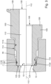
- Figure 2 shows a perspective view of the connection adapter 100 for arrangement at the fluid channel opening 10.
- the fluid channel 110 runs along a longitudinal axis 112 of the connection adapter 100.
- the second connection geometry 104 faces the valve body 4 and comprises a fixing section 114 and a sealing section 116.
- the first connection geometry 14 is designed as a recess 36 in the valve body 4, so that the second connection geometry 104 protrudes into the recess 36 in the installed state.
- the first connection geometry 14 comprises a fixing section 1114 and a sealing section 1116.
- the fixing sections 114 and 1114 are designed as threads which engage with one another. By designing the fixing sections 114 and 1114 as interlocking threads, the connection adapter 100 is detachably arranged on the valve body 4.
- the connection between the connection adapter 100 and the valve body 4 is achieved alternatively or additionally by at least one of the following types of connection: bayonet lock, a clamping ring, a clip-in connection, the connection with a union nut, welding and gluing.
- the sealing section 116 comprises a lateral annular groove in which an O-ring 126 is arranged as an elastic sealing element. This O-ring interacts with an inner surface of the cylinder jacket of the sealing section 1116 in such a way that the tightness of the valve body system 2 to the outside is ensured.
- the first connection geometry 14 is essentially rotationally symmetrical about a longitudinal axis 1000.
- the longitudinal axes 1000 and 112 coincide in the installed state of the connection adapter 100.
- the third connection geometry 108 is a clamp connection geometry, which is realized on a nozzle basis.
- a welded connection in the form of a pipe or nozzle can be part of the third connection geometry 108.
- the connection adapter 100 comprises a lateral engagement contour 120, which a tool can engage in order to carry out assembly or disassembly of the connection adapter 100 by rotating the connection adapter 100 about the longitudinal axis 112.
- connection geometry 14 is arranged on a projection protruding from the valve body 4 and the connection adapter 100 has a recess with the second connection geometry 104.
- Figure 3 shows a perspective view of two examples of the connection adapter 100.
- the two examples are separated from each other along the longitudinal axis 112.
- the upper half shows the connection adapter 100 from Figure 2 .
- the O-ring 126 is arranged in a lateral circumferential annular groove of the sealing section 116.
- the recess 36 tapers from the fixing section 1114 towards the sealing section 1116.
- the sealing section 116 and the fixing section 114 are thus spaced apart from one another.
- a distal annular surface 122 of the second connection geometry of the connection adapter 100 lies on an annular surface 1122 of the first connection geometry of the valve body 4.
- connection adapter 100 in a further embodiment not claimed.
- the third Connection geometry 108 is compared to the connection geometry 108 of the embodiment from Figure 2 shortened.
- the diameter of the fluid channel 110 is reduced compared to the diameter of the fluid channel 12.
- a chamfer 124 which provides a diameter taper in the area of the fluid channel 110. The chamfer 124 serves to optimize the flow.
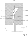
- Figure 4 shows an example of the sealing sections 116 and 1116.
- the sealing section 1116 of the first connection geometry of the valve body 4 is provided by the surface 1122, which follows an imaginary vertical plane of the longitudinal axis of the recess 36.
- the sealing section 116 of the connection adapter 100 provides a circular ring-shaped raised sealing contour 130, which is pressed onto the surface 1122, which can also be referred to as a contact surface, by screwing the connection adapter 100 into the recess 36.
- the sealing contour 130 protrudes from a surface 132 surrounding it and thus forms a distal end of the connection adapter 100. This provides an elastomer-free seal.
- This example of the sealing sections 116 and 1116 is of course compatible with the design according to the Figure 3 combinable.
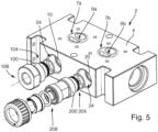
- Figure 5 shows an example of the modular valve body system 2, wherein the valve body 4 is a valve block.
- the valve seats 6a and 6b are accessible via respective openings 7a and 7b of the valve body 4.
- the respective fluid channel opening 10, 20 is connected to the respective valve seat 6a, 6b in a fluid-conducting manner.
- the two connection adapters 100 and 200 are designed identically with regard to their second connection geometry 104, 204.
- the third connection geometries 108 and 208 differ from each other, however.
- the first connection geometries 14, 24 and the second connection geometries 104, 204 are, however, designed such that the two connection adapters 100 and 200 with their respective second connection geometry can be arranged in the other first connection geometry 24, 14 in a pull-out-proof manner.
Landscapes
- Engineering & Computer Science (AREA)
- General Engineering & Computer Science (AREA)
- Mechanical Engineering (AREA)
- Lift Valve (AREA)
- Valve Housings (AREA)
Description
- Die Erfindung betrifft ein modulares Ventilkörpersystem.
-
DE 20 2013 002 441 U1 offenbart bereits ein modulares Ventilkörpersystem gemäß dem Oberbegriff von Anspruch 1. -
WO 2017/063707 A1 offenbart eine Ventileinrichtung zur Beeinflussung eines Fluidstroms, mit einem Grundkörper, der eine Ventilausnehmung zur Aufnahme eines beweglich gelagerten Ventilkörpers aufweist und der von wenigstens zwei Fluidkanälen durchsetzt ist, die sich zwischen der Ventilausnehmung und Anschlussausnehmungen in Außenflächen des Grundkörpers erstrecken, wobei die beiden Fluidkanäle einen Winkel von weniger als 180 Grad, insbesondere von 90 Grad, einnehmen und jeweils an einem der Ventilausnehmung zugewandten Endbereich einen Ventilsitz (34) aufweisen, der für eine abdichtende Anlage eines Ventilkörpers ausgebildet ist, und mit einer Antriebseinrichtung, die einen Aktor und einen dem Aktor zugeordneten, beweglich gelagerten Ventilkörper umfasst. - Ventilblöcke umfassen bekanntlich materialschlüssig mit dem Material des Ventilblocks verbundene Anschlüsse. Rohrleitungen werden direkt mit den vorgenannten Anschlüssen verbunden.
- Mithin ist es Aufgabe der Erfindung, die bekannten Ventilblöcke bzw. Ventilkörper zu verbessern.
- Die der Erfindung zugrunde liegende Aufgabe wird durch ein modulares Ventilkörpersystem gemäß dem Anspruch 1 gelöst. Vorteilhafte Weiterbildungen sind in den Unteransprüchen angegeben.
- Mittels der ersten und zweiten Anschlussgeometrien wird also eine vereinheitlichte Schnittstelle zwischen dem Ventilkörper und den Anschlussadaptern bereitgestellt, womit der Ventilkörper und die Anschlussadapter unabhängig voneinander fertigbar sind. Vorteilhaft ergeben sich somit Freiheitsgrade bei der Gestaltung der dritten Anschlussgeometrie, des Anschlussfluidkanals und der vom Ventilkörper abgewandten Adapteröffnung. Die dritte Anschlussgeometrie kann beispielsweise einen Stutzen, einen Schweißabschnitt oder eine andere Geometrie umfassen - je nach gewünschter Anschlussart zwischen dem jeweiligen Anschlussadapter und einem Rohrstück.
- Das modulare Ventilkörpersystem bietet insbesondere bei Ventilblöcken, welche mehrere Ventilsitze und mehr als zwei Fluidkanalöffnungen bereitstellen, umfassende Vorteile. So verringert die Fertigung von Standardblöcken mit höherer Stückzahl den Konstruktionsaufwand sowie die Rüst- und Fertigungskosten. Die Angebots- und Lieferzeiten werden deutlich gesenkt, da das Baukastenprinzip eine Lagerfertigung ermöglicht. Eine frühzeitige Bestellung durch den Kunden ist somit bereits während der Planungsphase einer Anlage möglich, da die endgültige Zusammenstellung zu einem späteren Zeitpunkt erfolgen kann. Wird ein Adapteranschluss nicht mehr benötigt oder wird er beschädigt, kann dieser mit geringem Montageaufwand getauscht werden. Die Ausführung der Adapteranschlüsse als separate Bauteile verringert das Zerspanungsvolumen sowie die Zerspanungszeit und führt somit zu fertigungstechnischen sowie umwelttechnischen Vorzügen.
- Ein vorteilhaftes Beispiel zeichnet sich dadurch aus, dass die wenigstens zwei Anschlussadapter lösbar zu dem Ventilkörper festgelegt sind. Vorteilhaft können defekte Anschlussadapter ausgetauscht werden. Auch können fehlerhaft angeordnete Anschlussadapter mit einer nicht passenden dritten Anschlussgeometrie gegen einen anderen Anschlussadapter mit passender dritter Anschlussgeometrie ausgetauscht werden.
- Erfindungsgemäß umfassen Festlegungsabschnitte der ersten Anschlussgeometrie und der zweiten Anschlussgeometrie ineinandergreifende Gewinde. Das Vorsehen ineinandergreifender Gewinde ermöglicht die ausziehsichere Festlegung der Anschlussadapter.
- Erfindungsgemäß umfasst der jeweilige Anschlussadapter eine laterale Angriffskontur für ein Werkzeug. Mittels des Werkzeugs, welches an der Angriffskontur angreift, lässt sich der jeweilige Anschlussadapter mit dem gewünschten Drehmoment zu dem Ventilkörper festlegen.
- Ein vorteilhaftes Beispiel zeichnet sich dadurch aus, dass eine jeweilige Ausnehmung in dem Ventilkörper die jeweilige erste Anschlussgeometrie bereitstellt, und wobei die jeweilige Ausnehmung zu der jeweiligen Fluidkanalöffnung des Ventilkörpers führt. Die Bereitstellung der ersten Anschlussgeometrie mittels einer Ausnehmung bietet den Vorteil, dass vom Ventilkörper abstehende Abschnitte vermieden werden. Darüber hinaus ist die Ausnehmung aus fertigungstechnischer Sicht einfach in den Ventilkörper einzubringen.
- Ein vorteilhaftes Beispiel zeichnet sich dadurch aus, dass ein jeweiliger der Anschlussadapter mit seiner zweiten Anschlussgeometrie in die jeweilige Ausnehmung eingebracht ist. Dadurch wird die Festlegung des Anschlussadapters bauraumeffizient innerhalb des Ventilkörpers realisiert.
- Ein Dichtabschnitt der ersten oder zweiten Anschlussgeometrie hält ein elastisches Dichtelement, welches die erste oder zweite Anschlussgeometrie kreisringförmig umgibt. Durch das elastische Dichtelement in Form eines Elastomer-O-Rings wird die Dichtheit des modularen Ventilsystems nach außen sichergestellt.
- Ein vorteilhaftes Beispiel zeichnet sich dadurch aus, dass eine Dichtung zwischen der ersten und zweiten Anschlussgeometrie elastomerfrei ausgeführt ist. Durch die elastomerfreie Dichtung können auch hochsensible Prozessmedien verarbeitet werden.
- Ein vorteilhaftes Beispiel zeichnet sich dadurch aus, dass ein bzw. der Dichtabschnitt der ersten oder zweiten Anschlussgeometrie eine parallel zu einer Längsachse des Anschlussadapters erhabene Dichtkontur umfasst, und wobei ein bzw. der Dichtabschnitt der zweiten oder ersten Anschlussgeometrie eine einer gedachten Lotebene der Längsachse folgende Anlagefläche für die Dichtkontur umfasst. Über die erhabene Dichtkontur wird die elastomerfreie Dichtung realisiert. In Verbindung mit den ineinandergreifenden Gewinden wird der jeweilige Anschlussadapter auf Block angezogen und damit die Dichtung bereitgestellt.
- Ein vorteilhaftes Beispiel zeichnet sich dadurch aus, dass ein jeweiliger bzw. der jeweilige Dichtabschnitt zwischen der Fluidkanalöffnung und dem Befestigungsabschnitt angeordnet ist. Vorteilhaft wird damit sichergestellt, dass der Befestigungsabschnitt nicht mit Prozessfluid in Kontakt kommt. Die sichere Festlegung der Anschlussadapter an dem Ventilkörper wird somit gewährleistet.
- Ein vorteilhaftes Beispiel zeichnet sich dadurch aus, dass das Ventilkörpersystem wenigstens einen Verschlussadapter mit einer dem Ventilkörper zugewandten vierten Anschlussgeometrie umfasst, wobei der Verschlussadapter die zugeordnete Fluidkanalöffnung verschließt, und wobei der Verschlussadapter mittels der ersten und der vierten Anschlussgeometrie ausziehsicher zu dem Ventilkörper festgelegt ist.
- Ein erfindungsgemäßes Ausführungsbeispiel zeichnet sich dadurch aus, dass der Ventilkörper ein Ventilblock ist, und wenigstens zwei Ventilsitze und wenigstens drei Fluidkanalöffnungen umfasst. Weitere Vorteile und Merkmale finden sich in der nachfolgenden Beschreibung von Ausführungsbeispielen, wobei auch für unterschiedliche Ausführungsformen die gleichen Bezugszeichen verwendet werden, ohne dass hierauf nochmals explizit hingewiesen wird. In der Zeichnung zeigen:
- Figur 1
- ein modulares Ventilkörpersystem in einer schematischen Ansicht;
- Figur 2
- einen Anschlussadapter zur Anordnung an einem Ventilkörper in perspektivischer Ansicht;
- Figur 3
- einen schematischen Schnitt von Beispielen des Ventilkörpersystems;
- Figur 4
- ein Beispiel für Dichtabschnitte; und
- Figur 5
- in einem Beispiel das modulare Ventilkörpersystem.
-
Figur 1 zeigt ein modulares Ventilkörpersystem 2. Das Ventilkörpersystem 2 umfasst einen Ventilkörper 4, insbesondere einen Ventilblock, und eine Mehrzahl von Anschlussadaptern 100, 200. Der Ventilkörper 4 umfasst wenigstens einen Ventilsitz 6 und wenigstens zwei Fluidkanalöffnungen 10, 20 jeweiliger Fluidkanäle 12, 22. Die Fluidkanäle 12, 22 sind unmittelbar oder mittelbar mit dem Ventilsitz 6 verbunden. An die Fluidkanalöffnung 10, 20 schließt sich eine erste Anschlussgeometrie 14, 24 an. Die erste Anschlussgeometrie 14, 24 umgibt also die Fluidkanalöffnung 10, 20. - Der jeweilige Anschlussadapter 100, 200 umfasst eine dem Ventilkörper 4 zugewandte Fluidkanalöffnung 102, 202, an welche sich eine zweite Anschlussgeometrie 104, 204 anschließt. Der Anschlussadapter 100, 200 umfasst eine von dem Ventilkörper 4 abgewandte Fluidkanalöffnung 106, 206, an welche sich eine dritte Anschlussgeometrie 108,208 zum Anschluss eines Rohres anschließt. Ein Fluidkanal 110, 210 verbindet die Fluidkanalöffnung 102, 202 fluidführend mit der Fluidkanalöffnung 106, 206. Die erste Anschlussgeometrie 14, 24 komplementiert die zweite Anschlussgeometrie 104, 204 dahingehend, als dass der Anschlussadapter 100, 200 ausziehsicher zu dem Ventilkörper 4 festgelegt ist und die Öffnungen 10 und 102 bzw. 20 und 202 so aneinander anliegen, dass die Fluidkanäle 12 und 110 bzw. 22 und 210 einen gemeinsamen Fluidkanal bis zur jeweiligen Fluidkanalöffnung 106, 206 bilden. Die erste Anschlussgeometrie 14, 24 komplementiert die zweite Anschlussgeometrie 104, 204 dahingehend, als dass der geschaffene gemeinsame Fluidkanal nach außen hin fluiddicht abgedichtet ist.
- Ein Absperrelement 30 wie beispielsweise eine Membran wird von einem Antrieb 32 angetrieben und wirkt mit dem Ventilsitz 6 so zusammen, dass ein durch den Ventilkörper 4 fließender Strom eines Prozessfluids begrenzt wird. Selbstverständlich ist die gezeigte Darstellung nur beispielhaft, was die Anzahl der Sitze und die Anzahl der Fluidkanalöffnungen in dem Ventilkörper 4 angeht.
- Die erste Anschlussgeometrie 14, 24 des Ventilkörpers 4 ist gleich ausgebildet und gleich dimensioniert, um einen der Anschlussadapter 100, 200 mittels der zweiten Anschlussgeometrie 104, 204 aufzunehmen. Mithin ist ebenfalls die zweite Anschlussgeometrie 104, 204 gleich ausgebildet und gleich dimensioniert. Die der ersten Anschlussgeometrie 14, 24 handelt es sich also um eine erste geometrische Kontur an mehreren voneinander beabstandeten Abschnitten des Ventilblocks 4, welche mit der zweiten Anschlussgeometrie 104 und 204 im Sinne einer zweiten geometrischen Kontur des jeweiligen Anschlussadapters 100, 200 so zusammenwirkt, dass die gewünschte dritte Anschlussgeometrie 108, 208 bereitgestellt wird. Damit korrespondieren die ersten Anschlussgeometrien 14, 24 zueinander. Die zweiten Anschlussgeometrien 104, 204 korrespondieren zueinander. Selbstverständlich können weitere aufeinander abgestimmte erste und zweite Anschlussgeometrien vorhanden sein, um beispielsweise unterschiedlich dimensionierte Fluidkanaldurchmesser und/oder -öffnungen an demselben Ventilkörper 4 zu realisieren.
- Das Ventilkörpersystem 2 kann in einer Ausführungsform einen Verschlussadapter aufweisen, welcher mittels einer vierten Anschlussgeometrie in die erste Anschlussgeometrie 14, 24 eingreift und die Fluidkanalöffnung 10, 20 fluiddicht verschließt.
-
Figur 2 zeigt eine perspektivische Darstellung des Anschlussadapters 100 zur Anordnung an der Fluidkanalöffnung 10. Der Fluidkanal 110 verläuft entlang einer Längsachse 112 des Anschlussadapters 100. Die zweite Anschlussgeometrie 104 ist dem Ventilkörper 4 zugewandt und umfasst einen Festlegungsabschnitt 114 sowie einen Dichtabschnitt 116. - Die erste Anschlussgeometrie 14 ist als Ausnehmung 36 in dem Ventilkörper 4 ausgebildet, sodass die zweite Anschlussgeometrie 104 in die Ausnehmung 36 im verbauten Zustand hineinragt. Die erste Anschlussgeometrie 14 umfasst einen Festlegungsabschnitt 1114 und einen Dichtabschnitt 1116. Die Festlegungsabschnitte 114 und 1114 sind vorliegend als Gewinde ausgebildet, welche ineinandergreifen. Durch die Ausführung der Festlegungsabschnitte 114 und 1114 als ineinandergreifende Gewinde ist der Anschlussadapter 100 lösbar an dem Ventilkörper 4 angeordnet. Die Verbindung zwischen dem Anschlussadapter 100 und dem Ventilkörper 4 wird alternativ oder zusätzlich durch wenigstens eine der folgenden Verbindungsarten erreicht: Bajonett-Verschluss, ein Spannring, eine Einclips-Verbindung, die Verbindung mit einer Überwurfmutter, Schweißen und Kleben.
- Der Dichtabschnitt 116 umfasst eine laterale Ringnut, in welcher ein O-Ring 126 als elastisches Dichtelement angeordnet ist. Dieser O-Ring wirkt mit einer Zylindermantelinnenfläche des Dichtabschnitts 1116 derart zusammen, dass die Dichtheit des Ventilkörpersystems 2 nach außen gewährleistet ist.
- Die erste Anschlussgeometrie 14 ist im Wesentlichen rotationssymmetrisch um eine Längsachse 1000 ausgebildet. Die Längsachsen 1000 und 112 fallen im verbauten Zustand des Anschlussadapters 100 zusammen. Die dritte Anschlussgeometrie 108 ist vorliegend eine Clamp-Anschlussgeometrie, welche auf Stutzenbasis realisiert wird. Selbstverständlich kann alternativ ein Schweißanschluss in Rohrform bzw. Stutzenform Teil der dritte Anschlussgeometrie 108 sein. Des Weiteren umfasst den Anschlussadapter 100 eine laterale Angriffskontur 120, an welche ein Werkzeug angreifen kann, um durch eine Drehung des Anschlussadapters 100 um die Längsachse 112 eine Montage oder Demontage des Anschlussadapters 100 durchzuführen.
- Alternativ zu dem dargestellten Beispiel ist in einem weiteren Beispiel die erste Anschlussgeometrie 14 an einem von dem Ventilkörper 4 abragenden Vorsprung angeordnet und der Anschlussadapter 100 weist eine Ausnehmung mit der zweiten Anschlussgeometrie 104 auf.
-
Figur 3 zeigt eine perspektivische Darstellung zweier Beispiele des Anschlussadapters 100. Die beiden Beispiele sind entlang der Längsachse 112 voneinander getrennt. Aus Gründen der Übersichtlichkeit werden die gleichen Bezugszeichen für beide Beispiele verwendet. Die obere Hälfte zeigt den Anschlussadapter 100 ausFigur 2 . Der O-Ring 126 ist in einer lateralen umfänglichen Ringnut des Dichtabschnitts 116 angeordnet. Die Ausnehmung 36 verjüngt sich ausgehend von dem Festlegungsabschnitte 1114 hin zu dem Dichtabschnitt 1116. Der Dichtabschnitt 116 und der Festlegungsabschnitt 114 sind damit voneinander beabstandet. Eine distale kreisringförmige Fläche 122 der zweiten Anschlussgeometrie des Anschlussadapters 100 liegt an einer kreisringförmigen Fläche 1122 der ersten Anschlussgeometrie des Ventilkörpers 4. - Die untere Hälfte der
Figur 3 zeigt den Anschlussadapter 100 in einer weiteren nicht beanspruchten Ausführungsform. Die dritte Anschlussgeometrie 108 ist gegenüber der Anschlussgeometrie 108 des Ausführungsbeispiels ausFigur 2 verkürzt. Des Weiteren ist der Durchmesser des Fluidkanals 110 gegenüber dem Durchmesser des Fluidkanals 12 verringert. Unmittelbar an die Öffnung 102 schließt sich eine Fase 124 an, welche eine Durchmesserverjüngung im Bereich des Fluidkanals 110 bereitstellt. Die Fase 124 dient zur Strömungsoptimierung. -
Figur 4 zeigt ein Beispiel der Dichtabschnitte 116 und 1116. Der Dichtabschnitt 1116 der ersten Anschlussgeometrie des Ventilkörpers 4 wird durch die Fläche 1122 bereitgestellt, welche einer gedachten Lotebene der Längsachse der Ausnehmung 36 folgt. Der Dichtabschnitt 116 des Anschlussadapters 100 stellt eine kreisringförmige erhabene Dichtkontur 130 bereit, welche über das Eindrehen des Anschlussadapters 100 in die Ausnehmung 36 auf die Fläche 1122, welche auch als Anlagefläche bezeichenbar ist, gedrückt wird. Die Dichtkontur 130 steht gegenüber einer diese umgebenden Fläche 132 hervor und bildet damit ein distales Ende des Anschlussadapters 100. Damit wird eine elastomerfreie Dichtung bereitgestellt. Dieses Beispiel der Dichtabschnitte 116 und 1116 ist selbstverständlich mit der Ausführung gemäß derFigur 3 kombinierbar. -
Figur 5 zeigt in einem Beispiel das modulare Ventilkörpersystem 2, wobei der Ventilkörper 4 ein Ventilblock ist. Die Ventilsitze 6a und 6b sind über jeweilige Öffnungen 7a und 7b des Ventilkörpers 4 zugänglich. Die jeweilige Fluidkanalöffnung 10, 20 ist fluidführend mit dem jeweiligen Ventilsitz 6a, 6b verbunden. Die beiden Anschlussadapter 100 und 200 sind hinsichtlich ihrer zweiten Anschlussgeometrie 104, 204 gleich ausgebildet. Die dritten Anschlussgeometrien 108 und 208 unterscheiden sich jedoch voneinander. Die ersten Anschlussgeometrien 14, 24 und die zweiten Anschlussgeometrien 104, 204 sind hingegen derart ausgestaltet, dass die beiden Anschlussadapter 100 und 200 mit ihrer jeweiligen zweiten Anschlussgeometrie in der jeweils anderen ersten Anschlussgeometrie 24, 14 ausziehsicher anordenbar sind.
Claims (9)
- Ein modulares Ventilblocksystem (2),bei dem eine Membran von einem Antrieb (32) angetrieben wird und mit einem jeweiligen von zwei Ventilsitzen (6) so zusammenwirkt, dass ein durch einen Ventilblock (4) fließender Strom eines Prozessfluids begrenzt wird,das modulare Ventilblocksystem (2) umfassend:- den Ventilblock (4), der wenigstens die zwei Ventilsitze (6) und wenigstens drei Fluidkanalöffnungen (10, 20) jeweiliger Fluidkanäle (12, 22), welche fluidführend mit einem jeweiligen der Ventilsitze (6) verbunden sind, umfasst, wobei eine erste Anschlussgeometrie (14; 24) sich an die jeweilige Fluidkanalöffnung (10; 20) anschließt, und- wenigstens drei Anschlussadapter (100, 200), wobei ein jeweiliger der Anschlussadapter (100; 200) zwei über einen Anschlussfluidkanal (110; 210) miteinander verbundene Fluidkanalöffnungen (102, 106; 202, 206) umfasst,wobei eine zweite Anschlussgeometrie (104; 204) sich an die dem Ventilblock (4) zugewandte Fluidkanalöffnung (102; 202) des jeweiligen Anschlussadapters (100; 200) anschließt, wobei eine dritte Anschlussgeometrie (108; 208) sich an die von dem Ventilblock (4) abgewandte Fluidkanalöffnung (106; 206) des jeweiligen Anschlussadapters (100; 200) anschließt, wobei Festlegungsabschnitte (114, 1114) der ersten Anschlussgeometrie (14; 24) und der zweiten Anschlussgeometrie (104; 204) ineinandergreifende Gewinde umfassen, die den jeweiligen Anschlussadapter (100; 200) ausziehsicher zu dem Ventilblock (4) festlegen,wobei ein Dichtabschnitt (1116; 116) der ersten oder zweiten Anschlussgeometrie (14; 104; 24; 204) ein elastisches Dichtelement (126) hält, das ein O-Ring ist, undwobei die jeweilige Fluidkanalöffnung (10, 20) des Ventilblocks (4) und die dem Ventilblock (4) zugewandte Fluidkanalöffnung (102, 202) des jeweiligen Anschlussadapters (100, 200) so aneinander anliegen, dass die der jeweilige Fluidkanal (12, 22) des Ventilblocks (4) und der Anschlussfluidkanal (110; 210) des Anschlussadapters (100, 200) einen gemeinsamen Fluidkanal bis zur von dem Ventilblock (4) abgewandten Fluidkanalöffnung (106, 206) des Anschlussadapters (100, 200) bilden,dadurch gekennzeichnet, dassdas elastische Dichtelement die erste oder zweite Anschlussgeometrie (14; 104; 24; 204) kreisringförmig umgibt,dass der Dichtabschnitt (1116; 116) eine laterale Ringnut umfasst, in der der O-Ring angeordnet ist, der mit einer Zylindermantelinnenfläche des Dichtabschnitts (1116; 116) derart zusammenwirkt, dass die Dichtheit des Ventilblocksystems (2) nach außen gewährleistet ist, dass der jeweilige Anschlussadapter (100; 200) eine laterale Angriffskontur (120) für ein Werkzeug umfasst, mittels der sich der jeweilige Anschlussadapter (100; 200) mit dem gewünschten Drehmoment zu dem Ventilblock (4) festlegen lässt,dass an der lateralen Angriffskontur (120) das Werkzeug angreifen kann, um durch eine Drehung des Anschlussadapters (100), der zweiten Anschlussgeometrie (104), des Festlegungsabschnitts (114) sowie des Dichtabschnitts (116) um eine Längsachse (112) eine Montage oder Demontage des Anschlussadapters (100) durchzuführen, unddass der Fluidkanal (12, 22) des Ventilblocks (4) und der zugeordnete Anschlussfluidkanal (110; 210) des Anschlussadapters (100, 200) bündig ineinander übergehen.
- Das modulare Ventilblocksystem (2) gemäß dem Anspruch 1, wobei die wenigstens drei Anschlussadapter (100, 200) lösbar zu dem Ventilblock (4) festgelegt sind.
- Das modulare Ventilblocksystem (2) gemäß einem der vorigen Ansprüche, wobei eine jeweilige Ausnehmung (36) in dem Ventilblock (4) die jeweilige erste Anschlussgeometrie (14; 24) bereitstellt, und wobei die jeweilige Ausnehmung (36) zu der jeweiligen Fluidkanalöffnung (10; 20) des Ventilblocks (4) führt.
- Das modulare Ventilblocksystem (2) gemäß dem Anspruch 3, wobei ein jeweiliger der Anschlussadapter (100; 200) mit seiner zweiten Anschlussgeometrie (104; 204) in die jeweilige Ausnehmung (36) eingebracht ist.
- Das modulare Ventilblocksystem (2) gemäß einem der vorigen Ansprüche, wobei eine Dichtung zwischen der ersten und zweiten Anschlussgeometrie (14, 104; 24, 204) elastomerfrei ausgeführt ist.
- Das modulare Ventilblocksystem (2) gemäß einem der vorigen Ansprüche, wobei ein bzw. der Dichtabschnitt (1116; 116) der ersten oder zweiten Anschlussgeometrie (14; 104; 24; 204) eine parallel zu einer Längsachse (112) des Anschlussadapters (100) erhabene Dichtkontur (130) umfasst, und wobei ein bzw. der Dichtabschnitt (1116; 116) der zweiten oder ersten Anschlussgeometrie (24; 204; 14; 104) eine einer gedachten Lotebene der Längsachse (112) folgende Anlagefläche (1122) für die Dichtkontur (130) umfasst.
- Das modulare Ventilblocksystem (2) gemäß einem der vorigen Ansprüche, wobei ein jeweiliger bzw. der jeweilige Dichtabschnitt (1116; 116) zwischen der Fluidkanalöffnung (10; 102) und dem Befestigungsabschnitt (1114; 114) angeordnet ist.
- Das modulare Ventilblocksystem (2) gemäß einem der vorstehenden Ansprüche, wobei das Ventilblocksystem (2) wenigstens einen Verschlussadapter mit einer dem Ventilblock (4) zugewandten vierten Anschlussgeometrie umfasst, wobei der Verschlussadapter die zugeordnete Fluidkanalöffnung (10; 20) des Ventilblocks (4) verschließt, und wobei der Verschlussadapter mittels der ersten und der vierten Anschlussgeometrie ausziehsicher zu dem Ventilblock (4) festgelegt ist.
- Das modulare Ventilblocksystem (2) gemäß dem Anspruch 1, wobei der Durchmesser des Fluidkanals (12, 22) des Ventilblocks (4) größer ist als der der Durchmesser des zugeordneten Anschlussfluidkanals (110; 210) des Anschlussadapters (100, 200).
Applications Claiming Priority (2)
| Application Number | Priority Date | Filing Date | Title |
|---|---|---|---|
| DE102019104490.1A DE102019104490A1 (de) | 2019-02-21 | 2019-02-21 | Modulares Ventilkörpersystem |
| PCT/EP2020/054533 WO2020169763A1 (de) | 2019-02-21 | 2020-02-20 | Modulares ventilkörpersystem |
Publications (3)
| Publication Number | Publication Date |
|---|---|
| EP3928012A1 EP3928012A1 (de) | 2021-12-29 |
| EP3928012C0 EP3928012C0 (de) | 2025-01-22 |
| EP3928012B1 true EP3928012B1 (de) | 2025-01-22 |
Family
ID=69740326
Family Applications (1)
| Application Number | Title | Priority Date | Filing Date |
|---|---|---|---|
| EP20708444.3A Active EP3928012B1 (de) | 2019-02-21 | 2020-02-20 | Modulares ventilkörpersystem |
Country Status (3)
| Country | Link |
|---|---|
| EP (1) | EP3928012B1 (de) |
| DE (1) | DE102019104490A1 (de) |
| WO (1) | WO2020169763A1 (de) |
Families Citing this family (2)
| Publication number | Priority date | Publication date | Assignee | Title |
|---|---|---|---|---|
| TWI842659B (zh) | 2021-07-28 | 2024-05-11 | 美商艾克爾系統公司 | 模組化配件組件以及包含該組件的系統 |
| DE102023100893B4 (de) | 2023-01-16 | 2026-03-12 | Deutsches Zentrum für Luft- und Raumfahrt e.V. | Ventilvorrichtung zur Umschaltung eines Strömungsweges eines Fluids, Temperieranordnung und Verfahren zur Herstellung |
Citations (1)
| Publication number | Priority date | Publication date | Assignee | Title |
|---|---|---|---|---|
| DE19725999C1 (de) * | 1997-06-19 | 1998-11-05 | Festo Ag & Co | Steckverbindungseinrichtung sowie mit einer oder mehreren Steckverbindungseinrichtungen ausgestattete Fluidverteilereinrichtung |
Family Cites Families (5)
| Publication number | Priority date | Publication date | Assignee | Title |
|---|---|---|---|---|
| GB854133A (en) * | 1958-01-01 | 1960-11-16 | Ml Aviation Co Ltd | Improvements relating to high pressure pipe unions |
| DE3816749A1 (de) * | 1988-05-17 | 1989-11-30 | Teves Gmbh Alfred | Vorrichtung fuer einen hydraulischen anschluss |
| ITBS20120097A1 (it) * | 2012-06-28 | 2013-12-29 | Emer Spa | Valvola con corpo in alluminio e sistema anticorrosione |
| DE202013002441U1 (de) * | 2013-03-07 | 2014-06-10 | Gemü Gebr. Müller Apparatebau Gmbh & Co. Kommanditgesellschaft | Mehrwegeventilblock |
| WO2017063707A1 (de) * | 2015-10-15 | 2017-04-20 | Festo Ag & Co. Kg | Ventileinrichtung |
-
2019
- 2019-02-21 DE DE102019104490.1A patent/DE102019104490A1/de not_active Withdrawn
-
2020
- 2020-02-20 EP EP20708444.3A patent/EP3928012B1/de active Active
- 2020-02-20 WO PCT/EP2020/054533 patent/WO2020169763A1/de not_active Ceased
Patent Citations (1)
| Publication number | Priority date | Publication date | Assignee | Title |
|---|---|---|---|---|
| DE19725999C1 (de) * | 1997-06-19 | 1998-11-05 | Festo Ag & Co | Steckverbindungseinrichtung sowie mit einer oder mehreren Steckverbindungseinrichtungen ausgestattete Fluidverteilereinrichtung |
Also Published As
| Publication number | Publication date |
|---|---|
| EP3928012C0 (de) | 2025-01-22 |
| EP3928012A1 (de) | 2021-12-29 |
| DE102019104490A1 (de) | 2020-08-27 |
| WO2020169763A1 (de) | 2020-08-27 |
Similar Documents
| Publication | Publication Date | Title |
|---|---|---|
| DE69011698T2 (de) | Flüssigkeitskupplungseinrichtung. | |
| DE2313983C2 (de) | Einrichtung zur Steuerung und/oder Konditionierung eines Fluids mit mindestens einer Steuer- oder Konditioniervorrichtung | |
| DE10085364B4 (de) | Bauteil-zu-Bauteil Dichtverfahren | |
| EP1196703B1 (de) | Abdichtung für medienführende teile | |
| DE102013200533B4 (de) | Ventilpatrone | |
| EP3928012B1 (de) | Modulares ventilkörpersystem | |
| DE102012012247B4 (de) | Ventilgehäuse und Baugruppe mit Ventilgehäuse und Verfahren zum Herstellen eines Ventilgehäuses | |
| EP0696699A1 (de) | Entleerventil | |
| EP2281132B1 (de) | Vorrichtung zur verrohrung von prozessanlagen der nahrungsmittel- und getränkeindustrie | |
| EP0507423B1 (de) | Leitungsrohrverbindung | |
| EP1561982B1 (de) | Armatur | |
| DE102008062873B4 (de) | Ventilgehäusekörper | |
| EP3683367B1 (de) | Waschbeckenmontageanordnung sowie verfahren zum zusammenbau einer waschbeckenmontageanordnung | |
| AT526935B1 (de) | Steckverbinder | |
| DE102012004937B4 (de) | Hilfsvorrichtung für ein Scheibenventil in einer Zwischenflanschausführung | |
| DE10064976A1 (de) | Armatur mit Anschlussadapter | |
| DE102013018174A1 (de) | Rohrverbindung und Vorrichtung für einen Tankinnenraum | |
| EP2146773B1 (de) | Verfahren zur Herstellung einer Rohr- und Schlauchverbindung | |
| AT500163A2 (de) | Fluid-verteiler | |
| DE102011001237A1 (de) | Tiefenanschlag zum Einsatz in einem Werkzeughalter und eine Anordnung zur Übergabe von Kühl- und/oder Schmiermittel von einem Werkzeughalter an ein Werkzeug | |
| DE4402163A1 (de) | Armaturengehäuse | |
| EP3324085B1 (de) | Ring-block membranventil | |
| EP4682420A1 (de) | Leitungssystem mit zahlreichen abgängen | |
| EP4620552A1 (de) | Filterelement, ionentauscher-filterelement und filtersystem | |
| EP4614050A1 (de) | Verteiler und h2-hochdrucksystem |
Legal Events
| Date | Code | Title | Description |
|---|---|---|---|
| STAA | Information on the status of an ep patent application or granted ep patent |
Free format text: STATUS: UNKNOWN |
|
| STAA | Information on the status of an ep patent application or granted ep patent |
Free format text: STATUS: THE INTERNATIONAL PUBLICATION HAS BEEN MADE |
|
| PUAI | Public reference made under article 153(3) epc to a published international application that has entered the european phase |
Free format text: ORIGINAL CODE: 0009012 |
|
| STAA | Information on the status of an ep patent application or granted ep patent |
Free format text: STATUS: REQUEST FOR EXAMINATION WAS MADE |
|
| 17P | Request for examination filed |
Effective date: 20210901 |
|
| AK | Designated contracting states |
Kind code of ref document: A1 Designated state(s): AL AT BE BG CH CY CZ DE DK EE ES FI FR GB GR HR HU IE IS IT LI LT LU LV MC MK MT NL NO PL PT RO RS SE SI SK SM TR |
|
| DAV | Request for validation of the european patent (deleted) | ||
| DAX | Request for extension of the european patent (deleted) | ||
| STAA | Information on the status of an ep patent application or granted ep patent |
Free format text: STATUS: EXAMINATION IS IN PROGRESS |
|
| 17Q | First examination report despatched |
Effective date: 20220922 |
|
| GRAP | Despatch of communication of intention to grant a patent |
Free format text: ORIGINAL CODE: EPIDOSNIGR1 |
|
| STAA | Information on the status of an ep patent application or granted ep patent |
Free format text: STATUS: GRANT OF PATENT IS INTENDED |
|
| INTG | Intention to grant announced |
Effective date: 20240826 |
|
| GRAS | Grant fee paid |
Free format text: ORIGINAL CODE: EPIDOSNIGR3 |
|
| GRAA | (expected) grant |
Free format text: ORIGINAL CODE: 0009210 |
|
| STAA | Information on the status of an ep patent application or granted ep patent |
Free format text: STATUS: THE PATENT HAS BEEN GRANTED |
|
| AK | Designated contracting states |
Kind code of ref document: B1 Designated state(s): AL AT BE BG CH CY CZ DE DK EE ES FI FR GB GR HR HU IE IS IT LI LT LU LV MC MK MT NL NO PL PT RO RS SE SI SK SM TR |
|
| RAP3 | Party data changed (applicant data changed or rights of an application transferred) |
Owner name: GEMUE GEBR. MUELLER APPARATEBAU GMBH & CO.KOMMANDITGESELLSCHAFT |
|
| REG | Reference to a national code |
Ref country code: GB Ref legal event code: FG4D Free format text: NOT ENGLISH |
|
| REG | Reference to a national code |
Ref country code: CH Ref legal event code: EP |
|
| REG | Reference to a national code |
Ref country code: IE Ref legal event code: FG4D Free format text: LANGUAGE OF EP DOCUMENT: GERMAN |
|
| REG | Reference to a national code |
Ref country code: DE Ref legal event code: R096 Ref document number: 502020010254 Country of ref document: DE |
|
| U01 | Request for unitary effect filed |
Effective date: 20250203 |
|
| U07 | Unitary effect registered |
Designated state(s): AT BE BG DE DK EE FI FR IT LT LU LV MT NL PT RO SE SI Effective date: 20250207 |
|
| U20 | Renewal fee for the european patent with unitary effect paid |
Year of fee payment: 6 Effective date: 20250212 |
|
| PGFP | Annual fee paid to national office [announced via postgrant information from national office to epo] |
Ref country code: GB Payment date: 20250218 Year of fee payment: 6 |
|
| PG25 | Lapsed in a contracting state [announced via postgrant information from national office to epo] |
Ref country code: RS Free format text: LAPSE BECAUSE OF FAILURE TO SUBMIT A TRANSLATION OF THE DESCRIPTION OR TO PAY THE FEE WITHIN THE PRESCRIBED TIME-LIMIT Effective date: 20250422 |
|
| PG25 | Lapsed in a contracting state [announced via postgrant information from national office to epo] |
Ref country code: PL Free format text: LAPSE BECAUSE OF FAILURE TO SUBMIT A TRANSLATION OF THE DESCRIPTION OR TO PAY THE FEE WITHIN THE PRESCRIBED TIME-LIMIT Effective date: 20250122 |
|
| PG25 | Lapsed in a contracting state [announced via postgrant information from national office to epo] |
Ref country code: ES Free format text: LAPSE BECAUSE OF FAILURE TO SUBMIT A TRANSLATION OF THE DESCRIPTION OR TO PAY THE FEE WITHIN THE PRESCRIBED TIME-LIMIT Effective date: 20250122 |
|
| PG25 | Lapsed in a contracting state [announced via postgrant information from national office to epo] |
Ref country code: NO Free format text: LAPSE BECAUSE OF FAILURE TO SUBMIT A TRANSLATION OF THE DESCRIPTION OR TO PAY THE FEE WITHIN THE PRESCRIBED TIME-LIMIT Effective date: 20250422 Ref country code: IS Free format text: LAPSE BECAUSE OF FAILURE TO SUBMIT A TRANSLATION OF THE DESCRIPTION OR TO PAY THE FEE WITHIN THE PRESCRIBED TIME-LIMIT Effective date: 20250522 |
|
| PG25 | Lapsed in a contracting state [announced via postgrant information from national office to epo] |
Ref country code: HR Free format text: LAPSE BECAUSE OF FAILURE TO SUBMIT A TRANSLATION OF THE DESCRIPTION OR TO PAY THE FEE WITHIN THE PRESCRIBED TIME-LIMIT Effective date: 20250122 |
|
| PG25 | Lapsed in a contracting state [announced via postgrant information from national office to epo] |
Ref country code: GR Free format text: LAPSE BECAUSE OF FAILURE TO SUBMIT A TRANSLATION OF THE DESCRIPTION OR TO PAY THE FEE WITHIN THE PRESCRIBED TIME-LIMIT Effective date: 20250423 |
|
| PGFP | Annual fee paid to national office [announced via postgrant information from national office to epo] |
Ref country code: CH Payment date: 20250407 Year of fee payment: 6 |
|
| PG25 | Lapsed in a contracting state [announced via postgrant information from national office to epo] |
Ref country code: SM Free format text: LAPSE BECAUSE OF FAILURE TO SUBMIT A TRANSLATION OF THE DESCRIPTION OR TO PAY THE FEE WITHIN THE PRESCRIBED TIME-LIMIT Effective date: 20250122 |
|
| PG25 | Lapsed in a contracting state [announced via postgrant information from national office to epo] |
Ref country code: MC Free format text: LAPSE BECAUSE OF FAILURE TO SUBMIT A TRANSLATION OF THE DESCRIPTION OR TO PAY THE FEE WITHIN THE PRESCRIBED TIME-LIMIT Effective date: 20250122 |
|
| PG25 | Lapsed in a contracting state [announced via postgrant information from national office to epo] |
Ref country code: CZ Free format text: LAPSE BECAUSE OF FAILURE TO SUBMIT A TRANSLATION OF THE DESCRIPTION OR TO PAY THE FEE WITHIN THE PRESCRIBED TIME-LIMIT Effective date: 20250122 |
|
| PG25 | Lapsed in a contracting state [announced via postgrant information from national office to epo] |
Ref country code: SK Free format text: LAPSE BECAUSE OF FAILURE TO SUBMIT A TRANSLATION OF THE DESCRIPTION OR TO PAY THE FEE WITHIN THE PRESCRIBED TIME-LIMIT Effective date: 20250122 |
|
| PLBE | No opposition filed within time limit |
Free format text: ORIGINAL CODE: 0009261 |
|
| STAA | Information on the status of an ep patent application or granted ep patent |
Free format text: STATUS: NO OPPOSITION FILED WITHIN TIME LIMIT |
|
| 26N | No opposition filed |
Effective date: 20251023 |
|
| PG25 | Lapsed in a contracting state [announced via postgrant information from national office to epo] |
Ref country code: IE Free format text: LAPSE BECAUSE OF NON-PAYMENT OF DUE FEES Effective date: 20250220 |
|
| U20 | Renewal fee for the european patent with unitary effect paid |
Year of fee payment: 7 Effective date: 20260209 |