EP3926399A1 - Image forming method, image forming apparatus, and image forming program - Google Patents
Image forming method, image forming apparatus, and image forming program Download PDFInfo
- Publication number
- EP3926399A1 EP3926399A1 EP21178814.6A EP21178814A EP3926399A1 EP 3926399 A1 EP3926399 A1 EP 3926399A1 EP 21178814 A EP21178814 A EP 21178814A EP 3926399 A1 EP3926399 A1 EP 3926399A1
- Authority
- EP
- European Patent Office
- Prior art keywords
- image
- region
- colorant
- image region
- observation
- Prior art date
- Legal status (The legal status is an assumption and is not a legal conclusion. Google has not performed a legal analysis and makes no representation as to the accuracy of the status listed.)
- Pending
Links
Images




Classifications
-
- G—PHYSICS
- G03—PHOTOGRAPHY; CINEMATOGRAPHY; ANALOGOUS TECHNIQUES USING WAVES OTHER THAN OPTICAL WAVES; ELECTROGRAPHY; HOLOGRAPHY
- G03C—PHOTOSENSITIVE MATERIALS FOR PHOTOGRAPHIC PURPOSES; PHOTOGRAPHIC PROCESSES, e.g. CINE, X-RAY, COLOUR, STEREO-PHOTOGRAPHIC PROCESSES; AUXILIARY PROCESSES IN PHOTOGRAPHY
- G03C7/00—Multicolour photographic processes or agents therefor; Regeneration of such processing agents; Photosensitive materials for multicolour processes
- G03C7/30—Colour processes using colour-coupling substances; Materials therefor; Preparing or processing such materials
- G03C7/3022—Materials with specific emulsion characteristics, e.g. thickness of the layers, silver content, shape of AgX grains
-
- G—PHYSICS
- G03—PHOTOGRAPHY; CINEMATOGRAPHY; ANALOGOUS TECHNIQUES USING WAVES OTHER THAN OPTICAL WAVES; ELECTROGRAPHY; HOLOGRAPHY
- G03C—PHOTOSENSITIVE MATERIALS FOR PHOTOGRAPHIC PURPOSES; PHOTOGRAPHIC PROCESSES, e.g. CINE, X-RAY, COLOUR, STEREO-PHOTOGRAPHIC PROCESSES; AUXILIARY PROCESSES IN PHOTOGRAPHY
- G03C5/00—Photographic processes or agents therefor; Regeneration of such processing agents
- G03C5/08—Photoprinting; Processes and means for preventing photoprinting
-
- G—PHYSICS
- G03—PHOTOGRAPHY; CINEMATOGRAPHY; ANALOGOUS TECHNIQUES USING WAVES OTHER THAN OPTICAL WAVES; ELECTROGRAPHY; HOLOGRAPHY
- G03C—PHOTOSENSITIVE MATERIALS FOR PHOTOGRAPHIC PURPOSES; PHOTOGRAPHIC PROCESSES, e.g. CINE, X-RAY, COLOUR, STEREO-PHOTOGRAPHIC PROCESSES; AUXILIARY PROCESSES IN PHOTOGRAPHY
- G03C8/00—Diffusion transfer processes or agents therefor; Photosensitive materials for such processes
-
- G—PHYSICS
- G03—PHOTOGRAPHY; CINEMATOGRAPHY; ANALOGOUS TECHNIQUES USING WAVES OTHER THAN OPTICAL WAVES; ELECTROGRAPHY; HOLOGRAPHY
- G03C—PHOTOSENSITIVE MATERIALS FOR PHOTOGRAPHIC PURPOSES; PHOTOGRAPHIC PROCESSES, e.g. CINE, X-RAY, COLOUR, STEREO-PHOTOGRAPHIC PROCESSES; AUXILIARY PROCESSES IN PHOTOGRAPHY
- G03C1/00—Photosensitive materials
- G03C1/005—Silver halide emulsions; Preparation thereof; Physical treatment thereof; Incorporation of additives therein
-
- G—PHYSICS
- G03—PHOTOGRAPHY; CINEMATOGRAPHY; ANALOGOUS TECHNIQUES USING WAVES OTHER THAN OPTICAL WAVES; ELECTROGRAPHY; HOLOGRAPHY
- G03C—PHOTOSENSITIVE MATERIALS FOR PHOTOGRAPHIC PURPOSES; PHOTOGRAPHIC PROCESSES, e.g. CINE, X-RAY, COLOUR, STEREO-PHOTOGRAPHIC PROCESSES; AUXILIARY PROCESSES IN PHOTOGRAPHY
- G03C7/00—Multicolour photographic processes or agents therefor; Regeneration of such processing agents; Photosensitive materials for multicolour processes
- G03C7/30—Colour processes using colour-coupling substances; Materials therefor; Preparing or processing such materials
- G03C7/3041—Materials with specific sensitometric characteristics, e.g. gamma, density
-
- G—PHYSICS
- G03—PHOTOGRAPHY; CINEMATOGRAPHY; ANALOGOUS TECHNIQUES USING WAVES OTHER THAN OPTICAL WAVES; ELECTROGRAPHY; HOLOGRAPHY
- G03C—PHOTOSENSITIVE MATERIALS FOR PHOTOGRAPHIC PURPOSES; PHOTOGRAPHIC PROCESSES, e.g. CINE, X-RAY, COLOUR, STEREO-PHOTOGRAPHIC PROCESSES; AUXILIARY PROCESSES IN PHOTOGRAPHY
- G03C7/00—Multicolour photographic processes or agents therefor; Regeneration of such processing agents; Photosensitive materials for multicolour processes
- G03C7/30—Colour processes using colour-coupling substances; Materials therefor; Preparing or processing such materials
- G03C7/305—Substances liberating photographically active agents, e.g. development-inhibiting releasing couplers
- G03C7/30576—Substances liberating photographically active agents, e.g. development-inhibiting releasing couplers characterised by the linking group between the releasing and the released groups, e.g. time-groups
-
- G—PHYSICS
- G03—PHOTOGRAPHY; CINEMATOGRAPHY; ANALOGOUS TECHNIQUES USING WAVES OTHER THAN OPTICAL WAVES; ELECTROGRAPHY; HOLOGRAPHY
- G03C—PHOTOSENSITIVE MATERIALS FOR PHOTOGRAPHIC PURPOSES; PHOTOGRAPHIC PROCESSES, e.g. CINE, X-RAY, COLOUR, STEREO-PHOTOGRAPHIC PROCESSES; AUXILIARY PROCESSES IN PHOTOGRAPHY
- G03C7/00—Multicolour photographic processes or agents therefor; Regeneration of such processing agents; Photosensitive materials for multicolour processes
- G03C7/30—Colour processes using colour-coupling substances; Materials therefor; Preparing or processing such materials
- G03C7/3041—Materials with specific sensitometric characteristics, e.g. gamma, density
- G03C2007/3044—Density
-
- G—PHYSICS
- G03—PHOTOGRAPHY; CINEMATOGRAPHY; ANALOGOUS TECHNIQUES USING WAVES OTHER THAN OPTICAL WAVES; ELECTROGRAPHY; HOLOGRAPHY
- G03C—PHOTOSENSITIVE MATERIALS FOR PHOTOGRAPHIC PURPOSES; PHOTOGRAPHIC PROCESSES, e.g. CINE, X-RAY, COLOUR, STEREO-PHOTOGRAPHIC PROCESSES; AUXILIARY PROCESSES IN PHOTOGRAPHY
- G03C7/00—Multicolour photographic processes or agents therefor; Regeneration of such processing agents; Photosensitive materials for multicolour processes
- G03C7/30—Colour processes using colour-coupling substances; Materials therefor; Preparing or processing such materials
- G03C7/305—Substances liberating photographically active agents, e.g. development-inhibiting releasing couplers
- G03C7/30576—Substances liberating photographically active agents, e.g. development-inhibiting releasing couplers characterised by the linking group between the releasing and the released groups, e.g. time-groups
- G03C2007/30588—Timing group
Definitions
- the present invention relates to an image forming method, an image forming apparatus, and an image forming program, and more particularly relates to a technique of forming an observation image by a chemical reaction of a precursor of an image forming material.
- a mono-sheet-type silver halide photographic photosensitive material for releasing and diffusion transfer of colorants is obtained by incorporating a silver halide photosensitive material, a treatment liquid, and a colorant receiving layer in one film unit.
- a silver halide photosensitive material it is preferable that a time until an image is completed after image processing is shorter. Particularly, there is a strong desire to see an image quickly even in a case where the image is captured and processed at a low temperature. In this respect, improvement is further desired.
- a system using a silver halide photographic photosensitive material has been designed based on a policy for transferring each colorant at a high speed (for example, JP2000-112096A and JP2006-113291A ).
- An object of the present invention is to provide an image forming method capable of obtaining an effect of a change of an observation image by intentionally providing an interval between image appearance recognition timings for each region of the observation image, in a case where the observation image appears as an image by a chemical reaction of a precursor of an image forming material such as a mono-sheet-type silver halide photographic photosensitive material for releasing and diffusion transfer of colorants.
- a desired effect can be obtained by intentionally setting an image appearance recognition timing to be lower in some regions of the observation image, and the effect cannot be easily obtained from the technique in the related art.
- the present invention has been made in view of such circumstances, and an object of the present invention is to provide an image forming method, an image forming apparatus, and an image forming program capable of giving a temporal change to the observation image by intentionally providing a time difference between image appearance recognition timings for a plurality of regions of the observation image.
- an image forming method of forming an observation image by drawing and forming an image pattern on a support using a precursor of an image forming material and causing a chemical reaction to progress on the precursor, the observation image including at least one or more regions of a first image region and a second image region having different image appearance recognition timings the method including: a step of acquiring one or a plurality of original images and determining, from the acquired original images, a first image and a second image respectively corresponding to the first image region and the second image region; a step of creating a first drawing condition for the first image, the first drawing condition satisfying a condition of the image appearance recognition timing of the first image region; a step of creating a second drawing condition for the second image, the second drawing condition satisfying a condition of the image appearance recognition timing of the second image region; and a step of generating an input image which is to be used for forming the observation image based on the first image, the first drawing condition, the second
- the first aspect of the present invention it is possible to generate an input image which is to be used for forming an observation image by applying the first drawing condition to the first image and applying the second drawing condition to the second image.
- the image pattern is drawn and formed based on the input image using the precursor, and the observation image including the first image region and the second image region having different image appearance recognition timings is formed.
- the observation image formed in this way it is possible to intentionally provide a time difference between the image appearance recognition timing of the first image region and the image appearance recognition timing of the second image region in the observation image.
- the image appearance recognition timing represents a timing when a highest density portion of the image region appears to be recognizable after a start of the chemical reaction, and a difference between the image appearance recognition timing of the first image region and the image appearance recognition timing of the second image region is equal to or longer than 5 seconds and equal to or shorter than 12 hours.
- the observation image is formed by inputting the input image to a mono-sheet-type silver halide photographic photosensitive material for releasing and diffusion transfer of colorants and performing development processing.
- the mono-sheet-type silver halide photographic photosensitive material for releasing and diffusion transfer of colorants includes at least a plurality of silver halide emulsion layers having different color sensitivities and a plurality of colorant releasing layers corresponding to each of the silver halide emulsion layers, a colorant released by development processing is immobilized in a colorant receiving layer, and the observation image is formed, and an amount of a colorant per unit area that is released from a colorant layer closest to the colorant receiving layer in a highest density portion of the first image region is greater than an amount of a colorant per unit area that is released from the colorant layer in a highest density portion of the second image region.
- the first image region is a region which satisfies the following Equation and in which a highest density among the densities of three primary colors of the highest density portion of the first image region after 24 hours from the start of the development processing is equal to or higher than 0.40 and lower than 3.0, 1 second ⁇ T 2 ⁇ T 1 ⁇ 15 seconds , and assuming that, after the development processing is started, a timing when at least one of densities of three primary colors of a highest density portion of the second image region is equal to or higher than 0.04 is T3, the second image region is a region which satisfies the following
- a total ⁇ Da of density values of three primary colors of a highest density portion of the first image region after 24 hours from the start of the development processing satisfies the following Equation, 0.50 ⁇ ⁇ Da ⁇ 8.0
- a total ⁇ Db of density values of three primary colors of a highest density portion of the second image region after 24 hours from the start of the development processing satisfies the following Equation, 0.20 ⁇ ⁇ Db ⁇ 3.5
- a difference between the total ⁇ Da and the total ⁇ Db satisfies the following Equation, 0.50 ⁇ ⁇ Da ⁇ ⁇ Db ⁇ 7.8.
- an L* value of a highest density portion of the first image region in a CIE LAB color space is equal to or larger than 5 and equal to or smaller than 70
- an L* value of a highest density portion of the second image region in a CIE LAB color space is equal to or larger than 60 and equal to or smaller than 95
- a difference between the L* value of the first image region and the L* value of the second image region is equal to or larger than 15 and equal to or smaller than 80.
- a hue angle h of a highest density portion of the first image region is in any one range of 0° or more and 75° or less, 95° or more and 215° or less, or 235° or more and 340° or less
- a hue angle h of a highest density portion of the second image region is in any one range of 0° or more and 120° or less, 135° or more and 235° or less, or 330° or more and 360° or less
- the observation image is an image obtained by diffusing and transferring a solid-dispersed anionic colorant into a colorant receiving layer by a treatment using an alkaline liquid and immobilizing the anionic colorant in the colorant receiving layer, the observation image being drawn using the anionic colorant in a plurality of layer regions having different distances from the colorant receiving layer, in the step of creating the first drawing condition and the second drawing condition, a drawing condition for drawing the observation image using the anionic colorant in the plurality of layer regions having different distances from the colorant receiving layer is created, the chemical reaction is a treatment using the alkaline liquid, and an amount of a colorant per unit area that is released from a solid-dispersed-colorant-containing layer closest to the colorant receiving layer in a highest density portion of the first image region is greater than an amount of a colorant per unit area that is released from the solid-dispersed-colorant-containing layer in a highest density portion
- the observation image is formed as a colored colorant image by drawing, on the support, the image pattern using an ink composition containing an oxidative coloring colorant and a reducing agent which is oxidized by oxygen and oxidizing the reducing agent and the colorant by oxygen in an atmosphere
- in the step of creating the first drawing condition and the second drawing condition compositions of the ink composition and drawing conditions are created, the chemical reaction is oxidation by oxygen in the atmosphere, and drawing is performed such that the first image region has a reducing activity lower than a reducing activity of the second image region.
- the observation image is formed as an image of metallic silver fine particles by reducing an image, which is drawn on the support using an ink composition containing silver ions, by a reducing agent, in the step of creating the first drawing condition and the second drawing condition, compositions of the ink composition for imparting a reducing activity and drawing conditions are created, the chemical reaction is reduction, and drawing is performed such that the first image region has a reducing activity higher than a reducing activity of the second image region.
- an image forming method of forming an observation image by drawing and forming an image pattern on a support using a precursor of an image forming material and causing a chemical reaction to progress on the precursor, the observation image including at least one or more regions of a first image region and a second image region having different image appearance recognition timings the method including: a step of determining a plurality of regions of a subject, the plurality of regions including a first region and a second region respectively corresponding to the first image region and the second image region; a step of preparing a first capturing environment for the first region, the first capturing environment satisfying a condition of the image appearance recognition timing of the first image region; a step of preparing a second capturing environment for the second region, the second capturing environment satisfying a condition of the image appearance recognition timing of the second image region; and a step of generating an input image which is to be used for forming the observation image by capturing the subject under the first capturing environment and the second capturing environment
- an input image which is to be used for forming an observation image by preparing, as a first capturing environment and a second capturing environment, capturing environments for the first image region and the second image region included in the subject and capturing the subject under the first capturing environment and the second capturing environment.
- At least one of the first region and the second region is a region in which a display exists, and in at least one of the step of preparing the first capturing environment and the step of preparing the second capturing environment, an image to be displayed on the display is adjusted.
- the image pattern is drawn and formed based on the input image using the precursor, and the observation image including the first image region and the second image region having different image appearance recognition timings is formed.
- the image appearance recognition timing represents a timing when a highest density portion of the image region appears to be recognizable after a start of the chemical reaction, and a difference between the image appearance recognition timing of the first image region and the image appearance recognition timing of the second image region is equal to or longer than 5 seconds and equal to or shorter than 12 hours.
- the observation image is formed by inputting the input image to a mono-sheet-type silver halide photographic photosensitive material for releasing and diffusion transfer of colorants and performing development processing.
- an image forming apparatus that causes a processor to generate an input image which is to be used for forming an observation image from original images, the observation image being obtained by drawing and forming an image pattern on a support using a precursor of an image forming material and causing a chemical reaction of the precursor to progress for image appearance and includes at least one or more regions of a first image region and a second image region having different image appearance recognition timings,
- the processor is configured to perform processing of acquiring one or a plurality of the original images, processing of determining, from the acquired original images, a first image and a second image respectively corresponding to the first image region and the second image region, processing of creating a first drawing condition for the first image, the first drawing condition satisfying a condition of the image appearance recognition timing of the first image region, processing of creating a second drawing condition for the second image, the second drawing condition satisfying a condition of the image appearance recognition timing of the second image region, and processing of generating the input image based on the first image, the
- an input image which is to be used for forming an observation image by applying the first drawing condition to the first image and applying the second drawing condition to the second image.
- the image appearance recognition timing represents a timing when a highest density portion of the image region appears to be recognizable after a start of the chemical reaction, and a difference between the image appearance recognition timing of the first image region and the image appearance recognition timing of the second image region is equal to or longer than 5 seconds and equal to or shorter than 12 hours.
- an image forming program that causes a computer to realize a method of generating an input image which is to be used for forming an observation image, the observation image being obtained by drawing and forming an image pattern on a support using a precursor of an image forming material and causing a chemical reaction of the precursor to progress for image appearance and includes at least one or more regions of a first image region and a second image region having different image appearance recognition timings
- the method of generating the input image includes a step of acquiring one or a plurality of original images and determining, from the acquired original images, a first image and a second image respectively corresponding to the first image region and the second image region, a step of creating a first drawing condition for the first image, the first drawing condition satisfying a condition of the image appearance recognition timing of the first image region, a step of creating a second drawing condition for the second image, the second drawing condition satisfying a condition of the image appearance recognition timing of the second image region, and a step of generating an input
- the present invention it is possible to intentionally provide a time difference in the image appearance recognition timings between a plurality of regions of the observation image. Therefore, it is possible to change images that appear in a process of forming the observation image like an animation.
- An observation image according to the present invention is formed as an image which can be visually observed by drawing and forming, on a support, an image pattern using a precursor of an image forming material and causing a chemical reaction to progress on the precursor.
- One aspect of a method of forming an observation image is a method of forming an image by making a colorant or a precursor of the colorant, which is in an immobilized state and exists at a position which cannot be observed from the outside, into a diffusible state by using a chemical reaction, and diffusing the colorant or the precursor of the colorant to a position which can be observed.
- a method of drawing an image pattern in advance using the colorant, solubilizing the colorant with an alkaline liquid, and diffusing the colorant may be adopted.
- Another aspect of the method of forming an observation image is a method of obtaining a coloring material by chemically reacting a precursor of an image forming material having a coloring level which is not recognized as a real image and converting the coloring material into an image which can be visually observed by a person.
- the "method of drawing and forming an image pattern" is roughly classified into three methods.
- a method of drawing an image pattern by using a chemical substance for inducing a chemical reaction in a system such that an image forming substance causes a desired chemical reaction in the image pattern for example, a method of drawing an image pattern by using a reducing agent, rather than a method of drawing an image pattern by using a direct precursor of an image forming substance itself.
- a method of inputting a trigger for starting of a chemical reaction of an image pattern into another chemical substance in a system such that an image forming substance causes a desired chemical reaction in the image pattern for example, a method of exposing a silver halide emulsion, rather than a method of drawing an image pattern by using a direct precursor of an image forming substance itself.
- drawing of an image pattern in a case where an ink composition is used, known techniques for coating and printing may be used. Preferably, for drawing of a fine image, an ink jet method is used. In drawing of an image pattern by using a silver halide photographic material, drawing may be performed using a known exposure method.
- the "chemical reaction” includes oxidation and reduction of a precursor of a colorant, a chromophore formation reaction, coloring by reduction of metal ions, and release of a colorant in an immobilized state, from a viewpoint of easy control of a reaction.
- the chemical reaction includes an irreversible change of a material such as consumption of a reducing agent or an oxidizing agent.
- the start of the chemical reaction refers to a timing when supplying of a precursor of an image forming substance and a component required for the chemical reaction onto a support is started.
- the start of the chemical reaction refers to a timing when a developer comes into contact with a photosensitive material
- the start of the chemical reaction refers to a timing when all required components are applied on a support and are exposed to air.
- the observation image appears as an image which can be visually observed by causing a chemical reaction to progress on the precursor.
- a timing when the image appears to be recognizable refers to a timing when, in a process in which a chemical reaction on an observation material is started and a density of the image increases, a highest density portion of the image at the timing can be recognized by an observer.
- a temperature at which an observer observes the appearance of the image is not particularly limited, and is, for example, a room temperature of -10°C to 50°C, preferably 0°C to 40°C, and more preferably 10°C to 30°C.
- a mono-sheet-type silver halide photographic photosensitive material for releasing and diffusion transfer of colorants includes a material containing an alkaline-treated composition that is provided between a photosensitive sheet and a transparent cover sheet.
- Components of the material include, for example, an alkaline material, a development agent, a light-shielding material, a viscosity improver, a transparent support, an image receiving layer, a white reflective layer, a colorant image forming compound, a silver halide emulsion, a color-mixing inhibitor, a high-boiling-point organic solvent, a layer having a neutralizing function, a surfactant, a polymer latex, and the like, and components described in JP2000-112096A and JP2006-113291A may be used.
- the silver halide photographic photosensitive material includes a multi-layered silver halide emulsion layer having different color sensitivities.
- the silver halide photographic photosensitive material is a photosensitive material that is sensitive to three colors (three primary colors of light) of R (red), G (green), and B (blue) and reproduces colors by a subtractive color method using colorants of three colors (three primary colors) of Y (yellow), M (magenta), and C (cyan).
- a photosensitive material of a film for "checking" instant film, instax mini (trade name) including some of the technical contents may be used.
- the following description may be realized based on a representative embodiment of the present invention.
- the present invention is not limited to such an embodiment.
- the numerical range represented by using “to” means a range including numerical values "to”, both ends inclusive, as a lower limit value and an upper limit value.
- a mono-sheet-type silver halide photographic photosensitive material for releasing and diffusion transfer of colorants is used.
- An observation image is formed by (optically) inputting an input image generated by the following steps to the mono-sheet-type silver halide photographic photosensitive material for releasing and diffusion transfer of colorants and performing development processing. That is, by inputting an input image to the mono-sheet-type silver halide photographic photosensitive material for releasing and diffusion transfer of colorants, an image pattern is drawn and formed using a precursor of an image forming material. Further, development processing corresponds to a chemical reaction.
- the observation image obtained by the image formation includes at least one image region of a first image region or a second image region having different image appearance recognition timings.
- the first image region of the observation image is an image region in which the image appearance after the start of development processing is relatively earlier than the image appearance in the second image region.
- the input image which is used for forming the observation image including the first image region and the second image region having the above-described characteristics, is generated by the following steps.
- the image appearance recognition timing represents a timing when a chemical reaction is started and then a highest density portion of the image region appears to be recognizable.
- a difference between the image appearance recognition timing of the first image region and the image appearance recognition timing of the second image region is equal to or longer than 5 seconds and equal to or shorter than 12 hours.
- the image appearance recognition timing represents a timing when development processing is started as a start of a chemical reaction and then, in a highest density portion of the observation image, at least one of densities of the three colors (three primary colors of light) of blue (B), green (G), and red (R) exceeds 0.04.
- the densities of B, G, and R represent densities measured under a filter condition of status A in a state where a D65 light source is used.
- the first image region satisfies the following Equation. 1 second ⁇ T 2 ⁇ T 1 ⁇ 15 seconds
- the first image region is a region in which a highest density among the densities of B, G, and R of the highest density portion of the first image region after 24 hours from the start of development processing is equal to or higher than 0.40 and lower than 3.0.
- the image appearance recognition timing T1 of the first image region is not particularly limited, and is, for example, a timing of 5 seconds to 90 seconds, preferably 10 seconds to 80 seconds, and more preferably 10 seconds to 70 seconds.
- a timing of 5 seconds to 90 seconds preferably 10 seconds to 80 seconds, and more preferably 10 seconds to 70 seconds.
- an appearance of the image can be recognized.
- the timing T2 when the image density is 0.08 the density is increased, and a time is elapsed from the timing T1. Thus, the contents of the image can be sufficiently recognized.
- a difference (T2-T1) between the image appearance recognition timings T1 and T2 is not limited to the range represented by the above Equation, and is preferably 2 seconds to 12 seconds, more preferably 2 seconds to 8 seconds.
- the second image region is an image region in which the image appearance recognition timing is later than the image appearance recognition timing of the first image region. Assuming that, after development processing is started, a timing when at least one of densities of B, G, and R of the highest density portion of the second image region is equal to or higher than 0.04 is T3, the second image region satisfies the following Equation. 5 seconds ⁇ T 3 ⁇ T 2 ⁇ 12 hours
- the second image region is a region in which a highest density among the densities of B, G, and R of the highest density portion of the second image region after 24 hours from the start of development processing is equal to or higher than 0.08 and lower than 2.5.
- a difference (T3-T2) between the image appearance recognition timings T2 and T3 is not limited to the range represented by the above Equation, and is preferably 5 seconds to 30 minutes, more preferably 6 seconds to 20 minutes.
- the image of the first image region and the image of the second image region respectively satisfy the ranges represented by the above Equations. Therefore, a sufficient and appropriate time interval can be obtained from the recognition of the image (image A) of the first image region to the recognition of the image (image B) of the second image region.
- the present inventors found that, in the silver halide photographic photosensitive material for releasing and diffusion transfer of colorants, the image recognition timing is not always the same depending on a combination of colorants of each color and a density region of each color.
- the present inventors considered that, in a case where a final observation image is created based on characteristics of the photosensitive material for releasing and diffusion transfer of colorants and visual characteristics of a person who performs observation, it is possible to make a significant difference in the image appearance recognition timing for each image.
- the present inventors considered that it is possible to obtain an effect such as animation by making each image of a plurality of regions of the observation image appear at time intervals and making messages according to each image appear in order.
- the effect such as animation includes an effect in which each image of a first image region and a second image region is recognized as a first frame as in a two-frame cartoon and then a second frame is recognized for the first time, an effect in which a specific object is gradually focused on the same screen, an effect in which information of a first image is erased by information of a second image with a lapse of time.
- the timings T1, T2, and T3 related to the image appearance represent values obtained by performing exposure, development processing, and observation of the silver halide photographic photosensitive material at 25°C.
- the observation image is an image formed by immobilizing a transfer colorant in a colorant receiving layer on the mono-sheet-type silver halide photographic photosensitive material for releasing and diffusion transfer of colorants.
- a minimum density at that timing is set to Dmin, and the densities of B, G, and R are determined based on a difference between a density of an image and the minimum density Dmin.
- the minimum density represents a density of a portion of the photosensitive material that is not intentionally colored with a colorant on an observation image plane.
- Fig. 1 is a graph illustrating an example of a relationship between a time after the start of development processing and densities of an image A of the first image region and an image B of the second image region, the images being appeared as observation images.
- Fig. 1 in the density of the image A of the first image region that is indicated by a solid line graph, at the timing T1 after development processing, at least one of the densities of B, G, and R of the highest density portion of the first image region reaches 0.04.
- the density of the image B of the second image region that is indicated by a broken line graph at the timing T3 after development processing, at least one of the densities of B, G, and R of the highest density portion of the second image region reaches 0.04.
- the difference (T3-T2) between the image appearance recognition timings T2 and T3 from the image appearance recognition timing T2 to the image appearance recognition timing T3 satisfies the range represented by the above Equation. Therefore, a sufficient and appropriate time interval can be obtained from the recognition of the image A of the first image region to the recognition of the image B of the second image region.
- At the image appearance recognition timing T3 of the second image region at least one density D (at the timing T3) of the densities of B, G, and R of the highest density portion of the first image region is preferably 0.15 to 3.0, more preferably 0.25 to 2.60, and most preferably 0.30 to 2.40.
- At the timing T3 when the image appearance in the second image region is recognized there is a sufficient difference in density between the image A of the first image region and the image B of the second image region.
- the image A of the first image region can be clearly and strongly recognized.
- a moment when the treatment liquid comes into contact with a film surface of the photosensitive material is set as a starting point of a start timing of development processing.
- the image appearance recognition timing it is necessary that the observation image is divided into at least two stages, the first image region in which the image appearance recognition timing is relatively earlier and the second image region in which the image appearance recognition timing is relatively later.
- the second image region there may be a region in which the image appearance recognition timing is further later.
- an appearance of each image of which the image appearance recognition timing is different may be set in three stages or more.
- the first image region may include a plurality of image regions in which the image appearance recognition timings are substantially the same.
- the second image region may also include a plurality of image regions in which the image appearance recognition timings are substantially the same.
- the image A of the first image region preferably, an image which has a hue in which the density of G and the density of R are high and has high visibility is used.
- a hue of the image B of the second image region preferably, a hue in which the density of G and the density of R are low and the density of B is high is used.
- the image A of the first image region needs to be early recognized as a colorant image, and in order to increase an amount of a colorant to be diffused, it is effective to increase a density gradient of the colorant in the photosensitive material. Therefore, it is preferable to increase an amount of a colorant to be produced.
- a total ⁇ Da of density values of the three primary colors (density values of R, G, and B) of the highest density portion of the first image region after 24 hours from the start of development processing of the observation image satisfies the following Equation. 0.50 ⁇ ⁇ Da ⁇ 8.0
- ⁇ Db of density values of the three primary colors (density values of R, G, and B) of the highest density portion of the second image region after 24 hours from the start of the development processing satisfies the following Equation. 0.20 ⁇ ⁇ Db ⁇ 3.5
- the image density is set such that a difference between the total ⁇ Da and the total ⁇ Db satisfies the following equation. 0.50 ⁇ ⁇ Da ⁇ ⁇ Db ⁇ 7.8.
- ⁇ Da is preferably 0.50 to 8.0, more preferably 0.80 to 8.0, and most preferably 1.2 to 7.00.
- ⁇ Da is set within the range, and thus the image appearance recognition timing of the first image region can be preferably set to a desired earlier timing.
- ⁇ Db is preferably 0.20 to 3.50, more preferably 0.60 to 3.0, and most preferably 0.70 to 2.8.
- ⁇ Db is set within the range, and thus, finally, the density of the image B of the second image region after 24 hours also is a sufficient density to some extent. Therefore, the image appearance recognition timing T3 can be preferably delayed by a certain value or more.
- ⁇ Da- ⁇ Db is preferably 0.50 to 7.80, more preferably 0.70 to 6.5, and most preferably 1.00 to 5.50.
- ⁇ Da- ⁇ Db is set within the range, and thus T3-T2 can fall within a certain range. Therefore, a difference in the image appearance recognition timing between the image A of the first image region and the image B of the second image region can be significantly felt.
- an impression when the observer recognizes the observation image as an image is greatly affected by brightness of the image.
- an L* value of the highest density portion of the image A of the first image region is equal to or larger than 5 and equal to or smaller than 70
- an L* value of the highest density portion of the image B of the second image region is equal to or larger than 60 and equal to or smaller than 95
- ⁇ L* value is more preferably 20 to 80, and most preferably 30 to 75.
- the L* value of the highest density portion of the image A is preferably 5 to 70, more preferably 5 to 60, and most preferably 5 to 55.
- the L* value of the highest density portion of the image B is preferably 60 to 95, more preferably 70 to 90, and most preferably 75 to 85.
- the L* value is set within the range, and thus it becomes easy to clearly designate the difference in the image appearance recognition timings of the image A and the image B. Therefore, after the appearance of the image A, the density of the image B can be visually recognized.
- a chromaticity value represents a value in a CIE 1976 L*a*b* color space (hereinafter, abbreviated as "CIE LAB color space”). Details of the CIE LAB color space are described in " Fine Imaging and Color Hard Copy” edited by Japanese Society of Photography and Japanese Society of Imaging, on page 354 (1999, published by Corona Publishing Co., Ltd. ).
- the chromaticity value represents a chromaticity value of the observation image itself without subtraction of a white background of the photographic photosensitive material.
- hue angles of the highest density portions of the image A and the image B satisfy the following conditions.
- the hue angle h of the highest density portion of the image A of the first image region is in any one range of 0° or more and 75° or less, 95° or more and 215° or less, or 235° or more and 340° or less
- the hue angle h of the highest density portion of the image B of the second image region is in any one range of 0° or more and 120° or less, 135° or more and 235° or less, or 330° or more and 360° or less.
- the image A has a hue of red, green, or blue.
- a hue in which colorants of two colors, preferably, three colors are mixed is used.
- the image B has a hue in which magenta and cyan are partially mixed with a monochromatic yellow color as a main color, a hue in which yellow and magenta are mixed with a monochromatic cyan color as a main color, or a monochromatic magenta color.
- the mono-sheet-type silver halide photographic photosensitive material for releasing and diffusion transfer of colorants to which the present invention is applied includes at least a plurality of silver halide emulsion layers having different color sensitivities and a plurality of colorant releasing layers corresponding to each of the silver halide emulsion layers.
- a colorant released by development processing is immobilized in the colorant receiving layer, and thus a final observation image is formed.
- an amount of a colorant per unit area that is released from a colorant layer closest to the colorant receiving layer in the highest density portion of the first image region is greater than an amount of a colorant per unit area that is released from the colorant layer in the highest density portion of the second image region.
- the input image corresponding to the image A of the first image region of the observation image is an image for mainly releasing the colorant from the colorant releasing layer closest to the colorant receiving layer by development processing
- the input image corresponding to the image B of the second image region of the observation image is an image for mainly releasing the colorant from the colorant releasing layer farthest from the colorant receiving layer by development processing.
- the colorant releasing layer includes three layers of a lowermost layer, a middle layer, and an uppermost layer
- a configuration in which the lowermost layer is a cyan colorant releasing layer, the middle layer is a magenta colorant releasing layer, and the uppermost layer is a yellow colorant releasing layer may be adopted.
- three layers may be most preferably used, two layers may be more preferably used, or one layer may be preferably used.
- the colorant may be provided, most preferably in the lowermost layer + the middle layer + the uppermost layer, and preferably in the lowermost layer + the middle layer or in the lowermost layer + the uppermost layer.
- the colorant may be provided in the middle layer + the uppermost layer, only in the lowermost layer, or only in the middle layer.
- one layer may be most preferably used, two layers may be preferably used, or three layers are not prohibited.
- the colorant may be provided most preferably only in the uppermost layer, or preferably in the uppermost layer + the middle layer.
- the colorant may be provided in the uppermost layer + the lowermost layer, only in the middle layer, or only in the lowermost layer.
- a silver halide photographic photosensitive material for diffusion transfer of colorants which has photosensitivity for wavelength regions of three colors of R, G, and B and to which a monochrome observation image is substantially input, is also known.
- a silver halide emulsion layer which has photosensitivity for each of wavelength regions of three colors of B, G, and R is independently provided.
- colorants of yellow, magenta, and cyan are mixed and released.
- a black image can be substantially formed using a mixture of the colorants of the three colors.
- a photosensitive material of a film for "checking" (a film dedicated to checking, monochrome (trade name)) including such technical contents may be used.
- the emulsion layer to be developed can be selected by controlling exposure wavelengths for R, G, and B.
- the layer for releasing the colorant can be appropriately set.
- the following configuration may be adopted.
- the lowermost layer + the middle layer + the uppermost layer may be most preferably used, and the lowermost layer + the middle layer or only the lowermost layer may be used.
- the layer that releases the colorant for forming the image B of the second image region of the observation image only the uppermost layer may be most preferably used, and only the middle layer may be used.
- an observation image is formed by inputting an input image to the photosensitive material and performing development processing.
- a color gamut of the original image is mapped with a color gamut that can be reproduced by the photosensitive material, and an exposure condition for formation of an image in the color gamut is determined.
- step (1) a plurality of original images are acquired. From the acquired original images, a first image and a second image respectively corresponding to the first image region and the second image region are determined.
- one original image may be determined as the first image, and the other original image may be determined as the second image.
- the user determines a before-and-after relationship in the image appearance recognition timing based on a before-and-after relationship in distance between subjects in the image and "meaning context" in the image. Thereby, which image of the two original images is used for the first image region or the second image region can be set.
- Examples of combinations of "meaning context” include, for example, [question vs answer], [notice vs answer], [title vs details], [early vs late in a flow of time], [upper phrase vs lower phrase of Tanka], [application vs non-application], and the like.
- the combinations of "meaning context” are not limited thereto.
- the original image may be an image obtained by capturing a person or a landscape, and may be an image created using image software, an illustration, an icon, or text information.
- a final input image may be generated by combining a plurality of images such as images and text information created by individually adjusting image appearance recognition timings.
- the first image (first original image) corresponding to the first image region and the second image (second original image) corresponding to the second image region may be determined.
- a first original image suitable for the image A of the first image region and a second original image suitable for the image B of the second image region may be determined by using artificial intelligence (AI).
- a model learned by using a convolution neural network may be used.
- a learned model may be obtained by performing machine learning on CNN using data sets of learning data, which pairs with correct answer data indicating whether the original image is the first original image suitable for the image A of the first image region or the second original image suitable for the image B of the second image region.
- an input image is generated by the following steps (2) to (4) using the first original image determined as the first image and the second original image determined as the second image.
- step (2) a first drawing condition for the first image is created, the first drawing condition satisfying a condition of the image appearance recognition timing of the first image region.
- the first drawing condition for the first image suitable for the image A of the first image region may be created in consideration of a density and a hue of the image and a colorant generation layer of the photosensitive material for diffusion transfer of colorants.
- the first drawing condition for the first original image is created, the first original image being an image which has a high density and a large amount of a colorant and has a main color obtained by mixing a cyan color and a magenta color.
- the image density may be converted to a high level, or the brightness and the hue may be adjusted.
- text information having black, blue, and red colors as main colors may be used.
- the image appearance recognition timing of the first image region in the input image is relatively earlier.
- step (3) a second drawing condition for the second image is created, the second drawing condition satisfying a condition of the image appearance recognition timing of the second image region.
- a second drawing condition for the second image (the second original image determined as the second image) is created to set the image appearance recognition timing of the second image region in the input image to be relatively later.
- the second drawing condition for the second image suitable for the image B of the second image region may be created in consideration of a density, brightness, and a hue of the second image and a colorant generation layer of the photosensitive material for diffusion transfer of colorants.
- the second drawing condition for the second image is an image condition for forming an image having a yellow color as a main color.
- step (4) an input image which is to be used for forming an observation image is generated based on the first image, the first drawing condition, the second image, and the second drawing condition.
- a final input image is generated by performing image processing of adjusting the image densities and the hues of the first image (first original image) and the second image (second original image), which are determined in step (1), according to the first drawing condition created in step (2) and the second drawing condition created in step (3), and combining the images after the image processing.
- the image of the first image region and the image of the second image region after the image processing may be combined by being arranged side by side or left and right, or the image A of the first image region such as text information may be superimposed on the image B of the second image region.
- the input image may be formed from a single original image.
- images of regions respectively corresponding to the first image region and the second image region in the original image are respectively determined as the first image and the second image (step (1)).
- step (1) in a case of determining the first image region and the second image region, as a standard for distinguishing and recognizing each region in one original image as an origin, location information in the original image ([left vs right], [center vs periphery], [top vs bottom], [near view vs distant view], or the like), density and hue information of the original image ([high density vs low density], [blue hue vs yellow hue], or the like), or meaning information of the original image ([near view vs distant view], [person vs background], [text information vs background], or the like) may be used.
- the information may be obtained by applying a method (AI or the like) of extracting and recognizing a specific region from an image by a known technique.
- the first drawing condition and the second drawing condition are created.
- the first drawing condition and the second drawing condition may be created by step (2) and step (3) as in the case of the plurality of original images.
- the first drawing condition and the second drawing condition may be created by adjusting color space conditions (conditions of the image density and the hue) to satisfy the image appearance recognition timings of the first image region and the second image region.
- step (4) an input image which is to be used for forming an observation image is generated based on the first image, the first drawing condition, the second image, and the second drawing condition.
- the first image and the second image are images corresponding to the first image region and the second image region in the original image, it is not necessary to combine the image A and the image B obtained by performing image processing under the first drawing condition and the second drawing condition.
- a second embodiment of the image forming method according to the present invention is a method of acquiring an input image by preparing a capturing environment, preparing a subject, and capturing the prepared subject, the input image being substantially formed only from images obtained by capturing the subject.
- the second embodiment of the image forming method is similar to the first embodiment in that an observation image is formed by inputting an input image to a mono-sheet-type silver halide photographic photosensitive material for releasing and diffusion transfer of colorants and performing development processing.
- a method of generating the input image is different from the method in the first embodiment.
- an input image which is to be used for forming an observation image including the first image region and the second image region, is generated by the following steps.
- step (11) in an observation image which is finally obtained, at least the first image region and the second image region are determined in the image region.
- a region which is not particularly defined may be determined other than the first image region and the second image region.
- step (11) the plurality of regions of the subject to be captured are determined, the plurality of regions including the first region and the second region respectively corresponding to the first image region and the second image region.
- Step (12) and step (13) of the second embodiment are different from step (2) and step (3) of the first embodiment.
- drawing conditions for adjusting the density, the brightness, and the hue of the image are created such that the existing image (original image) has a desired image appearance.
- a capturing environment for a subject to be captured is adjusted such that an image of the subject has a desired image appearance.
- capturing environments are prepared by adjusting coloring, make-up, and lighting conditions (spectrum, intensity) of the subject itself according to the first region and the second region of the subject.
- a desired image is displayed on the display by being adjusted in density, brightness, and hue, and the desired image is used as a part or a background of the subject (first region or second region of the subject). Further, an image in which the density, the brightness, and the hue are adjusted may be projected on a white wall or a curtain.
- step (14) an input image which is to be used for forming an observation image is generated (acquired) by capturing a subject under the capturing environments prepared by step (11), step (12), and step (13).
- the input image may be input to the silver halide photographic photosensitive material using two methods of a digital method and an analog method.
- One method is a method of converting a digital image of the input image into an exposure condition according to color management which is set in advance based on characteristics of an exposure system and the photosensitive material and exposing the digital image on the silver halide photographic photosensitive material via an exposure head.
- a digital image obtained by capturing a subject using a digital camera, a smartphone camera, or the like is used as an input image as it is.
- Another method is a method of capturing a subject as it is through an optical system of a camera using a silver halide photographic photosensitive material and inputting a captured image as an input image.
- an input image is prepared as a digital image and is exposed as optical information which is to be optically sensed by a photosensitive material.
- a preferred exposure method applied to the photographic photosensitive material according to the present invention is a method of performing exposure using an exposure head including a plurality of types of light sources having different wavelengths.
- exposure may be performed according to a method described in JP1999-344772A ( JP-H11-344772A ).
- the exposure head preferably, an LED head, an organic electro luminescence (EL) head, or an inorganic EL head may be used, and more preferably, an organic EL head may be used.
- exposure may be performed in a plane by providing a light emitting surface of the display in close contact with the photosensitive material.
- a liquid crystal display, an organic EL display, or an inorganic EL display may be used. Even in a case where the photosensitive material is a positive type or a negative type, an input image can be created according to spectral sensitivity of the photosensitive material.
- the subject may be captured directly through an optical lens, and the photosensitive material may be exposed using an analog method.
- the original image which is to be used for generation of the input image may be a single image such as a person image, a landscape image, a captured image of a spot, an illustration image, an icon image, a text image, or a QR code (registered trademark), or a combination of a plurality of images.
- the first image (first original image) corresponding to the image A of the first image region of the final observation image is image-processed according to the first drawing condition created in step (2), and a part (first part) of the input image corresponding to the first image region is created.
- the second image (second original image) corresponding to the image B of the second image region of the final observation image is image-processed according to the second drawing condition created in step (3), and a part (second part) of the input image corresponding to the second image region is created.
- the first part and the second part may be set as a template.
- the template may be used at any time.
- a plurality of templates including the first part and the second part may be combined and used.
- the input image can be generated (combined) such that two images of the image A and the image B are connected to each other without discomfort in the final image.
- an input image can be created without positive/negative inversion between the input image and the final observation image.
- the image A of the first image region and the image B of the second image region are determined, in images of regions that are not important in the final observation image, there may be an image in which the image appearance recognition timing does not need to be adjusted.
- the captured image may be used as a part or a whole of the original image.
- a digital camera or a camera of a smartphone may be used.
- the photosensitive material is developed.
- a development agent that can be used in development processing, typically, an alkaline material, a thickener, a light-shielding agent, a developer, a development accelerator, a development inhibitor, an antioxidant, and the like may be contained.
- a development temperature is not particularly limited, and is, for example, 0°C to 40°C, preferably 10°C to 30°C. In a case of calculating a development time and the image appearance recognition timing of the image, in the present invention, a measured value at 25°C is used.
- An observation image is formed by creating an input image according to the following procedure, inputting the input image to the mono-sheet-type silver halide photographic photosensitive material for releasing and diffusion transfer of colorants, and performing development processing.
- the mono-sheet-type silver halide photographic photosensitive material for releasing and diffusion transfer of colorants is made by using a photosensitive element No. 103 described in JP2000-112096A , an alkaline treatment composition (developer) filled in a container that can be broken by pressure, and a cover sheet, according to a method described in JP1995-159931A ( JP-H7-159931A ). Thereby, the observation image having a length of 6.1 cm and a width of 4.5 cm is obtained.
- a cyan colorant releasing layer (lower layer), a magenta colorant releasing layer (middle layer), and a yellow colorant releasing layer (upper layer) in order of proximity to the colorant receiving layer.
- the observation image has a theme of fortune-telling.
- an answer to the question is displayed as an icon image.
- Fig. 2 is a conceptual diagram illustrating an observation image according to Example 1.
- step (1) the following steps are performed as step (1).
- a text information image of "lucky item fortune-telling" is selected as an image for the image A
- an icon image of "banana” is selected as an image for the image B.
- step (2) the following steps are performed as step (2).
- characteristic values of the density, the brightness, and the hue of the final observation image are set such that conditions of the timings T1 and T2 required for the image appearance of the image A are satisfied.
- An input image for the photosensitive material is created such that the set final image density is expressed by the photosensitive material.
- the text information is expressed in bold and slightly dark blue black in MSP Gothic font such that the following conditions are met.
- T2-T1 4 seconds D 1.50 (density of R) ⁇ Da 4.40 L* 21 h 270°
- step (3) the following steps are performed as step (3).
- characteristic values of the density, the brightness, and the hue of the final observation image are set such that a condition of the timing T3 required for the image appearance of the image B is satisfied.
- An input image for the photosensitive material is created such that the set final image density is expressed by the photosensitive material.
- the banana icon is expressed in dark yellow having a certain density such that the following conditions are met. T3-T1 13 seconds D 1.00 (density of B) ⁇ Da 1.47 L* 77 h 90°
- step (4) the following steps are performed as step (4).
- An input image for the photosensitive material is created by arranging and combining the image obtained in step (2) and the image obtained in step (3) such that the images have appropriate sizes and a positional relationship on the observation image screen.
- the input image obtained in this way is input to the mono-sheet-type silver halide photographic photosensitive material for releasing and diffusion transfer of colorants by using a multi light-emitting head in which light emitting diodes of three colors of R, G, and B are arranged in a main scanning direction according to a method described in JP1999-344772A ( JP-H11-344772A ).
- the developer is applied at 25°C and with a thickness of 62 ⁇ m, and development processing is performed.
- the input image information is converted into colorant image information, and thus an observation image sample 101 is formed.
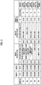
- Fig. 4 is a chart illustrating characteristics of a plurality of observation image samples corresponding to the observation image according to Example 1.
- a condition in which the image appearance recognition timing does not satisfy the range of the present invention is set as illustrated in Fig. 4 .
- Characteristic values of the density, the brightness, and the hue of each image at that time are also illustrated in Fig. 4 .
- the observation image changes as the development progresses.
- the observation image is clearly distinguished and recognized in a first stage and a second stage.
- An observation image is formed by creating an input image according to the following procedure, inputting the input image to the mono-sheet-type silver halide photographic photosensitive material for releasing and diffusion transfer of colorants, and performing development processing.
- the photosensitive material is a photosensitive material obtained by changing the photosensitive material according to Example 1 as follows.
- a liquid obtained by mixing coating compositions of a yellow color material layer, a magenta color material layer, and a cyan color material layer at a ratio of application amounts is divided into three equal parts and is applied such that the application amounts for the three layers are the same at a position of each color material layer of the three layers.
- the photosensitive material obtained in this way includes a red-sensitive emulsion layer (lower layer), a green-sensitive emulsion layer (middle layer), and a blue-sensitive emulsion layer (upper layer) in the order of proximity to the colorant receiving layer.
- the photosensitive material due to development of the photosensitive silver halide emulsion layer of each color, three colorants of yellow, magenta, and cyan are transferred at the same time. Thus, in a case where the photosensitive material is used, an almost black-and-white monochrome color image in which three colors are mixed is formed.
- Fig. 3 is a conceptual diagram illustrating an observation image according to Example 2.
- the observation image illustrated in Fig. 3 is in a form of "question” and "answer".
- step (1) the following steps are performed as step (1).
- a text information image of "What is the weather tomorrow?" is selected as an image for the image A
- an image of "cloud mark icon” is selected as an image for the image B.
- step (2) the following steps are performed as step (2).
- the layers to be developed are set such that conditions of the timings T1 and T2 required for the image appearance of the image A are satisfied, and an input image for the photosensitive material is created such that development is performed.
- the text information is expressed in bold in MSP Gothic font such that the following conditions are met.
- T2-T1 4 seconds D 1.50 (density of G) development layer upper layer/middle layer/lower layer
- the contributions of the three photosensitive layers in density are respectively set to 0.5. Specifically, a condition for imparting a density of 0.50 is determined by exposure and development of the lower layer. Thereafter, in addition to the condition, a condition for imparting a density of 1.0 is determined by exposure and development of the middle layer, and further, a condition for imparting a density of 1.5 is determined by exposure and development of the upper layer. In order, exposure conditions are set. In a case of forming an image by development processing of a plurality of layers in another sample, exposure conditions are similarly determined in order from the lower layer.
- step (3) the following steps are performed as step (3).
- the layers to be developed are set such that a condition of the timing T3 required for the image appearance of the image B is satisfied, and input image information for the photosensitive material is created such that development is performed.
- step (4) the following steps are performed as step (4).
- An input image for the photosensitive material is created by arranging and combining the image obtained in step (2) and the image obtained in step (3) such that the images have appropriate sizes and a positional relationship on the observation image screen.
- the input image obtained in this way is input to the mono-sheet-type silver halide photographic photosensitive material for releasing and diffusion transfer of colorants by using a multi light-emitting head in which light emitting diodes of three colors of R, G, and B are arranged in a main scanning direction according to a method described in JP1999-344772A ( JP-H11-344772A ).
- the developer is applied at 25°C and with a thickness of 62 ⁇ m, and development processing is performed.
- the input image information is converted into colorant image information, and thus an observation image sample 201 is formed.
- Fig. 5 is a chart illustrating characteristics of a plurality of observation image samples corresponding to the observation image according to Example 2.
- a condition in which the image appearance recognition timing does not satisfy the range of the present invention is set as illustrated in Fig. 5 .
- the density of each image at that time and the development layer are also illustrated in Fig. 5 .
- observation image samples 201 to 205 the appearance of the image after the start of development is observed, and whether or not the appearance of the image A and the appearance of the image B are clearly distinguished and recognized is evaluated by 10 examinees according to the same evaluation standard as in Example 1.
- Fig. 5 an average value by 10 persons is illustrated as an evaluation value.
- the observation image changes as the development progresses.
- a message that can be read from the observation image is clearly distinguished and recognized in a first stage and a second stage.
- An observation image is formed by creating an input image according to the following procedure, inputting the input image to the mono-sheet-type silver halide photographic photosensitive material for releasing and diffusion transfer of colorants, and performing development processing.
- the photosensitive material As the photosensitive material, the same photosensitive material as the photosensitive material used in Example 1 is used.
- the base image is an image in which a silhouette of a Japanese temple building appears against a background of cherry blossoms in full bloom.
- step (1) The following steps are first performed on the base image as step (1).
- a portion of "a silhouette of a Japanese temple building” is selected as an image region for the image A, and a portion of "cherry blossoms in full bloom” is selected as an image region for the image B.
- the images which are to be used for the image A and the image B are determined.
- step (2) the following steps are performed as step (2).
- characteristic values of the density, the brightness, and the hue of the final observation image are set such that conditions of the timings T1 and T2 required for the image appearance of the image A are satisfied.
- An input image for the photosensitive material is created such that the set final image density is expressed by the photosensitive material.
- the base image has a slightly brownish gray color in which L* is 58.
- the base image has a dark gray color in which L* is 21.
- step (3) the following steps are performed as step (3).
- characteristic values of the density, the brightness, and the hue of the final observation image are set such that a condition of the timing T3 required for the image appearance of the image B is satisfied.
- An input image for the photosensitive material is created such that the set final image density is expressed by the photosensitive material.
- the base image has a clear pink color in which L* is 60.
- the base image has a color in which L* is 65.
- step (4) the following steps are performed as step (4).
- An input image for the photosensitive material is created by recombining the image obtained in step (2) and the image obtained in step (3).
- Fig. 6 is a chart illustrating characteristics of a plurality of observation image samples corresponding to the observation image according to Example 3.
- the input image obtained in this way is input to the mono-sheet-type silver halide photographic photosensitive material for releasing and diffusion transfer of colorants, the photosensitive material being an auto-positive photosensitive material, by using a multi light-emitting head in which light emitting diodes of three colors of R, G, and B are arranged in a main scanning direction according to a method described in JP1999-344772A ( JP-H11-344772A ).
- the developer is applied at 25°C, and development processing is performed.
- the input image information is converted into colorant image information, and thus an observation image sample 301 is formed. Characteristic values of the density, the hue, and the brightness of each image at that time are also illustrated in Fig. 6 .
- An observation image sample 302 is formed in the same manner except that the base image is used as it is as an input image. Characteristic values of the density, the hue, and the brightness of each image at that time are also illustrated in Fig. 6 .
- the observation image changes as the development progresses, and thus, the observation image is clearly distinguished and recognized in a first stage and a second stage.
- steps (1) to (4) are sequentially performed.
- the formation of the image is determined in advance, and the image is mapped to the color gamut satisfying the conditions of the image A and the image B. Therefore, these steps can be performed at the same time.
- a template is used as the original image, and the image information includes a text and an image.
- the images of the portions (a) to (e) and text information are prepared.
- the print software for image appearance recognition speed control is started, and the images are transmitted to a personal computer (PC).
- the image of the portion (c) related to the question is used for the image A, and the images of the portions (d) and (e) related to the answer are used for the image B.
- a set of the images of the portions (a) to (e) can be used as one template for a quiz-type image configuration.
- the density, the brightness, and the hue of each image are mapped such that the image A and the image B satisfy the image appearance recognition timings, and the image information of each image is temporarily determined. Based on the temporarily determined image information, a demo moving image of the appearance of the observation image in a case where the observation image is obtained from the photosensitive material may be displayed.
- the image of the portion (e) has a later appearance timing than those of the other images.
- the input image for output is transmitted from the PC to an instant photo printer.
- the printer converts the input image into exposure data and exposes the photosensitive material. Subsequently, the photosensitive material is extruded from the printer, and at that time, a development treatment liquid is applied on the photosensitive material.
- the user observes a process of formation of an image on the observation surface of the photosensitive material.
- An input image is created according to the following procedure with a purpose of forming an observation image having a pattern similar to pattern of the observation image sample 301 according to Example 3. Except that, the observation image is formed and evaluated in the same manner as the formation of the observation image sample 301 according to Example 3.
- an input image is created by providing a large liquid crystal display in a background of a wooden panel, preparing capturing environments, preparing a subject, and capturing the subject.
- step (1) the following steps are performed as step (1).
- a portion of "a silhouette of a Japanese temple building” is selected as an image region for the image A, and a portion of "cherry blossoms in full bloom” is selected as an image region for the image B.
- the image regions which are to be used for the image A and the image B are determined.
- step (2) the following steps are performed as step (2).
- a wooden panel representing a silhouette of the Japanese temple building is created.
- the wooden panel is colored and illuminated as appropriate such that the appearance recognition timing of the image satisfies the condition of the image A.
- step (3) the following steps are performed as step (3).
- the portion of "cherry blossoms in full bloom” is displayed on a liquid crystal display and the hue, the density, and the brightness of the image are adjusted such that the appearance recognition timing of the image satisfies the condition of the image B.
- step (4) the following steps are performed as step (4).
- the liquid crystal display prepared in step (3) is appropriately disposed in the background of the wooden panel provided in step (2), fine adjustment such as illumination is performed, and conditions of the final subject to be captured are determined.
- the subject prepared in this way is captured by a digital camera, and a captured image is used as an input image.
- An image is formed and evaluated according to the method by using the created input image.
- the observation image changes as the development progresses. Therefore, the observation image is clearly distinguished and recognized in a first stage and a second stage.
- the series of processing can be easily performed by a single smartphone.
- the observation image is an image obtained by diffusing and transferring a solid-dispersed anionic colorant into a colorant receiving layer by a treatment using an alkaline liquid and immobilizing the anionic colorant in the colorant receiving layer, the observation image being drawn using the anionic colorant in a plurality of layer regions having different distances from the colorant receiving layer.
- step (2) and step (3) of creating the first drawing condition and the second drawing condition for drawing and forming an image pattern by using the precursor of the image forming material a drawing condition for drawing the image pattern using the anionic colorant in the plurality of regions (first image region and second image region) having different distances from the colorant receiving layer is created.
- the "chemical reaction" for forming an observation image by causing a chemical reaction to progress on the precursor is a treatment using an alkaline liquid.
- An amount of a colorant per unit area that is released from a solid-dispersed-colorant-containing layer closest to the colorant receiving layer in the highest density portion of the image A of the first image region is greater than an amount of a colorant per unit area that is released from the solid-dispersed-colorant-containing layer in the highest density portion of the image B of the second image region.
- the solid-dispersed anionic colorant may be in a solid state or an amorphous state at room temperature, and have an equivalent sphere diameter of approximately 0.05 ⁇ m to 1.0 ⁇ m.
- the solid-dispersed anionic colorant has such a size, and thus, in a solid-dispersed state, diffusion of molecules in a medium is prevented.
- the materials described in JP3619288B , JP3545680B , JP3264587B , and JP1994-148802A JP-H6-148802A ) may be used.
- a solid-dispersed anionic colorant a compound 1-1, a combined colorant (1), and a combined colorant (2) exemplified in JP3619288B , colorants 1 and 11 exemplified in JP3545680B , and colorants 1, 4, 5, 6, and 20 exemplified in JP3264587B may be used.
- a diffusion rate may be adjusted by a molecular weight of the colorant, a hydrophilicity, a hydrophobicity, a mother nucleus structure, and the like.
- a diffusion distance to the colorant receiving layer may be adjusted by drawing an image using the solid-dispersed colorant at a plurality of positions having different distances from the colorant receiving layer.
- the diffusion distance may be adjusted by providing, using a binder such as gelatin, on a surface on which initial drawing is performed using the solid-dispersed colorant, an interlayer which has a certain thickness or intentionally different thicknesses depending on the region, and further performing, on a front surface of the interlayer, second drawing using the solid-dispersed colorant.
- the diffusion distance may be adjusted by adjusting the thickness of the interlayer.
- a plurality of interlayers that can be used for adjusting the diffusion distance may be provided, and drawing may be performed on a front surface of each of the plurality of interlayers using the solid-dispersed colorant.
- a plurality of solid-dispersed colorants having different colors may be used.
- a rate at which the colorant is dissolved from the solid-dispersed state to a monomolecular state may be adjusted by a particle size of the solid-dispersed colorant. That is, since dissociation and dissolution of the colorant occur on front surfaces of the particles, by reducing the particle size, a front surface area per unit colorant amount can be increased. Thus, a dissolution rate can be increased. In addition, the dissolution rate can be controlled by adding an adsorptive substance to the particle surface.
- an interlayer having the same composition as a composition of a third layer is provided as a fifth layer such that the gelatin coating amount is 0.29 g/m 2 .
- the image A of the first image region is drawn by an ink jet apparatus using the solid-dispersed colorant (the compound 1-1 exemplified in JP3619288B ).
- an interlayer having the same composition as a composition of the third layer is provided such that the gelatin coating amount is 2.50 g/m 2 .
- the image B of the second image region is drawn by an ink jet apparatus using the solid-dispersed colorant.
- an interlayer having the same composition as a composition of the third layer is provided such that the gelatin coating amount is 2.50 g/m 2 .
- a container that can be broken by pressure is filled with an alkaline treatment liquid from which potassium sulfite is removed, and a mono-sheet-type material for releasing and diffusion transfer of colorants is formed according to the method described in JP1995-159931A ( JP-H7-159931A ).
- the alkaline treatment liquid is applied at 25°C with a thickness of 62 ⁇ m. Thereafter, the appearance of the image is observed. The image A of the first image region appears first, and the image B of the second image region appears later.
- the observation image is formed as a colored colorant image by drawing, on the support, the image pattern using an ink composition containing an oxidative coloring colorant and a reducing agent which is oxidized by oxygen and oxidizing the reducing agent and the colorant by oxygen in the atmosphere.
- step (2) and step (3) of creating the first drawing condition and the second drawing condition for drawing and forming an image pattern using a precursor of the image forming material compositions of the ink composition and drawing conditions are created. Further, the "chemical reaction" for forming an observation image by causing a chemical reaction to progress on the precursor is oxidation by oxygen in the atmosphere.
- Drawing is performed such that the image A of the first image region has a reducing activity lower than a reducing activity of the image B of the second image region.
- Examples of the oxidative coloring colorant of the precursor of the image forming material according to the present embodiment include a material of which the color is changed from substantially colorless to a colored color by oxidation, and a material of which the color is changed to another color by oxidation.
- the precursor of the image forming material may be inconspicuous to some extent.
- whiteness of the support can be increased.
- the density of the oxidative coloring colorant in a visible region is doubled or more, and more preferably three times or more by oxidation.
- the density in the visible region represents a total value of the densities of B, G, and R, and represents the density measured under a filter condition of status A in a state where a D65 light source is used.
- a material known as a leuco colorant may be used as such a material.
- the leuco colorant that can be used in the present embodiment include an indian aniline leuco colorant, an indamine leuco colorant, a triphenylmethane leuco colorant, a triarylmethane leuco colorant, a styryl leuco colorant, an N-acyloxazine leuco colorant, an N-acylthiazine leuco colorant, an N-acyldiazine leuco colorant, a xanthene leuco colorant, and the like.
- a colorant of which the color changes by redox a methylene blue, a neumethylene blue, a phenosafranin, a laus violet, a methylene green, a neutral red, an indigo carmine, an acid red, a safranin T, a capri blue, a nile blue, a diphenylamine, a xylene cyanol, a nitrodiphenylamine, a ferroin, an N-phenylanthranyl acid, and the like may be used. More preferably, a colorant such as a methylene blue or a phenosafranin that becomes colorless in a reduced state may be used.
- an inorganic material or a metal complex material is used.
- the inorganic material for example, NiO (nickel oxide), Cr 2 O 3 (chromium (III) oxide), MnO 2 (manganese dioxide), or CoO (cobalt oxide) is used.
- the metal complex material for example, a ferrocene, a Prussian blue, or a tungsten oxalic acid complex is used.
- an observation image is formed by oxidation of the precursor of the image forming material.
- the oxidation method may be roughly classified into the following two methods.
- a method in which oxidation is promoted by oxygen in the atmosphere in the vicinity of the image forming material and a method in which an oxidative material is present in the vicinity of the image forming material and oxidation is promoted by a chemical reaction with the oxidative material may be used.
- oxidation using oxygen in the air may be used.
- a method of controlling the oxidation rate of the precursor of the image forming material on the support and controlling the rate of the image appearance a method of delaying an oxidation reaction by adjusting an amount and a type of a reducing compound that delays oxidation by oxygen in the atmosphere may be used.
- dihydroxybenzenes for example, hydroquinone, hydroquinone monosulfonate
- 3-pyrazoridones for example, 1-phenyl-3-pyrazolidone, 1-phenyl-4-methyl-4-hydroxymethyl-3-pyrazolidone
- aminophenols for example, N-methyl-p-aminophenol, N-methyl-3-methyl-p-aminophenol
- ascorbic acid and isomers and derivatives of ascorbic acid may be used alone or in combination.
- ascorbic acid More preferably, ascorbic acid, hydroquinone potassium monosulfonate, or sodium hydroquinone monosulfonate may be used.
- sodium sulfite, hydroxylamines, saccharides, o-hydroxyketones, or hydrazines may be used as a reducing agent or a retaining agent for the reducing agent.
- saccharides may be used, and rutin and derivatives of the rutin known as flavonoid compounds may be used.
- reducing compounds are allowed to coexist with the precursor of the image forming material.
- an ink composition that is kept in a state where oxidation does not proceed is prepared, and drawing may be performed on the support using the ink composition.
- the method of controlling the oxidation rate of the precursor of the image forming material by changing the reducing activity for each image region can be achieved by properly using, for each image region, a plurality of types of the ink compositions in which the amount and the type of the reducing compound in the ink composition are changed.
- oxidizing agent supplied to the support or change the amount of catalyst for changing the activity of the oxidation reaction progress.
- these components can be changed and applied for each image region on the support.
- an oxidizing agent preferably, hydrogen peroxide (water) may be used because hydrogen peroxide does not leave colored substances or dangerous substances after the reaction even in a case where hydrogen peroxide remains on the support.
- pH may be adjusted for each image region by using an acid or an alkali.
- the following example is an example in which a difference in the air oxidation rate of the oxidative coloring colorant is given by changing the amount of the reducing agent that prevents oxidation by air coexisting with the colorant.
- Drawing is performed on a paper support by an ink jet apparatus using two types of inks including an ink for an image having a high image appearance speed and an ink for an image having a low image appearance speed.
- an ink obtained by adding ascorbic acid to a methylene blue aqueous solution until a color of the oxidant disappeared and further adding ascorbic acid having the same mass as the mass of the ascorbic acid required for disappearance is used.
- an ink obtained by adding ascorbic acid in an amount three times as much as the ascorbic acid used in the ink for the image A is used. In a case of observing the drawn image indoors, after the image A appears, the image B appears, and two regions having different image appearance speeds are observed.
- the observation image is formed as an image of metallic silver fine particles by reducing an image, which is drawn on the support using an ink composition containing silver ions, by a reducing agent.
- step (2) and step (3) of creating the first drawing condition and the second drawing condition for drawing and forming an image pattern using a precursor of the image forming material compositions of the ink composition for imparting a reducing activity and drawing conditions are created. Further, the "chemical reaction" for forming an observation image by causing a chemical reaction to progress on the precursor is reduction.
- Drawing is performed such that the image A of the first image region has a reducing activity higher than a reducing activity of the image B of the second image region.
- Examples of an ink material containing silver ions according to the present embodiment include a silver nitrate aqueous solution. Further, a Tollens' reagent prepared by adding aqueous ammonia to a silver nitrate aqueous solution may also be used.
- the support is not colored immediately after drawing is performed on the support.
- the reducing agent mentioned in the fourth embodiment of the image forming method may be used. More preferably, ascorbic acid, hydroquinone potassium monosulfonate, or sodium hydroquinone monosulfonate may be used. Further, in a case where a Tollens' reagent is used, preferably, a reducing saccharide may be used.
- the method of changing the reducing activity for each image region can be achieved by properly using, for each image region, a plurality of types of the ink compositions in which the amount and the type of the reducing compound in the ink composition are changed, or by changing an application amount of the ink composition.
- a timing for application to the support a timing before the ink composition containing the precursor of the image forming material is applied, a timing when the ink composition is applied, or a timing after the ink composition is applied may be used.
- a timing for mixing the silver ion and the reducing agent in a liquid state is long, the reaction progress rate is high. From this point, by increasing the absolute amount of water application or using a moisturizer for delaying water volatilization, the reducing activity can be increased.
- the following example is an example of imparting a difference in image appearance recognition timing by changing the reducing activity for each image region in a case of reducing the silver ions of silver nitrate and changing a color of silver nitrate to a black color.
- An ink is prepared using ascorbic acid as the reducing agent and one type of flavonoid rutin as a stabilizer for ascorbic acid.
- the application amount of ascorbic acid is adjusted such that the amount of ascorbic acid applied to the image A, which appears relatively earlier, is greater than the amount of ascorbic acid applied to the image B. In this way, two regions having different reducing activities are formed.
- an observation image is drawn on a paper support containing a reducing agent by an ink jet apparatus.
- the drawn observation image is observed.
- an image of gradually blackened silver is obtained from a white background.
- the image B appears.
- two regions having different image appearance speeds are observed.
- the fourth embodiment and the fifth embodiment of the image forming method may be used in combination.
- the silver nitrate ink of the fifth embodiment may be used for the image A
- the methylene blue ink of the fourth embodiment may be used for the image B.
- a smartphone As the image forming apparatus according to the present invention, a smartphone, a digital camera, a mobile information terminal with a camera, a game device, a tablet terminal, or the like may be used.
- Fig. 7 is a diagram illustrating an appearance of a smartphone as an embodiment of an image forming apparatus according to the present invention.
- the smartphone 100 illustrated in Fig. 7 includes a flat plate housing 102, a display panel 121 as a display unit that is provided on one surface of the housing 102, and a display input unit 120 in which an operation panel 122 as an input unit is integrated. Further, the housing 102 includes a speaker 131, a microphone 132, an operation unit 140, and a camera unit 141.
- Fig. 8 is a block diagram illustrating an internal configuration of the smartphone illustrated in Fig. 7 .
- a wireless communication unit 110 As illustrated in Fig. 8 , as main components of the smartphone 100, a wireless communication unit 110, the display input unit 120, a call unit 130, the operation unit 140, the camera unit 141, a storage unit 150, an external input and output unit (output unit) 160, a global positioning system (GPS) receiving unit 170, a motion sensor unit 180, a power supply unit 190, and a main control unit 101 are provided. Further, as a main function of the smartphone 100, the smartphone 100 has a wireless communication function of performing mobile wireless communication via a base station apparatus and a mobile communication network.
- GPS global positioning system
- the wireless communication unit 110 performs wireless communication with the base station apparatus connected to a mobile communication network according to an instruction of the main control unit 101.
- the wireless communication unit 110 transmits and receives various file data such as voice data and image data, e-mail data, and the like, and receives web data, streaming data, and the like by using wireless communication.
- the display input unit 120 is a so-called touch panel including the operation panel 122 provided on a screen of the display panel 121. Under a control of the main control unit 101, the display input unit 120 visually informs the user of information by displaying images (still images and moving images), text information, and the like, and detects a user's operation on the displayed information.
- the operation panel 122 is also referred to as a touch panel for convenience.
- the display panel 121 uses a liquid crystal display (LCD), an organic electro-luminescence display (OELD), or the like as a display device.
- the operation panel 122 is a device that is provided to allow the user to visually recognize an image displayed on a display surface of the display panel 121 and detects one or a plurality of coordinates obtained by a finger operation or a stylus operation by the user. In a case where the device is operated by a finger operation or a stylus operation by the user, the operation panel 122 outputs a detection signal generated by the operation to the main control unit 101. Next, the main control unit 101 detects an operation position (coordinate) on the display panel 121 based on the received detection signal.
- the display panel 121 and the operation panel 122 of the smartphone 100 are integrated as one body and are provided as the display input unit 120.
- the operation panel 122 is disposed such that the display panel 121 is completely covered.
- the operation panel 122 may have a function of detecting an operation of a user even in a region outside the display panel 121.
- the call unit 130 includes a speaker 131 and a microphone 132, and is a unit that converts a user's voice input through the microphone 132 into voice data which can be processed by the main control unit 101 and outputs the voice data to the main control unit 101 and that decodes voice data received by the wireless communication unit 110 or the external input and output unit 160 and outputs the voice data from the speaker 131.
- the speaker 131 and the microphone 132 may be provided on the same surface as the surface on which the display input unit 120 is provided.
- the operation unit 140 is a hardware key using a key switch and the like, and receives an instruction from the user.
- the operation unit 140 is provided on a side surface of the housing 102 of the smartphone 100, and is a push button type switch that is turned on when pressed by a finger or the like and is turned off by a restoring force of a spring or the like when the finger is released.
- the storage unit 150 is a unit that stores a control program and control data of the main control unit 101, various application software including an image forming program according to the present invention, address data associated with a name and a telephone number of a communication partner, transmitted/received e-mail data, web data downloaded by web browsing, and downloaded content data and that temporarily stores streaming data and the like.
- the storage unit 150 includes an internal storage unit 151 that is built in the smartphone and an external storage unit 152 including an attachable and detachable external memory slot.
- Each of the internal storage unit 151 and the external storage unit 152 included in the storage unit 150 is realized by using a storage medium such as a flash memory, a hard disk, a MultiMediaCard micro memory, a card type memory, a random access memory (RAM), and a read only memory (ROM).
- a storage medium such as a flash memory, a hard disk, a MultiMediaCard micro memory, a card type memory, a random access memory (RAM), and a read only memory (ROM).
- the external input and output unit 160 serves as an interface between the smartphone 100 and all external apparatuses connected to the smartphone 100, and directly or indirectly connects the smartphone 100 to another external apparatus by communication (for example, a USB (universal serial bus), IEEE 1394, or the like) or by a network (for example, the Internet, a wireless local area network (LAN), Bluetooth (registered trademark), or the like).
- communication for example, a USB (universal serial bus), IEEE 1394, or the like
- a network for example, the Internet, a wireless local area network (LAN), Bluetooth (registered trademark), or the like.
- Examples of the external apparatus connected to the smartphone 100 include, for example, a memory card or a subscriber identity module (SIM) card/user identity module (UIM) card connected via a card socket, a printer (including a printer for outputting an observation image according to the present invention) connected in a wired/wireless manner, a smartphone, a personal computer, and earphones.
- the external input and output unit 160 may be configured to transmit data transmitted from such an external apparatus to each component in the smartphone 100, or transmit data in the smartphone 100 to the external apparatus.
- the GPS receiving unit 170 receives GPS signals transmitted from GPS satellites ST1, ST2 to STn according to an instruction of the main control unit 101, executes positioning calculation processing based on the received plurality of GPS signals, and acquires position information (GPS information) specified by a latitude, a longitude, and an altitude of the smartphone 100.
- GPS information position information
- the motion sensor unit 180 includes, for example, a three-axis acceleration sensor, and detects a physical movement of the smartphone 100 according to an instruction of the main control unit 101. By detecting the physical movement of the smartphone 100, a movement direction and acceleration of the smartphone 100 are detected. The result of the detection is output to the main control unit 101.
- the power supply unit 190 supplies electric power stored in a battery (not illustrated) to each unit of the smartphone 100 according to an instruction of the main control unit 101.
- the main control unit 101 includes a microprocessor, operates according to a control program and control data stored in the storage unit 150, and collectively controls each unit of the smartphone 100.
- the main control unit 101 has a mobile communication control function for controlling each unit of a communication system and an application processing function to perform voice communication and data communication via the wireless communication unit 110.
- the application processing function is realized by operating the main control unit 101 according to application software stored in the storage unit 150.
- Examples of the application processing function include, for example, an infrared communication function of performing data communication with an opposite apparatus by controlling the external input and output unit 160, an e-mail function of transmitting and receiving an e-mail, a web browsing function of browsing a web page, and an image forming function according to the present invention.
- the main control unit 101 has an image processing function such as displaying a video on the display input unit 120 based on image data (a still image or moving image data) such as received data or downloaded streaming data.
- the image processing function refers to a function in which the main control unit 101 decodes the image data, performs image processing on the decoding result, and displays an image obtained by the image processing on the display input unit 120.
- the main control unit 101 executes a display control for the display panel 121 and an operation detection control for detecting an operation of a user via the operation unit 140 and the operation panel 122.
- the main control unit 101 By executing the display control, the main control unit 101 displays an icon for starting the application software, a software key such as a scroll bar, or a window for transmitting an e-mail.
- the main control unit 101 detects an operation of the user via the operation unit 140, receives an operation on the icon and a character string input in an input field of the window via the operation panel 122, or receives a scroll request for a display image via the scroll bar.
- the camera unit 141 may convert image data obtained by image capturing into, for example, compressed image data such as joint photographic experts group (JPEG), and record the image data in the storage unit 150 or output the image data via the external input and output unit 160 or the wireless communication unit 110.
- JPEG joint photographic experts group
- the camera unit 141 is provided on the same surface as the display input unit 120.
- a position of the camera unit 141 is not limited thereto, and the camera unit 141 may be provided on a rear surface of the housing 102 instead of a front surface of the housing 102 on which the display input unit 120 is provided.
- a plurality of camera units 141 may be provided on the housing 102.
- the camera unit 141 may be used for various functions of the smartphone 100.
- the image acquired by the camera unit 141 may be used as an original image which is to be used for forming the observation image according to the present invention.
- text information which is input by the operation unit 140, position information acquired by the GPS receiving unit 170, and voice information acquired by the microphone 132 may be recorded in the storage unit 150 or may be output via the external input and output unit 160 and the wireless communication unit 110.
- the smartphone 100 having the configuration has the following functions in a case where the main control unit 101 executes an image forming program (print application software for image appearance timing control) according to the present invention, the program being downloaded from a server that is not illustrated.
- an image forming program print application software for image appearance timing control
- a photographic image is captured by the smartphone 100.
- the print application software for image appearance timing control (hereinafter, referred to as "the application") is started and the photographic image is transmitted to the application.
- the original photographic image captured by the smartphone 100 is displayed.
- the subject in the photographic image is recognized and the photographic image is divided into segments by the application. According to patterns obtained by learning the divided segments in advance, approximately 6 patterns of combination candidates indicating which part of the photographic image is to be used for the image A and the image B are created. Among the patterns, two patterns having a high frequency of adoption are presented.
- the user selects a pattern different from the patterns proposed by the application two of the following candidates are presented, and the user selects a desired pattern from the presented patterns.
- the user is asked to select images to be used for the image A and the image B from the images obtained by segmenting the image regions of the captured image.
- a version 1 of a final observation image is created by mapping the selected pattern with chromaticity points of an image in each segment such that the image appearance speed is satisfied.
- a demo moving image of appearance is displayed.
- a title may be added to the output image, or template information may be inserted into the output image.
- Information of the additional portion may be appropriately selected for the image A or the image B.
- An input image is completed by combining the image A and the image B and adding an image title as necessary.
- the input image is transmitted from the smartphone 100 to an instant photo printer.
- the printer converts the input image into exposure data and exposes the photosensitive material. Subsequently, the photosensitive material is extruded from the printer, and at that time, a development treatment liquid is applied on the photosensitive material.
- the user observes a process of formation of an image on the observation surface of the photosensitive material.
- the hardware that realizes the image forming apparatus according to the present invention may be configured by various processors.
- the various processors include a central processing unit (CPU) which is a general-purpose processor that functions as various processing units by executing a program, a programmable logic device (PLD) such as a field programmable gate array (FPGA) which is a processor capable of changing a circuit configuration after manufacture, a dedicated electric circuit such as an application specific integrated circuit (ASIC) which is a processor having a circuit configuration specifically designed to execute specific processing, and the like.
- CPU central processing unit
- PLD programmable logic device
- FPGA field programmable gate array
- ASIC application specific integrated circuit
- One processing unit of the image forming apparatus may be configured by one of these various processors, or may be configured by two or more processors having the same type or different types.
- one processing unit may be configured by a combination of a plurality of FPGAs or a combination of a CPU and an FPGA.
- the plurality of processing units may be configured by one processor.
- the plurality of processing units are configured by one processor, firstly, as represented by a computer such as a client and a server, a form in which one processor is configured by a combination of one or more CPUs and software and the processor functions as the plurality of processing units may be adopted.
- SoC system on chip
- IC integrated circuit
- the present invention includes an image forming program, which causes a computer to function as an image forming apparatus according to the present invention by being installed in the computer, and a storage medium recording the image forming program.
Landscapes
- Physics & Mathematics (AREA)
- General Physics & Mathematics (AREA)
- Chemical & Material Sciences (AREA)
- Chemical Kinetics & Catalysis (AREA)
- Engineering & Computer Science (AREA)
- Materials Engineering (AREA)
- Facsimile Image Signal Circuits (AREA)
- Silver Salt Photography Or Processing Solution Therefor (AREA)
- Photographic Developing Apparatuses (AREA)
Applications Claiming Priority (1)
| Application Number | Priority Date | Filing Date | Title |
|---|---|---|---|
| JP2020103263A JP7413156B2 (ja) | 2020-06-15 | 2020-06-15 | 画像形成方法、装置及びプログラム |
Publications (1)
| Publication Number | Publication Date |
|---|---|
| EP3926399A1 true EP3926399A1 (en) | 2021-12-22 |
Family
ID=76392169
Family Applications (1)
| Application Number | Title | Priority Date | Filing Date |
|---|---|---|---|
| EP21178814.6A Pending EP3926399A1 (en) | 2020-06-15 | 2021-06-10 | Image forming method, image forming apparatus, and image forming program |
Country Status (4)
| Country | Link |
|---|---|
| US (1) | US20210389660A1 (https=) |
| EP (1) | EP3926399A1 (https=) |
| JP (1) | JP7413156B2 (https=) |
| CN (1) | CN113805424A (https=) |
Citations (12)
| Publication number | Priority date | Publication date | Assignee | Title |
|---|---|---|---|---|
| DE2529488A1 (de) * | 1975-07-02 | 1977-01-27 | Agfa Gevaert Ag | Photographisches material fuer das farbstoffdiffusionsuebertragungsverfahren |
| JPH06148802A (ja) | 1992-11-05 | 1994-05-27 | Fuji Photo Film Co Ltd | 写真用微粒子固体分散物の調製方法 |
| JPH07159931A (ja) | 1993-12-02 | 1995-06-23 | Fuji Photo Film Co Ltd | インスタントフイルムパック及びカメラ |
| US5957458A (en) * | 1997-03-03 | 1999-09-28 | Temtec, Inc. | Substrate with hidden images and method of making such images appear |
| JPH11344772A (ja) | 1998-03-16 | 1999-12-14 | Fuji Photo Film Co Ltd | インスタントプリンタ及びインスタントフイルム |
| JP2000112096A (ja) | 1998-10-08 | 2000-04-21 | Fuji Photo Film Co Ltd | カラー拡散転写感光材料 |
| JP3264587B2 (ja) | 1994-08-09 | 2002-03-11 | 富士写真フイルム株式会社 | ハロゲン化銀写真感光材料 |
| JP3545680B2 (ja) | 1993-03-24 | 2004-07-21 | 富士写真フイルム株式会社 | 染料の固体微粒子分散物 |
| JP3619288B2 (ja) | 1995-06-22 | 2005-02-09 | 富士写真フイルム株式会社 | カラー画像形成方法 |
| JP2006113291A (ja) | 2004-10-14 | 2006-04-27 | Fuji Photo Film Co Ltd | カラー拡散転写フイルムユニット及びカラー拡散転写フイルムユニットを用いた画像形成方法 |
| US20160059610A1 (en) * | 2014-08-27 | 2016-03-03 | Elwha Llc | Time-dependent identification systems, methods, and uses thereof |
| US20160063368A1 (en) * | 2014-08-27 | 2016-03-03 | Elwha Llc | Time-dependent identification systems, methods, and uses thereof |
Family Cites Families (8)
| Publication number | Priority date | Publication date | Assignee | Title |
|---|---|---|---|---|
| US3120992A (en) * | 1960-06-16 | 1964-02-11 | Hollingsworth R Lee | Automobile traffic surveillance apparatus and speed measurement equipment |
| US5707680A (en) * | 1996-01-02 | 1998-01-13 | Moore; Steven Jerome | Method for reducing invalid acceptances of expired printed offers and end-consumer re-distribution of printed works |
| US5571656A (en) * | 1996-02-09 | 1996-11-05 | Polroid Corporation | Multicolor diffusion transfer photographic film elements |
| US5946031A (en) * | 1996-10-22 | 1999-08-31 | Polaroid Corporation | Electronic still camera with printing capability |
| EP1011988A4 (en) * | 1997-03-03 | 2006-02-08 | Brady Worldwide Inc | SUBSTRATE CONTAINING HIDDEN IMAGES AND METHOD OF APPEARING THESE IMAGES |
| US20110310142A1 (en) * | 2006-10-04 | 2011-12-22 | Yongyong Xu | Time limited printing method and device |
| TWI515508B (zh) * | 2013-12-06 | 2016-01-01 | Japan Photo Finish Co Ltd | The method of judging the order of the game and its device |
| US10012864B2 (en) * | 2015-04-17 | 2018-07-03 | Travis KNIFFIN | Apparatus, system, and method for developing photos from digital images |
-
2020
- 2020-06-15 JP JP2020103263A patent/JP7413156B2/ja active Active
-
2021
- 2021-06-10 EP EP21178814.6A patent/EP3926399A1/en active Pending
- 2021-06-11 CN CN202110654002.2A patent/CN113805424A/zh active Pending
- 2021-06-14 US US17/346,982 patent/US20210389660A1/en active Pending
Patent Citations (12)
| Publication number | Priority date | Publication date | Assignee | Title |
|---|---|---|---|---|
| DE2529488A1 (de) * | 1975-07-02 | 1977-01-27 | Agfa Gevaert Ag | Photographisches material fuer das farbstoffdiffusionsuebertragungsverfahren |
| JPH06148802A (ja) | 1992-11-05 | 1994-05-27 | Fuji Photo Film Co Ltd | 写真用微粒子固体分散物の調製方法 |
| JP3545680B2 (ja) | 1993-03-24 | 2004-07-21 | 富士写真フイルム株式会社 | 染料の固体微粒子分散物 |
| JPH07159931A (ja) | 1993-12-02 | 1995-06-23 | Fuji Photo Film Co Ltd | インスタントフイルムパック及びカメラ |
| JP3264587B2 (ja) | 1994-08-09 | 2002-03-11 | 富士写真フイルム株式会社 | ハロゲン化銀写真感光材料 |
| JP3619288B2 (ja) | 1995-06-22 | 2005-02-09 | 富士写真フイルム株式会社 | カラー画像形成方法 |
| US5957458A (en) * | 1997-03-03 | 1999-09-28 | Temtec, Inc. | Substrate with hidden images and method of making such images appear |
| JPH11344772A (ja) | 1998-03-16 | 1999-12-14 | Fuji Photo Film Co Ltd | インスタントプリンタ及びインスタントフイルム |
| JP2000112096A (ja) | 1998-10-08 | 2000-04-21 | Fuji Photo Film Co Ltd | カラー拡散転写感光材料 |
| JP2006113291A (ja) | 2004-10-14 | 2006-04-27 | Fuji Photo Film Co Ltd | カラー拡散転写フイルムユニット及びカラー拡散転写フイルムユニットを用いた画像形成方法 |
| US20160059610A1 (en) * | 2014-08-27 | 2016-03-03 | Elwha Llc | Time-dependent identification systems, methods, and uses thereof |
| US20160063368A1 (en) * | 2014-08-27 | 2016-03-03 | Elwha Llc | Time-dependent identification systems, methods, and uses thereof |
Non-Patent Citations (1)
| Title |
|---|
| "Fine Imaging and Color Hard Copy", 1999, CORONA PUBLISHING CO., LTD., pages: 354 |
Also Published As
| Publication number | Publication date |
|---|---|
| JP7413156B2 (ja) | 2024-01-15 |
| CN113805424A (zh) | 2021-12-17 |
| JP2021196519A (ja) | 2021-12-27 |
| US20210389660A1 (en) | 2021-12-16 |
Similar Documents
| Publication | Publication Date | Title |
|---|---|---|
| EP1147722A1 (en) | Hair color advice system | |
| US11854310B2 (en) | Face liveness detection method and related apparatus | |
| US10682089B2 (en) | Information processing apparatus, information processing method, and program | |
| Balkenius et al. | Colour constancy in diurnal and nocturnal hawkmoths | |
| EP3203308A2 (en) | Display system, eyewear, and method for controlling display system | |
| CN108965692A (zh) | 贴纸设置方法及装置 | |
| EP3926399A1 (en) | Image forming method, image forming apparatus, and image forming program | |
| KR20210021499A (ko) | 검출 방법 및 검출 패드 | |
| US20220236190A1 (en) | Detection method and detection pad | |
| Yorzinski et al. | Sclera color in humans facilitates gaze perception during daytime and nighttime | |
| US12518479B2 (en) | Three-dimensional model reconstruction method, device, and storage medium | |
| US12430088B2 (en) | System, terminal, server, image display method, and program | |
| CN111773683A (zh) | 一种基于移动终端的文字显示方法及装置 | |
| Reeder et al. | Digital negatives with QuadToneRIP: demystifying QTR for photographers and printmakers | |
| Shapter | Are Photographs Truthful? Whence Veracity? | |
| Kashyap et al. | Colorimetric Based Glucose Detection with Machine Learning Approaches | |
| US4948709A (en) | Production of business cards and the like | |
| JP2021196519A5 (https=) | ||
| KR20200128844A (ko) | 유체에 포함된 타겟 물질을 검출하는 검출 패드 | |
| US6180324B1 (en) | Heat developable color photographic material and image-forming system using the same | |
| KR20200128841A (ko) | 채액에서 타겟 물질을 검출하는 방법 및 검출 패드 | |
| Brill | Camera color gamut: Spray‐painting the invisible definition | |
| Forrester | The effect of perceptual, conceptual, spatial, and sociocultural context on colour-emotion associations | |
| KR20250117863A (ko) | 디스플레이 장치 및 영상 처리 방법 | |
| KR20200128835A (ko) | 휴대단말을 이용한 채액 속의 타겟 검출방법 |
Legal Events
| Date | Code | Title | Description |
|---|---|---|---|
| PUAI | Public reference made under article 153(3) epc to a published international application that has entered the european phase |
Free format text: ORIGINAL CODE: 0009012 |
|
| STAA | Information on the status of an ep patent application or granted ep patent |
Free format text: STATUS: THE APPLICATION HAS BEEN PUBLISHED |
|
| AK | Designated contracting states |
Kind code of ref document: A1 Designated state(s): AL AT BE BG CH CY CZ DE DK EE ES FI FR GB GR HR HU IE IS IT LI LT LU LV MC MK MT NL NO PL PT RO RS SE SI SK SM TR |
|
| B565 | Issuance of search results under rule 164(2) epc |
Effective date: 20211109 |
|
| STAA | Information on the status of an ep patent application or granted ep patent |
Free format text: STATUS: REQUEST FOR EXAMINATION WAS MADE |
|
| 17P | Request for examination filed |
Effective date: 20220620 |
|
| RBV | Designated contracting states (corrected) |
Designated state(s): AL AT BE BG CH CY CZ DE DK EE ES FI FR GB GR HR HU IE IS IT LI LT LU LV MC MK MT NL NO PL PT RO RS SE SI SK SM TR |
|
| STAA | Information on the status of an ep patent application or granted ep patent |
Free format text: STATUS: EXAMINATION IS IN PROGRESS |
|
| 17Q | First examination report despatched |
Effective date: 20250527 |