EP3926319A1 - Leakage oil detection apparatus and leakage oil detection method - Google Patents
Leakage oil detection apparatus and leakage oil detection method Download PDFInfo
- Publication number
- EP3926319A1 EP3926319A1 EP19915211.7A EP19915211A EP3926319A1 EP 3926319 A1 EP3926319 A1 EP 3926319A1 EP 19915211 A EP19915211 A EP 19915211A EP 3926319 A1 EP3926319 A1 EP 3926319A1
- Authority
- EP
- European Patent Office
- Prior art keywords
- oil
- image
- leakage oil
- light
- leakage
- Prior art date
- Legal status (The legal status is an assumption and is not a legal conclusion. Google has not performed a legal analysis and makes no representation as to the accuracy of the status listed.)
- Granted
Links
Images


Classifications
-
- G—PHYSICS
- G01—MEASURING; TESTING
- G01M—TESTING STATIC OR DYNAMIC BALANCE OF MACHINES OR STRUCTURES; TESTING OF STRUCTURES OR APPARATUS, NOT OTHERWISE PROVIDED FOR
- G01M3/00—Investigating fluid-tightness of structures
- G01M3/02—Investigating fluid-tightness of structures by using fluid or vacuum
- G01M3/04—Investigating fluid-tightness of structures by using fluid or vacuum by detecting the presence of fluid at the leakage point
-
- G—PHYSICS
- G01—MEASURING; TESTING
- G01M—TESTING STATIC OR DYNAMIC BALANCE OF MACHINES OR STRUCTURES; TESTING OF STRUCTURES OR APPARATUS, NOT OTHERWISE PROVIDED FOR
- G01M3/00—Investigating fluid-tightness of structures
- G01M3/38—Investigating fluid-tightness of structures by using light
-
- G—PHYSICS
- G06—COMPUTING OR CALCULATING; COUNTING
- G06T—IMAGE DATA PROCESSING OR GENERATION, IN GENERAL
- G06T7/00—Image analysis
- G06T7/0002—Inspection of images, e.g. flaw detection
- G06T7/0004—Industrial image inspection
- G06T7/0008—Industrial image inspection checking presence/absence
-
- G—PHYSICS
- G06—COMPUTING OR CALCULATING; COUNTING
- G06T—IMAGE DATA PROCESSING OR GENERATION, IN GENERAL
- G06T2207/00—Indexing scheme for image analysis or image enhancement
- G06T2207/20—Special algorithmic details
- G06T2207/20081—Training; Learning
Definitions
- the present invention relates to a leakage oil detection device and a leakage oil detection method, and particularly to a leakage oil detection device and a leakage oil detection method suitable for leakage oil detection of an oil filled apparatus such as a transformer, a condenser, a hydraulic operation device of a gas insulated switchgear (GIS), a rectifier, a converter, and an inverter.
- an oil filled apparatus such as a transformer, a condenser, a hydraulic operation device of a gas insulated switchgear (GIS), a rectifier, a converter, and an inverter.
- GIS gas insulated switchgear
- PTL 1 describes a technique of detecting leakage oil by detecting fluorescence reflected by the leakage oil when ultraviolet light including an absorption wavelength of the leakage oil is irradiated to an object to be measured (an inspect target object such as a transformer), and more specifically, calculating the brightness and saturation of each pixel of a captured image by performing image processing on the pixels during ultraviolet light irradiation, creating a brightness-saturation graph and a brightness-saturation characteristic curve, and recognizing pixels deviated from the brightness-saturation characteristic curve by a predetermined value or more as a fluorescent spot, that is, a leakage oil spot.
- PTL 1 Although the technique described in PTL 1 is effective for detecting leakage oil in a period of time in which an illuminance is low, such as at night, when background noise due to daytime sunlight is large, a detection accuracy of the leakage oil decreases.
- the present invention has been made in view of the above facts, and an object of the present invention is to provide a leakage oil detection device and a leakage oil detection method capable of accurately detecting leakage oil when a background noise due to daytime sunlight is large.
- the present invention relates to "a leakage oil detection device configured to detect leakage oil in an oil filled apparatus, the leakage oil detection device including: a light source configured to irradiate the oil filled apparatus with light; an imaging device configured to capture an image of the oil filled apparatus; a control device configured to control operations of the light source and the imaging device; a storage device configured to store a captured image; an image processing device configured to process the stored image; and a display device configured to display a processing result, in which the light source and the imaging device are arranged in a manner of being capable of capturing specular reflection light from a surface of the oil filled apparatus as a target object, and the image processing device recognizes a brightest portion and a dark portion adjacent to the brightest portion on the captured image as leakage oil adhesion portions when a three-layer structure of luminance having bright portions having different luminances and a dark portion is observed in the image.”
- the present invention relates to "a leakage oil detection device configured to detect leakage oil in an oil filled apparatus, the leakage oil detection device including: a light source configured to irradiate the oil filled apparatus with light; an imaging device configured to capture an image of the oil filled apparatus; a control device configured to control operations of the light source and the imaging device; a storage device configured to store a captured image; an image processing device configured to process the stored image; and a display device configured to display a processing result, in which the light source and the imaging device are arranged in a manner of being capable of capturing specular reflection light from a surface of the oil filled apparatus as a target object, and the image processing device recognizes a bright portion in luminance as a leakage oil adhesion portion when the bright portion is observed inside a dark portion of the captured image at an end portion of the image.”
- the present invention relates to "a leakage oil detection method for detecting leakage oil of an oil filled apparatus by using an image obtained by irradiating the oil filled apparatus with light and capturing an image of the oil filled apparatus, the leakage oil detection method including: recognizing a brightest portion and a dark portion adjacent to the brightest portion on the captured image as leakage oil adhesion portions when a three-layer structure of luminance having bright portions having different luminances and a dark portion is observed in the image.”
- the present invention relates to "a leakage oil detection method for detecting leakage oil of an oil filled apparatus by using an image obtained by irradiating the oil filled apparatus with light and capturing an image of the oil filled apparatus, the leakage oil detection method including: recognizing a bright portion in luminance as a leakage oil adhesion portion when the bright portion is observed inside a dark portion of the captured image at an end portion of the image.”
- leakage oil can be accurately detected when a background noise due to daytime sunlight is large.
- a leakage oil detection device 100 and a leakage oil detection method according to the first embodiment of the present invention for inspecting oil adhering to a surface of an oil filled apparatus will be described with reference to FIGS. 1 to 3 .
- an oil filled transformer in a substation will be described as an example.
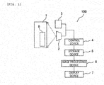
- FIG. 1 is a diagram showing a schematic configuration example of an inspection target object 1 and a leakage oil detection device 100 according to a first embodiment.
- the inspection target object 1 is an oil filled apparatus such as a transformer, a capacitor, a hydraulic operation device of a gas insulated switchgear (GIS), a rectifier, an inverter, or a converter.
- GIS gas insulated switchgear
- an oil filled transformer disposed in the substation will be described as the inspection target object 1.
- the leakage oil detection device 100 includes a light source 2, an imaging device 3, a control device 4 that controls the operations of the devices 2 and 3, a storage device 5 that stores captured images, an image processing device 6 that processes the stored images, and a display device 7 that displays processing results.
- the leakage oil detection device 100 captures an image of a leakage oil 8 adhering to a surface of the inspection target object 1, and finally displays an inspection result of the leakage oil on the display device 7.
- any lamp including visible light may be used as the light source 2.
- the imaging device 3 a general-purpose product such as a digital camera or a monitoring camera that captures visible light can be used.
- the light source 2 which is a visible light source, is used, and the specular reflected light of the oil is captured by the imaging device 3, and thereby minute leakage oil is detected.
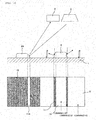
- FIG. 2 is a diagram for explaining a concept of a leakage oil detection method according to the present invention. Only a specular reflection portion of the target object surface is shown. An upper part of FIG. 2 shows the surface of the target object 1 to which the leakage oil 8 is attached, and a lower part of FIG. 2 shows luminances of parts in the captured image of the surface of the target object 1.
- the light source 2 and the imaging device 3 are arranged in a manner of being capable to capture specular reflected light from the surface of the target object 1.
- the light source 2 and the imaging device 3 are installed at positions in a direction orthogonal to the surface of the target object 1, and the reflected light from the surface of the target object 1 is imaged by the imaging device 3. Accordingly, when the oil 8 adheres to the portion of the specular reflected light, the specular reflected light from the oil 8 is also captured in the same manner.
- an oil surface specular reflected light portion 10 corresponding to the outermost surface 8a of the oil 8 and a target object surface specular reflected light portion 9 corresponding to the surface to which the oil is not attached are bright, but an oil surface specular reflected light portion 11 corresponding to the boundary portion 8b between the oil and the target object is dark.
- the oil surface specular reflected light portion 10 When comparing the oil surface specular reflected light portion 10 and the target object surface specular reflected light portion 9, the oil surface specular reflected light portion 10 is observed as an image brighter than the target object surface specular reflected light portion 9 because a reflectance of the oil 8 with respect to visible light is higher than a reflectance of the surface of the target object 1.
- the luminance of the oil surface specularly reflected light portion 10 is K1
- the luminance of the boundary portion 11 between the oil and the target object is K2
- the luminance of the target object surface specular reflected light generating portion 9 is K3.
- the oil surface specular reflected portion 10 is the brightest, the adjacent boundary portion 11 between the oil and the target object is dark, and the subsequently adjacent specular reflected portion 9 of the target object surface is bright.
- the luminance of the oil surface specular reflection portion 10 is observed to be lower than the luminance of the specular reflected portion of the target object surface.
- the leakage oil site can be extracted alone by using the feature of the pattern configured by the three-layer structure and by using a machine learning method.
- FIG. 3 is a diagram showing a concept of extracting a leakage oil site using the machine learning method.
- a machine learning method first, shapes of various target objects 1, an irradiation shape of a light source, and a state of leakage oil are considered, a large amount of images are captured to obtain images 1a to 1n as learning data, and a leakage oil pattern is self-learned in the image processing device 6. Next, a determination image 1x is input, and the leakage oil 8 is extracted alone from the determination image 1x based on the learning result.
- leakage oil detection device of the present embodiment when background noise due to daytime sunlight is large, leakage oil can be detected with high accuracy.
- a leakage oil detection device 100 and the leakage oil detection method according to the second embodiment of the present invention for inspecting oil adhering to the surface of the oil filled apparatus will be described with reference to FIGS. 4 to 6 . Repetitive descriptions of points common to the first embodiment will be omitted.
- light from a light source 12 includes both ultraviolet light and visible light.
- a filter 13 is mounted in front of the light source 12. The filter 13 transmits ultraviolet light having a center wavelength of 365 nm and a half value width of about 10 nm, and visible light having a center wavelength of 405 nm and a half value width of about 10 nm. Of course, two filters may be used.
- a filter 14 is mounted in front of the imaging device 3. The filter 14 transmits the visible light having the center wavelength of 405 nm and the half value width of about 10 nm.
- FIG. 5 shows a porch diagram of a spectrum obtained when a mineral oil for a transformer is irradiated with an ultraviolet light source having a peak value of 365 nm. A strongest peak was observed in the vicinity of 405nm.
- FIG. 6 is a diagram for explaining reflected light from the target object surface according to the second embodiment.
- intensity K1' of light from oil surface specular reflected portion 10 intensity of specular reflected light K1 + fluorescence
- intensity K2' of light from adjacent boundary portion 11 between oil and object intensity of diffuse reflection light + fluorescence
- intensity K3' of light from subsequently adjacent specular reflected portion 9 of target object surface intensity of specular reflection light.
- fluorescence is not observed in a portion to which oil is not attached.
- the intensity of the light at the oil surface specular reflection generating portion 10 can be further improved, and therefore a detection sensitivity can be improved.
- the brightness of the boundary portion 11 between the oil 8 and the target object 1 is the lowest as compared with the luminance of the oil surface specular reflected portion 10 and the specular reflected portion 9 on the target object surface.
- an intensity of ambient light can be reduced by about 90%.
- an intensity P1 of the light source needs to be larger than the intensity of ambient light BG1; on the other hand, when the filter 14 is used, an intensity P2 of the light source is only required to be larger than the intensity of ambient light intensity BG2. Therefore, the required intensity of the light source can also be greatly reduced.
- the present method can be applied by selecting a filter having an appropriate wavelength range.
- the required intensity of the light source can be reduced, and a cost of the detection device can be reduced.
- the leakage oil detection method according to the third embodiment of the present invention for inspecting oil adhering to the surface of an oil filled apparatus will be described with reference to FIG. 8 . Repetitive descriptions of common points as in the first embodiment are omitted.
- the leakage oil 8 adheres to the specular reflected portion 9 on the target object surface and the leakage oil 8A adheres to a vicinity 15 of the specular reflected portion on the target object surface.
- specular reflected light is observed by the imaging device 3 from a boundary portion 11A between the leakage oil 8A and the target object. The above is based on an assumption that leakage oil is present in each of a central portion and a peripheral portion of the captured image.
- a five-layer structure as shown in a lower part of FIG. 8 is observed.
- the vicinity 15 of the specular reflected portion on the target object surface is dark
- the boundary portion 11A between the leakage oil 8A and the target object and the oil surface specular reflection generating portion 10 are the brightest
- the adjacent boundary portion 11 between the oil and the target object is dark
- the subsequently adjacent specular reflected portion 9 of the target object surface is bright.
- the luminance of the boundary portion 11A between the leakage oil 8A and the target object and the oil surface specular reflection generating portion 10 is higher than the luminance of the specular reflected portion 9 on the target object surface.
- the portion 11A observed brightly in the vicinity of the specular reflected portion on the target object surface, and the oil surface specular reflection generating portion 10 and the adjacent dark portion 11 in the specular reflected portion of the target object surface are recognized as leakage oil adhesion portions.
- the bright portion in addition to the three-layer structure in a central portion of the image in FIG. 2 , a bright portion and a dark portion are observed in an end portion of the image, and in this case, the bright portion can be regarded as an oil leakage portion. That is, when a bright portion and a dark portion are observed at the end portion of the image, and particularly when THE bright portion is observed in the dark portion, the bright portion can be regarded as the oil leakage portion.
- the luminance of the boundary portion 11 between the oil and the target object and the luminance of the vicinity 15 of the target object surface specular reflected light generating portion are substantially equal to each other.
- the leakage oil site can be extracted alone in the same manner as in the first embodiment by using the feature of the pattern configured by the five-layer structure described above and by using a machine learning method.
- the leakage oil detection device of the present embodiment when the background noise due to the daytime sunlight is large, the leakage oil can be detected with high accuracy.
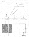
- FIG. 9 a case is assumed in which the leakage oil 8 does not adhere to the specular reflected portion 9 on the target object surface and the leakage oil 8A adheres to the vicinity 15 of the specular reflected portion on the target object surface. This is based on an assumption that there is leakage oil only in the peripheral portion of the specular reflection portion of the target object surface in the captured image. At this time, only specular reflected light is observed by the imaging device 3 from the boundary portion 11A between the leakage oil 8A and the target object.
- the bright portion when a bright portion and a dark portion are observed at the end portion of the image, and the bright portion is observed in the dark portion, the bright portion can be set as the oil leakage portion.
- leakage oil site can be extracted alone in the same manner as in the first embodiment by using the feature of the pattern configured by the three-layer structure and by using the machine learning method.
- the leakage oil detection device of the present embodiment when the background noise due to the daytime sunlight is large, the leakage oil can be detected with high accuracy.
Landscapes
- Physics & Mathematics (AREA)
- General Physics & Mathematics (AREA)
- Engineering & Computer Science (AREA)
- Quality & Reliability (AREA)
- Computer Vision & Pattern Recognition (AREA)
- Theoretical Computer Science (AREA)
- Investigating Or Analysing Materials By Optical Means (AREA)
- Examining Or Testing Airtightness (AREA)
Abstract
Description
- The present invention relates to a leakage oil detection device and a leakage oil detection method, and particularly to a leakage oil detection device and a leakage oil detection method suitable for leakage oil detection of an oil filled apparatus such as a transformer, a condenser, a hydraulic operation device of a gas insulated switchgear (GIS), a rectifier, a converter, and an inverter.
- In related arts, in an oil storage tank or an oil filled apparatus such as a transformer, there has been a concern that oil leakage may occur due to deterioration, an accident, or the like. Since leakage oil may lead to environmental pollution or a disaster, there has been a demand for a technique for detecting leakage oil in an initial stage simply and with high accuracy.
- As a technique in a related art for solving the problem, there is a technique described in
PTL 1.PTL 1 describes a technique of detecting leakage oil by detecting fluorescence reflected by the leakage oil when ultraviolet light including an absorption wavelength of the leakage oil is irradiated to an object to be measured (an inspect target object such as a transformer), and more specifically, calculating the brightness and saturation of each pixel of a captured image by performing image processing on the pixels during ultraviolet light irradiation, creating a brightness-saturation graph and a brightness-saturation characteristic curve, and recognizing pixels deviated from the brightness-saturation characteristic curve by a predetermined value or more as a fluorescent spot, that is, a leakage oil spot. - PTL 1:
JP-A-2016-90560 - Although the technique described in
PTL 1 is effective for detecting leakage oil in a period of time in which an illuminance is low, such as at night, when background noise due to daytime sunlight is large, a detection accuracy of the leakage oil decreases. - The present invention has been made in view of the above facts, and an object of the present invention is to provide a leakage oil detection device and a leakage oil detection method capable of accurately detecting leakage oil when a background noise due to daytime sunlight is large.
- From the above, the present invention relates to "a leakage oil detection device configured to detect leakage oil in an oil filled apparatus, the leakage oil detection device including: a light source configured to irradiate the oil filled apparatus with light; an imaging device configured to capture an image of the oil filled apparatus; a control device configured to control operations of the light source and the imaging device; a storage device configured to store a captured image; an image processing device configured to process the stored image; and a display device configured to display a processing result, in which the light source and the imaging device are arranged in a manner of being capable of capturing specular reflection light from a surface of the oil filled apparatus as a target object, and the image processing device recognizes a brightest portion and a dark portion adjacent to the brightest portion on the captured image as leakage oil adhesion portions when a three-layer structure of luminance having bright portions having different luminances and a dark portion is observed in the image."
- Further, the present invention relates to "a leakage oil detection device configured to detect leakage oil in an oil filled apparatus, the leakage oil detection device including: a light source configured to irradiate the oil filled apparatus with light; an imaging device configured to capture an image of the oil filled apparatus; a control device configured to control operations of the light source and the imaging device; a storage device configured to store a captured image; an image processing device configured to process the stored image; and a display device configured to display a processing result, in which the light source and the imaging device are arranged in a manner of being capable of capturing specular reflection light from a surface of the oil filled apparatus as a target object, and the image processing device recognizes a bright portion in luminance as a leakage oil adhesion portion when the bright portion is observed inside a dark portion of the captured image at an end portion of the image."
- Further, the present invention relates to "a leakage oil detection method for detecting leakage oil of an oil filled apparatus by using an image obtained by irradiating the oil filled apparatus with light and capturing an image of the oil filled apparatus, the leakage oil detection method including: recognizing a brightest portion and a dark portion adjacent to the brightest portion on the captured image as leakage oil adhesion portions when a three-layer structure of luminance having bright portions having different luminances and a dark portion is observed in the image."
- Further, the present invention relates to "a leakage oil detection method for detecting leakage oil of an oil filled apparatus by using an image obtained by irradiating the oil filled apparatus with light and capturing an image of the oil filled apparatus, the leakage oil detection method including: recognizing a bright portion in luminance as a leakage oil adhesion portion when the bright portion is observed inside a dark portion of the captured image at an end portion of the image."
- According to the present invention, leakage oil can be accurately detected when a background noise due to daytime sunlight is large.
-
- [
FIG. 1] FIG. 1 is a diagram showing a schematic configuration example of a leakageoil detection device 100 according to a first embodiment. - [
FIG. 2] FIG. 2 is a diagram for explaining a concept of a leakage oil detection method according to the present invention. - [
FIG. 3] FIG. 3 is a diagram showing the concept of extracting a leakage oil site using a machine learning method. - [
FIG. 4] FIG. 4 is a diagram showing the schematic configuration example of the leakageoil detection device 100 according to the first embodiment. - [
FIG. 5] FIG. 5 is a spectrum pouch diagram of oil when irradiated with ultraviolet light according to a second embodiment. - [
FIG. 6] FIG. 6 is a diagram for explaining reflected light from a target object surface in the second embodiment. - [
FIG. 7] FIG. 7 is a schematic view explaining reduction in light source intensity when afilter 14 according to the second embodiment is used. - [
FIG. 8] FIG. 8 is a diagram for explaining a concept of a leakage oil detection method according to a third embodiment of the present invention. - [
FIG. 9] FIG. 9 is a diagram for explaining a concept of a leakage oil detection method according to a fourth embodiment of the present invention. - Hereinafter, embodiments of a leakage oil detection device and a leakage oil detection method of the present invention will be described with reference to the drawings. In the embodiments, the same components are denoted by the same reference numerals.
- A leakage
oil detection device 100 and a leakage oil detection method according to the first embodiment of the present invention for inspecting oil adhering to a surface of an oil filled apparatus will be described with reference toFIGS. 1 to 3 . In the present embodiment, an oil filled transformer in a substation will be described as an example. -
FIG. 1 is a diagram showing a schematic configuration example of aninspection target object 1 and a leakageoil detection device 100 according to a first embodiment. Theinspection target object 1 is an oil filled apparatus such as a transformer, a capacitor, a hydraulic operation device of a gas insulated switchgear (GIS), a rectifier, an inverter, or a converter. - In the present embodiment, an oil filled transformer disposed in the substation will be described as the
inspection target object 1. - As shown in
FIG. 1 , the leakageoil detection device 100 includes alight source 2, animaging device 3, acontrol device 4 that controls the operations of thedevices storage device 5 that stores captured images, animage processing device 6 that processes the stored images, and adisplay device 7 that displays processing results. The leakageoil detection device 100 captures an image of aleakage oil 8 adhering to a surface of theinspection target object 1, and finally displays an inspection result of the leakage oil on thedisplay device 7. - Here, any lamp including visible light may be used as the
light source 2. As theimaging device 3, a general-purpose product such as a digital camera or a monitoring camera that captures visible light can be used. - In the present invention, the
light source 2, which is a visible light source, is used, and the specular reflected light of the oil is captured by theimaging device 3, and thereby minute leakage oil is detected. -
FIG. 2 is a diagram for explaining a concept of a leakage oil detection method according to the present invention. Only a specular reflection portion of the target object surface is shown. An upper part ofFIG. 2 shows the surface of thetarget object 1 to which theleakage oil 8 is attached, and a lower part ofFIG. 2 shows luminances of parts in the captured image of the surface of thetarget object 1. - Although as shown in the upper part of
FIG. 2 , when theleakage oil 8 adheres to the surface of thetarget object 1, theoutermost surface 8a of the oil is parallel to the surface of thetarget object 1, aboundary portion 8b between the oil and the target object surface is formed. Here, it is assumed that thelight source 2 and theimaging device 3 are arranged in a manner of being capable to capture specular reflected light from the surface of thetarget object 1. In an example ofFIG. 1 , thelight source 2 and theimaging device 3 are installed at positions in a direction orthogonal to the surface of thetarget object 1, and the reflected light from the surface of thetarget object 1 is imaged by theimaging device 3. Accordingly, when theoil 8 adheres to the portion of the specular reflected light, the specular reflected light from theoil 8 is also captured in the same manner. - However, at a
boundary portion 8b between theoil 8 and thetarget object 1, reflected light is directed in another direction different from a direction toward theimaging device 3, and therefore the specular reflected light is not observed by theimaging device 3. Therefore, on the captured image, an oil surface specular reflectedlight portion 10 corresponding to theoutermost surface 8a of theoil 8 and a target object surface specular reflectedlight portion 9 corresponding to the surface to which the oil is not attached are bright, but an oil surface specular reflectedlight portion 11 corresponding to theboundary portion 8b between the oil and the target object is dark. - When comparing the oil surface specular reflected
light portion 10 and the target object surface specular reflectedlight portion 9, the oil surface specular reflectedlight portion 10 is observed as an image brighter than the target object surface specular reflectedlight portion 9 because a reflectance of theoil 8 with respect to visible light is higher than a reflectance of the surface of thetarget object 1. - That is, as shown in the lower part of
FIG. 2 , in the image, K1 > K3 > K2, where the luminance of the oil surface specularly reflectedlight portion 10 is K1, the luminance of theboundary portion 11 between the oil and the target object is K2, and the luminance of the target object surface specular reflectedlight generating portion 9 is K3. - As a result, a three-layer structure as shown in the lower part of
FIG. 2 is observed in the observed image. The oil surface specular reflectedportion 10 is the brightest, theadjacent boundary portion 11 between the oil and the target object is dark, and the subsequently adjacent specular reflectedportion 9 of the target object surface is bright. In addition, the luminance of the oil surfacespecular reflection portion 10 is observed to be lower than the luminance of the specular reflected portion of the target object surface. - In this way, when an adjacent three-layer structure is observed as a portion having the luminances of K1 > K3 > K2, both the oil surface specular reflected
portion 10 and theadjacent boundary portion 11 between theoil 8 and thetarget object 1 are recognized as leakage oil sites. - Further, the leakage oil site can be extracted alone by using the feature of the pattern configured by the three-layer structure and by using a machine learning method.
-
FIG. 3 is a diagram showing a concept of extracting a leakage oil site using the machine learning method. As shown inFIG. 3 , as a machine learning method, first, shapes ofvarious target objects 1, an irradiation shape of a light source, and a state of leakage oil are considered, a large amount of images are captured to obtainimages 1a to 1n as learning data, and a leakage oil pattern is self-learned in theimage processing device 6. Next, adetermination image 1x is input, and theleakage oil 8 is extracted alone from thedetermination image 1x based on the learning result. - When the portion of the extracted
leakage oil 8 is provided on an original image or the same image obtained when the light source is not irradiated by a method such as marker attachment and displayed on thedisplay device 7, even an unskilled inspector can easily identify a leakage oil location. - It is not necessary to perform all procedures of the present embodiment, and a part of the procedures can be performed alone according to a situation of the location where the procedures are performed.
- According to the leakage oil detection device of the present embodiment, when background noise due to daytime sunlight is large, leakage oil can be detected with high accuracy.
- A leakage
oil detection device 100 and the leakage oil detection method according to the second embodiment of the present invention for inspecting oil adhering to the surface of the oil filled apparatus will be described with reference toFIGS. 4 to 6 . Repetitive descriptions of points common to the first embodiment will be omitted. - In the leakage
oil detection device 100 according to the second embodiment shown inFIG. 4 , light from alight source 12 includes both ultraviolet light and visible light. Afilter 13 is mounted in front of thelight source 12. Thefilter 13 transmits ultraviolet light having a center wavelength of 365 nm and a half value width of about 10 nm, and visible light having a center wavelength of 405 nm and a half value width of about 10 nm. Of course, two filters may be used. Similarly, afilter 14 is mounted in front of theimaging device 3. Thefilter 14 transmits the visible light having the center wavelength of 405 nm and the half value width of about 10 nm. -
FIG. 5 shows a porch diagram of a spectrum obtained when a mineral oil for a transformer is irradiated with an ultraviolet light source having a peak value of 365 nm. A strongest peak was observed in the vicinity of 405nm. -
FIG. 6 is a diagram for explaining reflected light from the target object surface according to the second embodiment. As shown inFIG. 6 , when theoil 8 is irradiated with ultraviolet light having a peak value of 365 nm, fluorescence from the oil is also observed in addition to the reflected light. At the time, intensity K1' of light from oil surface specular reflectedportion 10 = intensity of specular reflected light K1 + fluorescence, intensity K2' of light fromadjacent boundary portion 11 between oil and object = intensity of diffuse reflection light + fluorescence, and intensity K3' of light from subsequently adjacent specular reflectedportion 9 of target object surface = intensity of specular reflection light. In this way, fluorescence is not observed in a portion to which oil is not attached. In this way, the intensity of the light at the oil surface specularreflection generating portion 10 can be further improved, and therefore a detection sensitivity can be improved. - In general, since the intensity of the fluorescence is weaker than that of the specular reflection light, the brightness of the
boundary portion 11 between theoil 8 and thetarget object 1 is the lowest as compared with the luminance of the oil surface specular reflectedportion 10 and the specular reflectedportion 9 on the target object surface. - On the other hand, when the
filter 14 having a center wavelength of 405 nm and a half-value width of about 10 nm is used, an intensity of ambient light can be reduced by about 90%. For example, as shown inFIG. 7 , when thefilter 14 is not used, an intensity P1 of the light source needs to be larger than the intensity of ambient light BG1; on the other hand, when thefilter 14 is used, an intensity P2 of the light source is only required to be larger than the intensity of ambient light intensity BG2. Therefore, the required intensity of the light source can also be greatly reduced. - Of course, when a wavelength of an irradiation light source and a color of a fluorescence are different depending on a type of the oil, the present method can be applied by selecting a filter having an appropriate wavelength range.
- It is not necessary to perform all procedures of the present embodiment, and a part of the procedures can be performed alone according to a situation of the location where the procedures are performed.
- According to the leakage oil detection device of the present embodiment, the required intensity of the light source can be reduced, and a cost of the detection device can be reduced.
- The leakage oil detection method according to the third embodiment of the present invention for inspecting oil adhering to the surface of an oil filled apparatus will be described with reference to
FIG. 8 . Repetitive descriptions of common points as in the first embodiment are omitted. - In the third embodiment, as shown in
FIG. 8 , a case is assumed in which theleakage oil 8 adheres to the specular reflectedportion 9 on the target object surface and theleakage oil 8A adheres to avicinity 15 of the specular reflected portion on the target object surface. At this time, in addition to the oil surface specular reflectedportion 10, specular reflected light is observed by theimaging device 3 from aboundary portion 11A between theleakage oil 8A and the target object. The above is based on an assumption that leakage oil is present in each of a central portion and a peripheral portion of the captured image. - In such a case, a five-layer structure as shown in a lower part of
FIG. 8 is observed. As a result, thevicinity 15 of the specular reflected portion on the target object surface is dark, theboundary portion 11A between theleakage oil 8A and the target object and the oil surface specularreflection generating portion 10 are the brightest, theadjacent boundary portion 11 between the oil and the target object is dark, and the subsequently adjacent specular reflectedportion 9 of the target object surface is bright. In addition, the luminance of theboundary portion 11A between theleakage oil 8A and the target object and the oil surface specularreflection generating portion 10 is higher than the luminance of the specular reflectedportion 9 on the target object surface. - In this case, the
portion 11A observed brightly in the vicinity of the specular reflected portion on the target object surface, and the oil surface specularreflection generating portion 10 and the adjacentdark portion 11 in the specular reflected portion of the target object surface are recognized as leakage oil adhesion portions. - In this case, in addition to the three-layer structure in a central portion of the image in
FIG. 2 , a bright portion and a dark portion are observed in an end portion of the image, and in this case, the bright portion can be regarded as an oil leakage portion. That is, when a bright portion and a dark portion are observed at the end portion of the image, and particularly when THE bright portion is observed in the dark portion, the bright portion can be regarded as the oil leakage portion. - In some cases, the luminance of the
boundary portion 11 between the oil and the target object and the luminance of thevicinity 15 of the target object surface specular reflected light generating portion are substantially equal to each other. - Further, the leakage oil site can be extracted alone in the same manner as in the first embodiment by using the feature of the pattern configured by the five-layer structure described above and by using a machine learning method.
- As described above, according to the leakage oil detection device of the present embodiment, when the background noise due to the daytime sunlight is large, the leakage oil can be detected with high accuracy.
- Next, the leakage oil detection method according to the fourth embodiment of the present invention for inspecting oil adhering to the surface of an oil filled apparatus will be described with reference to
FIG. 9 . Repetitive descriptions of common points as in the first embodiment and the third embodiment are omitted. - In
FIG. 9 , a case is assumed in which theleakage oil 8 does not adhere to the specular reflectedportion 9 on the target object surface and theleakage oil 8A adheres to thevicinity 15 of the specular reflected portion on the target object surface. This is based on an assumption that there is leakage oil only in the peripheral portion of the specular reflection portion of the target object surface in the captured image. At this time, only specular reflected light is observed by theimaging device 3 from theboundary portion 11A between theleakage oil 8A and the target object. - In this way, a three-layer structure as shown in the lower part of
FIG. 9 is observed. At the time, thevicinity 15 of the target object surface specular reflected light generating portion is dark, theadjacent boundary portion 11A between theleakage oil 8A and the target object is the brightest, and the adjacent specularreflection generating portion 9 of the target object surface is bright, but has a luminance lower than that of theboundary portion 11A. - Also in this case, similar as in the third embodiment, when a bright portion and a dark portion are observed at the end portion of the image, and the bright portion is observed in the dark portion, the bright portion can be set as the oil leakage portion.
- Further, the leakage oil site can be extracted alone in the same manner as in the first embodiment by using the feature of the pattern configured by the three-layer structure and by using the machine learning method.
- As described above, according to the leakage oil detection device of the present embodiment, when the background noise due to the daytime sunlight is large, the leakage oil can be detected with high accuracy.
- Various combinations of the first to fourth embodiments are possible. A detection result is not affected. There are various changes in the pattern depending on the situation, and a basic principle is the same.
-
- 100: leakage oil detection device
- 1, 1a, 1b, 1n, 1x: inspection target object
- 2: light source
- 3: imaging device
- 4: control device
- 5: storage device
- 6: image processing device
- 7: display device
- 8: leakage oil
- 9: specular reflected portion on target object surface
- 10, 10a: oil surface specular reflected portion
- 11, 11a: boundary portion between oil and target object
- 12: light source
- 13: filter
- 14: filter
- 15: vicinity of specular reflected portion on target object surface
Claims (6)
- A leakage oil detection device configured to detect leakage oil in an oil filled apparatus, the leakage oil detection device comprising:a light source configured to irradiate the oil filled apparatus with light;an imaging device configured to capture an image of the oil filled apparatus;a control device configured to control operations of the light source and the imaging device;a storage device configured to store a captured image;an image processing device configured to process the stored image; anda display device configured to display a processing result, whereinthe light source and the imaging device are arranged in a manner of being capable of capturing specular reflection light from a surface of the oil filled apparatus as a target object, andthe image processing device recognizes a brightest portion and a dark portion adjacent to the brightest portion on the captured image as leakage oil adhesion portions when a three-layer structure of luminance having bright portions having different luminances and a dark portion is observed in the image.
- The leakage oil detection device according to claim 1, whereinthe image processing device extracts only a leakage oil site by machine learning method with respect to the observed three-layer structure of luminance, andthe display device displays by adding a marker to an original image or the same image obtained without irradiation of the light source.
- The leakage oil detection device according to claim 1, whereinlight of the light source includes both ultraviolet light and visible light,a filter that transmits the ultraviolet light and the visible light is mounted in front of the light source, anda filter that transmits visible light is mounted in front of the imaging device.
- A leakage oil detection device configured to detect leakage oil in an oil filled apparatus, the leakage oil detection device comprising:a light source configured to irradiate the oil filled apparatus with light;an imaging device configured to capture an image of the oil filled apparatus;a control device configured to control operations of the light source and the imaging device;a storage device configured to store a captured image;an image processing device configured to process the stored image; anda display device configured to display a processing result, whereinthe light source and the imaging device are arranged in a manner of being capable of capturing specular reflection light from a surface of the oil filled apparatus as a target object, andthe image processing device recognizes a bright portion in luminance as a leakage oil adhesion portion when the bright portion is observed inside a dark portion of the captured image at an end portion of the image.
- A leakage oil detection method for detecting leakage oil of an oil filled apparatus by using an image obtained by irradiating the oil filled apparatus with light and capturing an image of the oil filled apparatus, the leakage oil detection method comprising:
recognizing a brightest portion and a dark portion adjacent to the brightest portion on the captured image as leakage oil adhesion portions when a three-layer structure of luminance having bright portions having different luminances and a dark portion is observed in the image. - A leakage oil detection method for detecting leakage oil of an oil filled apparatus by using an image obtained by irradiating the oil filled apparatus with light and capturing an image of the oil filled apparatus, the leakage oil detection method comprising:
recognizing a bright portion in luminance as a leakage oil adhesion portion when the bright portion is observed inside a dark portion of the captured image at an end portion of the image.
Applications Claiming Priority (2)
| Application Number | Priority Date | Filing Date | Title |
|---|---|---|---|
| JP2019024380A JP7096780B2 (en) | 2019-02-14 | 2019-02-14 | Oil spill detection device and oil spill detection method |
| PCT/JP2019/043729 WO2020166148A1 (en) | 2019-02-14 | 2019-11-07 | Leakage oil detection apparatus and leakage oil detection method |
Publications (3)
| Publication Number | Publication Date |
|---|---|
| EP3926319A1 true EP3926319A1 (en) | 2021-12-22 |
| EP3926319A4 EP3926319A4 (en) | 2022-11-09 |
| EP3926319B1 EP3926319B1 (en) | 2025-01-15 |
Family
ID=72044205
Family Applications (1)
| Application Number | Title | Priority Date | Filing Date |
|---|---|---|---|
| EP19915211.7A Active EP3926319B1 (en) | 2019-02-14 | 2019-11-07 | Leakage oil detection apparatus and leakage oil detection method |
Country Status (4)
| Country | Link |
|---|---|
| US (1) | US11994448B2 (en) |
| EP (1) | EP3926319B1 (en) |
| JP (1) | JP7096780B2 (en) |
| WO (1) | WO2020166148A1 (en) |
Families Citing this family (2)
| Publication number | Priority date | Publication date | Assignee | Title |
|---|---|---|---|---|
| CN114674503B (en) * | 2022-05-30 | 2022-08-23 | 中海石油(中国)有限公司 | Underwater caisson oil leak detection device |
| JP2024114397A (en) * | 2023-02-13 | 2024-08-23 | トヨタ自動車株式会社 | Image Processing Device |
Family Cites Families (13)
| Publication number | Priority date | Publication date | Assignee | Title |
|---|---|---|---|---|
| JPS6232336A (en) * | 1985-08-05 | 1987-02-12 | Toshiba Corp | Liquid leak detecting method by itv camera |
| JPS636432A (en) * | 1986-06-26 | 1988-01-12 | Toshiba Corp | Method and device for leak detection |
| JPH08128916A (en) * | 1994-10-31 | 1996-05-21 | Mitsubishi Electric Corp | Oil leak detector |
| JPH09304281A (en) * | 1996-05-09 | 1997-11-28 | Tokyo Electric Power Co Inc:The | Oil detector |
| US7565830B2 (en) * | 2005-10-18 | 2009-07-28 | E.F. Products | System, methods, and compositions for detecting and inhibiting leaks in engine oil systems |
| JP5351081B2 (en) | 2010-03-09 | 2013-11-27 | 株式会社四国総合研究所 | Oil leakage remote monitoring device and method |
| JP2013101028A (en) | 2011-11-08 | 2013-05-23 | Tohoku Electric Power Co Inc | Oil leakage detector |
| JP6411856B2 (en) * | 2014-10-17 | 2018-10-24 | 株式会社日立製作所 | Oil leak detection device and method |
| JP6509597B2 (en) | 2014-10-29 | 2019-05-08 | 株式会社日立製作所 | Oil leakage detection device, oil leakage detection method and image processing unit |
| US9898830B2 (en) * | 2015-03-17 | 2018-02-20 | Hitachi, Ltd. | Oil leakage detector and oil leakage detection method |
| JP6498552B2 (en) * | 2015-07-15 | 2019-04-10 | 株式会社日立製作所 | Oil leak detection system |
| JP6628597B2 (en) | 2015-12-21 | 2020-01-08 | 三菱電機株式会社 | Power generation system |
| JP6989444B2 (en) * | 2018-01-18 | 2022-01-05 | 株式会社日立製作所 | Work terminal, oil leak detection device, and oil leak detection method |
-
2019
- 2019-02-14 JP JP2019024380A patent/JP7096780B2/en active Active
- 2019-11-07 US US17/428,123 patent/US11994448B2/en active Active
- 2019-11-07 WO PCT/JP2019/043729 patent/WO2020166148A1/en not_active Ceased
- 2019-11-07 EP EP19915211.7A patent/EP3926319B1/en active Active
Also Published As
| Publication number | Publication date |
|---|---|
| JP2020134188A (en) | 2020-08-31 |
| US20220057291A1 (en) | 2022-02-24 |
| WO2020166148A1 (en) | 2020-08-20 |
| EP3926319A4 (en) | 2022-11-09 |
| US11994448B2 (en) | 2024-05-28 |
| JP7096780B2 (en) | 2022-07-06 |
| EP3926319B1 (en) | 2025-01-15 |
Similar Documents
| Publication | Publication Date | Title |
|---|---|---|
| US20250336050A1 (en) | Method for processing image, computer-readable storage medium, and electronic device | |
| TWI550264B (en) | Oil leakage detection device and method | |
| JP2008170325A (en) | Spot defect detection method and spot defect detection apparatus | |
| JP6052590B2 (en) | Surface inspection apparatus and surface inspection method for automobile body | |
| JP2007086056A (en) | Defect detection method and defect detection apparatus | |
| JP2011132010A (en) | Wire rope inspecting device | |
| JP2008170256A (en) | Defect detection method, defect detection program, and inspection apparatus | |
| CN104933978A (en) | Detection method and detection apparatus for display panel | |
| US20130100089A1 (en) | Newton ring mura detection system | |
| US11994448B2 (en) | Leakage oil detection device and leakage oil detection method | |
| CN108663371B (en) | Method and system for detecting dust and foreign matters on display panel | |
| CN103792705A (en) | Detecting method and detecting device for detecting substrate defects | |
| CN105277574B (en) | Multi-exposure image mixing detection method applying repeated exposure | |
| CN111443509A (en) | Method for detecting L CD liquid crystal screen black and white spots and flicker defects | |
| CN107144993B (en) | Display panel detection method and device | |
| JP2007010620A (en) | Screw part inspection device and screw part test method | |
| CN105510429B (en) | Fluorescent magnetic particle flaw detection detection method based on image procossing and detecting system | |
| CN101443649A (en) | Surface inspection device | |
| KR20140082333A (en) | Method and apparatus of inspecting mura of flat display | |
| JP2005345290A (en) | Streak defect detection method and apparatus | |
| CN109035235A (en) | A kind of car light light guide acetes chinensis method | |
| KR20140121068A (en) | Method and apparatus of inspecting mura of flat display | |
| CN111735823B (en) | Defect detection method and system for module | |
| JPH0460540B2 (en) | ||
| KR20190139604A (en) | Apparatus and method for surface inspection |
Legal Events
| Date | Code | Title | Description |
|---|---|---|---|
| STAA | Information on the status of an ep patent application or granted ep patent |
Free format text: STATUS: THE INTERNATIONAL PUBLICATION HAS BEEN MADE |
|
| PUAI | Public reference made under article 153(3) epc to a published international application that has entered the european phase |
Free format text: ORIGINAL CODE: 0009012 |
|
| STAA | Information on the status of an ep patent application or granted ep patent |
Free format text: STATUS: REQUEST FOR EXAMINATION WAS MADE |
|
| 17P | Request for examination filed |
Effective date: 20210914 |
|
| AK | Designated contracting states |
Kind code of ref document: A1 Designated state(s): AL AT BE BG CH CY CZ DE DK EE ES FI FR GB GR HR HU IE IS IT LI LT LU LV MC MK MT NL NO PL PT RO RS SE SI SK SM TR |
|
| DAV | Request for validation of the european patent (deleted) | ||
| DAX | Request for extension of the european patent (deleted) | ||
| A4 | Supplementary search report drawn up and despatched |
Effective date: 20221010 |
|
| RIC1 | Information provided on ipc code assigned before grant |
Ipc: G01M 3/38 20060101AFI20221004BHEP |
|
| GRAP | Despatch of communication of intention to grant a patent |
Free format text: ORIGINAL CODE: EPIDOSNIGR1 |
|
| STAA | Information on the status of an ep patent application or granted ep patent |
Free format text: STATUS: GRANT OF PATENT IS INTENDED |
|
| INTG | Intention to grant announced |
Effective date: 20240827 |
|
| RAP1 | Party data changed (applicant data changed or rights of an application transferred) |
Owner name: HITACHI ENERGY LTD |
|
| GRAS | Grant fee paid |
Free format text: ORIGINAL CODE: EPIDOSNIGR3 |
|
| GRAA | (expected) grant |
Free format text: ORIGINAL CODE: 0009210 |
|
| STAA | Information on the status of an ep patent application or granted ep patent |
Free format text: STATUS: THE PATENT HAS BEEN GRANTED |
|
| AK | Designated contracting states |
Kind code of ref document: B1 Designated state(s): AL AT BE BG CH CY CZ DE DK EE ES FI FR GB GR HR HU IE IS IT LI LT LU LV MC MK MT NL NO PL PT RO RS SE SI SK SM TR |
|
| REG | Reference to a national code |
Ref country code: CH Ref legal event code: EP Ref country code: GB Ref legal event code: FG4D |
|
| REG | Reference to a national code |
Ref country code: DE Ref legal event code: R096 Ref document number: 602019064989 Country of ref document: DE |
|
| REG | Reference to a national code |
Ref country code: IE Ref legal event code: FG4D |
|
| P01 | Opt-out of the competence of the unified patent court (upc) registered |
Free format text: CASE NUMBER: APP_7537/2025 Effective date: 20250213 |
|
| REG | Reference to a national code |
Ref country code: NL Ref legal event code: MP Effective date: 20250115 |
|
| PG25 | Lapsed in a contracting state [announced via postgrant information from national office to epo] |
Ref country code: NL Free format text: LAPSE BECAUSE OF FAILURE TO SUBMIT A TRANSLATION OF THE DESCRIPTION OR TO PAY THE FEE WITHIN THE PRESCRIBED TIME-LIMIT Effective date: 20250115 |
|
| PG25 | Lapsed in a contracting state [announced via postgrant information from national office to epo] |
Ref country code: RS Free format text: LAPSE BECAUSE OF FAILURE TO SUBMIT A TRANSLATION OF THE DESCRIPTION OR TO PAY THE FEE WITHIN THE PRESCRIBED TIME-LIMIT Effective date: 20250415 |
|
| PG25 | Lapsed in a contracting state [announced via postgrant information from national office to epo] |
Ref country code: FI Free format text: LAPSE BECAUSE OF FAILURE TO SUBMIT A TRANSLATION OF THE DESCRIPTION OR TO PAY THE FEE WITHIN THE PRESCRIBED TIME-LIMIT Effective date: 20250115 |
|
| PG25 | Lapsed in a contracting state [announced via postgrant information from national office to epo] |
Ref country code: PL Free format text: LAPSE BECAUSE OF FAILURE TO SUBMIT A TRANSLATION OF THE DESCRIPTION OR TO PAY THE FEE WITHIN THE PRESCRIBED TIME-LIMIT Effective date: 20250115 |
|
| PG25 | Lapsed in a contracting state [announced via postgrant information from national office to epo] |
Ref country code: ES Free format text: LAPSE BECAUSE OF FAILURE TO SUBMIT A TRANSLATION OF THE DESCRIPTION OR TO PAY THE FEE WITHIN THE PRESCRIBED TIME-LIMIT Effective date: 20250115 |
|
| REG | Reference to a national code |
Ref country code: LT Ref legal event code: MG9D |
|
| PG25 | Lapsed in a contracting state [announced via postgrant information from national office to epo] |
Ref country code: NO Free format text: LAPSE BECAUSE OF FAILURE TO SUBMIT A TRANSLATION OF THE DESCRIPTION OR TO PAY THE FEE WITHIN THE PRESCRIBED TIME-LIMIT Effective date: 20250415 Ref country code: IS Free format text: LAPSE BECAUSE OF FAILURE TO SUBMIT A TRANSLATION OF THE DESCRIPTION OR TO PAY THE FEE WITHIN THE PRESCRIBED TIME-LIMIT Effective date: 20250515 |
|
| REG | Reference to a national code |
Ref country code: AT Ref legal event code: MK05 Ref document number: 1760116 Country of ref document: AT Kind code of ref document: T Effective date: 20250115 |
|
| PG25 | Lapsed in a contracting state [announced via postgrant information from national office to epo] |
Ref country code: HR Free format text: LAPSE BECAUSE OF FAILURE TO SUBMIT A TRANSLATION OF THE DESCRIPTION OR TO PAY THE FEE WITHIN THE PRESCRIBED TIME-LIMIT Effective date: 20250115 |
|
| PG25 | Lapsed in a contracting state [announced via postgrant information from national office to epo] |
Ref country code: LV Free format text: LAPSE BECAUSE OF FAILURE TO SUBMIT A TRANSLATION OF THE DESCRIPTION OR TO PAY THE FEE WITHIN THE PRESCRIBED TIME-LIMIT Effective date: 20250115 Ref country code: PT Free format text: LAPSE BECAUSE OF FAILURE TO SUBMIT A TRANSLATION OF THE DESCRIPTION OR TO PAY THE FEE WITHIN THE PRESCRIBED TIME-LIMIT Effective date: 20250515 |
|
| PG25 | Lapsed in a contracting state [announced via postgrant information from national office to epo] |
Ref country code: BG Free format text: LAPSE BECAUSE OF FAILURE TO SUBMIT A TRANSLATION OF THE DESCRIPTION OR TO PAY THE FEE WITHIN THE PRESCRIBED TIME-LIMIT Effective date: 20250115 Ref country code: GR Free format text: LAPSE BECAUSE OF FAILURE TO SUBMIT A TRANSLATION OF THE DESCRIPTION OR TO PAY THE FEE WITHIN THE PRESCRIBED TIME-LIMIT Effective date: 20250416 |
|
| PG25 | Lapsed in a contracting state [announced via postgrant information from national office to epo] |
Ref country code: AT Free format text: LAPSE BECAUSE OF FAILURE TO SUBMIT A TRANSLATION OF THE DESCRIPTION OR TO PAY THE FEE WITHIN THE PRESCRIBED TIME-LIMIT Effective date: 20250115 |
|
| PG25 | Lapsed in a contracting state [announced via postgrant information from national office to epo] |
Ref country code: SE Free format text: LAPSE BECAUSE OF FAILURE TO SUBMIT A TRANSLATION OF THE DESCRIPTION OR TO PAY THE FEE WITHIN THE PRESCRIBED TIME-LIMIT Effective date: 20250115 |
|
| PG25 | Lapsed in a contracting state [announced via postgrant information from national office to epo] |
Ref country code: SM Free format text: LAPSE BECAUSE OF FAILURE TO SUBMIT A TRANSLATION OF THE DESCRIPTION OR TO PAY THE FEE WITHIN THE PRESCRIBED TIME-LIMIT Effective date: 20250115 |
|
| PG25 | Lapsed in a contracting state [announced via postgrant information from national office to epo] |
Ref country code: DK Free format text: LAPSE BECAUSE OF FAILURE TO SUBMIT A TRANSLATION OF THE DESCRIPTION OR TO PAY THE FEE WITHIN THE PRESCRIBED TIME-LIMIT Effective date: 20250115 |
|
| PG25 | Lapsed in a contracting state [announced via postgrant information from national office to epo] |
Ref country code: IT Free format text: LAPSE BECAUSE OF FAILURE TO SUBMIT A TRANSLATION OF THE DESCRIPTION OR TO PAY THE FEE WITHIN THE PRESCRIBED TIME-LIMIT Effective date: 20250115 |
|
| REG | Reference to a national code |
Ref country code: DE Ref legal event code: R097 Ref document number: 602019064989 Country of ref document: DE |
|
| PG25 | Lapsed in a contracting state [announced via postgrant information from national office to epo] |
Ref country code: CZ Free format text: LAPSE BECAUSE OF FAILURE TO SUBMIT A TRANSLATION OF THE DESCRIPTION OR TO PAY THE FEE WITHIN THE PRESCRIBED TIME-LIMIT Effective date: 20250115 Ref country code: EE Free format text: LAPSE BECAUSE OF FAILURE TO SUBMIT A TRANSLATION OF THE DESCRIPTION OR TO PAY THE FEE WITHIN THE PRESCRIBED TIME-LIMIT Effective date: 20250115 |
|
| PG25 | Lapsed in a contracting state [announced via postgrant information from national office to epo] |
Ref country code: RO Free format text: LAPSE BECAUSE OF FAILURE TO SUBMIT A TRANSLATION OF THE DESCRIPTION OR TO PAY THE FEE WITHIN THE PRESCRIBED TIME-LIMIT Effective date: 20250115 |
|
| PG25 | Lapsed in a contracting state [announced via postgrant information from national office to epo] |
Ref country code: SK Free format text: LAPSE BECAUSE OF FAILURE TO SUBMIT A TRANSLATION OF THE DESCRIPTION OR TO PAY THE FEE WITHIN THE PRESCRIBED TIME-LIMIT Effective date: 20250115 |
|
| PLBE | No opposition filed within time limit |
Free format text: ORIGINAL CODE: 0009261 |
|
| STAA | Information on the status of an ep patent application or granted ep patent |
Free format text: STATUS: NO OPPOSITION FILED WITHIN TIME LIMIT |
|
| 26N | No opposition filed |
Effective date: 20251016 |
|
| PGFP | Annual fee paid to national office [announced via postgrant information from national office to epo] |
Ref country code: DE Payment date: 20251119 Year of fee payment: 7 |
|
| PGFP | Annual fee paid to national office [announced via postgrant information from national office to epo] |
Ref country code: GB Payment date: 20251121 Year of fee payment: 7 |
|
| PGFP | Annual fee paid to national office [announced via postgrant information from national office to epo] |
Ref country code: FR Payment date: 20251126 Year of fee payment: 7 |