EP3926291A1 - Threat-coping system - Google Patents
Threat-coping system Download PDFInfo
- Publication number
- EP3926291A1 EP3926291A1 EP20841248.6A EP20841248A EP3926291A1 EP 3926291 A1 EP3926291 A1 EP 3926291A1 EP 20841248 A EP20841248 A EP 20841248A EP 3926291 A1 EP3926291 A1 EP 3926291A1
- Authority
- EP
- European Patent Office
- Prior art keywords
- coping
- threat
- target
- area
- processor
- Prior art date
- Legal status (The legal status is an assumption and is not a legal conclusion. Google has not performed a legal analysis and makes no representation as to the accuracy of the status listed.)
- Pending
Links
Images





Classifications
-
- F—MECHANICAL ENGINEERING; LIGHTING; HEATING; WEAPONS; BLASTING
- F41—WEAPONS
- F41A—FUNCTIONAL FEATURES OR DETAILS COMMON TO BOTH SMALLARMS AND ORDNANCE, e.g. CANNONS; MOUNTINGS FOR SMALLARMS OR ORDNANCE
- F41A17/00—Safety arrangements, e.g. safeties
- F41A17/08—Safety arrangements, e.g. safeties for inhibiting firing in a specified direction, e.g. at a friendly person or at a protected area
-
- G—PHYSICS
- G01—MEASURING; TESTING
- G01S—RADIO DIRECTION-FINDING; RADIO NAVIGATION; DETERMINING DISTANCE OR VELOCITY BY USE OF RADIO WAVES; LOCATING OR PRESENCE-DETECTING BY USE OF THE REFLECTION OR RERADIATION OF RADIO WAVES; ANALOGOUS ARRANGEMENTS USING OTHER WAVES
- G01S17/00—Systems using the reflection or reradiation of electromagnetic waves other than radio waves, e.g. lidar systems
- G01S17/66—Tracking systems using electromagnetic waves other than radio waves
-
- F—MECHANICAL ENGINEERING; LIGHTING; HEATING; WEAPONS; BLASTING
- F41—WEAPONS
- F41H—ARMOUR; ARMOURED TURRETS; ARMOURED OR ARMED VEHICLES; MEANS OF ATTACK OR DEFENCE, e.g. CAMOUFLAGE, IN GENERAL
- F41H11/00—Defence installations; Defence devices
- F41H11/02—Anti-aircraft or anti-guided missile or anti-torpedo defence installations or systems
-
- G—PHYSICS
- G01—MEASURING; TESTING
- G01S—RADIO DIRECTION-FINDING; RADIO NAVIGATION; DETERMINING DISTANCE OR VELOCITY BY USE OF RADIO WAVES; LOCATING OR PRESENCE-DETECTING BY USE OF THE REFLECTION OR RERADIATION OF RADIO WAVES; ANALOGOUS ARRANGEMENTS USING OTHER WAVES
- G01S17/00—Systems using the reflection or reradiation of electromagnetic waves other than radio waves, e.g. lidar systems
- G01S17/02—Systems using the reflection of electromagnetic waves other than radio waves
- G01S17/04—Systems determining the presence of a target
-
- G—PHYSICS
- G01—MEASURING; TESTING
- G01S—RADIO DIRECTION-FINDING; RADIO NAVIGATION; DETERMINING DISTANCE OR VELOCITY BY USE OF RADIO WAVES; LOCATING OR PRESENCE-DETECTING BY USE OF THE REFLECTION OR RERADIATION OF RADIO WAVES; ANALOGOUS ARRANGEMENTS USING OTHER WAVES
- G01S17/00—Systems using the reflection or reradiation of electromagnetic waves other than radio waves, e.g. lidar systems
- G01S17/02—Systems using the reflection of electromagnetic waves other than radio waves
- G01S17/06—Systems determining position data of a target
-
- G—PHYSICS
- G06—COMPUTING OR CALCULATING; COUNTING
- G06V—IMAGE OR VIDEO RECOGNITION OR UNDERSTANDING
- G06V20/00—Scenes; Scene-specific elements
- G06V20/35—Categorising the entire scene, e.g. birthday party or wedding scene
- G06V20/38—Outdoor scenes
-
- G—PHYSICS
- G06—COMPUTING OR CALCULATING; COUNTING
- G06V—IMAGE OR VIDEO RECOGNITION OR UNDERSTANDING
- G06V2201/00—Indexing scheme relating to image or video recognition or understanding
- G06V2201/07—Target detection
Definitions
- the present invention relates to a threat coping system.
- Patent Literature 1 discloses a device for controlling headlight of vehicle. This device for controlling generates information on forward vehicle based on image information in which an image of an anterior area is captured and road information concerning a latent trouble when detecting a forward vehicle existing in the anterior area, and controls an irradiation area of the headlight according to the generated forward vehicle information.
- Patent Literature 2 discloses a light irradiation system that confirms safety of a target object, such as a person, to protect from reflection light or scattered light when irradiating laser. This light irradiation system determines a degree of safety of a target object for incident light based on a location of the target object and irradiation direction of the laser light.
- an objective is to provide a threat coping system that suppress misfiring.
- Other objectives would be understood from the following disclosure and description of embodiments.
- a threat coping system is provided with a threat coping device that copes with a coping target and a control device that controls the threat coping device.
- the control device is provided with a no-coping area setting means and a coping instruction means.
- the no-coping area setting means sets a no-coping area based on information of a no-coping target that is not to cope with.
- the coping instruction means generates an instruction signal, that instructs the threat coping device to cope with a coping target, based on the no-coping area.
- a threat coping system 10 copes with coping targets 30 (including a first coping target 30-1 and a second coping target 30-2) that are a threat.
- the threat coping system 10 sets a no-coping area 12 around a no-coping target 20 that is not to cope with such as a passenger plane.
- the threat coping system 10 is configured to suppress influences to the no-coping area 12 when coping with the coping targets 30. For this reason, the threat coping system 10 does not cope with the first coping target 30-1 that exists in the no-coping area 12 and copes with the second coping target 30-2 that is outside the no-coping area 12, for example.
- the coping target 30 includes an Unmanned Aerial Vehicle (UAV), a drone and the like.
- UAV Unmanned Aerial Vehicle
- the threat coping system 10 suppress damages to a no-coping target 20 when coping with coping targets 30.
- the threat coping system 10 copes with the coping targets 30 by use of devices such as a Direct-Energy Weapon (DEW), a machine gun, an anti-aircraft missile, for example.
- DEW Direct-Energy Weapon
- Those devices bring damages to moving bodies that exist around the coping targets 30.
- coping energy may penetrate through a coping target 30 and affect a moving body that exists behind the coping target 30.
- a bullet that missed a coping target 30 may affect a moving body that exists around the coping target 30.
- a DEW includes a laser weapon, a High-Power Microwave (HPM) weapon, an Electromagnetic Pulse (EMP) weapon, and the like.
- HPM High-Power Microwave
- EMP Electromagnetic Pulse
- the threat coping system 10 is provided with a detection device 100, a control device 200 and a threat coping device 300.
- the detection device 100 detects a moving body around it and transmits detection data obtained by detection to the control device 200.
- the control device 200 controls the threat coping device 300 and generates, based on the detection data, a coping signal that instructs to cope with a coping target 30.
- the threat coping device 300 copes with the coping target 30 based on the coping signal.
- the control device 200 is electrically connected to the detection device 100 and the threat coping device 300, wiredly or wirelessly, to transmit and receive various data.
- the detection device 100 detects a moving body included in a preset detection area and generates detection data that indicates information of the detected moving body.
- the detection data include, for example, data that indicates a shape, a location, a speed, a travelling direction and the like of the moving body.
- the detection device 100 includes various sensors such as an optical camera, a Light Detection And Ranging (LIDAR), a radar device, a transponder receiver (for example, a device that receives a signal from an Air Traffic Control (ATC) transponder), an Identification Friend or Foe (IFF), for example.
- LIDAR Light Detection And Ranging
- the optical camera, the LIDAR, the radar device and the transponder receiver detect for example a shape, a location, a speed, a travelling direction or the like of a moving body.
- the IFF detects for example an affiliation or the like of a moving body.
- the control device 200 is provided with a communication device 210, an input output device 220, a storage device 230 and a processor 240.
- the control device 200 decides a coping target 30 to cope with based on the detection data generated by the detection device 100 and instructs the threat coping device 300 to cope with the determined coping target 30.
- the communication device 210 is connected to the detection device 100 and the threat coping device 300, and performs communication with the detection device 100 and the threat coping device 300.
- the communication device 210 transfers data received from the detection device 100 and the threat coping device 300 to the processor 240.
- the communication device 210 transfers signals generated by the processor 240 to the detection device 100 and the threat coping device 300.
- the communication device 210 includes, for example, various interfaces such as a Network Interface Card (NIC) and a Universal Serial Bus (USB).
- NIC Network Interface Card
- USB Universal Serial Bus
- the input output device 220 receives information for the processor 240 to execute a process. In addition, the input output device 220 outputs a result of the process executed by the processor 240.
- the input output device 220 includes a variety of input devices and output devices, and for example, includes a keyboard, a mouse, a microphone, a display, a speaker, a touch panel or the like.
- the storage device 230 stores various data to control the threat coping device 300 such as an assignment program 500 and a coping list 700.
- the storage device 230 is used as a non-transitory tangible storage medium that stores the assignment program 500.
- the assignment program 500 may be provided as a computer program product stored in a computer-readable recording medium 1, or may be provided as a computer program product downloadable from a server.
- the processor 240 performs various data processes to control the threat coping device 300.
- the processor 240 reads out the assignment program 500 from the storage device 230 and executes it to generate a coping signal to cope with the coping target 30.
- the processor 240 includes a Central Processing Unit (CPU) or the like.
- the threat coping device 300 is provided with a communication device 310, an input output device 320, a storage device 330, a processor 340, an aiming sensor 350 and a coping execution device 360.
- the threat coping device 300 copes with the coping target 30 based on the coping signal generated by the control device 200.
- the communication device 310 is connected to the control device 200 and performs communication with the control device 200.
- the communication device 310 transfers data received from the control device 200 to the processor 340.
- the communication device 310 transfers a signal generated by the processor 340 to the control device 200.
- the communication device 310 includes, for example, various interfaces such as a NIC or a USB.
- the communication device 310 may be connected to the detection device 100 and perform communication with the detection device 100.
- the input output device 320 receives information for the processor 340 to execute a process. In addition, the input output device 320 outputs a result of a process executed by the processor 340.
- the input output device 320 includes a variety of input devices and output devices, and for example includes a keyboard, a mouse, a microphone, a display, a speaker, a touch panel or the like.
- the storage device 330 stores various data to cope with the coping target 30, such as a coping program 600.
- the storage device 330 is used as a non-transitory tangible storage medium that stores the coping program 600.
- the coping program 600 may be provided as a computer program product stored in a computer-readable recording medium 1, or may be provided as a computer program product downloadable from a server.
- the assignment program 500 and the coping program 600 may be stored in different recording media 1.
- the processor 340 performs various data processes to cope with the coping target 30.
- the processor 340 reads out the coping program 600 from the storage device 330 and execute it.
- the processor 340 includes a CPU or the like.
- the aiming sensor 350 is used when the threat coping device 300 copes with the coping target 30.
- the aiming sensor 350 detects a location of the coping target 30 when the threat coping device 300 copes with the coping target 30. Data that indicates the detected location is transmitted to the processor 340.
- the coping execution device 360 copes with the coping target 30 based on an instruction from the processor 340. For example, when the coping execution device 360 is a DEW, energy is irradiated to the coping target 30. In addition, when the coping execution device 360 is an anti-aircraft missile system, an anti-aircraft missile is launched to the coping target 30. When the coping execution device 360 is a machine gun, bullets are fired to the coping target 30.
- the assignment program 500 that is executed in the control device 200, is provided with an identification module 510 and a coping instruction module 520.
- the identification module 510 identifies a coping target 30 and a no-coping target 20 from the detected moving bodies, based on the detected data generated by the detection device 100.
- the identification module 510 sets a no-coping area 12 based on the detection data of the identified no-coping target 20.
- the coping instruction module 520 generates a coping signal to cope with the coping target 30, based on the detection data of the coping target 30 and the no-coping area 12.
- the identification module 510 is provided with a moving body identification means 512, a no-coping area setting means 514 and a coping target registration means 516.
- the moving body identification means 512 identifies a no-coping target 20 and a coping target 30 included in the moving bodies identified by the detection device 100, based on the detection data generated by the detection device 100.
- the no-coping area setting means 514 sets a no-coping area 12 for a moving body identified as a no-coping target 20.
- the coping target registration means 516 registers information of a moving body, that is identified as a coping target 30, as a coping target 30 in the coping list 700.
- the coping instruction module 520 is provided with a coping target selection means 522, an aiming point calculation means 524 and a coping instruction means 526.
- the coping target selection means 522 selects a coping target 30 to cope with from the coping list 700 in which coping targets 30 are registered.
- the aiming point calculation means 524 calculates an aiming point at a moment of coping with the selected coping target 30.
- the aiming point indicates, when coping by use of an anti-aircraft missile for example, a meeting point of the coping target 30 and the anti-aircraft missile.
- the aiming point indicates a location where the energy is irradiated.
- the coping instruction means 526 determines whether to cope with the coping target 30 or not based on the calculated aiming point and the no-coping area 12 set by the identification module 510.
- the coping instruction means 526 generates, when it determined to cope with the coping target 30, a coping signal to cope with the coping target 30.
- the coping program 600 that is executed in the threat coping device 300, is provided with a coping means 610.
- the coping means 610 copes with the coping target 30 based on the coping signal generated by the assignment program 500.
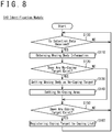
- the identification module 510 makes the processor 240 execute processes shown in Fig. 8 .
- the processor 240 determines whether detection data generated by the detection device 100 are received or not. When the detection data are not received (step S100: NO), the processor 240 waits until the detection data are received. When the detection data are received (step S100: YES), the processor 240 executes a process of a step S110.
- the processor 240 obtains information of a moving body detected by the detection device 100 from the detection data.
- the detection data includes information of the moving body detected by the detection device 100, such as a size, a shape, a location, a speed, a travelling direction or the like.
- the processor 240 obtains those pieces of information from the detection data.
- the processor 240 determines whether any no-coping target 20 exists or not among moving bodies detected by the detection device 100.
- the storage device 230 preliminary stores information of no-coping targets 20 such as a size, a shape, a flying speed, a flying route, a model, an affiliation or the like.
- the processor 240 compares information of the moving bodies obtained from the detection data and information of the no-coping targets 20 stored in the storage device 230. When information of a moving body obtained from the detection data matches information of a no-coping target 20 stored in the storage device 230, the processor 240 determines that this moving body corresponds to the no-coping target 20.
- the processor 240 may determine that this moving body corresponds to the no-coping target 20. Furthermore, a matching degree that indicates a degree of matching between information of a moving body and information of a no-coping target 20 may be calculated. When this matching degree is larger than a desired reference value, the processor 240 determines that the moving body corresponds to the no-coping target 20. When any moving body corresponding to a no-coping target 20 exists (step S120: YES), the processor 240 executes a process of a step S130. When no moving body corresponding to any no-coping target 20 exists (step S120: NO), the processor 240 executes a process of a step S150.
- the processor 240 sets the moving body, that is determined to correspond to a no-coping target 20, as a no-coping target 20.
- a setting of the no-coping area 12 is facilitated by setting the moving body as a no-coping target 20.
- the processor 240 sets the no-coping area 12 based on information of the moving body that is set as a no-coping target 20.
- the no-coping area 12 indicates an area where a distance from the no-coping target 20 is shorter than or equal to a desired distance.
- the no-coping area 12 may be an area where a distance from an outer edge of the no-coping target 20 is shorter than a desired distance.
- the no-coping area 12 may be an area where a distance from a center of the no-coping target 20 is shorter than a desired distance.
- the desired distance may be determined in accordance with a model of the no-coping target 20.
- the processor 240 determines whether any coping target 30 exists among the moving bodies detected by the detection device 100 or not.
- the processor 240 determines whether a moving body, that is not set as no-coping targets 20, corresponds to a coping target 30 or not, based on information of moving bodies obtained in the step S110.
- the processor 240 estimates a category of the moving body, such as a drone, a UAV or the like, from a size, a shape or the like of the moving body.
- the processor 240 calculates a threat level of the moving body based on the category, the speed and the travelling direction of the moving body. When the calculated threat level is higher than a desired reference value, the processor 240 determines that the moving body corresponds to a coping target 30.
- step S150: YES When any moving body corresponding to a coping target 30 exists (step S150: YES), the processor 240 executes a process of a step S160. When no moving body corresponding to a coping target 30 exists (step S150: NO), the processor 240 returns to the step S100 and repeats processes.
- the processor 240 registers the moving body that corresponds to a coping target 30 to a coping list 700 shown in Fig. 9 .
- the moving body registered to the coping list 700 corresponds to the coping target 30 to cope with.
- the coping list 700 stores, for example, an ID 701, an estimated category 702, a location 703, a speed 704, a threat level 705, a cope flag 706 and a suspend flag 707 of each moving body.
- the ID 701 is data to identify the moving body detected by the detection device 100.
- the estimated category 702 is data that indicates a category of the moving body estimated based on information of the moving body such as a size, a shape, a speed or the like.
- the location 703 is data that indicates a location of the moving body.
- the speed 704 is data that indicates a speed of the moving body and that indicates a travelling direction and a magnitude of the speed.
- the threat level 705 is data that indicates a degree to which the moving body affects defense facilities or the like. For example, the threat level 705 stores the threat level calculated in the step S150.
- the cope flag 706 is data that indicates that the cope target 30 is to preferentially cope with. The cope flag 706 is set when the corresponding coping target 30 is determined to be preferentially coped with.
- the suspend flag 707 is data that indicates that coping with the corresponding coping target 30 affects the no-coping area 12.
- a desired value for example: "1” is registered to the cope flag 706 and the suspend flag 707 when they are set and another value (for example: "0") is registered when the setting is canceled.
- the processor 240 returns to the step S100 and repeats processes.
- the identification module 510 identifies a no-coping target 20 and a coping target 30 and sets a no-coping area 12 in accordance with the no-coping target 20. It should be noted that the moving body identification means 512 executes the process of the step S100, the process of the step S110, the process of the step S120 and the process of the step S150.
- the no-coping area setting means 514 executes the process of the step S130 and the process of the step S140.
- the coping target registration means 516 executes the process of the step S160.
- the coping instruction module 520 makes the processor 240 execute processes shown in Fig. 10 .
- the processor 240 verifies whether any coping target 30 is registered to the coping list 700 or not.
- the processor 240 waits until a coping target 30 is registered.
- the processor 240 executes a process in a step S210.
- the processor 240 selects a coping target 30 to cope with from the coping list 700 based on a desired selection condition.
- the selection condition may include, for example, an earliest arrival to a predetermined location (for example, a location of a protected object).
- the processor 240 predicts a movement route of a coping target 30 registered to the coping list 700 and calculates an estimated arrival time when the coping target 30 reaches the protected obj ect based on the predicted movement route.
- a coping target 30 of which the calculated estimated arrival time is the earliest is selected.
- the selection condition may include a closest distance from a predetermined location such as the location of the protected object.
- the processor 240 calculates a distance from the location of the coping target 30 to the location of the protected object based on the location of the coping target 30 registered to the coping list 700. A coping target 30 of which the calculated distance is the shortest is selected.
- the selection condition may include a highest threat level 705 registered to the coping list 700.
- the processor 240 selects a coping target 30 of which the threat level 705 is the highest from the coping list 700.
- the selection condition may include a setting of the cope flag 706 registered to the coping list 700.
- the selection condition may include selecting a coping target 30 that is currently coped with.
- the storage device 230 stores data of the coping target 30 that is currently coped with, such as the ID 701.
- the processor 240 reads out data of the coping target 30 that is currently coped with from the storage device 230 and selects the coping target 30 that corresponds to the read data.
- the data that indicates the coping target 30 that is currently coped with may be included in the coping list 700.
- the selection condition may include a non-setting of the suspend flag 707 registered to the coping list 700.
- a coping target 30 of which the suspend flag 707 is not set a coping target 30 that affects the no-coping area 12 is excluded.
- the processor 204 may cancel the setting of the suspend flag 707 when a desired time has passed since it was set.
- the selection condition may be an arbitrary combination of the above-described selection conditions.
- the processor 240 may calculate a selection priority based on the above-described selection conditions and select a coping target 30 based on the calculated selection priority. For example: a first selection priority is set in accordance with an order of earlier estimated arrival time of reaching the protected object; a second selection priority is set in accordance with an order of higher threat level 705; and a selection priority as a whole is calculated based on this first selection priority and this second selection priority.
- the processor 240 may calculate a third selection priority based on a distance from a predetermined location to the location of the coping target 30 and calculate the selection priority as a whole based on the first selection priority, the second selection priority and the third selection priority.
- the first selection priority may be set in accordance with a time from a current time to the estimated arrival time.
- the second selection priority may be set in accordance with the threat level 705.
- the processor 240 calculates, in a step S220, an aiming point to cope with the selected coping target 30.
- the aiming point is calculated based on a performance of the threat coping device 300 and information of the coping target 30 such as a speed, a travelling direction or the like.
- the performance of the threat coping device 300 includes, for example, a range distance, a time from a start of coping to affecting the aiming point (for example, a time from launching an anti-aircraft missile to reaching the aiming point), or the like.
- a step S230 the processor 240 determines whether there is any influence to the no-coping area 12 by coping with the calculated aiming point or not.
- the processor 240 executes a process of a step S240 to cope with the coping target 30.
- the processor 240 executes a process of a step S260 to prohibit coping with the coping target 30. A method of determining whether there is any influence to the no-coping area 12 will be described later.
- the processor 240 sets a cope flag 706 corresponding to the selected coping target 30. For example, the processor 240 registers a predetermined value such as "1" to the cope flag 706 corresponding to the selected cope flag 706 in the coping list 700.
- the processor 240 In a step S250, the processor 240 generates a coping signal to cope with the selected coping target 30.
- the coping signal includes a signal that indicates information of the selected coping target 30.
- the coping signal includes a signal that indicates data included in the coping list 700.
- the coping signal includes a signal that indicates the ID 701, the location 703, the speed 704 and the like corresponding to the selected coping target 30.
- the processor 240 When the processor 240 generates the coping signal, the threat coping device 300 copes with the coping target 30 based on the coping signal. For this reason, the processor 240 stores data, that indicates that the threat coping device 300 is currently coping with the selected coping target 30, in the storage device 230. The processor 240 returns, after generating the coping signal, to the process of the step S200 and repeats processes.
- the processor 240 sets the suspend flag 707 corresponding to the selected coping target 30 in the step S260. For example, the processor 240 registers a predetermined value such as "1" to the suspend flag 707 corresponding to the selected coping target 30 in the coping list 700.
- a step S270 the processor 240 determines whether the threat coping device 300 is coping with the selected coping target 30 or not.
- the processor 240 reads out data of the coping target 30 which is currently coped with from the storage device 230.
- the processor 240 determines whether the threat coping device 300 is currently coping with the selected coping target 30, based on the read data.
- the processor 240 executes a process of a step S280 to suspend the coping.
- the processor 240 returns to the process of the step S210 and repeats processes.
- the processor 240 In the step S280, the processor 240 generates a suspension signal to suspend the coping with the selected coping target 30.
- the suspension signal may include a signal that indicates information of the selected coping target 30.
- the processor 240 returns, after generating the suspension signal, to the process of the step S210 and repeats processes.
- the coping instruction module 520 determines the coping target 30 with which the threat coping device 300 copes. In addition, the coping instruction module 520 suspends coping with the coping target 30 based on the no-coping area 12. It should be noted that the coping target selection means 522 executes the process of the step S200 and the process of the step S210. The aiming point calculation means 524 executes the process of the step S220. The coping instruction means 526 executes the processes of the steps S230 to S280.
- the coping program 600 makes the processor 340 of the threat coping device 300 execute processes shown in Fig. 11 .
- a step S300 the processor 340 verifies that the coping signal that indicates to cope with is received and that the suspension signal that indicates to suspend the coping is not received.
- the processor 340 executes a process of a step S310 to cope with the coping target 30.
- the processor 340 repeatedly executes the step S300.
- the processor 340 performs a coping with the coping target 30 based on the coping signal.
- the processor 340 obtains a current location of the coping target 30 to perform the coping with the coping target 30.
- the coping signal includes a signal that indicates information of the coping target 30 to cope with
- the processor 340 extracts information of the coping target 30 to cope with, such as a location of the coping target 30, from the coping signal.
- the processor 340 obtains the current location of the coping target 30 by use of the aiming sensor 350, based on the extracted location of the coping target 30.
- the processor 340 controls the aiming sensor 350 to detect a moving body that exists at the extracted location of the coping target 30.
- the processor 340 determines whether the detected moving body matches the coping target 30 or not and, in case of matching, copes with the detected moving body as the coping target 30. It should be noted that the current location of the coping target 30 may be obtained from the detection device 100.
- a step S320 the processor 340 determines whether the coping target 30 exists or not. For example, while the threat coping device 300 is coping with the coping target 30, the aiming sensor 350 continues detecting the coping target 30. When the aiming sensor 350 is detecting the coping target 30, the processor 340 determines that the coping target 30 exists. When it is determined that the coping target 30 exists (step S320: YES), the processor 340 returns to the process of the step S300 and repeats processes. When the aiming sensor 350 is not detecting the coping target 30, the processor 340 determines that the coping target 30 does not exist. When it is determined that the coping target 30 does not exist (step S320: NO), the processor 340 executes a process of a step S330.
- the processor 340 In the step S330, the processor 340 generates a deletion signal to delete a coping target 30 which has been coped from the coping list 700.
- a deletion signal includes, for example, a signal that indicates the ID 701 of the coping target 30 to delete.
- the control device 200 deletes, based on the deletion signal, the corresponding coping target 30 from the coping list 700.
- the processor 340 after generation of the deletion signal returns to the step S300 and repeats processes.
- the coping program 600 copes with a coping target 30 based on a coping signal from the control device 200 and performs suspension of coping based on a suspension signal from the control device 200. Therefore, the threat coping system 10 suppresses a coping with a coping target 30 that may affect a no-coping area 12 and can reduce misfiring to no-coping targets 20.
- a determination whether there is influence to a no-coping area 12 is performed based on a desired influence condition.
- the processor 240 determines that there is an influence to the no-coping area 12 when the threat coping device 300 copes with the coping target 30.
- the processor 240 determines that there is no influence to the no-coping area 12 even if the threat coping device 300 copes with the coping target 30.
- the influence condition includes an overlapping of a range of effect of a weapon with which the threat coping device 300 is provided to the no-coping area 12.
- a first threat coping device 300-1 affects a first range of effect 14-1
- a second threat coping device 300-2 affects a second range of effect 14-2.
- the first range of effect 14-1 does not overlap the no-coping area 12
- the second range of effect 14-2 overlaps the no-coping area 12
- the range of effect 14 includes a coping route (for example: line of fire) where a coping object (for example: light energy, electromagnetic energy, a bullet, a missile or the like) passes to defeat the coping target 30.
- This coping route is different depending on the weapon with which the threat coping device 300 is provided.
- the coping route 16 is extended on a straight line from the threat coping device 300 toward the aiming point.
- the coping route 16 is not extended on a straight line but includes a curve.
- the range of effect 14 when the coping route 16 is extended on a straight line, the range of effect 14 includes a conical area with the threat coping device 300 as an apex.
- An apex angle 18 of this range of effect 14 is different depending on the weapon with which the threat coping device 300 is provided. For this reason, the range of effect 14 may include a conical area having an apex angle 18 in accordance with the threat coping device 300.
- the influence condition may include a non-exceeding of an intensity of the irradiated energy beyond a predetermined value in the no-coping area 12.
- the influence condition may include a non-exceeding of laser intensity beyond a predetermined value in the no-coping area 12.
- the influence condition may include a non-exceeding of electric field strength beyond a predetermined value in the no-coping area 12.
- the influence condition may include a non-exceeding of an integrated value of energy irradiated to the no-coping area 12 beyond a predetermined value.
- the influence condition may include a non-exceeding of a probability in which a bullet reaches the no-coping area 12 beyond a predetermined value.
- the influence condition may include a non-overlapping of the range of effect 14, where there is an influence when an anti-aircraft missile hits the coping target 30, to the no-coping area 12.
- An anti-aircraft missile explodes and affects the surroundings when hitting the coping target 30.
- influence to the no-coping area 12 is reduced.
- the no-coping area 12 may be different depending on the no-coping target 20.
- the no-coping area 12 may be decided depending on a size and a speed of the no-coping target 20.
- the no-coping area 12 indicates an area where a distance from the no-coping target 20 is shorter than or equal to a desired distance.
- This desired distance may be decided depending to a length, a speed or the like of the no-coping target 20.
- the desired distance may be proportional to a length of the no-coping target 20. In other words, the longer the length of the no-coping target 20, the wider the no-coping area 12 may be set.
- the desired distance may be a value in which the length of the no-coping target 20 is multiplied by an arbitrary coefficient.
- L indicates a desired distance and C L indicates a length of the no-coping target 20.
- a 1 indicates a coefficient.
- the desired distance may be proportional to a speed of the no-coping target 20.
- the faster the speed of the no-coping target 20, the wider the no-coping area 12 may be set.
- the desired distance may be a value in which a speed of the no-coping target 20 is multiplied by an arbitrary coefficient.
- C v indicates a speed of the no-coping target 20.
- a 2 indicates a coefficient.
- the desired distance may be decided based on a value calculated based on a length of the no-coping target 20 and a value calculated based on a speed of the no-coping target 20.
- the desired distance may be a value in which two values are added, as shown in Equation (3).
- the no-coping area 12 may be decided based on a speed and a travelling direction of the no-coping target 20.
- the no-coping area 12 may be expanded in the travelling direction of the no-coping target 20 by a distance based on the speed of the no-coping target 20.
- the no-coping area 12 may be expanded at a location inclined by an angle ⁇ with respect to the travelling direction by a value in which the speed of the no-coping target 20 is multiplied by cos ⁇ and an arbitrary coefficient.
- the no-coping area 12 may be decided based on a distance corresponding to a length and a speed of the no-coping target 20 that are preliminarily registered.
- the storage device 230 stores a distance corresponding to the length and the speed of the no-coping target 20.
- the processor 240 reads out the corresponding distance from the storage device 230 based on the length and the speed of the no-coping target 20.
- the processor 240 sets an area where a distance from the no-coping target 20 is shorter than or equal to the read distance as the no-coping area 12.
- the storage device 230 may store a distance by which the no-coping area 12 is expanded in the travelling direction, in correspondence with the speed of the no-coping target 20.
- the processor 240 reads out the distance by which the no-coping area 12 is expanded from the storage device 230.
- the processor 240 expands the no-coping area 12 in accordance with the read distance.
- the no-coping area 12 may be different depending to the weapon with which the threat coping device 300 is provided. As shown in Fig. 15 , a first coping area 12-1 is set when the first threat coping device 300-1 copes, and a second coping area 12-2 is set when the second threat coping device 300-2 copes.
- the no-coping area 12 may be decided based on characteristics (for example, an aiming accuracy, an apex angle 18, a range of effect 14 when a coping object hits a coping target 30, or the like) of the weapon with which the threat coping device 300.
- the no-coping area 12 indicates an area where a distance from the no-coping target 20 is shorter than or equal to a desired distance.
- This desired distance may be decided depending to characteristics of the weapon with which the threat coping device 300 is provided. For example, as shown in Equation (4), the desired distance is decided based on a distance from the coping target 30 to the threat coping device 300 and the characteristics of the weapon with which the threat coping device 300 is provided.
- the processor 240 adds a value in which the aiming accuracy of the weapon with which the threat coping device 300 is provided is multiplied by a coefficient and a value in which the apex angle 18 is multiplied by a coefficient.
- the desired distance may be a value obtained by multiplying the value obtained by the addition and a distance from the coping target 30 to the threat coping device 300, as shown in Equation (4).
- D indicates the distance from the coping target 30 to the threat coping device 300.
- W 1 indicates the aiming accuracy and W 2 indicates the apex angle 18.
- B 1 and B 2 indicate the coefficients.
- the desired distance may be decided based on a range of effect when the coping object hits the coping target 30. For example, as shown in Equation (5), the desired distance may be further added with a value in which a size of the range of effect 14 when the coping object hits the coping target 30 is multiplied by a coefficient.
- W 3 indicates the size of the range of effect 14 when the coping object hits the coping target 30, and B 3 indicates the coefficient.
- the desired distance may be decided further based on a length of the no-coping target 20.
- the desired distance may be a value in which the value calculated based on the characteristics of the weapon with which the threat coping device 300 is provided is added with a value in which the length of the no-coping target 20 is multiplied by an arbitrary coefficient.
- the desired distance may be decided further based on a speed of the no-coping target 20.
- the desired distance may be a value added with a value in which the speed of the no-coping target 20 is multiplied by an arbitrary coefficient.
- the no-coping area 12 may be decided based on a speed and a travelling direction of the no-coping target 20.
- the no-coping area 12 may be expanded in the travelling direction of the no-coping target 20 by a distance based on the speed of the no-coping target 20.
- the no-coping area 12 may be expanded at a location inclined by an angle ⁇ with respect to the travelling direction, by a value in which the speed of the no-coping target 20 is multiplied by cos ⁇ and an arbitrary coefficient.
- the no-coping area 12 may be decided based on a distance registered in accordance with the threat coping device 300.
- the storage means 230 stores the distance corresponding to the threat coping device 300.
- the processor 240 reads out, based on the threat coping device 300 to set the no-coping area 12, the corresponding distance from the storage device 230.
- the processor 240 sets an area where a distance from the no-coping target 20 is shorter than or equal to the read distance, as the no-coping area 12.
- the storage device 230 may store a distance by which the no-coping area 12 is expanded in correspondence with the speed of the no-coping target 20.
- the processor 240 reads out the distance to expand the no-coping area 12 from the storage device 230.
- the processor 240 expands the no-coping area 12 in accordance with the read distance.
- the threat coping system 10 may be provided with a plurality of threat coping devices 300 (a first threat coping device 300-1, a second threat coping device 300-2, ..., a n-th threat coping device 300-n).
- the threat coping system 10 performs coping with one of detected coping targets 30, for example.
- n is a natural number larger than or equal to 2.
- the configuration of the control device 200 and the configuration of the threat coping device 300 are similar to the embodiment 1 and therefore descriptions thereof will be omitted.
- the assignment program 500 executed in the control device 200 is provided with the identification module 510 and the coping instruction module 520, similarly to the embodiment 1.
- the identification module 510 is similar to the embodiment 1 and therefore descriptions thereof will be omitted.
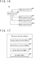
- the coping instruction module 520 is provided with the coping target selection means 522, the aiming point calculation means 524, the coping instruction means 526 and an assignment means 528.
- the coping target selection means 522, the aiming point calculation means 524 and the coping instruction means 526 function similarly to the embodiment 1.
- the assignment means 528 selects a threat coping device 300 to cope with the coping target 30 among the plurality of threat coping devices 300.
- the coping program 600 executed in the threat coping device 300 is similar to the embodiment 1 and therefore descriptions thereof will be omitted.
- the identification module 510 and the coping program 600 are similar to the embodiment 1 and therefore descriptions thereof will be omitted.
- the coping instruction module 520 makes the processor 240 execute processes shown in Fig. 18 .
- the process of the step S200 is similar to the embodiment 1 and therefore descriptions thereof will be omitted.
- the processor 240 selects the coping target 30 to cope with from the coping list 700, based on the desired selection condition.
- the selection condition may include a minimum number of the threat coping devices 300 that can cope with.
- the processor 240 obtains a state of the threat coping devices 300 such as locations and range from the threat coping devices 300.
- a number of the threat coping devices 300 that can cope with the coping target 30 is calculated based on the location of the coping target 30 and the locations and range of the threat coping devices 300.
- the processor 240 calculates a number of threat coping devices 300 of which the ranges include the location of the coping target 30.
- the coping target 30 of which the calculated number is the smallest is selected.
- the selection condition may include selection conditions of the embodiment 1.
- the processor 240 decides a threat coping device 300 to which the selected coping target 30 is assigned based on a desired assignment condition.
- the assignment condition may include, for example, assigning the coping target 30 to the closest threat coping device 300.
- the processor 240 obtains a state of the threat coping device 300, such as its location, from the threat coping device 300.
- the processor 240 compares distances from the location of the coping target 30 to the location of each threat coping device 300 to decide the threat coping device 300 to which the coping target 30 is assigned.
- the assignment condition may include a longest time for coping with.
- the processor 240 obtains a state of the threat coping device 300, such as its location and its range, from the threat coping device 300.
- the processor 240 predicts a moving route of the coping target 30 and calculates a coping time during which the coping target 30 passes through an area in the range of the threat coping device 300 when moving along the predicted route.
- the processor 240 assigns the coping target 30 to the threat coping device 300 of which the calculated coping time is the longest.
- the assignment condition may include a current assignment of the coping target 30.
- the storage device 230 stores data of the threat coping device 300 to which the coping target 30 is currently assigned.
- the processor 240 reads out data of the threat coping device 300 to which the coping target 30 is currently assigned from the storage device 230 and assigns the coping target 30 to the threat coping device 300 corresponding to the read data.
- Data of the currently assigned threat coping device 300 may be included in the coping list 700.
- the assignment condition may be an arbitrary combination of the above-described assignment conditions.
- the processor 240 may calculate an assignment priority based on the above-described assignment conditions and decides the threat coping device 300 to assign the coping target 30 based on the calculated assignment priority. For example: a first assignment priority is set in accordance with a distance from the location of the protected object to the location of the threat coping device 300; a second assignment priority is set in accordance with the time to cope with; and an assignment priority as a whole is calculated based on this first assignment priority and this second assignment priority.
- Processes from the step S220 to the step S280 are similar to the embodiment 1 and therefore descriptions thereof will be omitted.
- the threat coping system 10 can be provided with a plurality of threat coping devices 300.
- the threat coping system 10 may, when provided with a plurality of threat coping devices 300, cope with one of detected coping target 30 by use of a plurality of threat coping devices 300. This case is similar to the embodiment 1 and therefore description thereof will be omitted, except the coping list 700 shown in Fig. 9 and processes of the coping instruction module 520 shown in Fig. 10 .
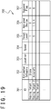
- the coping list 700 stores, for example, the ID 701, the estimated category 702, the location 703, the speed 704, the threat level 705, the suspend flag 707 and an assigned device 708 of each moving body.
- the assigned device 708 is data that indicates the threat coping device 300 assigned to the corresponding coping target 30. A plurality of values can be registered to the assigned device 708 to assign a single coping target 30 to a plurality of threat coping devices 300.
- the ID 701, the estimated category 702, the location 703, the speed 704, the threat level 705 and the suspend flag 707 that remain are similar to the embodiment 1 and therefore descriptions thereof will be omitted.
- the coping instruction module 520 makes the processor 240 execute processes similar to the processes shown in Fig. 18 , except the assignment of the coping target 30 to a plurality of threat coping devices 300.
- the step S200 and the step S210 are similar to the embodiment 2 and therefore descriptions thereof will be omitted.
- the processor 240 decides a plurality of threat coping devices 300 assigned to a selected coping target 30, based on a desired assignment condition. For example, a maximum value of a number of the threat coping devices 300 to decide is preliminarily decided.
- the assignment condition may include the assignment conditions in the embodiment 2.
- the processor 240 may select a desired number of threat coping devices 300 in order from a shorter distance from the location of the coping target 30 and assign the coping target 30 to the selected threat coping devices 300.
- a desired number of threat coping devices 300 may be selected in order from a longer time to cope with, and the coping target 30 may be assigned to the selected threat coping devices 300.
- the processor 240 may arbitrarily combine the assignment conditions to calculate an assignment priority and assign the coping target 30 to a plurality of threat coping devices 300 based on the calculated assignment priority.
- the processor 240 performs processes to each of the assigned threat coping devices 300. Details thereof are similar to the embodiment 2 and therefore descriptions thereof will be omitted.
- the threat coping system 10 can assign a single coping target 30 to a plurality of threat coping devices 300.
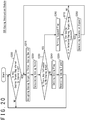
- the threat coping system 10 may, when provided with a plurality of threat coping devices 300, cope with a plurality of detected coping targets 30 by use of a plurality of threat coping devices 300. This case is similar to the embodiment 3 and therefore descriptions thereof will be omitted, except processes of the coping instruction module 520.
- the coping instruction module 520 makes the processor 240 execute processes shown in Fig. 20 .
- the processor 240 verifies whether any coping target 30 is registered to the coping list 700 or not.
- the processor 240 waits until a coping target 30 is registered.
- the processor 240 executes the process of the step S215.
- the processor 240 decides threat coping devices 300 to which the coping targets 30 registered to the coping list 700 are assigned, based on a desired assignment condition.
- the assignment condition may include a largest number of coping targets 30 which can be coped with.
- the processor 240 obtains states of the threat coping devices 300, such as locations and ranges, from the threat coping devices 300.
- the processor 240 assigns the coping targets 30 to the threat coping devices 300 so that a number of the coping targets 30 that can be coped with is the largest.
- the coping targets 30 may be assigned to the threat coping devices 300 based on performances of the threat coping devices 300 so that a number of coping targets 30 that can be defeated becomes the largest.
- the storage device 230 preliminarily stores the performances of the threat coping devices 300.
- the processor 240 reads out the performances of the threat coping devices 300 from the storage device 230 and assigns the coping targets 30 based on the read performances of the threat coping devices 300.
- the assignment condition may include the assignment conditions of the embodiment 3.
- the processor 240 may arbitrarily combine assignment conditions to calculate assignment priorities and assign coping targets 30 to the plurality of threat coping devices 300 based on the calculated assignment priorities.
- the processor 240 performs processes to each of the assigned threat coping devices 300. Details thereof are similar to the embodiment 2 and therefore descriptions thereof will be omitted.
- the threat coping system 10 can assign a plurality of threat coping devices 300 to a plurality of coping targets 30.
- the threat coping system 10 may, when provided with a plurality of threat coping devices 300, assign the detected coping target 30 to the threat coping devices 300 based on the no-coping area 12. This case is similar to the embodiment 2 and therefore descriptions thereof will be omitted, except processes of the coping instruction module 520.
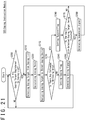
- the coping instruction module 520 makes the processor 240 execute processes shown in Fig. 21 .
- the processes in steps S200 to S210 are similar to the embodiment 2 and therefore descriptions thereof will be omitted.
- the processor 240 calculates the aiming point to cope with the selected coping target 30.
- the aiming point is calculated based on the performance of the threat coping devices 300 and information of the coping target 30 such as a speed, a travelling direction or the like.
- the performance of the threat coping devices 300 includes, for example, a range distance, a time from starting a coping to affecting the aiming point (for example, a time from firing of an anti-aircraft missile to reaching the aiming point) or the like.
- the processor 240 decides a plurality of threat coping devices 300 to which the selected coping target 30 is assigned, based on the no-coping area 12 and the desired assigning condition.
- the processor 240 extracts threat coping devices 300 that do not affect the no-coping area 12 even if they cope with the aiming point calculated in the step S220.
- a threat coping device 300 to which the coping target 30 is assigned is selected among the extracted threat coping devices 300.
- the assignment condition is similar to the embodiment 2 and therefore descriptions thereof will be omitted.
- the threat coping system 10 can assign the coping target 30 to the threat coping devices 300 based on the no-coping area 12.
- the processor 240 may change detection data of a moving body detected by the transponder receiver or the IFF. For example, the processor 240 may delete an affiliation detected by the IFF and change the affiliation to unknown.
- the processor 240 outputs the detection data of the moving body detected by the detection device 100 to the input output device 220.
- a user verifies the detection data outputted to the input output device 220, selects the moving body by using the input output device 220 and performs operation of deleting the affiliation data registered to the selected moving body.
- the processor 240 deletes the affiliation data registered to the selected moving body based on the deletion operation inputted to the input output device 220. By doing so, the threat coping system 10 can cope with moving body that has spoofed a transponder signal or an IFF signal.
- the processor 240 may determine whether any coping target 30 exists or not based on a feature of the moving body that the threat coping device 300 can cope with.
- the storage device 230 stores the feature of the moving body that the threat coping device 300 can cope with, such as a size, a shape, a category or the like.
- the processor 240 reads out the feature of the moving body that the threat coping device 300 can cope with from the storage device 230.
- the detection data of the moving body detected by the detection device 100 is compared to the feature of the moving body which is read out.
- the processor 240 determines, when the detected moving body is included in the moving bodies registered to the storage device 230, that this moving body corresponds to a coping target 30. As described above, it is determined whether any coping target 30 exists or not based on a feature of the moving body registered to the storage device 230. By comparing a feature of the moving body which the threat coping device 300 can cope with and a feature of the detected moving body, it is reduce to erroneously determine that a moving body that is not to be coped with corresponds to a coping target 30.
- a no-coping area 12 may include a fixed area.
- a no-coping area 12 may include a travelling route of a no-coping target 20 which is predetermined. A misfiring can be suppressed because an area where the threat coping device 300 copes with a coping target 30 is limited.
- processes in the steps S120 to S140 shown in Fig. 8 may be omitted when coping with a moving body in an area except a fixed area set as a no-coping area 12.
- an arbitrary body may be set as a no-coping target 20.
- a fixed body such as air facilities, private facilities or the like may be set as a no-coping target 20.
- a satellite orbiting on an orbit may be set as a no-coping target 20.
- the processor 240 may output information that indicates a location and a category of the coping target 30 to the input output device 220.
- the processor 240 may output information that indicates a no-coping area 12 that is set and locations of the threat coping devices 300 to the input output device 220.
- the input output device 220 may be provided with a display device that displays information to output. A user verifies the location of the coping target 30, the locations of the threat coping devices 300 and the no-coping area 12 that are outputted and uses the input output device 220 to select the threat coping device 300 to which the coping target 30 is to be assigned.
- the processor 240 assigns the coping target 30 to the threat coping device 300 based on the inputted data. As described above, the coping target 30 may be assigned in accordance with an input from a user. In addition, the processor 240 may calculate the threat coping device 300 to which a coping target 30 is to be assigned and output the calculation result as a recommended threat coping device 300 to the input output device 220.
- the processor 240 may wait for an input from the user before generating a coping signal.
- the processor 240 outputs verification information to verify whether coping with the coping target 30 can be performed, to the input output device 220.
- the user inputs a response to the verification information to the input output device 220.
- the processor 240 generates a coping signal based on the response inputted to the input output device 220.
- the processor 240 When the response inputted to the input output device 220 indicates an approval to the coping, the processor 240 generates a coping signal to perform the process of the step S200.
- the processor 240 When the response inputted to the input output device 220 indicates an interdiction to the coping, the processor 240 performs the process of the step S200 without generating any coping signal. As a result, it can be decided whether the threat coping device 300 copes with the coping target 30 or not in accordance with the input from the user. It should be noted that a coping by a plurality of threat coping device 300 may be approved and a coping by a single threat coping device 300 may be approved by a single input to the input output device 220.
- the threat coping system 10 may obtain data of a coping target 30 from an external device via a network.
- the communication device 210 of the control device 200 is wiredly or wirelessly connected to the external device that has data of the coping target 30 and obtains the data of the coping target 30 from the external device.
- the processor 240 of the control device 200 may use the data of the coping target 30 obtained from the external device to determine whether the moving body corresponds to the coping target 30 or not.
- the threat coping system 10 may obtain data of a no-coping target 20 from an external device via a network.
- the communication device 210 of the control device 200 is wiredly or wirelessly connected to the external device that has data of the no-coping target 20 and obtains the data of the no-coping target 20 from the external device.
- the processor 240 of the control device 200 may use the data of the no-coping target 20 obtained from the external device to determine whether a moving body corresponds to the no-coping target 20 or not.
- the processor 240 may set the no-coping area 12 based on the data of the no-coping target 20 obtained from the external device.
- the embodiments and variation examples described above are examples and may be modified within a range that does not inhibit functions.
- the described configurations of each of embodiments and variation examples may be modified withing a range that does not inhibit functions and/or may be arbitrarily combined.
- the aiming point calculation means 524 and the coping instruction means 526 of the coping instruction module 520 may be included in the coping program 600.
- the coping instruction module 520 executed by the control device 200 when performing the processes shown in Fig. 10 , the coping instruction module 520 executed by the control device 200 generates, in the step S210, a selection signal that indicates a selected coping target 30.
- the coping program 600 executed by the threat coping device 300 calculates, in the step S220 among the processes shown in Fig.
- the coping program 600 executes the processes in the steps S230 and later.
- the assignment program 500 may be executed by a plurality of processors 240 and a part or all of the assignment program 500 may be executed by the threat coping device 300.
- the threat coping system 10 may obtain information of the no-coping target 20 and information of the coping target 30 from outside. In this case, the control device 200 can cope with the coping target 30 by executing the no-coping area setting means 514 and the coping instruction means 526. If the detection device 100 and the threat coping device 300 are connected to the threat coping system 10, the detection device 100 and the threat coping device 300 may not be included in the threat coping system 10.
- a threat coping system described in each embodiment is understood for example as follows.
- a threat coping system is provided with a threat coping device (300) and a control device (200).
- the control device (200) is provided with a no-coping area setting means (514) and a coping instruction means (526).
- the no-coping area setting means (514) sets a no-coping area (12) based on information of a no-coping target which is not to cope with.
- the coping instruction means (526) generates an instruction signal that instructs the threat coping device to cope with the coping target, based on the no-coping area.
- a misfiring to a no-coping target is suppressed.
- a threat coping system is the threat coping system according to the first aspect and the no-coping area setting means (514) sets the no-coping area around a moving body identified as the no-coping target.
- the no-coping area may be an area of which a distance from the no-coping target is shorter than or equal to a desired distance.
- a threat coping system is the threat coping system according to the first aspect and is configured so that the no-coping area setting means (514) sets the no-coping area based on a length of the no-coping target.
- the threat coping system according to a fourth aspect is the threat coping system according to the first aspect and the no-coping area setting means (514) is configured to set the no-coping area based on a speed of the no-coping target.
- a no-coping area By setting a no-coping area based on a speed of a no-coping target, an area in accordance with the speed is set and misfiring to the no-coping target is suppressed.
- the faster the speed of the no-coping target the wider the no-coping area may be set.
- the no-coping area may be set to an area of which a distance from the no-coping target is shorter than or equal to a distance proportional to the speed of the no-coping target.
- the longer the length of the no-coping target the wider the no-coping area may be set.
- the no-coping area may be set to an area of which a distance from the no-coping target is shorter than or equal to a distance proportional to the length of the no-coping target.
- a threat coping system is the threat coping system according to the first aspect and is configured so that the no-coping area setting means (514) sets the no-coping area based on a travelling direction of the no-coping target (20).
- the no-coping area may be expanded in the travelling direction of the no-coping target based on the speed of the coping target.
- a threat coping system is the threat coping system according to the first aspect and is configured so that the no-coping area setting means (514) sets the no-coping area based on a feature of a weapon with which a threat coping device (300) is provided.
- the threat coping system can cope with the coping target in accordance to the feature of the weapon and therefore can perform the coping with the coping target with suppressing misfiring to the no-coping target.
- a threat coping system according to a seventh aspect is the threat coping system according to the sixth aspect and is configure so that the feature of the weapon with which the threat coping device is provided includes an aiming accuracy and an apex angle (18).
- the no-coping area By setting the no-coping area based on the aiming accuracy and the apex angle of the weapon, the no-coping area is set in accordance to a size of an area where the threat coping devices affects when coping with the coping target. For this reason, influence to the no-coping target may be suppressed.
- a threat coping system is the threat coping system according to the sixth aspect and is configured so that the feature of the weapon with which the threat coping device is provided includes a range of effect obtained when the weapon hits the moving body.
- a threat coping system is the threat coping system according to the first aspect and is configured so that the coping instruction means (526) generates a coping signal that instructs the threat coping device to cope when the threat coping device (300) does not affect the no-coping area by coping with the coping target (30).
- a threat coping system is the threat coping system according to the first aspect and is configured so that the coping instruction means (526) generates a suspension signal that instructs the threat coping device (300) to suspend coping when the threat coping device (300) affects the no-coping area (12) by coping with the coping target (30).
- an influence to the no-coping area may be reduced.
- a threat coping system is the threat coping system according to the ninth aspect and is configured so that the coping instruction means (526) determines that the threat coping device (300) affects the no-coping area (12) by coping with the coping target (30) when a range of effect (14) of coping by the threat coping device (300) overlaps the no-coping area (12).
- a threat coping system is the threat coping system according to the eleventh aspect and is configured so that the range of effect (14) includes a coping route (16) where a coping object for a weapon with which the threat coping device (300) is provided to destroy the coping target (30), passes.
- a threat coping system according to the thirteenth aspect is the threat coping system according to the eleventh aspect and is configured so that the range of effect (14) includes a conical area having an apex angle (18) in accordance with a weapon with which the threat coping device is provided when the coping route (16) is linearly extended.
Landscapes
- Engineering & Computer Science (AREA)
- Physics & Mathematics (AREA)
- Electromagnetism (AREA)
- General Physics & Mathematics (AREA)
- Remote Sensing (AREA)
- Radar, Positioning & Navigation (AREA)
- Computer Networks & Wireless Communication (AREA)
- General Engineering & Computer Science (AREA)
- Multimedia (AREA)
- Theoretical Computer Science (AREA)
- Aviation & Aerospace Engineering (AREA)
- Radar Systems Or Details Thereof (AREA)
- Aiming, Guidance, Guns With A Light Source, Armor, Camouflage, And Targets (AREA)
- Control Of Position, Course, Altitude, Or Attitude Of Moving Bodies (AREA)
Abstract
Description
- The present invention relates to a threat coping system.
- It is necessary to cope with attacks without notice such as terrorism. When a drone or an Unmanned Aerial Vehicle (UAV) is used in such an attack, it is necessary to cope with a drone or the like that is mixed with commercial aircrafts.
- For example,
Patent Literature 1 discloses a device for controlling headlight of vehicle. This device for controlling generates information on forward vehicle based on image information in which an image of an anterior area is captured and road information concerning a latent trouble when detecting a forward vehicle existing in the anterior area, and controls an irradiation area of the headlight according to the generated forward vehicle information. -
Patent Literature 2 discloses a light irradiation system that confirms safety of a target object, such as a person, to protect from reflection light or scattered light when irradiating laser. This light irradiation system determines a degree of safety of a target object for incident light based on a location of the target object and irradiation direction of the laser light. -
- [Patent Literature 1]
Japanese Patent No. 5626966 B2 - [Patent Literature 2]
Japanese Patent No. 6415882 B2 - In view of the above-described situation, an objective is to provide a threat coping system that suppress misfiring. Other objectives would be understood from the following disclosure and description of embodiments.
- A threat coping system according to an embodiment that is to achieve the above-mentioned objective is provided with a threat coping device that copes with a coping target and a control device that controls the threat coping device. The control device is provided with a no-coping area setting means and a coping instruction means. The no-coping area setting means sets a no-coping area based on information of a no-coping target that is not to cope with. The coping instruction means generates an instruction signal, that instructs the threat coping device to cope with a coping target, based on the no-coping area.
- According to the above-described embodiment, misfiring can be suppressed.
-
- [
Fig. 1] Fig. 1 is a schematic diagram to explain an overview of a threat coping system according to an embodiment. - [
Fig. 2] Fig. 2 is a configuration diagram of a control device according to an embodiment. - [
Fig. 3] Fig. 3 is a configuration diagram of a threat coping device according to an embodiment. - [
Fig. 4] Fig. 4 is a configuration diagram of an assignment program according to an embodiment. - [
Fig. 5] Fig. 5 is a configuration diagram of an identification module according to an embodiment. - [
Fig. 6] Fig. 6 is a configuration diagram of a coping instruction module according to an embodiment. - [
Fig. 7] Fig. 7 is a configuration diagram of a coping program according to an embodiment. - [
Fig. 8] Fig. 8 is a flowchart that shows processes executed by the identification module according to an embodiment. - [
Fig. 9] Fig. 9 is a diagram to explain a coping list according to an embodiment. - [
Fig. 10] Fig. 10 is a flowchart that shows processes executed by the coping instruction module according to an embodiment. - [
Fig. 11] Fig. 11 is a flowchart that shows processes executed by the coping program according to an embodiment. - [
Fig. 12] Fig. 12 is a diagram to explain a method to determine a presence or an absence of an influence to a no-coping area. - [
Fig. 13] Fig. 13 is a diagram to explain a range of effect by the threat coping device according to an embodiment. - [
Fig. 14] Fig. 14 is a diagram to explain a range of effect by the threat coping device according to an embodiment. - [
Fig. 15] Fig. 15 is a diagram to explain the no-coping area according to an embodiment. - [
Fig. 16] Fig. 16 is a configuration diagram of a threat coping system according to an embodiment. - [
Fig. 17] Fig. 17 is a configuration diagram of the coping instruction module according to an embodiment. - [
Fig. 18] Fig. 18 is a flowchart that shows processes executed by the coping instruction module according to an embodiment. - [
Fig. 19] Fig. 19 is a diagram to explain the coping list according to an embodiment. - [
Fig. 20] Fig. 20 is a flowchart that shows processes executed by the coping instruction module according to an embodiment. - [
Fig. 21] Fig. 21 is a flowchart that shows processes executed by the coping instruction module according to an embodiment. - As shown in
Fig. 1 , athreat coping system 10 according to an embodiment copes with coping targets 30 (including a first coping target 30-1 and a second coping target 30-2) that are a threat. Thethreat coping system 10 sets a no-coping area 12 around a no-coping target 20 that is not to cope with such as a passenger plane. Thethreat coping system 10 is configured to suppress influences to the no-coping area 12 when coping with thecoping targets 30. For this reason, thethreat coping system 10 does not cope with the first coping target 30-1 that exists in the no-coping area 12 and copes with the second coping target 30-2 that is outside the no-coping area 12, for example. Thecoping target 30 includes an Unmanned Aerial Vehicle (UAV), a drone and the like. - As a result, the
threat coping system 10 suppress damages to a no-copingtarget 20 when coping with copingtargets 30. Thethreat coping system 10 copes with thecoping targets 30 by use of devices such as a Direct-Energy Weapon (DEW), a machine gun, an anti-aircraft missile, for example. Those devices bring damages to moving bodies that exist around thecoping targets 30. For example, in case of a DEW, coping energy may penetrate through acoping target 30 and affect a moving body that exists behind thecoping target 30. In case of a machine gun, a bullet that missed acoping target 30 may affect a moving body that exists around thecoping target 30. In case of an anti-aircraft missile, an explosion of acoping target 30 may affect a moving body that exists around. Thethreat coping system 10 suppresses influence to surroundings due to coping with copingtargets 30 by setting a no-coping area 12. It should be noted that a DEW includes a laser weapon, a High-Power Microwave (HPM) weapon, an Electromagnetic Pulse (EMP) weapon, and the like. - The
threat coping system 10 is provided with adetection device 100, acontrol device 200 and athreat coping device 300. Thedetection device 100 detects a moving body around it and transmits detection data obtained by detection to thecontrol device 200. Thecontrol device 200 controls the threat copingdevice 300 and generates, based on the detection data, a coping signal that instructs to cope with acoping target 30. The threat copingdevice 300 copes with thecoping target 30 based on the coping signal. Thecontrol device 200 is electrically connected to thedetection device 100 and thethreat coping device 300, wiredly or wirelessly, to transmit and receive various data. - The
detection device 100 detects a moving body included in a preset detection area and generates detection data that indicates information of the detected moving body. The detection data include, for example, data that indicates a shape, a location, a speed, a travelling direction and the like of the moving body. Thedetection device 100 includes various sensors such as an optical camera, a Light Detection And Ranging (LIDAR), a radar device, a transponder receiver (for example, a device that receives a signal from an Air Traffic Control (ATC) transponder), an Identification Friend or Foe (IFF), for example. The optical camera, the LIDAR, the radar device and the transponder receiver detect for example a shape, a location, a speed, a travelling direction or the like of a moving body. The IFF detects for example an affiliation or the like of a moving body. - As shown in
Fig. 2 , thecontrol device 200 is provided with acommunication device 210, aninput output device 220, astorage device 230 and aprocessor 240. Thecontrol device 200 decides a copingtarget 30 to cope with based on the detection data generated by thedetection device 100 and instructs thethreat coping device 300 to cope with thedetermined coping target 30. - The
communication device 210 is connected to thedetection device 100 and thethreat coping device 300, and performs communication with thedetection device 100 and thethreat coping device 300. Thecommunication device 210 transfers data received from thedetection device 100 and thethreat coping device 300 to theprocessor 240. In addition, thecommunication device 210 transfers signals generated by theprocessor 240 to thedetection device 100 and thethreat coping device 300. Thecommunication device 210 includes, for example, various interfaces such as a Network Interface Card (NIC) and a Universal Serial Bus (USB). - The
input output device 220 receives information for theprocessor 240 to execute a process. In addition, theinput output device 220 outputs a result of the process executed by theprocessor 240. Theinput output device 220 includes a variety of input devices and output devices, and for example, includes a keyboard, a mouse, a microphone, a display, a speaker, a touch panel or the like. - The
storage device 230 stores various data to control thethreat coping device 300 such as anassignment program 500 and acoping list 700. Thestorage device 230 is used as a non-transitory tangible storage medium that stores theassignment program 500. Theassignment program 500 may be provided as a computer program product stored in a computer-readable recording medium 1, or may be provided as a computer program product downloadable from a server. - The
processor 240 performs various data processes to control thethreat coping device 300. Theprocessor 240 reads out theassignment program 500 from thestorage device 230 and executes it to generate a coping signal to cope with the copingtarget 30. For example, theprocessor 240 includes a Central Processing Unit (CPU) or the like. - As shown in
Fig. 3 , thethreat coping device 300 is provided with acommunication device 310, aninput output device 320, astorage device 330, aprocessor 340, an aimingsensor 350 and a copingexecution device 360. Thethreat coping device 300 copes with the copingtarget 30 based on the coping signal generated by thecontrol device 200. - The
communication device 310 is connected to thecontrol device 200 and performs communication with thecontrol device 200. Thecommunication device 310 transfers data received from thecontrol device 200 to theprocessor 340. In addition, thecommunication device 310 transfers a signal generated by theprocessor 340 to thecontrol device 200. Thecommunication device 310 includes, for example, various interfaces such as a NIC or a USB. In addition, thecommunication device 310 may be connected to thedetection device 100 and perform communication with thedetection device 100. - The
input output device 320 receives information for theprocessor 340 to execute a process. In addition, theinput output device 320 outputs a result of a process executed by theprocessor 340. Theinput output device 320 includes a variety of input devices and output devices, and for example includes a keyboard, a mouse, a microphone, a display, a speaker, a touch panel or the like. - The
storage device 330 stores various data to cope with the copingtarget 30, such as acoping program 600. Thestorage device 330 is used as a non-transitory tangible storage medium that stores thecoping program 600. Thecoping program 600 may be provided as a computer program product stored in a computer-readable recording medium 1, or may be provided as a computer program product downloadable from a server. Theassignment program 500 and thecoping program 600 may be stored indifferent recording media 1. - The
processor 340 performs various data processes to cope with the copingtarget 30. Theprocessor 340 reads out thecoping program 600 from thestorage device 330 and execute it. For example, theprocessor 340 includes a CPU or the like. - The aiming
sensor 350 is used when thethreat coping device 300 copes with the copingtarget 30. The aimingsensor 350 detects a location of the copingtarget 30 when thethreat coping device 300 copes with the copingtarget 30. Data that indicates the detected location is transmitted to theprocessor 340. - The coping
execution device 360 copes with the copingtarget 30 based on an instruction from theprocessor 340. For example, when the copingexecution device 360 is a DEW, energy is irradiated to the copingtarget 30. In addition, when the copingexecution device 360 is an anti-aircraft missile system, an anti-aircraft missile is launched to the copingtarget 30. When the copingexecution device 360 is a machine gun, bullets are fired to the copingtarget 30. - As shown in
Fig. 4 , theassignment program 500, that is executed in thecontrol device 200, is provided with anidentification module 510 and a copinginstruction module 520. Theidentification module 510 identifies a copingtarget 30 and a no-copingtarget 20 from the detected moving bodies, based on the detected data generated by thedetection device 100. In addition, theidentification module 510 sets a no-copingarea 12 based on the detection data of the identified no-copingtarget 20. The copinginstruction module 520 generates a coping signal to cope with the copingtarget 30, based on the detection data of the copingtarget 30 and the no-copingarea 12. - As shown in
Fig. 5 , theidentification module 510 is provided with a moving body identification means 512, a no-coping area setting means 514 and a coping target registration means 516. The moving body identification means 512 identifies a no-copingtarget 20 and a copingtarget 30 included in the moving bodies identified by thedetection device 100, based on the detection data generated by thedetection device 100. The no-coping area setting means 514 sets a no-copingarea 12 for a moving body identified as a no-copingtarget 20. The coping target registration means 516 registers information of a moving body, that is identified as a copingtarget 30, as a copingtarget 30 in thecoping list 700. - As shown in
Fig. 6 , the copinginstruction module 520 is provided with a coping target selection means 522, an aiming point calculation means 524 and a coping instruction means 526. The coping target selection means 522 selects a copingtarget 30 to cope with from thecoping list 700 in which coping targets 30 are registered. The aiming point calculation means 524 calculates an aiming point at a moment of coping with the selected copingtarget 30. The aiming point indicates, when coping by use of an anti-aircraft missile for example, a meeting point of the copingtarget 30 and the anti-aircraft missile. When coping by use of a DEW, the aiming point indicates a location where the energy is irradiated. The coping instruction means 526 determines whether to cope with the copingtarget 30 or not based on the calculated aiming point and the no-copingarea 12 set by theidentification module 510. The coping instruction means 526 generates, when it determined to cope with the copingtarget 30, a coping signal to cope with the copingtarget 30. - As shown in
Fig. 7 , thecoping program 600, that is executed in thethreat coping device 300, is provided with a coping means 610. The coping means 610 copes with the copingtarget 30 based on the coping signal generated by theassignment program 500. - The
identification module 510 makes theprocessor 240 execute processes shown inFig. 8 . In a step S100, theprocessor 240 determines whether detection data generated by thedetection device 100 are received or not. When the detection data are not received (step S100: NO), theprocessor 240 waits until the detection data are received. When the detection data are received (step S100: YES), theprocessor 240 executes a process of a step S110. - In the step S110, the
processor 240 obtains information of a moving body detected by thedetection device 100 from the detection data. The detection data includes information of the moving body detected by thedetection device 100, such as a size, a shape, a location, a speed, a travelling direction or the like. Theprocessor 240 obtains those pieces of information from the detection data. - In a step S120, the
processor 240 determines whether any no-copingtarget 20 exists or not among moving bodies detected by thedetection device 100. Thestorage device 230 preliminary stores information of no-copingtargets 20 such as a size, a shape, a flying speed, a flying route, a model, an affiliation or the like. Theprocessor 240 compares information of the moving bodies obtained from the detection data and information of the no-copingtargets 20 stored in thestorage device 230. When information of a moving body obtained from the detection data matches information of a no-copingtarget 20 stored in thestorage device 230, theprocessor 240 determines that this moving body corresponds to the no-copingtarget 20. In addition, when a portion of information of a moving body obtained from the detection data matches a portion of information of a no-copingtarget 20, theprocessor 240 may determine that this moving body corresponds to the no-copingtarget 20. Furthermore, a matching degree that indicates a degree of matching between information of a moving body and information of a no-copingtarget 20 may be calculated. When this matching degree is larger than a desired reference value, theprocessor 240 determines that the moving body corresponds to the no-copingtarget 20. When any moving body corresponding to a no-copingtarget 20 exists (step S120: YES), theprocessor 240 executes a process of a step S130. When no moving body corresponding to any no-copingtarget 20 exists (step S120: NO), theprocessor 240 executes a process of a step S150. - In the step S130, the
processor 240 sets the moving body, that is determined to correspond to a no-copingtarget 20, as a no-copingtarget 20. As the no-copingarea 12 moves in accordance with a move of this moving body, a setting of the no-copingarea 12 is facilitated by setting the moving body as a no-copingtarget 20. - In a step S140, the
processor 240 sets the no-copingarea 12 based on information of the moving body that is set as a no-copingtarget 20. The no-copingarea 12 indicates an area where a distance from the no-copingtarget 20 is shorter than or equal to a desired distance. For example, the no-copingarea 12 may be an area where a distance from an outer edge of the no-copingtarget 20 is shorter than a desired distance. In addition, the no-copingarea 12 may be an area where a distance from a center of the no-copingtarget 20 is shorter than a desired distance. The desired distance may be determined in accordance with a model of the no-copingtarget 20. - In a step S150, the
processor 240 determines whether any copingtarget 30 exists among the moving bodies detected by thedetection device 100 or not. Theprocessor 240 determines whether a moving body, that is not set as no-copingtargets 20, corresponds to a copingtarget 30 or not, based on information of moving bodies obtained in the step S110. Theprocessor 240 estimates a category of the moving body, such as a drone, a UAV or the like, from a size, a shape or the like of the moving body. Theprocessor 240 calculates a threat level of the moving body based on the category, the speed and the travelling direction of the moving body. When the calculated threat level is higher than a desired reference value, theprocessor 240 determines that the moving body corresponds to a copingtarget 30. When any moving body corresponding to a copingtarget 30 exists (step S150: YES), theprocessor 240 executes a process of a step S160. When no moving body corresponding to a copingtarget 30 exists (step S150: NO), theprocessor 240 returns to the step S100 and repeats processes. - In the step S160, the
processor 240 registers the moving body that corresponds to a copingtarget 30 to acoping list 700 shown inFig. 9 . The moving body registered to thecoping list 700 corresponds to the copingtarget 30 to cope with. Thecoping list 700 stores, for example, anID 701, an estimatedcategory 702, alocation 703, aspeed 704, athreat level 705, a copeflag 706 and a suspendflag 707 of each moving body. TheID 701 is data to identify the moving body detected by thedetection device 100. The estimatedcategory 702 is data that indicates a category of the moving body estimated based on information of the moving body such as a size, a shape, a speed or the like. Thelocation 703 is data that indicates a location of the moving body. Thespeed 704 is data that indicates a speed of the moving body and that indicates a travelling direction and a magnitude of the speed. Thethreat level 705 is data that indicates a degree to which the moving body affects defense facilities or the like. For example, thethreat level 705 stores the threat level calculated in the step S150. The copeflag 706 is data that indicates that the copetarget 30 is to preferentially cope with. The copeflag 706 is set when the corresponding copingtarget 30 is determined to be preferentially coped with. The suspendflag 707 is data that indicates that coping with the corresponding copingtarget 30 affects the no-copingarea 12. For example, a desired value (for example: "1") is registered to the copeflag 706 and the suspendflag 707 when they are set and another value (for example: "0") is registered when the setting is canceled. In the step S160, when the copingtarget 30 is registered to thecoping list 700, theprocessor 240 returns to the step S100 and repeats processes. - As described above, the
identification module 510 identifies a no-copingtarget 20 and a copingtarget 30 and sets a no-copingarea 12 in accordance with the no-copingtarget 20. It should be noted that the moving body identification means 512 executes the process of the step S100, the process of the step S110, the process of the step S120 and the process of the step S150. The no-coping area setting means 514 executes the process of the step S130 and the process of the step S140. The coping target registration means 516 executes the process of the step S160. - The coping
instruction module 520 makes theprocessor 240 execute processes shown inFig. 10 . In a step S200, theprocessor 240 verifies whether any copingtarget 30 is registered to thecoping list 700 or not. When no copingtarget 30 is registered to the coping list 700 (step S200: NO), theprocessor 240 waits until a copingtarget 30 is registered. When any copingtarget 30 is registered to the coping list 700 (step S200: YES), theprocessor 240 executes a process in a step S210. - In the step S210, the
processor 240 selects a copingtarget 30 to cope with from thecoping list 700 based on a desired selection condition. The selection condition may include, for example, an earliest arrival to a predetermined location (for example, a location of a protected object). In this case, theprocessor 240 predicts a movement route of a copingtarget 30 registered to thecoping list 700 and calculates an estimated arrival time when the copingtarget 30 reaches the protected obj ect based on the predicted movement route. A copingtarget 30 of which the calculated estimated arrival time is the earliest is selected. - The selection condition may include a closest distance from a predetermined location such as the location of the protected object. In this case, the
processor 240 calculates a distance from the location of the copingtarget 30 to the location of the protected object based on the location of the copingtarget 30 registered to thecoping list 700. A copingtarget 30 of which the calculated distance is the shortest is selected. - The selection condition may include a
highest threat level 705 registered to thecoping list 700. In this case, theprocessor 240 selects a copingtarget 30 of which thethreat level 705 is the highest from thecoping list 700. - The selection condition may include a setting of the cope
flag 706 registered to thecoping list 700. By selecting a copingtarget 30 of which the copeflag 706 is set, a copingtarget 30 that is determined to cope with can be preferably selected. - The selection condition may include selecting a coping
target 30 that is currently coped with. In this case, thestorage device 230 stores data of the copingtarget 30 that is currently coped with, such as theID 701. Theprocessor 240 reads out data of the copingtarget 30 that is currently coped with from thestorage device 230 and selects the copingtarget 30 that corresponds to the read data. The data that indicates the copingtarget 30 that is currently coped with may be included in thecoping list 700. - The selection condition may include a non-setting of the suspend
flag 707 registered to thecoping list 700. By selecting a copingtarget 30 of which the suspendflag 707 is not set, a copingtarget 30 that affects the no-copingarea 12 is excluded. In this case, the processor 204 may cancel the setting of the suspendflag 707 when a desired time has passed since it was set. - The selection condition may be an arbitrary combination of the above-described selection conditions. For example, the
processor 240 may calculate a selection priority based on the above-described selection conditions and select a copingtarget 30 based on the calculated selection priority. For example: a first selection priority is set in accordance with an order of earlier estimated arrival time of reaching the protected object; a second selection priority is set in accordance with an order ofhigher threat level 705; and a selection priority as a whole is calculated based on this first selection priority and this second selection priority. In addition, theprocessor 240 may calculate a third selection priority based on a distance from a predetermined location to the location of the copingtarget 30 and calculate the selection priority as a whole based on the first selection priority, the second selection priority and the third selection priority. In addition, the first selection priority may be set in accordance with a time from a current time to the estimated arrival time. The second selection priority may be set in accordance with thethreat level 705. - When the coping
target 30 is selected, theprocessor 240 calculates, in a step S220, an aiming point to cope with the selected copingtarget 30. The aiming point is calculated based on a performance of thethreat coping device 300 and information of the copingtarget 30 such as a speed, a travelling direction or the like. The performance of thethreat coping device 300 includes, for example, a range distance, a time from a start of coping to affecting the aiming point (for example, a time from launching an anti-aircraft missile to reaching the aiming point), or the like. - In a step S230, the
processor 240 determines whether there is any influence to the no-copingarea 12 by coping with the calculated aiming point or not. When there is no influence to the no-copingarea 12 by coping with the calculated aiming point (step S230: NO), theprocessor 240 executes a process of a step S240 to cope with the copingtarget 30. When there is an influence to the no-copingarea 12 by coping with the aiming point (step S230: YES), theprocessor 240 executes a process of a step S260 to prohibit coping with the copingtarget 30. A method of determining whether there is any influence to the no-copingarea 12 will be described later. - In the step S240, the
processor 240 sets a copeflag 706 corresponding to the selected copingtarget 30. For example, theprocessor 240 registers a predetermined value such as "1" to the copeflag 706 corresponding to the selected copeflag 706 in thecoping list 700. - In a step S250, the
processor 240 generates a coping signal to cope with the selected copingtarget 30. The coping signal includes a signal that indicates information of the selected copingtarget 30. For example, the coping signal includes a signal that indicates data included in thecoping list 700. In particular, the coping signal includes a signal that indicates theID 701, thelocation 703, thespeed 704 and the like corresponding to the selected copingtarget 30. When theprocessor 240 generates the coping signal, thethreat coping device 300 copes with the copingtarget 30 based on the coping signal. For this reason, theprocessor 240 stores data, that indicates that thethreat coping device 300 is currently coping with the selected copingtarget 30, in thestorage device 230. Theprocessor 240 returns, after generating the coping signal, to the process of the step S200 and repeats processes. - When there is an influence to the no-coping area 12 (step S230: YES), the
processor 240 sets the suspendflag 707 corresponding to the selected copingtarget 30 in the step S260. For example, theprocessor 240 registers a predetermined value such as "1" to the suspendflag 707 corresponding to the selected copingtarget 30 in thecoping list 700. - In a step S270, the
processor 240 determines whether thethreat coping device 300 is coping with the selected copingtarget 30 or not. Theprocessor 240 reads out data of the copingtarget 30 which is currently coped with from thestorage device 230. Theprocessor 240 determines whether thethreat coping device 300 is currently coping with the selected copingtarget 30, based on the read data. When thethreat coping device 300 is currently coping with the selected coping target 30 (step S270: YES), theprocessor 240 executes a process of a step S280 to suspend the coping. When thethreat coping device 300 is not currently coping with the selected coping target 30 (step S270: NO), theprocessor 240 returns to the process of the step S210 and repeats processes. - In the step S280, the
processor 240 generates a suspension signal to suspend the coping with the selected copingtarget 30. The suspension signal may include a signal that indicates information of the selected copingtarget 30. Theprocessor 240 returns, after generating the suspension signal, to the process of the step S210 and repeats processes. - As described above, the coping
instruction module 520 determines the copingtarget 30 with which thethreat coping device 300 copes. In addition, the copinginstruction module 520 suspends coping with the copingtarget 30 based on the no-copingarea 12. It should be noted that the coping target selection means 522 executes the process of the step S200 and the process of the step S210. The aiming point calculation means 524 executes the process of the step S220. The coping instruction means 526 executes the processes of the steps S230 to S280. - The
coping program 600 makes theprocessor 340 of thethreat coping device 300 execute processes shown inFig. 11 . In a step S300, theprocessor 340 verifies that the coping signal that indicates to cope with is received and that the suspension signal that indicates to suspend the coping is not received. When the coping signal is received and the suspension signal is not received (step S300: TRUE), theprocessor 340 executes a process of a step S310 to cope with the copingtarget 30. When the coping signal is not received or the suspension signal is received (step S300: FALSE), theprocessor 340 repeatedly executes the step S300. - In the step S310, the
processor 340 performs a coping with the copingtarget 30 based on the coping signal. Theprocessor 340 obtains a current location of the copingtarget 30 to perform the coping with the copingtarget 30. As the coping signal includes a signal that indicates information of the copingtarget 30 to cope with, theprocessor 340 extracts information of the copingtarget 30 to cope with, such as a location of the copingtarget 30, from the coping signal. Theprocessor 340 obtains the current location of the copingtarget 30 by use of the aimingsensor 350, based on the extracted location of the copingtarget 30. For example, theprocessor 340 controls the aimingsensor 350 to detect a moving body that exists at the extracted location of the copingtarget 30. Theprocessor 340 determines whether the detected moving body matches the copingtarget 30 or not and, in case of matching, copes with the detected moving body as the copingtarget 30. It should be noted that the current location of the copingtarget 30 may be obtained from thedetection device 100. - In a step S320, the
processor 340 determines whether the copingtarget 30 exists or not. For example, while thethreat coping device 300 is coping with the copingtarget 30, the aimingsensor 350 continues detecting the copingtarget 30. When the aimingsensor 350 is detecting the copingtarget 30, theprocessor 340 determines that the copingtarget 30 exists. When it is determined that the copingtarget 30 exists (step S320: YES), theprocessor 340 returns to the process of the step S300 and repeats processes. When the aimingsensor 350 is not detecting the copingtarget 30, theprocessor 340 determines that the copingtarget 30 does not exist. When it is determined that the copingtarget 30 does not exist (step S320: NO), theprocessor 340 executes a process of a step S330. - In the step S330, the
processor 340 generates a deletion signal to delete a copingtarget 30 which has been coped from thecoping list 700. A deletion signal includes, for example, a signal that indicates theID 701 of the copingtarget 30 to delete. Thecontrol device 200 deletes, based on the deletion signal, the corresponding copingtarget 30 from thecoping list 700. Theprocessor 340 after generation of the deletion signal returns to the step S300 and repeats processes. - As described above, the
coping program 600 copes with a copingtarget 30 based on a coping signal from thecontrol device 200 and performs suspension of coping based on a suspension signal from thecontrol device 200. Therefore, thethreat coping system 10 suppresses a coping with a copingtarget 30 that may affect a no-copingarea 12 and can reduce misfiring to no-copingtargets 20. - A determination whether there is influence to a no-coping
area 12 is performed based on a desired influence condition. When the influence condition is satisfied, theprocessor 240 determines that there is an influence to the no-copingarea 12 when thethreat coping device 300 copes with the copingtarget 30. When the influence condition is not satisfied, theprocessor 240 determines that there is no influence to the no-copingarea 12 even if thethreat coping device 300 copes with the copingtarget 30. - The influence condition includes an overlapping of a range of effect of a weapon with which the
threat coping device 300 is provided to the no-copingarea 12. In particular, as shown inFig. 12 , a first threat coping device 300-1 affects a first range of effect 14-1 and a second threat coping device 300-2 affects a second range of effect 14-2. As the first range of effect 14-1 does not overlap the no-copingarea 12, it is determined that there is no influence to the no-copingarea 12 even if the first threat coping device 300-1 copes with the copingtarget 30. On the other hand, as the second range of effect 14-2 overlaps the no-copingarea 12, it is determined that there is an influence to the no-copingarea 12 when the second threat coping device 300-2 copes with the copingtarget 30. - The range of
effect 14 includes a coping route (for example: line of fire) where a coping object (for example: light energy, electromagnetic energy, a bullet, a missile or the like) passes to defeat the copingtarget 30. This coping route is different depending on the weapon with which thethreat coping device 300 is provided. In case of a DEW, a machine gun or the like, as shown inFig. 13 , the copingroute 16 is extended on a straight line from thethreat coping device 300 toward the aiming point. In case of an anti-aircraft missile system or the like, as shown inFig. 14 , the copingroute 16 is not extended on a straight line but includes a curve. In addition, as shown inFig. 13 , when the copingroute 16 is extended on a straight line, the range ofeffect 14 includes a conical area with thethreat coping device 300 as an apex. Anapex angle 18 of this range ofeffect 14 is different depending on the weapon with which thethreat coping device 300 is provided. For this reason, the range ofeffect 14 may include a conical area having anapex angle 18 in accordance with thethreat coping device 300. - When the
threat coping device 300 is provided with a DEW, the influence condition may include a non-exceeding of an intensity of the irradiated energy beyond a predetermined value in the no-copingarea 12. For example, when thethreat coping device 300 is provided with a laser weapon, the influence condition may include a non-exceeding of laser intensity beyond a predetermined value in the no-copingarea 12. In addition, when thethreat coping device 300 is provided with a HPM weapon, the influence condition may include a non-exceeding of electric field strength beyond a predetermined value in the no-copingarea 12. In addition, the influence condition may include a non-exceeding of an integrated value of energy irradiated to the no-copingarea 12 beyond a predetermined value. - When the
threat coping device 300 is provided with a machine gun, the influence condition may include a non-exceeding of a probability in which a bullet reaches the no-copingarea 12 beyond a predetermined value. - When the
threat coping device 300 is provided with an anti-aircraft missile system, the influence condition may include a non-overlapping of the range ofeffect 14, where there is an influence when an anti-aircraft missile hits the copingtarget 30, to the no-copingarea 12. An anti-aircraft missile explodes and affects the surroundings when hitting the copingtarget 30. By not overlapping the affected area to the no-copingarea 12, influence to the no-copingarea 12 is reduced. - The no-coping
area 12 may be different depending on the no-copingtarget 20. For example, the no-copingarea 12 may be decided depending on a size and a speed of the no-copingtarget 20. In particular, the no-copingarea 12 indicates an area where a distance from the no-copingtarget 20 is shorter than or equal to a desired distance. This desired distance may be decided depending to a length, a speed or the like of the no-copingtarget 20. For example, the desired distance may be proportional to a length of the no-copingtarget 20. In other words, the longer the length of the no-copingtarget 20, the wider the no-copingarea 12 may be set. In particular, as shown in Equation (1), the desired distance may be a value in which the length of the no-copingtarget 20 is multiplied by an arbitrary coefficient. L indicates a desired distance and CL indicates a length of the no-copingtarget 20. A1 indicates a coefficient. -

- In addition, the desired distance may be proportional to a speed of the no-coping
target 20. In other words, the faster the speed of the no-copingtarget 20, the wider the no-copingarea 12 may be set. In particular, as shown in Equation (2), the desired distance may be a value in which a speed of the no-copingtarget 20 is multiplied by an arbitrary coefficient. Cv indicates a speed of the no-copingtarget 20. A2 indicates a coefficient. -

- In addition, the desired distance may be decided based on a value calculated based on a length of the no-coping
target 20 and a value calculated based on a speed of the no-copingtarget 20. For example, the desired distance may be a value in which two values are added, as shown in Equation (3). -

- As described above, by setting an area in accordance with a speed and a length of the no-coping
target 20 as the no-copingarea 12, misfiring to the no-copingtarget 20 is suppressed. - The no-coping
area 12 may be decided based on a speed and a travelling direction of the no-copingtarget 20. For example, the no-copingarea 12 may be expanded in the travelling direction of the no-copingtarget 20 by a distance based on the speed of the no-copingtarget 20. In particular, the no-copingarea 12 may be expanded at a location inclined by an angle θ with respect to the travelling direction by a value in which the speed of the no-copingtarget 20 is multiplied by cos θ and an arbitrary coefficient. - The no-coping
area 12 may be decided based on a distance corresponding to a length and a speed of the no-copingtarget 20 that are preliminarily registered. For example, thestorage device 230 stores a distance corresponding to the length and the speed of the no-copingtarget 20. Theprocessor 240 reads out the corresponding distance from thestorage device 230 based on the length and the speed of the no-copingtarget 20. Theprocessor 240 sets an area where a distance from the no-copingtarget 20 is shorter than or equal to the read distance as the no-copingarea 12. Furthermore, thestorage device 230 may store a distance by which the no-copingarea 12 is expanded in the travelling direction, in correspondence with the speed of the no-copingtarget 20. Theprocessor 240 reads out the distance by which the no-copingarea 12 is expanded from thestorage device 230. Theprocessor 240 expands the no-copingarea 12 in accordance with the read distance. - The no-coping
area 12 may be different depending to the weapon with which thethreat coping device 300 is provided. As shown inFig. 15 , a first coping area 12-1 is set when the first threat coping device 300-1 copes, and a second coping area 12-2 is set when the second threat coping device 300-2 copes. - The no-coping
area 12 may be decided based on characteristics (for example, an aiming accuracy, anapex angle 18, a range ofeffect 14 when a coping object hits a copingtarget 30, or the like) of the weapon with which thethreat coping device 300. In particular, the no-copingarea 12 indicates an area where a distance from the no-copingtarget 20 is shorter than or equal to a desired distance. This desired distance may be decided depending to characteristics of the weapon with which thethreat coping device 300 is provided. For example, as shown in Equation (4), the desired distance is decided based on a distance from the copingtarget 30 to thethreat coping device 300 and the characteristics of the weapon with which thethreat coping device 300 is provided. For example, theprocessor 240 adds a value in which the aiming accuracy of the weapon with which thethreat coping device 300 is provided is multiplied by a coefficient and a value in which theapex angle 18 is multiplied by a coefficient. The desired distance may be a value obtained by multiplying the value obtained by the addition and a distance from the copingtarget 30 to thethreat coping device 300, as shown in Equation (4). D indicates the distance from the copingtarget 30 to thethreat coping device 300. W1 indicates the aiming accuracy and W2 indicates theapex angle 18. B1 and B2 indicate the coefficients. -

- The desired distance may be decided based on a range of effect when the coping object hits the coping
target 30. For example, as shown in Equation (5), the desired distance may be further added with a value in which a size of the range ofeffect 14 when the coping object hits the copingtarget 30 is multiplied by a coefficient. W3 indicates the size of the range ofeffect 14 when the coping object hits the copingtarget 30, and B3 indicates the coefficient. -

- The desired distance may be decided further based on a length of the no-coping
target 20. For example, as shown in Equation (6), the desired distance may be a value in which the value calculated based on the characteristics of the weapon with which thethreat coping device 300 is provided is added with a value in which the length of the no-copingtarget 20 is multiplied by an arbitrary coefficient. -

- The desired distance may be decided further based on a speed of the no-coping
target 20. For example, as shown in Equation (7), the desired distance may be a value added with a value in which the speed of the no-copingtarget 20 is multiplied by an arbitrary coefficient. -

- The no-coping
area 12 may be decided based on a speed and a travelling direction of the no-copingtarget 20. For example, the no-copingarea 12 may be expanded in the travelling direction of the no-copingtarget 20 by a distance based on the speed of the no-copingtarget 20. In particular, the no-copingarea 12 may be expanded at a location inclined by an angle θ with respect to the travelling direction, by a value in which the speed of the no-copingtarget 20 is multiplied by cos θ and an arbitrary coefficient. - The no-coping
area 12 may be decided based on a distance registered in accordance with thethreat coping device 300. The storage means 230 stores the distance corresponding to thethreat coping device 300. Theprocessor 240 reads out, based on thethreat coping device 300 to set the no-copingarea 12, the corresponding distance from thestorage device 230. Theprocessor 240 sets an area where a distance from the no-copingtarget 20 is shorter than or equal to the read distance, as the no-copingarea 12. Furthermore, thestorage device 230 may store a distance by which the no-copingarea 12 is expanded in correspondence with the speed of the no-copingtarget 20. Theprocessor 240 reads out the distance to expand the no-copingarea 12 from thestorage device 230. Theprocessor 240 expands the no-copingarea 12 in accordance with the read distance. - As shown in
Fig. 16 , thethreat coping system 10 may be provided with a plurality of threat coping devices 300 (a first threat coping device 300-1, a second threat coping device 300-2, ..., a n-th threat coping device 300-n). Thethreat coping system 10 performs coping with one of detected copingtargets 30, for example. Here, n is a natural number larger than or equal to 2. The configuration of thecontrol device 200 and the configuration of thethreat coping device 300 are similar to theembodiment 1 and therefore descriptions thereof will be omitted. - The
assignment program 500 executed in thecontrol device 200 is provided with theidentification module 510 and the copinginstruction module 520, similarly to theembodiment 1. Theidentification module 510 is similar to theembodiment 1 and therefore descriptions thereof will be omitted. - As shown in
Fig. 17 , the copinginstruction module 520 is provided with the coping target selection means 522, the aiming point calculation means 524, the coping instruction means 526 and an assignment means 528. The coping target selection means 522, the aiming point calculation means 524 and the coping instruction means 526 function similarly to theembodiment 1. The assignment means 528 selects athreat coping device 300 to cope with the copingtarget 30 among the plurality ofthreat coping devices 300. - The
coping program 600 executed in thethreat coping device 300 is similar to theembodiment 1 and therefore descriptions thereof will be omitted. - The
identification module 510 and thecoping program 600 are similar to theembodiment 1 and therefore descriptions thereof will be omitted. - The coping
instruction module 520 makes theprocessor 240 execute processes shown inFig. 18 . The process of the step S200 is similar to theembodiment 1 and therefore descriptions thereof will be omitted. - In the step S210, similarly to the
embodiment 1, theprocessor 240 selects the copingtarget 30 to cope with from thecoping list 700, based on the desired selection condition. The selection condition may include a minimum number of thethreat coping devices 300 that can cope with. Theprocessor 240 obtains a state of thethreat coping devices 300 such as locations and range from thethreat coping devices 300. A number of thethreat coping devices 300 that can cope with the copingtarget 30 is calculated based on the location of the copingtarget 30 and the locations and range of thethreat coping devices 300. In other words, theprocessor 240 calculates a number ofthreat coping devices 300 of which the ranges include the location of the copingtarget 30. The copingtarget 30 of which the calculated number is the smallest is selected. - The selection condition may include selection conditions of the
embodiment 1. - In a step S215, the
processor 240 decides athreat coping device 300 to which the selected copingtarget 30 is assigned based on a desired assignment condition. The assignment condition may include, for example, assigning the copingtarget 30 to the closestthreat coping device 300. Theprocessor 240 obtains a state of thethreat coping device 300, such as its location, from thethreat coping device 300. Theprocessor 240 compares distances from the location of the copingtarget 30 to the location of eachthreat coping device 300 to decide thethreat coping device 300 to which the copingtarget 30 is assigned. - The assignment condition may include a longest time for coping with. The
processor 240 obtains a state of thethreat coping device 300, such as its location and its range, from thethreat coping device 300. Theprocessor 240 predicts a moving route of the copingtarget 30 and calculates a coping time during which the copingtarget 30 passes through an area in the range of thethreat coping device 300 when moving along the predicted route. Theprocessor 240 assigns the copingtarget 30 to thethreat coping device 300 of which the calculated coping time is the longest. - The assignment condition may include a current assignment of the coping
target 30. In this case, thestorage device 230 stores data of thethreat coping device 300 to which the copingtarget 30 is currently assigned. Theprocessor 240 reads out data of thethreat coping device 300 to which the copingtarget 30 is currently assigned from thestorage device 230 and assigns the copingtarget 30 to thethreat coping device 300 corresponding to the read data. Data of the currently assignedthreat coping device 300 may be included in thecoping list 700. - The assignment condition may be an arbitrary combination of the above-described assignment conditions. For example, the
processor 240 may calculate an assignment priority based on the above-described assignment conditions and decides thethreat coping device 300 to assign the copingtarget 30 based on the calculated assignment priority. For example: a first assignment priority is set in accordance with a distance from the location of the protected object to the location of thethreat coping device 300; a second assignment priority is set in accordance with the time to cope with; and an assignment priority as a whole is calculated based on this first assignment priority and this second assignment priority. - Processes from the step S220 to the step S280 are similar to the
embodiment 1 and therefore descriptions thereof will be omitted. - As described above, the
threat coping system 10 can be provided with a plurality ofthreat coping devices 300. - The
threat coping system 10 may, when provided with a plurality ofthreat coping devices 300, cope with one of detected copingtarget 30 by use of a plurality ofthreat coping devices 300. This case is similar to theembodiment 1 and therefore description thereof will be omitted, except thecoping list 700 shown inFig. 9 and processes of the copinginstruction module 520 shown inFig. 10 . - As shown in
Fig. 19 , thecoping list 700 stores, for example, theID 701, the estimatedcategory 702, thelocation 703, thespeed 704, thethreat level 705, the suspendflag 707 and an assigneddevice 708 of each moving body. The assigneddevice 708 is data that indicates thethreat coping device 300 assigned to thecorresponding coping target 30. A plurality of values can be registered to the assigneddevice 708 to assign asingle coping target 30 to a plurality ofthreat coping devices 300. TheID 701, the estimatedcategory 702, thelocation 703, thespeed 704, thethreat level 705 and the suspendflag 707 that remain are similar to theembodiment 1 and therefore descriptions thereof will be omitted. - The coping
instruction module 520 makes theprocessor 240 execute processes similar to the processes shown inFig. 18 , except the assignment of the copingtarget 30 to a plurality ofthreat coping devices 300. The step S200 and the step S210 are similar to theembodiment 2 and therefore descriptions thereof will be omitted. - In the step S215, the
processor 240 decides a plurality ofthreat coping devices 300 assigned to a selected copingtarget 30, based on a desired assignment condition. For example, a maximum value of a number of thethreat coping devices 300 to decide is preliminarily decided. The assignment condition may include the assignment conditions in theembodiment 2. For example, theprocessor 240 may select a desired number ofthreat coping devices 300 in order from a shorter distance from the location of the copingtarget 30 and assign the copingtarget 30 to the selectedthreat coping devices 300. In addition, a desired number ofthreat coping devices 300 may be selected in order from a longer time to cope with, and the copingtarget 30 may be assigned to the selectedthreat coping devices 300. Theprocessor 240 may arbitrarily combine the assignment conditions to calculate an assignment priority and assign the copingtarget 30 to a plurality ofthreat coping devices 300 based on the calculated assignment priority. - In the steps S220 to S280, the
processor 240 performs processes to each of the assignedthreat coping devices 300. Details thereof are similar to theembodiment 2 and therefore descriptions thereof will be omitted. - As described above, the
threat coping system 10 can assign asingle coping target 30 to a plurality ofthreat coping devices 300. - The
threat coping system 10 may, when provided with a plurality ofthreat coping devices 300, cope with a plurality of detected copingtargets 30 by use of a plurality ofthreat coping devices 300. This case is similar to theembodiment 3 and therefore descriptions thereof will be omitted, except processes of the copinginstruction module 520. - The coping
instruction module 520 makes theprocessor 240 execute processes shown inFig. 20 . In the step S200, theprocessor 240 verifies whether any copingtarget 30 is registered to thecoping list 700 or not. When no copingtarget 30 is registered to the coping list 700 (step S200: NO), theprocessor 240 waits until a copingtarget 30 is registered. When a copingtarget 30 is registered to the coping list 700 (step S200: YES), theprocessor 240 executes the process of the step S215. - In the step S215, the
processor 240 decidesthreat coping devices 300 to which the coping targets 30 registered to thecoping list 700 are assigned, based on a desired assignment condition. The assignment condition may include a largest number of coping targets 30 which can be coped with. Theprocessor 240 obtains states of thethreat coping devices 300, such as locations and ranges, from thethreat coping devices 300. Theprocessor 240 assigns the coping targets 30 to thethreat coping devices 300 so that a number of the coping targets 30 that can be coped with is the largest. - With respect to the assignment condition, the coping targets 30 may be assigned to the
threat coping devices 300 based on performances of thethreat coping devices 300 so that a number of coping targets 30 that can be defeated becomes the largest. Thestorage device 230 preliminarily stores the performances of thethreat coping devices 300. Theprocessor 240 reads out the performances of thethreat coping devices 300 from thestorage device 230 and assigns the coping targets 30 based on the read performances of thethreat coping devices 300. - The assignment condition may include the assignment conditions of the
embodiment 3. In addition, theprocessor 240 may arbitrarily combine assignment conditions to calculate assignment priorities and assign copingtargets 30 to the plurality ofthreat coping devices 300 based on the calculated assignment priorities. - In the steps S220 to S280, the
processor 240 performs processes to each of the assignedthreat coping devices 300. Details thereof are similar to theembodiment 2 and therefore descriptions thereof will be omitted. - As described above, the
threat coping system 10 can assign a plurality ofthreat coping devices 300 to a plurality of coping targets 30. - The
threat coping system 10 may, when provided with a plurality ofthreat coping devices 300, assign the detected copingtarget 30 to thethreat coping devices 300 based on the no-copingarea 12. This case is similar to theembodiment 2 and therefore descriptions thereof will be omitted, except processes of the copinginstruction module 520. - The coping
instruction module 520 makes theprocessor 240 execute processes shown inFig. 21 . The processes in steps S200 to S210 are similar to theembodiment 2 and therefore descriptions thereof will be omitted. - In the step S220, similarly to the
embodiment 2, theprocessor 240 calculates the aiming point to cope with the selected copingtarget 30. The aiming point is calculated based on the performance of thethreat coping devices 300 and information of the copingtarget 30 such as a speed, a travelling direction or the like. The performance of thethreat coping devices 300 includes, for example, a range distance, a time from starting a coping to affecting the aiming point (for example, a time from firing of an anti-aircraft missile to reaching the aiming point) or the like. - In the step S215, the
processor 240 decides a plurality ofthreat coping devices 300 to which the selected copingtarget 30 is assigned, based on the no-copingarea 12 and the desired assigning condition. Theprocessor 240 extractsthreat coping devices 300 that do not affect the no-copingarea 12 even if they cope with the aiming point calculated in the step S220. Based on desired assignment condition, athreat coping device 300 to which the copingtarget 30 is assigned is selected among the extractedthreat coping devices 300. The assignment condition is similar to theembodiment 2 and therefore descriptions thereof will be omitted. - The processes in the steps S230 to S280 are similar to the
embodiment 3 and therefore descriptions thereof will be omitted. - As described above, the
threat coping system 10 can assign the copingtarget 30 to thethreat coping devices 300 based on the no-copingarea 12. - When the
detection device 100 includes a transponder receiver or an IFF, theprocessor 240 may change detection data of a moving body detected by the transponder receiver or the IFF. For example, theprocessor 240 may delete an affiliation detected by the IFF and change the affiliation to unknown. Theprocessor 240 outputs the detection data of the moving body detected by thedetection device 100 to theinput output device 220. A user verifies the detection data outputted to theinput output device 220, selects the moving body by using theinput output device 220 and performs operation of deleting the affiliation data registered to the selected moving body. Theprocessor 240 deletes the affiliation data registered to the selected moving body based on the deletion operation inputted to theinput output device 220. By doing so, thethreat coping system 10 can cope with moving body that has spoofed a transponder signal or an IFF signal. - In the step S150 shown in
Fig. 8 , theprocessor 240 may determine whether any copingtarget 30 exists or not based on a feature of the moving body that thethreat coping device 300 can cope with. Thestorage device 230 stores the feature of the moving body that thethreat coping device 300 can cope with, such as a size, a shape, a category or the like. In the step S150, theprocessor 240 reads out the feature of the moving body that thethreat coping device 300 can cope with from thestorage device 230. The detection data of the moving body detected by thedetection device 100 is compared to the feature of the moving body which is read out. Theprocessor 240 determines, when the detected moving body is included in the moving bodies registered to thestorage device 230, that this moving body corresponds to a copingtarget 30. As described above, it is determined whether any copingtarget 30 exists or not based on a feature of the moving body registered to thestorage device 230. By comparing a feature of the moving body which thethreat coping device 300 can cope with and a feature of the detected moving body, it is reduce to erroneously determine that a moving body that is not to be coped with corresponds to a copingtarget 30. - A no-coping
area 12 may include a fixed area. For example, a no-copingarea 12 may include a travelling route of a no-copingtarget 20 which is predetermined. A misfiring can be suppressed because an area where thethreat coping device 300 copes with a copingtarget 30 is limited. In this case, processes in the steps S120 to S140 shown inFig. 8 may be omitted when coping with a moving body in an area except a fixed area set as a no-copingarea 12. - In addition, an arbitrary body may be set as a no-coping
target 20. For example, a fixed body such as air facilities, private facilities or the like may be set as a no-copingtarget 20. A satellite orbiting on an orbit may be set as a no-copingtarget 20. - In the step S215 (for example, the step S215 shown in
Fig. 18 ) of the copinginstruction module 520, theprocessor 240 may output information that indicates a location and a category of the copingtarget 30 to theinput output device 220. In addition, theprocessor 240 may output information that indicates a no-copingarea 12 that is set and locations of thethreat coping devices 300 to theinput output device 220. For example, theinput output device 220 may be provided with a display device that displays information to output. A user verifies the location of the copingtarget 30, the locations of thethreat coping devices 300 and the no-copingarea 12 that are outputted and uses theinput output device 220 to select thethreat coping device 300 to which the copingtarget 30 is to be assigned. When data that indicates thethreat coping device 300 to which the copingtarget 30 is to be assigned is inputted to theinput output device 220, theprocessor 240 assigns the copingtarget 30 to thethreat coping device 300 based on the inputted data. As described above, the copingtarget 30 may be assigned in accordance with an input from a user. In addition, theprocessor 240 may calculate thethreat coping device 300 to which acoping target 30 is to be assigned and output the calculation result as a recommendedthreat coping device 300 to theinput output device 220. - In the step S250 (for example, the step S250 shown in
Fig. 10 ) of the copinginstruction module 520, theprocessor 240 may wait for an input from the user before generating a coping signal. In the step S250, theprocessor 240 outputs verification information to verify whether coping with the copingtarget 30 can be performed, to theinput output device 220. The user inputs a response to the verification information to theinput output device 220. Theprocessor 240 generates a coping signal based on the response inputted to theinput output device 220. When the response inputted to theinput output device 220 indicates an approval to the coping, theprocessor 240 generates a coping signal to perform the process of the step S200. When the response inputted to theinput output device 220 indicates an interdiction to the coping, theprocessor 240 performs the process of the step S200 without generating any coping signal. As a result, it can be decided whether thethreat coping device 300 copes with the copingtarget 30 or not in accordance with the input from the user. It should be noted that a coping by a plurality ofthreat coping device 300 may be approved and a coping by a singlethreat coping device 300 may be approved by a single input to theinput output device 220. - The
threat coping system 10 may obtain data of a copingtarget 30 from an external device via a network. For example, thecommunication device 210 of thecontrol device 200 is wiredly or wirelessly connected to the external device that has data of the copingtarget 30 and obtains the data of the copingtarget 30 from the external device. In the step S150 shown inFig. 8 , theprocessor 240 of thecontrol device 200 may use the data of the copingtarget 30 obtained from the external device to determine whether the moving body corresponds to the copingtarget 30 or not. - The
threat coping system 10 may obtain data of a no-copingtarget 20 from an external device via a network. For example, thecommunication device 210 of thecontrol device 200 is wiredly or wirelessly connected to the external device that has data of the no-copingtarget 20 and obtains the data of the no-copingtarget 20 from the external device. In the step S120 shown inFig. 8 , theprocessor 240 of thecontrol device 200 may use the data of the no-copingtarget 20 obtained from the external device to determine whether a moving body corresponds to the no-copingtarget 20 or not. In addition, in the step S140, theprocessor 240 may set the no-copingarea 12 based on the data of the no-copingtarget 20 obtained from the external device. - The embodiments and variation examples described above are examples and may be modified within a range that does not inhibit functions. In addition, the described configurations of each of embodiments and variation examples may be modified withing a range that does not inhibit functions and/or may be arbitrarily combined. For example, the aiming point calculation means 524 and the coping instruction means 526 of the coping
instruction module 520 may be included in thecoping program 600. In this case, when performing the processes shown inFig. 10 , the copinginstruction module 520 executed by thecontrol device 200 generates, in the step S210, a selection signal that indicates a selected copingtarget 30. Thecoping program 600 executed by thethreat coping device 300 calculates, in the step S220 among the processes shown inFig. 10 , the aiming point based on the selection signal. Then thecoping program 600 executes the processes in the steps S230 and later. In addition, theassignment program 500 may be executed by a plurality ofprocessors 240 and a part or all of theassignment program 500 may be executed by thethreat coping device 300. In addition, thethreat coping system 10 may obtain information of the no-copingtarget 20 and information of the copingtarget 30 from outside. In this case, thecontrol device 200 can cope with the copingtarget 30 by executing the no-coping area setting means 514 and the coping instruction means 526. If thedetection device 100 and thethreat coping device 300 are connected to thethreat coping system 10, thedetection device 100 and thethreat coping device 300 may not be included in thethreat coping system 10. - A threat coping system described in each embodiment is understood for example as follows.
- A threat coping system according to a first aspect is provided with a threat coping device (300) and a control device (200). The control device (200) is provided with a no-coping area setting means (514) and a coping instruction means (526). The no-coping area setting means (514) sets a no-coping area (12) based on information of a no-coping target which is not to cope with. The coping instruction means (526) generates an instruction signal that instructs the threat coping device to cope with the coping target, based on the no-coping area.
- By setting a no-coping area by a no-coping area setting means, a misfiring to a no-coping target is suppressed.
- A threat coping system according to a second aspect is the threat coping system according to the first aspect and the no-coping area setting means (514) sets the no-coping area around a moving body identified as the no-coping target.
- The no-coping area may be an area of which a distance from the no-coping target is shorter than or equal to a desired distance.
- A threat coping system according to a third aspect is the threat coping system according to the first aspect and is configured so that the no-coping area setting means (514) sets the no-coping area based on a length of the no-coping target.
- The threat coping system according to a fourth aspect is the threat coping system according to the first aspect and the no-coping area setting means (514) is configured to set the no-coping area based on a speed of the no-coping target.
- By setting a no-coping area based on a speed of a no-coping target, an area in accordance with the speed is set and misfiring to the no-coping target is suppressed. In addition, the faster the speed of the no-coping target, the wider the no-coping area may be set. The no-coping area may be set to an area of which a distance from the no-coping target is shorter than or equal to a distance proportional to the speed of the no-coping target. In addition, the longer the length of the no-coping target, the wider the no-coping area may be set. The no-coping area may be set to an area of which a distance from the no-coping target is shorter than or equal to a distance proportional to the length of the no-coping target.
- A threat coping system according to a fifth aspect is the threat coping system according to the first aspect and is configured so that the no-coping area setting means (514) sets the no-coping area based on a travelling direction of the no-coping target (20).
- In addition, the no-coping area may be expanded in the travelling direction of the no-coping target based on the speed of the coping target.
- A threat coping system according to a sixth aspect is the threat coping system according to the first aspect and is configured so that the no-coping area setting means (514) sets the no-coping area based on a feature of a weapon with which a threat coping device (300) is provided.
- By setting the no-coping area based on a feature of a weapon with which the threat coping device is provided, the threat coping system can cope with the coping target in accordance to the feature of the weapon and therefore can perform the coping with the coping target with suppressing misfiring to the no-coping target.
- A threat coping system according to a seventh aspect is the threat coping system according to the sixth aspect and is configure so that the feature of the weapon with which the threat coping device is provided includes an aiming accuracy and an apex angle (18).
- By setting the no-coping area based on the aiming accuracy and the apex angle of the weapon, the no-coping area is set in accordance to a size of an area where the threat coping devices affects when coping with the coping target. For this reason, influence to the no-coping target may be suppressed.
- A threat coping system according to an eighth aspect is the threat coping system according to the sixth aspect and is configured so that the feature of the weapon with which the threat coping device is provided includes a range of effect obtained when the weapon hits the moving body.
- A threat coping system according to a ninth aspect is the threat coping system according to the first aspect and is configured so that the coping instruction means (526) generates a coping signal that instructs the threat coping device to cope when the threat coping device (300) does not affect the no-coping area by coping with the coping target (30).
- A threat coping system according to a tenth aspect is the threat coping system according to the first aspect and is configured so that the coping instruction means (526) generates a suspension signal that instructs the threat coping device (300) to suspend coping when the threat coping device (300) affects the no-coping area (12) by coping with the coping target (30).
- As the threat coping device suspends coping with the coping target, an influence to the no-coping area may be reduced.
- A threat coping system according to an eleventh aspect is the threat coping system according to the ninth aspect and is configured so that the coping instruction means (526) determines that the threat coping device (300) affects the no-coping area (12) by coping with the coping target (30) when a range of effect (14) of coping by the threat coping device (300) overlaps the no-coping area (12).
- A threat coping system according to a twelfth aspect is the threat coping system according to the eleventh aspect and is configured so that the range of effect (14) includes a coping route (16) where a coping object for a weapon with which the threat coping device (300) is provided to destroy the coping target (30), passes.
- A threat coping system according to the thirteenth aspect is the threat coping system according to the eleventh aspect and is configured so that the range of effect (14) includes a conical area having an apex angle (18) in accordance with a weapon with which the threat coping device is provided when the coping route (16) is linearly extended.
- The present application claims priority based on
Japanese Patent Application No. 2019-130595 filed on July 12, 2019
Claims (13)
- A threat coping system comprising:a threat coping device configured to cope with a coping target; anda control device configured to control the threat coping device,wherein the control device comprises:a no-coping area setting means configured to set a no-coping area based on information of a no-coping target which is not to cope with; anda coping instruction means configured to generate an instruction signal, that instructs the threat coping device to cope with the coping target, based on to the no-coping area.
- The threat coping system according to claim 1, wherein the no-coping area setting means is further configured to set the no-coping area around the no-coping target.
- The threat coping system according to claim 1 or 2, wherein the no-coping area setting means is further configured to set the no-coping area based on a length of the no-coping target.
- The threat coping system according to any one of claims 1 to 3, wherein the no-coping area setting means is further configured to set the no-coping area based on a speed of the no-coping target.
- The threat coping system according to any one of claims 1 to 4, wherein the no-coping area setting means is further configured to set the no-coping area based on a travelling direction of the no-coping target.
- The threat coping system according to any one of claims 1 to 5, wherein the no-coping area setting means is further configured to set the no-coping area based on a feature of a weapon which the threat coping device comprises.
- The threat coping system according to claim 6, wherein the feature of the weapon which the threat coping device comprises includes an aiming accuracy and an apex angle.
- The threat coping system according to claim 6 or 7, wherein the feature of the weapon which the threat coping device comprises includes a range of effect obtained when the weapon hits the coping target.
- The threat coping system according to any one of claims 1 to 8, wherein the coping instruction means is further configured to generate a coping signal, that instructs the threat coping device to cope, when the threat coping device does not affect the no-coping area by coping with the coping target.
- The threat coping system according to any one of claims 1 to 9, wherein the coping instruction means is further configured to generate a suspension signal, that instructs the threat coping device to suspend coping, when the threat coping device affects the no-coping area by coping with the coping target.
- The threat coping system according to claim 9 or 10, wherein the coping instruction means is further configured to determine that the threat coping device affects the no-coping area by coping with the coping target when a range of effect of coping by the threat coping device overlaps the no-coping area.
- The threat coping system according to claim 11, wherein the range of effect includes a coping route where a coping object for a weapon that the threat coping device comprises to destroy the coping target, passes.
- The threat coping system according to claim 12, wherein the range of effect includes a conical area having an apex angle in accordance with a weapon which the threat coping device comprises when the coping route is linearly extended.
Applications Claiming Priority (2)
| Application Number | Priority Date | Filing Date | Title |
|---|---|---|---|
| JP2019130595A JP7242461B2 (en) | 2019-07-12 | 2019-07-12 | threat response system |
| PCT/JP2020/006078 WO2021009955A1 (en) | 2019-07-12 | 2020-02-17 | Threat-coping system |
Publications (2)
| Publication Number | Publication Date |
|---|---|
| EP3926291A1 true EP3926291A1 (en) | 2021-12-22 |
| EP3926291A4 EP3926291A4 (en) | 2022-06-01 |
Family
ID=74210534
Family Applications (1)
| Application Number | Title | Priority Date | Filing Date |
|---|---|---|---|
| EP20841248.6A Pending EP3926291A4 (en) | 2019-07-12 | 2020-02-17 | Threat-coping system |
Country Status (4)
| Country | Link |
|---|---|
| US (1) | US12253603B2 (en) |
| EP (1) | EP3926291A4 (en) |
| JP (1) | JP7242461B2 (en) |
| WO (1) | WO2021009955A1 (en) |
Families Citing this family (8)
| Publication number | Priority date | Publication date | Assignee | Title |
|---|---|---|---|---|
| JP7242461B2 (en) * | 2019-07-12 | 2023-03-20 | 三菱重工業株式会社 | threat response system |
| JP7767018B2 (en) * | 2021-03-15 | 2025-11-11 | 株式会社東芝 | Missile monitoring system, method, and program |
| JP7724129B2 (en) * | 2021-10-14 | 2025-08-15 | 川崎重工業株式会社 | Laser Irradiation System |
| JP7847963B2 (en) * | 2021-10-15 | 2026-04-20 | 三菱重工業株式会社 | Threat management systems and threat management programs |
| JP7844132B2 (en) | 2021-10-27 | 2026-04-13 | 三菱重工業株式会社 | Threat mitigation systems and threat mitigation methods |
| KR20230154607A (en) * | 2022-05-02 | 2023-11-09 | 한국전자통신연구원 | Apparatus for information fusion/operation control for anti drone, anti drone system, and operation metohd therefor |
| GB2636175A (en) * | 2023-12-01 | 2025-06-11 | Raytheon Systems Ltd | Air/space object deconfliction tool for laser directed energy weapons |
| CN119063582B (en) * | 2024-11-05 | 2025-02-07 | 浙江大学海南研究院 | Mobile laser denial defense system |
Family Cites Families (60)
| Publication number | Priority date | Publication date | Assignee | Title |
|---|---|---|---|---|
| JPS5475098A (en) | 1977-11-25 | 1979-06-15 | Matsushita Electric Ind Co Ltd | Varister |
| JPS5626966U (en) | 1979-08-07 | 1981-03-12 | ||
| JPS56118103A (en) | 1980-02-25 | 1981-09-17 | Meidensha Electric Mfg Co Ltd | Man-machine controller |
| JPH0720461Y2 (en) | 1987-07-08 | 1995-05-15 | 三菱電機株式会社 | solenoid valve |
| US9121669B1 (en) * | 1994-09-02 | 2015-09-01 | The Boeing Company | System and method for designating a target for a remote aerial vehicle |
| JPH1163888A (en) * | 1997-08-08 | 1999-03-05 | Mitsubishi Electric Corp | Companion device |
| JPH11118393A (en) * | 1997-10-13 | 1999-04-30 | Mitsubishi Electric Corp | Flying object distribution status display device |
| JP2004506912A (en) * | 2000-08-16 | 2004-03-04 | レイセオン・カンパニー | Highly integrated single-substrate MMW multi-beam sensor |
| US6609597B1 (en) * | 2002-02-06 | 2003-08-26 | Enertrols, Inc. | Dampening apparatus |
| US7002127B2 (en) * | 2002-07-19 | 2006-02-21 | Lockheed Corp | Method and system for wavefront compensation |
| US6796213B1 (en) | 2003-05-23 | 2004-09-28 | Raytheon Company | Method for providing integrity bounding of weapons |
| US7328644B2 (en) * | 2005-07-12 | 2008-02-12 | Scv Quality Solutions, Llc | System and method for intercepting a projectile |
| IL190197A (en) * | 2008-03-17 | 2013-05-30 | Yoav Turgeman | Method for performing exo-atmospheric missile's interception trial |
| US8274424B2 (en) * | 2009-02-26 | 2012-09-25 | Raytheon Company | Integrated airport domain awareness response system, system for ground-based transportable defense of airports against manpads, and methods |
| IL201681A (en) * | 2009-10-22 | 2014-06-30 | Abraham Abershitz | Uav system and method |
| JP5626966B2 (en) | 2010-05-28 | 2014-11-19 | 株式会社小糸製作所 | Control device for vehicle headlamp, vehicle headlamp system |
| JP5554206B2 (en) | 2010-10-25 | 2014-07-23 | 三菱電機株式会社 | Thermal power distribution device |
| US8833231B1 (en) | 2012-01-22 | 2014-09-16 | Raytheon Company | Unmanned range-programmable airburst weapon system for automated tracking and prosecution of close-in targets |
| US9170070B2 (en) * | 2012-03-02 | 2015-10-27 | Orbital Atk, Inc. | Methods and apparatuses for active protection from aerial threats |
| US11313650B2 (en) * | 2012-03-02 | 2022-04-26 | Northrop Grumman Systems Corporation | Methods and apparatuses for aerial interception of aerial threats |
| IL228921B (en) * | 2012-10-17 | 2018-11-29 | Ziv Dan | An active protection system |
| US8939081B1 (en) * | 2013-01-15 | 2015-01-27 | Raytheon Company | Ladar backtracking of wake turbulence trailing an airborne target for point-of-origin estimation and target classification |
| JP6415882B2 (en) | 2014-07-24 | 2018-10-31 | 三菱重工業株式会社 | Safety confirmation device, light irradiation system, safety confirmation method, and safety confirmation program |
| DE102014014117A1 (en) * | 2014-09-24 | 2016-03-24 | Diehl Bgt Defence Gmbh & Co. Kg | A defense device for controlling an unmanned aerial vehicle, a protective device for controlling an unmanned aerial vehicle, and a method for operating a protective device |
| US9715009B1 (en) * | 2014-12-19 | 2017-07-25 | Xidrone Systems, Inc. | Deterent for unmanned aerial systems |
| WO2017013417A1 (en) * | 2015-07-17 | 2017-01-26 | Relmatech Limited | An aircraft controlled by a secure integrated airspace management system |
| DE102015011058A1 (en) | 2015-08-27 | 2017-03-02 | Rheinmetall Waffe Munition Gmbh | Threat prevention system |
| US11488385B2 (en) * | 2015-09-23 | 2022-11-01 | Dedrone Holdings, Inc. | Identifying, tracking, and disrupting unmanned aerial vehicles |
| JP2017072557A (en) | 2015-10-09 | 2017-04-13 | 三菱重工業株式会社 | Flight object detection system and flight object detection method |
| DE102016003238A1 (en) * | 2016-03-16 | 2017-09-21 | Diehl Defence Gmbh & Co. Kg | A method of controlling a missile to a flying target |
| US10073454B2 (en) * | 2016-03-17 | 2018-09-11 | Northrop Grumman Systems Corporation | Machine vision enabled swarm guidance technology |
| US9671200B1 (en) * | 2016-04-06 | 2017-06-06 | Northrop Grumman Systems Corporation | Kinetic air defense |
| IL264735B2 (en) * | 2016-08-14 | 2024-01-01 | Iron Drone Ltd | Flight planning system and methods for interceptor vehicles |
| US20190009904A1 (en) * | 2017-07-07 | 2019-01-10 | Walmart Apollo, Llc | Systems and methods for facilitating safe emergency landings of unmanned aerial vehicles |
| US10907940B1 (en) * | 2017-12-12 | 2021-02-02 | Xidrone Systems, Inc. | Deterrent for unmanned aerial systems using data mining and/or machine learning for improved target detection and classification |
| WO2019159159A1 (en) * | 2018-02-19 | 2019-08-22 | Robert Levy | Protective cable nets system (pcns) |
| IL258077B (en) * | 2018-03-13 | 2021-02-28 | Elta Systems Ltd | Drone interceptor system, and methods and computer program products useful in conjunction therewith |
| US20200341117A1 (en) * | 2019-04-23 | 2020-10-29 | Psionic, Llc | Navigation system for GPS denied environments |
| US10767953B2 (en) * | 2018-06-11 | 2020-09-08 | Tony Mitchell Cole | Automatic variable choke punt gun for swarm defense |
| US11879705B2 (en) * | 2018-07-05 | 2024-01-23 | Mikael Bror Taveniku | System and method for active shooter defense |
| US10922982B2 (en) * | 2018-08-10 | 2021-02-16 | Guardian Robotics, Inc. | Active shooter response drone |
| US11465741B2 (en) * | 2018-10-03 | 2022-10-11 | Sarcos Corp. | Deployable aerial countermeasures for neutralizing and capturing target aerial vehicles |
| US11472550B2 (en) * | 2018-10-03 | 2022-10-18 | Sarcos Corp. | Close proximity countermeasures for neutralizing target aerial vehicles |
| US11697497B2 (en) * | 2018-10-03 | 2023-07-11 | Sarcos Corp. | Aerial vehicles having countermeasures deployed from a platform for neutralizing target aerial vehicles |
| US10703451B1 (en) * | 2018-12-22 | 2020-07-07 | Richard D Adams | Countermeasures apparatus and method |
| US20220157060A1 (en) * | 2019-02-27 | 2022-05-19 | Telme Electronics Co., Ltd. | Multi-tod surround camera device for detecting drone intrusion, and drone intrusion detection and capture method using same |
| JP6537755B1 (en) | 2019-03-18 | 2019-07-03 | カルソニックカンセイ株式会社 | Method of manufacturing double pipe |
| EP3731198B1 (en) * | 2019-04-24 | 2024-03-20 | Minimax Viking Research & Development GmbH | Fire protection robot for control of fire protection devices, corresponding fire protection system and method for operating the same |
| US11385659B2 (en) * | 2019-05-17 | 2022-07-12 | Anduril Industries, Inc. | Counter drone system |
| AU2020303855B2 (en) * | 2019-06-26 | 2026-04-02 | Orica International Pte Ltd | Deployment of quasi-planar shock wave generators in association with seismic exploration |
| EP3833927A4 (en) * | 2019-07-12 | 2022-06-08 | Leonardo Electronics US Inc. | METHOD AND SYSTEM FOR OBSCURING AND REMOVAL OF ELECTRONIC WAR ASSETS FROM ENEMY DEFENSES |
| JP7242461B2 (en) * | 2019-07-12 | 2023-03-20 | 三菱重工業株式会社 | threat response system |
| RU2755603C2 (en) * | 2019-09-30 | 2021-09-17 | Акционерное общество "Лаборатория Касперского" | System and method for detecting and countering unmanned aerial vehicles |
| US12120595B2 (en) * | 2020-05-01 | 2024-10-15 | Intel Corporation | Satellite 5G terrestrial and non-terrestrial network interference exclusion zones |
| JP7466820B2 (en) * | 2020-05-29 | 2024-04-15 | パナソニックオートモーティブシステムズ株式会社 | Radar device, radar system, and object determination method |
| US20230088169A1 (en) * | 2020-11-08 | 2023-03-23 | Noam Kenig | System and methods for aiming and guiding interceptor UAV |
| US11594141B1 (en) * | 2022-01-19 | 2023-02-28 | King Abdulaziz University | System and methods to neutralize an attacking UAV based on acoustic features |
| US12366434B2 (en) * | 2022-02-22 | 2025-07-22 | Sony Group Corporation | Apparatus and method for defending a predetermined area from an autonomously moving unmanned aerial vehicle |
| US12266169B2 (en) * | 2022-07-06 | 2025-04-01 | The Boeing Company | Automated change assessment of target objects during a dynamic ISR mission |
| US20240286774A1 (en) * | 2023-02-24 | 2024-08-29 | Alan Taylor | Unmanned aerial vehicle, control method, and unmanned aerial vehicle defense system |
-
2019
- 2019-07-12 JP JP2019130595A patent/JP7242461B2/en active Active
-
2020
- 2020-02-17 EP EP20841248.6A patent/EP3926291A4/en active Pending
- 2020-02-17 US US17/441,342 patent/US12253603B2/en active Active
- 2020-02-17 WO PCT/JP2020/006078 patent/WO2021009955A1/en not_active Ceased
Also Published As
| Publication number | Publication date |
|---|---|
| WO2021009955A1 (en) | 2021-01-21 |
| US20220163670A1 (en) | 2022-05-26 |
| EP3926291A4 (en) | 2022-06-01 |
| JP7242461B2 (en) | 2023-03-20 |
| JP2021014958A (en) | 2021-02-12 |
| US12253603B2 (en) | 2025-03-18 |
Similar Documents
| Publication | Publication Date | Title |
|---|---|---|
| EP3926291A1 (en) | Threat-coping system | |
| EP2693160B1 (en) | Devices, systems and method to calculate and display a no-fly zone. | |
| US20090173788A1 (en) | system and method for prioritizing visually aimed threats for laser-based countermeasure engagement | |
| US20110196551A1 (en) | System and method for situation specific generation and assessment of risk profiles and start of suitable action for protection of vehicles | |
| KR102296962B1 (en) | Method and system for defending an anti- drone | |
| KR20220030242A (en) | Dynamic weapon-target assignment using a control-based methodology | |
| US12024282B2 (en) | Guidance device, flying object, air defense system and guidance program | |
| US20170328686A1 (en) | Visual disruption network and system, method, and computer program product thereof | |
| KR102376867B1 (en) | Method and apparatus for providing a dummy target to protect a vehicle and/or object from a radar guided tracking head | |
| KR101978494B1 (en) | Apparatus and method for controling guided missile attachable to drone | |
| US20190072962A1 (en) | Drone for collecting and providing image material for bomb damage assessment and air-to-ground armament system having same | |
| EP3055638B1 (en) | Missile system including ads-b receiver | |
| KR101877224B1 (en) | Method And Apparatus for Neutralizing Unmanned Aerial Vehicle | |
| US20190383923A1 (en) | Coordinated Searching Of An Airspace | |
| JP5013949B2 (en) | Rocket tracking radar device | |
| US20190249957A1 (en) | Command control system, interceptor system, and command control method | |
| KR101750508B1 (en) | Endurance form defense system and method using fuse flighting apparatus | |
| KR102466459B1 (en) | Method for controlling loiter of missile | |
| JP4407352B2 (en) | Flying object guidance system | |
| US10041774B2 (en) | Multi-hypothesis fire control and guidance | |
| KR101948572B1 (en) | Front facing countermeasure using incision type front sensing device and method thereof | |
| RU2821740C1 (en) | Method for intelligent support of fighter pilots in long-range air combat with pair of enemy fighter aircrafts and system for its implementation | |
| JPH116873A (en) | Target observation device | |
| JP7247023B2 (en) | Target detection system and method | |
| US10677564B2 (en) | Target assignment system, command system, and target assignment method |
Legal Events
| Date | Code | Title | Description |
|---|---|---|---|
| STAA | Information on the status of an ep patent application or granted ep patent |
Free format text: STATUS: THE INTERNATIONAL PUBLICATION HAS BEEN MADE |
|
| PUAI | Public reference made under article 153(3) epc to a published international application that has entered the european phase |
Free format text: ORIGINAL CODE: 0009012 |
|
| STAA | Information on the status of an ep patent application or granted ep patent |
Free format text: STATUS: REQUEST FOR EXAMINATION WAS MADE |
|
| 17P | Request for examination filed |
Effective date: 20210916 |
|
| AK | Designated contracting states |
Kind code of ref document: A1 Designated state(s): AL AT BE BG CH CY CZ DE DK EE ES FI FR GB GR HR HU IE IS IT LI LT LU LV MC MK MT NL NO PL PT RO RS SE SI SK SM TR |
|
| REG | Reference to a national code |
Ref country code: DE Ref legal event code: R079 Free format text: PREVIOUS MAIN CLASS: F41H0011020000 Ipc: F41A0017080000 |
|
| A4 | Supplementary search report drawn up and despatched |
Effective date: 20220503 |
|
| RIC1 | Information provided on ipc code assigned before grant |
Ipc: F41H 11/02 20060101ALI20220426BHEP Ipc: F41A 17/08 20060101AFI20220426BHEP |
|
| DAV | Request for validation of the european patent (deleted) | ||
| DAX | Request for extension of the european patent (deleted) | ||
| STAA | Information on the status of an ep patent application or granted ep patent |
Free format text: STATUS: EXAMINATION IS IN PROGRESS |
|
| 17Q | First examination report despatched |
Effective date: 20240621 |
|
| 17Q | First examination report despatched |
Effective date: 20240626 |