EP3926233A1 - Dispositif optique - Google Patents
Dispositif optique Download PDFInfo
- Publication number
- EP3926233A1 EP3926233A1 EP20425020.3A EP20425020A EP3926233A1 EP 3926233 A1 EP3926233 A1 EP 3926233A1 EP 20425020 A EP20425020 A EP 20425020A EP 3926233 A1 EP3926233 A1 EP 3926233A1
- Authority
- EP
- European Patent Office
- Prior art keywords
- waveguide
- bus
- fan
- secondary fan
- optical device
- Prior art date
- Legal status (The legal status is an assumption and is not a legal conclusion. Google has not performed a legal analysis and makes no representation as to the accuracy of the status listed.)
- Pending
Links
- 230000003287 optical effect Effects 0.000 title claims abstract description 143
- 230000008878 coupling Effects 0.000 claims abstract description 104
- 238000010168 coupling process Methods 0.000 claims abstract description 104
- 238000005859 coupling reaction Methods 0.000 claims abstract description 104
- 239000000758 substrate Substances 0.000 claims description 27
- 239000011248 coating agent Substances 0.000 claims description 8
- 238000000576 coating method Methods 0.000 claims description 8
- 238000005452 bending Methods 0.000 description 14
- 230000003993 interaction Effects 0.000 description 10
- 238000000034 method Methods 0.000 description 8
- 239000000463 material Substances 0.000 description 7
- 238000013459 approach Methods 0.000 description 4
- 238000001514 detection method Methods 0.000 description 4
- 239000011521 glass Substances 0.000 description 4
- 230000008569 process Effects 0.000 description 4
- 230000005540 biological transmission Effects 0.000 description 3
- 238000005253 cladding Methods 0.000 description 3
- 239000003086 colorant Substances 0.000 description 3
- 238000013461 design Methods 0.000 description 3
- 238000009826 distribution Methods 0.000 description 3
- 239000004973 liquid crystal related substance Substances 0.000 description 3
- 238000004519 manufacturing process Methods 0.000 description 3
- 238000010521 absorption reaction Methods 0.000 description 2
- 239000005407 aluminoborosilicate glass Substances 0.000 description 2
- 230000001066 destructive effect Effects 0.000 description 2
- 239000000835 fiber Substances 0.000 description 2
- PCHJSUWPFVWCPO-UHFFFAOYSA-N gold Chemical compound [Au] PCHJSUWPFVWCPO-UHFFFAOYSA-N 0.000 description 2
- 239000010931 gold Substances 0.000 description 2
- 229910052737 gold Inorganic materials 0.000 description 2
- 238000001459 lithography Methods 0.000 description 2
- 230000007246 mechanism Effects 0.000 description 2
- 238000005498 polishing Methods 0.000 description 2
- 238000007517 polishing process Methods 0.000 description 2
- 238000012805 post-processing Methods 0.000 description 2
- 238000012546 transfer Methods 0.000 description 2
- BQCADISMDOOEFD-UHFFFAOYSA-N Silver Chemical compound [Ag] BQCADISMDOOEFD-UHFFFAOYSA-N 0.000 description 1
- 239000004411 aluminium Substances 0.000 description 1
- 229910052782 aluminium Inorganic materials 0.000 description 1
- XAGFODPZIPBFFR-UHFFFAOYSA-N aluminium Chemical compound [Al] XAGFODPZIPBFFR-UHFFFAOYSA-N 0.000 description 1
- 238000004458 analytical method Methods 0.000 description 1
- 238000004364 calculation method Methods 0.000 description 1
- 239000000919 ceramic Substances 0.000 description 1
- 238000012512 characterization method Methods 0.000 description 1
- 239000002178 crystalline material Substances 0.000 description 1
- 238000005520 cutting process Methods 0.000 description 1
- 239000003989 dielectric material Substances 0.000 description 1
- 230000000694 effects Effects 0.000 description 1
- 238000011156 evaluation Methods 0.000 description 1
- 238000002474 experimental method Methods 0.000 description 1
- 238000005286 illumination Methods 0.000 description 1
- 239000012212 insulator Substances 0.000 description 1
- 238000003698 laser cutting Methods 0.000 description 1
- 239000003550 marker Substances 0.000 description 1
- 238000005259 measurement Methods 0.000 description 1
- 229910052751 metal Inorganic materials 0.000 description 1
- 239000002184 metal Substances 0.000 description 1
- 238000001465 metallisation Methods 0.000 description 1
- 238000012986 modification Methods 0.000 description 1
- 230000004048 modification Effects 0.000 description 1
- 238000012544 monitoring process Methods 0.000 description 1
- 239000013307 optical fiber Substances 0.000 description 1
- 230000000704 physical effect Effects 0.000 description 1
- 229920000642 polymer Polymers 0.000 description 1
- 239000002861 polymer material Substances 0.000 description 1
- 230000000644 propagated effect Effects 0.000 description 1
- 230000009467 reduction Effects 0.000 description 1
- 238000012552 review Methods 0.000 description 1
- 239000004332 silver Substances 0.000 description 1
- 229910052709 silver Inorganic materials 0.000 description 1
- 238000012360 testing method Methods 0.000 description 1
Images


Classifications
-
- G—PHYSICS
- G02—OPTICS
- G02B—OPTICAL ELEMENTS, SYSTEMS OR APPARATUS
- G02B6/00—Light guides; Structural details of arrangements comprising light guides and other optical elements, e.g. couplings
- G02B6/0001—Light guides; Structural details of arrangements comprising light guides and other optical elements, e.g. couplings specially adapted for lighting devices or systems
- G02B6/0011—Light guides; Structural details of arrangements comprising light guides and other optical elements, e.g. couplings specially adapted for lighting devices or systems the light guides being planar or of plate-like form
- G02B6/0013—Means for improving the coupling-in of light from the light source into the light guide
- G02B6/0023—Means for improving the coupling-in of light from the light source into the light guide provided by one optical element, or plurality thereof, placed between the light guide and the light source, or around the light source
- G02B6/0028—Light guide, e.g. taper
-
- G—PHYSICS
- G02—OPTICS
- G02B—OPTICAL ELEMENTS, SYSTEMS OR APPARATUS
- G02B6/00—Light guides; Structural details of arrangements comprising light guides and other optical elements, e.g. couplings
- G02B6/0001—Light guides; Structural details of arrangements comprising light guides and other optical elements, e.g. couplings specially adapted for lighting devices or systems
- G02B6/0011—Light guides; Structural details of arrangements comprising light guides and other optical elements, e.g. couplings specially adapted for lighting devices or systems the light guides being planar or of plate-like form
-
- G—PHYSICS
- G02—OPTICS
- G02B—OPTICAL ELEMENTS, SYSTEMS OR APPARATUS
- G02B6/00—Light guides; Structural details of arrangements comprising light guides and other optical elements, e.g. couplings
- G02B6/10—Light guides; Structural details of arrangements comprising light guides and other optical elements, e.g. couplings of the optical waveguide type
- G02B6/12—Light guides; Structural details of arrangements comprising light guides and other optical elements, e.g. couplings of the optical waveguide type of the integrated circuit kind
- G02B6/122—Basic optical elements, e.g. light-guiding paths
- G02B6/125—Bends, branchings or intersections
-
- G—PHYSICS
- G02—OPTICS
- G02B—OPTICAL ELEMENTS, SYSTEMS OR APPARATUS
- G02B6/00—Light guides; Structural details of arrangements comprising light guides and other optical elements, e.g. couplings
- G02B6/10—Light guides; Structural details of arrangements comprising light guides and other optical elements, e.g. couplings of the optical waveguide type
- G02B6/12—Light guides; Structural details of arrangements comprising light guides and other optical elements, e.g. couplings of the optical waveguide type of the integrated circuit kind
- G02B2006/12133—Functions
- G02B2006/1215—Splitter
-
- G—PHYSICS
- G06—COMPUTING; CALCULATING OR COUNTING
- G06F—ELECTRIC DIGITAL DATA PROCESSING
- G06F3/00—Input arrangements for transferring data to be processed into a form capable of being handled by the computer; Output arrangements for transferring data from processing unit to output unit, e.g. interface arrangements
- G06F3/01—Input arrangements or combined input and output arrangements for interaction between user and computer
- G06F3/03—Arrangements for converting the position or the displacement of a member into a coded form
- G06F3/041—Digitisers, e.g. for touch screens or touch pads, characterised by the transducing means
- G06F3/042—Digitisers, e.g. for touch screens or touch pads, characterised by the transducing means by opto-electronic means
- G06F3/0421—Digitisers, e.g. for touch screens or touch pads, characterised by the transducing means by opto-electronic means by interrupting or reflecting a light beam, e.g. optical touch-screen
Definitions
- the present disclosure concerns an optical device comprising: a primary fan-out waveguide; at least one secondary fan-out waveguide; a fan-out optical coupler for coupling a light beam between the primary fan-out waveguide and the secondary fan-out waveguide; and at least one bus waveguide associated with the at least one secondary fan-out waveguide and different from each secondary fan-out waveguide.
- the main constraints for such a fan out are the length of the coupling/splitting mechanism and the bending losses depending on the waveguide bending radius.
- the waveguides splitting off from each other have to bend away from each other to reach the required distance, e.g. a pixel pitch in a display application.
- WO 2007/046100 A2 An alternative approach is shown in WO 2007/046100 A2 .
- a waveguide leading from a laser diode is coupled to subsequent waveguides, which bend by 90° towards respective rows of pixels. While this may limit the fan-out length to the bending radius of the waveguides, it still requires the bezel around two sides of the active area to be in the order of the bending radius, which is too large for some applications.
- waveguides which are twice bent by 90°, such as is shown in " Optical Retroreflective Marker Fabricated on Silicon-On-Insulator” by Van Acoleyen et al in IEEE Photonics Journal (Volume: 3, Issue: 5, Oct. 2011), pages 789-798 .
- these do not allow a small bezel on all sides of an active area and such bent waveguides introduce high optical loss.
- a fan-out or fan-in of waveguides to/from a certain active area shall be achieved in a compact way and the bezel around such an active area should be reduced.
- the optical loss resulting from the fan-out or fan-in of the waveguides shall be reduced.
- an optical device as mentioned in the outset, which comprises a reflecting and coupling structure connecting the secondary fan-out waveguide and the bus waveguide.
- a light beam can be fanned-out or fanned-in in a compact way, since there is no need for a bezel around a certain active area (to be covered) of the size of the bending radius of the fan-out waveguides, which is limited by bending losses.
- the light can be fanned-out from the primary fan-out waveguide to the secondary fan-out waveguide, and due to the use of the reflecting and coupling structure, the bus waveguide can guide light to a section that cannot be covered by the secondary fan-out waveguide.
- This section could for example be close to the fan-out optical coupler or next to the primary fan-out waveguide prior to the fan-out optical coupler.
- the primary fan-out' waveguide and the fan-out optical coupler can be partially or completely contained within the active area which shall be illuminated and no bezel around that area is necessary.
- a higher uniformity and lower losses are achieved.
- Fan-out refers to the distribution of light from one waveguide (or a number of waveguides) to further waveguides (or a further number of waveguides, wherein the number is preferably-larger than the initial number).
- the waveguides can be single-mode optical waveguides.
- the waveguides can have a low index contrast (n2-n1 ⁇ 1).
- the light can, but does not need to be coupled from the bus waveguide out to a number of pixels.
- the optical device primarily aims at covering some area with a bus waveguide (or more bus waveguides), from which light could be coupled out to a number of pixels. This subsequent coupling out could be achieved by the present optical device or in any other way, for example by a further device not part of the present disclosure.
- fan-out refers analogously in reversed mode of operation to a fan-in, which can for example be used in sensing applications, for example touch recognition devices.
- the primary fan-out waveguide, the secondary fan-out waveguide and the fan-out coupler are equally a primary fan-in waveguide, a secondary fan-in waveguide and a fan-in coupler, if the optical device is used for fanning-in.
- Reflecting and coupling structure refers to a structure that couples light between the two waveguides (e.g. by means of a directional coupler) and wherein a light beam is reflected at least at one point, such that a direction of propagation of the light beam along at least one of the waveguides is reversed.
- the reflecting and coupling structure couples a light beam from
- the secondary fan-out waveguide and/or the bus waveguide comprise a core surrounded by a cladding material, and there can be provided for at least one face, which comprises an index contrast which is larger than the index contrast between the core and the cladding material.
- an index contrast which is larger than the index contrast between the core and the cladding material.
- a light beam is guided in a first section of (at least) one of the bus waveguide and the secondary fan-out waveguide at least in one direction and a light beam is guided in a second section of the one of the bus waveguides and the secondary fan-out waveguide in at least the opposite direction.
- the primary fan-out waveguide, the secondary fan-out waveguide and the bus waveguide are distinct from each other.
- the primary fan-out waveguide is different from the secondary fan-out waveguide and/or the bus waveguide.
- at least a section of the bus waveguide is parallel to a section of the secondary fan-out waveguide.
- the fan-out optical coupler comprises a section wherein the primary fan-out waveguide and the secondary fan-out waveguide draw near to one another and optionally extend proximate from one another over a coupling section of each waveguide.
- the coupling section of the primary fan-out waveguide and the secondary fan-out waveguide has a length of less than 500 ⁇ m, further optionally of less than 100 ⁇ m, further optionally of less than 20 ⁇ m.
- the primary fan-out waveguide and the secondary fan-out waveguide extend in the coupling section in a coupling distance from one another, which is optionally less than 200 ⁇ m, further optionally less than 60 ⁇ m, further optionally less than 20 ⁇ m.
- the coupling distance is at least 1 ⁇ m.
- the optical device comprises optionally at least 10, further optionally at least 100, further optionally at least 1,000, further optionally at least 10,000, secondary fan-out waveguides, wherein there is provided for a fan-out coupler each for coupling a light beam between the primary fan-out waveguide and the respective secondary fan-out waveguide or for coupling a light beam between two secondary fan-out waveguides; at least one bus waveguide associated with each of the secondary fan-out waveguides and different from each secondary fan-out waveguide; and a reflecting and coupling structure connecting each secondary fan-out waveguide and the respective at least one bus waveguide.
- the reflecting and coupling structure is an interferometric structure for coupling a light beam traveling in the secondary fan-out waveguide into the bus waveguide or coupling a light beam traveling in the bus waveguide into the secondary fan-out waveguide optionally such that at least a fraction of the coupled light beam travels in the opposite direction after leaving the interferometric structure.
- Interferometric structure refers to that light is coupled from one of the secondary fan-out waveguide and the bus waveguide to the other one of the secondary fan-out waveguide and the bus waveguide such that it interferes with light that is traveling in the other one of the secondary fan-out waveguide and the bus waveguide and that was previously reflected in the other one of the secondary fan-out waveguide and the bus waveguide.
- Traveling in the opposite directions refers to that when the light beam arrives at the interferometric structure in one of the bus waveguide and the secondary fan-out waveguide, it leaves the interferometric structure in the other one of the bus waveguide and the secondary fan-out waveguide in a direction, which has an angle of more than 90° to the initial direction.
- the reversal of direction is achieved in an efficient and compact way and without the disadvantages of using a bent waveguide for that purpose.
- the interferometric structure optionally comprises a beam splitter, which can be an optical coupler for coupling light between the secondary fan-out waveguide and the bus waveguide, and/or a beam combiner, which can be an optical coupler for coupling light between the secondary fan-out waveguide and the bus waveguide, wherein in particular the beam splitter and the beam combiner are formed by the same optical coupler.
- the interferometric structure can be a Michelson interferometric structure (i.e., the beams are splitted and combined by the same element).
- the interferometric structure is a balanced Michelson interferometric structure and/or a folded Mach-Zehnder interferometric structure.
- the interferometric structure is passive, i.e.
- the optical path lengths in the interferometric structure are fixed.
- the interferometric structure comprises at least four arms, wherein two arms are formed by each of the secondary fan-out waveguide and the bus waveguide.
- One arm of each of the secondary fan-out waveguide and the bus waveguide is the input and output arm.
- the other arm of each of the secondary fan-out waveguide and the bus waveguide can be made arbitrarily short.
- the optical path lengths are set such that for a light beam entering the interferometric structure at one input and output arm, a majority (i.e. more than 50 intensity-%) of that light beam leaves the interferometric structure at the other input and output arm.
- each arm of the reflecting and coupling structure or the interferometric structure can lead again to a reflecting and coupling structure or to an interferometric structure, i.e. for example be split again into an interferometer (with or without use).
- complexity can be increased a lot.
- At least a section of the bus waveguide extends alongside at least a section of the secondary fan-out waveguide, in particular substantially parallel to a section of the secondary fan-out waveguide.
- the reflecting and coupling structure comprises an optical coupler (labelled “bus optical coupler”) for coupling a light beam between the secondary fan-out waveguide and the bus waveguide, wherein optionally substantially 50% of the light beam is coupled between the secondary fan-out waveguide and the bus waveguide on passing the optical coupler in one direction.
- the bus optical coupler comprises a section wherein the secondary fan-out waveguide and the bus waveguide draw near to one another and optionally extend proximate from one another over a coupling section of each waveguide.
- the coupling section of the secondary fan-out waveguide and the bus waveguide has a length of less than 500 ⁇ m, further optionally of less than 100 ⁇ m, further optionally of less than 20 ⁇ m.
- the secondary fan-out waveguide and the bus waveguide extend in the coupling section in a coupling distance from one another, which is optionally less than 200 ⁇ m, further optionally less than 60 ⁇ m, further optionally less than 20 ⁇ m.
- the bus waveguide and the secondary fan-out waveguide each extend from the bus optical coupler in at least one direction. Optionally, they each extend in two directions from the optical coupler.
- the reflecting and coupling structure comprises a bus reflective face for at least partially reflecting a light beam in the bus waveguide and a secondary fan-out reflective face for at least partially reflecting a light beam in the secondary fan-out waveguide.
- a bus reflective face for at least partially reflecting a light beam in the bus waveguide
- a secondary fan-out reflective face for at least partially reflecting a light beam in the secondary fan-out waveguide.
- the optical paths between the bus optical coupler and the bus reflective face and between the bus optical coupler and the secondary fan-out reflective face are set such that after passing the bus optical coupler once in the forward direction and once in the backward direction the light beam travels substantially in the one of the bus waveguide and the secondary fan-out waveguide, where it did not travel initially (prior to the bus optical coupler).
- the optical path and therefore the bus waveguide and the secondary fan-out waveguide can be made arbitrarily short between the optical coupler and the bus reflective face and, respectively, the secondary fan-out reflective face.
- the bus reflective face and/or the secondary fan-out reflective face can directly follow the bus optical coupler, i.e. it is not necessary to separate the bus waveguide and the secondary fan-out waveguide before reflection takes place.
- a reflecting and coupling structure with a length of less than 100 ⁇ m is achieved. It is also possible to have multiple layers including more than one reflection at different facets for distributing light and optionally, to monitor or analyse the light along the way. This may slightly increase the thickness of the optical device, while still not necessitating a bezel around the active area. For example, additionally to the two layers formed by the secondary fan-out waveguide and the bus waveguide, it is possible to have at least one additional layer. I.e. there can be a further reflecting and coupling structure connecting the bus waveguide to a further bus waveguide. This further reflecting and coupling structure can for example be formed by an interface (e.g.
- the substrate which also comprises an input face, wherein light can be coupled into the primary fan-out waveguide (e.g. from a light source).
- This interface can comprise a reflective coating.
- Light can then be guided from the further reflecting and coupling structure by the further bus waveguide in substantially the same direction as in the primary fan-out waveguide.
- a detector at an end of this further bus waveguide, which may be on the same face as the bus reflective face and/or the fan-out reflective face, a detector, in particular a photodiode, can be located to measure the light power.
- this coating is optionally not provided at the end of the further bus waveguide.
- Another option is reflecting from faces which are consecutive and therefore at a 90° between each other.
- the optical path length between the optical coupler of the reflecting and coupling structure and the reflective face in the bus waveguide is the same as the optical path length between the optical coupler of the reflecting and coupling structure and the reflective face in the secondary fan-out waveguide.
- the optical path lengths modulo a wavelength of the light source are the same.
- destructive interference can be achieved in the waveguide, in which the light beam traveled initially (i.e. in which the light beam is arriving at the reflecting and coupling structure) and constructive interference can be achieved in the other waveguide. Consequently, a light beam entering the reflecting and coupling structure in one waveguide will leave the reflecting and coupling structure in the other waveguide, and in particular backwards (i.e. in reversed direction).
- this can also be achieved by other structures, in particular interferometric structures.
- the secondary fan-out waveguide and the bus waveguide are provided in a (in particular transparent) substrate, further optionally they are produced by femtosecond direct laser writing.
- a particularly compact design can be achieved.
- the waveguides can be created at arbitrary depths within the substrate and can bend in any direction. Due to this possibility for 3D waveguide trajectories, a more compact design (i.e. a high density of waveguides per volume) and furthermore waveguides with low optical losses can be achieved.
- the substrate extends in three dimensions, wherein the substrate's extension ("depth") in one dimension is at least 5 times, further optionally at least 10 times, lower than the substrate's extension in the other two dimensions ("length" and "width”).
- the dimension could be 25 times 25 times 0.5 mm 3 .
- a section of the substrate's surface is an active area, which is to be illuminated or from where light shall be collected.
- the active area is on one of the substrate's surfaces that delimit the substrate in the depth-direction.
- the primary fan-out waveguide and/or any other waveguide of the optical device are also provided in the transparent substrate.
- the transparent substrate comprises alumino-borosilicate glass, for example Corning (R) Eagle XG (R).
- the bus waveguide is substantially parallel to the active area.
- the bus waveguide is substantially parallel to the secondary fan-out and is spaced from the secondary fan-out waveguide both in the width and the depth dimension for most of its length, apart from close to the reflecting and coupling structure.
- the bus waveguide and the secondary fan-out waveguide may be brought to the same depth level, however, they may remain spaced apart in the width dimension. For coupling between the secondary fan-out waveguide and the bus waveguide, they may be approached in the width dimension to achieve a coupling.
- Femtosecond direct laser writing optionally comprises one or more of the following step:
- laser writing Another technique of laser writing is 2PP (2-photon polymerisation) laser writing, which may comprise two photon lithography or multiphoton lithography.
- 2PP (2-photon polymerisation) laser writing
- it may contain one or more of the following steps or properties:
- the bus reflective face and/or the secondary fan-out reflective face are provided by a facet of the transparent substrate and/or a (reflective) coating of a facet of the transparent substrate.
- the coating can comprise for example silver, aluminium, gold and/or a dielectric coating.
- the optical device comprises at least one pixel waveguide (or pixel-specific waveguide), which receives a light beam from the at least one bus waveguide or directs a light beam to the at least one bus waveguide, wherein optionally the pixel waveguide bends away from the bus waveguide.
- the at least one pixel waveguide is formed in the substrate.
- the at least one pixel waveguide bends from the bus waveguide towards a surface of the substrate, in particular the active area.
- each pixel waveguide is associated with a pixel or color subpixel of the active area (or of a liquid crystal layer covering the active area, with optional layers or films between the active area and the liquid crystal layer). Specifically, there may be a one-to-one relationship between each pixel waveguide and a pixel of the active area.
- At least one further pixel waveguide which receives a light beam from the at least one secondary fan-out waveguide or directs a light beam to the at least one secondary fan-out waveguide, wherein further optionally the further pixel waveguide bends away from the secondary fan-out waveguide.
- the optical device comprises a phase adjusting element for adjusting the relative optical path length of the secondary fan-out waveguide and of the bus waveguide in the reflecting and coupling structure, wherein the phase adjusting element further optionally comprises a phase shifter and/or a piezo-mirror.
- the intensity of the light beams in the bus waveguide, and subsequently a certain section of the active area is adjustable. This is in particular useful for implementing local dimming in displays or in sensing application, for example when using the optical device in light detection and ranging (LIDAR) systems or optical touch recognition.
- LIDAR light detection and ranging
- the optical device comprises at least a further bus waveguide associated with the secondary fan-out waveguide and different from each secondary fan-out waveguide, wherein the reflecting and coupling structure also connects the secondary fan-out waveguide and the further bus waveguide.
- each secondary fan-out waveguide can be used to couple a light beam to more than one bus waveguide. I.e., a higher number of bus waveguides can not only be achieved by providing for more secondary fan-out waveguides as mentioned above, but also by connecting more bus waveguides with each secondary fan-out waveguide.
- a compact layout is achieved.
- the reflecting and coupling structure can comprise a berryer for coupling a light between the secondary fan-out waveguide, and the bus waveguide and the further bus waveguide.
- a particularly compact design is achieved.
- the fan-out optical coupler can be a baumer, such that a light beam can be coupled from the primary fan-out waveguide to more than one secondary fan-out waveguide at one point (or, more precisely, one interaction length).
- a berryer is in particular a power splitting device comprising one input waveguide and three output waveguides. Its function is to split optical power (light) from one or more input waveguides (input port) to three output waveguides (output ports). The functionality can also be reversed. Its physical properties and principles of operation are similar to a regular directional coupler.
- the berryer allows to spread the optical power to other waveguides in less physical space, resulting in a reduced number of steps and of waveguides.
- the berryer splits the power substantially equally to each output port, that is substantially 33% at each.
- a cascade of lingerers is used, wherein the primary fan-out waveguide is coupled to more than one secondary fan-out waveguide by a lingerer, and these secondary fan-out waveguides are each connected to more than one further secondary fan-out waveguide by a lingerer.
- a lingerer with splitting ratios varying by less than 5% can be achieved, wherein an interaction distance of the wavelengths in the lingerer was 5 ⁇ m and the interaction length was 140 ⁇ m.
- the interaction distance could be in the size of the waveguide core (for example at least 1 ⁇ m) to 30 ⁇ m and/or the interaction length less than 300 ⁇ m.
- the optical device comprises:
- the primary fan-out waveguide is coupled to a light source for receiving a light beam from the light source.
- the light source can be a laser, in particular a single-mode laser diode.
- the light source is configured for emitting light with a central wavelength of between 300 nm and 700 nm, and further optionally up to 2000 nm (in particular for sensing).
- the light source (or one of the light sources, respectively,) is configured for emitting light with a central wavelength of 460 nm, 530 nm or 630 nm.
- more than one light source can emit light in the same range, in particular, if the light sources illuminate different regions of the active area.
- more than one light source illuminates the same region (in particular the same pixels but different color subpixels) of the active area, they emit light of differing central wavelengths.
- this disclosure concerns a backlight unit for a display, which comprises an optical device according to any of the embodiments described herein.
- the backlight unit can be used in an LCD display.
- Fig. 1 shows a top view of a prior art optical device 101 for fanning-out light.
- the optical device 101 has a light source 102 that couples light to a fan-out waveguide 103. From there, light is subsequently in a cascading way coupled out to further fan-out waveguides 103.
- the fan-out waveguides 103 must propagate in parallel to allow for the light coupling from the first to the second fan-out waveguide 103.
- the second fan-out waveguide 103 starts curving away from the first one to reach the required distance, e.g. the pixel pitch in a display application.
- illumination of some active area 104 can be started.
- optical losses limit the minimal bending radii of the fan-out waveguides 103.
- a bending radius which still allows for low propagation loss, e.g. 10 mm, and a target distance of 100 ⁇ m (equivalent to the intended pixel pitch) the required propagation distance in the z-direction is ca. 2 mm for one optical coupler.
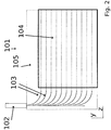
- Fig. 2 shows a top view of an alternative prior art optical device 101 for fanning-out light.
- a light source 102 is oriented at 90° with regard to a direction of extension of fan-out waveguides 103 over some active area 104.
- this still requires the bezel 105 around the active area 104 to be on the order of the bending radius at two sides of the display. In particular for mobile display applications, this is undesirable.
- Fig. 3 schematically shows an embodiment of an optical device 1 according to the present disclosure in a top view (y-z-plane) and Fig. 4 shows the same embodiment in a side view (x-z-plane).
- the optical device 1 comprises a primary fan-out waveguide 3, two secondary fan-out waveguides 4, and a fan-out coupler 5 for coupling a light beam between the primary fan-out waveguide 3 and the secondary fan-out waveguides 4.
- the fan-out coupler 5 is a berryer, such that light can be coupled to both secondary fan-out waveguides 4 with one coupler.
- the optical device 1 can equally only comprise one secondary fan-out waveguide 4 and the fan-out optical coupler 5 does not need to be a berryer.
- FIG. 4 is a side view in the plane, in which the primary fan-out waveguide 3 extends. However, it will be understood, that a side view of the secondary fan-out waveguides 4 will look similar, apart from that its extension in z-direction to the left will only reach to the fan-out optical coupler 5, as can be seen in Fig. 3 .
- the optical device 1 comprises one bus waveguide 6 associated with each of the secondary fan-out waveguides 4 and there is also provided for one bus waveguide 6 associated with the primary fan-out waveguide 3.
- the optical device 1 comprises a reflecting and coupling structure 7 connecting each secondary fan-out waveguide 4 and the respective bus waveguide 6.
- a similar reflecting and coupling structure also connects the primary fan-out waveguide 3 and the respective bus waveguide 6.
- a majority of the bus waveguide 6 extends substantially parallel to a section of the secondary fan-out waveguide 4, which section makes up more than 50 % of the length of the secondary fan-out waveguide 4.
- Each reflecting and coupling structure 7 is an interferometric structure 8 for coupling a light beam traveling in the secondary fan-out waveguide 4 into the respective associated bus waveguide 6 (or, in particular if the optical device 1 is used for sensing applications, coupling a light beam traveling in the bus waveguide 6 into the respective associated secondary fan-out waveguide 4) such that at least a fraction of the coupled light beam travels in the opposite direction after leaving the interferometric structure 8.
- the arrows next to the waveguides 4, 6 are an idealized illustration of the direction the light beams are traveling in the respective waveguide.
- the reflecting and coupling structure 7 comprises an optical coupler 9 (labeled “bus optical coupler") for coupling a light beam between the secondary fan-out waveguide 4 and the bus waveguide 6 on passing the bus optical coupler 9 in one direction, wherein substantially 50% of the light beam is coupled between the secondary fan-out waveguide 4 and the bus waveguide 6 on passing the bus optical coupler 9 in one direction.
- the length of the bus optical coupler 9, where the secondary fan-out waveguide 4 and the bus waveguide 6 are brought close to each other, can be less than 1 mm.
- the reflecting and coupling structure 7 comprises a bus reflective face 10 for at least partially reflecting a light beam in the bus waveguide 6 and a secondary fan-out reflective face 11 for at least partially reflecting a light beam in the secondary fan-out waveguide 4.
- the optical path length between the bus optical coupler 9 and the bus reflective face 10 is the same as the optical path length between the bus optical coupler 9 and the secondary fan-out reflective face 11.
- the reflecting and coupling structure 7 forms a balanced Michelson interferometric structure and/or a folded Mach-Zehnder interferometric structure, and substantially all light that enters the reflecting and coupling structure 7 in the secondary fan-out waveguide 4 leaves the reflecting and coupling structure 7 in the bus waveguide 6 in the reversed direction (due to constructive interference in the bus waveguide 6 on passing the bus optical coupler 9 for a second time and destructive interference in the secondary fan-out waveguide 4 on passing the bus optical coupler 9 for a second time).
- the primary fan-out waveguide 3, the secondary fan-out waveguide 4 and the bus waveguide 6 are provided in a transparent substrate 12. They are produced by femtosecond direct laser writing, which is a method to achieve 3D trajectories of the waveguides.
- the bus waveguide 6 and the secondary fan-out waveguide 4 or the primary fan-out waveguide, respectively are substantially extending in parallel along the z-direction and are spaced from one another in the x-direction and in the y-direction for most of their length. Thus, there is no problem with interference at their seeming point of intersection in the top view.
- the bus reflective face 10 and the secondary fan-out reflective face 11 are provided by a facet 13 of the transparent substrate 12.
- the optical device 1 comprises a plurality of pixel waveguides 14, which each receive a light beam from one of the bus waveguides 6 (or, in particular when using the optical device 1 for sensing applications, direct a light beam to one of the bus waveguides 6).
- the pixels waveguides 14 bend away from the respective bus waveguide 6 and bend towards a top surface 15 of the substrate 12, which comprises an active area that is to be illuminated by the optical device 1. If the optical device 1 is used as a backlight unit, each pixel waveguide 14 can for example illuminate one pixel or one color subpixel e.g. of a liquid crystal display (LCD).
- the pixel waveguides 14 can receive the light from the respective bus waveguide 6 via an optical coupler, e.g. by bringing the pixel waveguide 14 close to the respective bus waveguide 6.
- the optical device 1 comprises a light source 2, wherein a light beam emitted from the light source 2 is coupled into the primary fan-out waveguide 3, and is subsequently distributed via the secondary fan-out waveguides 4 and the bus waveguides 6 to the pixel waveguides 14.
- the entire extension of the substrate 12 in the y- and z-directions can be used for fanning-out, the active area can cover essentially the entire top surface 15 and there is no necessity for a bezel around the active area.
- Fig. 5 schematically shows another embodiment of an optical device 1 in a top view (y-z-plane) and Fig. 6 shows the same embodiment in a side view (x-z-plane).
- This embodiment is in most parts identical to the embodiment shown in Figs. 3 and 4 , however, some of the pixel waveguides 14 are placed differently.
- the area of the coupler can be part of the active area.
- Fig. 7 schematically shows an embodiment of an optical device 1 in a top view (y-z-plane) and Fig. 8 shows the same embodiment in a side view (x-z-plane).
- the optical device 1 comprises three light sources 2, which each couple light into a different primary fan-out waveguide 3.
- Each light source 2 can be configured to emit a different wavelength, e.g. red, blue and green light.
- the distribution of light beams from each of the primary fan-out waveguides 3 to the respective pixels waveguides 14 (not shown in Fig. 7 ) works in the same way as described in the context of Figs. 3 and 4 .
- the primary fan-out waveguide 3 and the secondary fan-out waveguides 4 of each light source 2 are on different levels of depth (x-axis) in the substrate 12 for most of their length (see Fig. 8 ), such that they can be interleaved.
- the primary fan-out waveguides 3 and the secondary fan-out waveguides 4 are brought to the same level only right before the reflecting and coupling structures 7.
- the fan-out of each light source 2, in particular of each color is independent from the other light sources 2, in particular the other colors. Therefore, also the reflecting and coupling structures 7 remain independent for different light sources 2 and can operate each on a single wavelength (and a different wavelength, depending on which light source they are connected to). In this way, low losses are achieved, while different colors are spread over the active area.
- Fig. 9 schematically illustrates an estimation model of optical losses due to the number of pixel waveguides.
- a typical pixel row consists of power carrying bus waveguides (i.e. the bus-line), and multiple couplers (i.e. the pixels), that remove/redirect part of the power carried by the bus-line towards the output facet of the substrate, in particular glass.
- the simplified model used for the following calculation is shown in Fig. 9 .
- power P 0 is coupled to the bus-line and propagates from left to right.
- the bus-line (waveguide from P 0 to P bus ) is coupled to a reference coupler and N couplers in series (i.e. pixels, in this case the straight diagonal parallel lines). After each coupler a portion of the power carried by the bus-line is removed.
- a reference waveguide coupled to the bus-line ends at the output facet on the right (P ref ). The steering of the reference waveguide towards the output facet is performed with a bending radius of 50 mm, high enough to neglect the bending losses coming from this region, and allowing a faithful estimation of the coupling C.
- the power at the output of the bus-line (P bus ) is a function of the number (N) of the couplers and their coupling coefficient C.
- N the number of the couplers and their coupling coefficient C.
- the reference waveguide is used to characterize the coupling coefficient of the couplers, and also verify the repeatability and stability of the fabrication process.
- 12 devices for each N were made, in order to have sufficient statistics (minimum statistical validity is achievable with 4 devices for each N).
- the couplers-waveguides were made with an interaction distance of 7.75 ⁇ m, interaction length of 0 ⁇ m, and bends with a radius of 10 mm. Bending radii related to pixel waveguides and couplers should be in the range of 10 mm to 50 mm to maintain low optical transmission losses lower than 0.2 dB.
- Fig. 10 schematically illustrates considerations concerning the reflecting and coupling structure, which should however not be considered limiting to the general concept of this disclosure.
- Integrated directional couplers whose output facet is metal coated have been fabricated and characterized, corresponding to Figs. 3 and 4 , but with all waveguides in the same x-plane for convenience of fabrication.
- the interaction region of the coupler is positioned 1 mm from the output surface, making it insensitive to the amount of polished material (300 ⁇ m to 600 ⁇ m), while proving its compactness.
- the interaction region of the coupler can have a distance from the output (coated and thus reflective) surface of less than 1 mm.
- polishing as post-processing the output surface a thickness of less than 600 ⁇ m is removed. This post-processing step can be avoided.
- a difference in the length of the two arms leads to an unbalanced optical power of the device, i.e. a reduction of the power transfer from the forward-direction waveguide to the backward-direction one.
- the reflective facet could be perpendicular with a precision of 0.1 degrees.
- a mechanical polishing process may easily produce a similar angle in the output facet.
- the arms of the coupler should be placed as close as possible. The distance of the arms of the coupler typically are set within a range of 15 ⁇ m to 100 ⁇ m. At the same time, the arms should not interact in order to preserve the behavior of the interferometer.
- the distance between two arms of the coupler is set to 15 ⁇ m. It is worth to notice that close arms allow to shrink the length of the overall device. Supposing to have a perfectly perpendicular facet, the distance between the arms may increase up to e.g. 100 ⁇ m.
- This optical circuit has been built in a 25 times 25 times 0.5 mm 3 alumino-borosilicate glass (Eagle XG, Corning), through a technique known as "femtosecond-laser direct writing". This process exploits the nonlinear interaction between focused ultrashort optical pulses and a dielectric substrate, to produce permanent modifications within the material.
- this approach allows the fabrication of single-mode waveguides featuring a core of circa 3 ⁇ m and a refractive index contrast of about 5 ⁇ 10 ⁇ -3.
- the wavelength adopted for the measurements is 638 nm, at which these waveguides exhibit a mode field diameter of 4.2 ⁇ m, propagation losses of 0.1 dB/cm and bending losses of 0.45 dB/cm at a bending radius of 10 mm.
- the characterization has been divided in two parts: first, the operation of the directional coupler without coating is evaluated. In this phase, light is coupled through a fiber in one mode on the input facet and the power distribution among the two output-modes is measured with a power-meter. The splitting ratio is then retrieved.
- the relative power transferred from the input-mode to the reflected coupled one was 92.64%, with a standard deviation of 0.91% among 10 identical devices.
- This working principle is also proved to be independent on the arms distance and length.
- the complete power transfer is hindered both by the unbalancement of the directional coupler (50.24% splitting ratio with a standard deviation of 0.96%) and, more strongly, by the tilt of the output facet.
- the latter randomly produced during the polishing process, leads to a difference in the path-length of the two arms and hence imperfect device performance, which can be easily avoided by using more precise - currently available - polishing/cutting techniques, such as laser cutting.
- Fig. 11 shows a side view of another embodiment of the optical device 1 according to the present disclosure.
- This embodiment comprises a multi-layer layout.
- the optical device 1 functions between the light source 2 up to the bus waveguides 6 and the pixels waveguides 14 (not shown in Fig. 11 ) leading to the top surface 15 in substantially the same way as described in the context of the embodiment shown in Fig. 3 and 4 (just with the x-dimension shown reversed).
- another reflecting and coupling structure 7a in particular another interferometric structure, with another bus optical coupler 9a and a reflection at another facet 13a.
- the other reflecting and coupling structure 7a couples light between the bus waveguide 6 and another bus waveguide or detection waveguide 16.
- Fig. 11 shows this for the bus waveguide 6 connected to the primary fan-out waveguide 3.
- this may also (or instead) be provided for at least one bus waveguide 6 connected to a respective secondary fan-out waveguide 4.
- the direction of light travelling in the respective waveguides is schematically illustrated by arrows.
- a crossing of the detection waveguide 16 with the primary fan-out waveguide 3 or, respectively, one of the secondary fan-out waveguides 4 is avoided by bypassing it in the y-dimension at around the spot 17.
- the detection waveguide 16 leads to a respective detector 18, in particular a photodiode, which makes it possible to analyze the light arriving there.
- this embodiment is particularly useful for touch sensing applications.
Landscapes
- Physics & Mathematics (AREA)
- General Physics & Mathematics (AREA)
- Optics & Photonics (AREA)
- Engineering & Computer Science (AREA)
- Microelectronics & Electronic Packaging (AREA)
- Optical Couplings Of Light Guides (AREA)
- Optical Integrated Circuits (AREA)
Priority Applications (5)
| Application Number | Priority Date | Filing Date | Title |
|---|---|---|---|
| EP20425020.3A EP3926233A1 (fr) | 2020-06-19 | 2020-06-19 | Dispositif optique |
| PCT/EP2021/066616 WO2021255241A1 (fr) | 2020-06-19 | 2021-06-18 | Dispositif optique |
| KR1020237001471A KR20230028381A (ko) | 2020-06-19 | 2021-06-18 | 광학 장치 |
| US18/000,721 US20230213696A1 (en) | 2020-06-19 | 2021-06-18 | Optical device |
| CN202180038108.8A CN115769022A (zh) | 2020-06-19 | 2021-06-18 | 光学装置 |
Applications Claiming Priority (1)
| Application Number | Priority Date | Filing Date | Title |
|---|---|---|---|
| EP20425020.3A EP3926233A1 (fr) | 2020-06-19 | 2020-06-19 | Dispositif optique |
Publications (1)
| Publication Number | Publication Date |
|---|---|
| EP3926233A1 true EP3926233A1 (fr) | 2021-12-22 |
Family
ID=71670203
Family Applications (1)
| Application Number | Title | Priority Date | Filing Date |
|---|---|---|---|
| EP20425020.3A Pending EP3926233A1 (fr) | 2020-06-19 | 2020-06-19 | Dispositif optique |
Country Status (5)
| Country | Link |
|---|---|
| US (1) | US20230213696A1 (fr) |
| EP (1) | EP3926233A1 (fr) |
| KR (1) | KR20230028381A (fr) |
| CN (1) | CN115769022A (fr) |
| WO (1) | WO2021255241A1 (fr) |
Citations (5)
| Publication number | Priority date | Publication date | Assignee | Title |
|---|---|---|---|---|
| US6226426B1 (en) * | 1997-03-20 | 2001-05-01 | Commissariat A L'energie Atomique | Device for demultiplexing light paths contained in an optical spectrum |
| WO2007046100A2 (fr) | 2005-10-18 | 2007-04-26 | Oms Displays Ltd. | Dispositif et procede de redimensionnement optique et de retroeclairage |
| US20080107380A1 (en) * | 2001-07-03 | 2008-05-08 | Brown University Research Foundation | Method and apparatus for processing optical signals with supergratings |
| WO2016039166A1 (fr) * | 2014-09-12 | 2016-03-17 | 日東電工株式会社 | Capteur de position |
| EP3599541A1 (fr) * | 2018-07-26 | 2020-01-29 | University of Vienna | Guide d'ondes optique émetteur de lumière et écran tactile |
Family Cites Families (13)
| Publication number | Priority date | Publication date | Assignee | Title |
|---|---|---|---|---|
| US4107518A (en) * | 1977-01-26 | 1978-08-15 | Sperry Rand Corporation | Optical repeater |
| US4246475A (en) * | 1978-05-03 | 1981-01-20 | The United States Of America As Represented By The Secretary Of The Navy | Fail-safe optical repeater-amplifier assembly for fiber optic systems |
| US4234969A (en) * | 1978-09-05 | 1980-11-18 | Ncr Corporation | Bidirectional optical coupler for a data processing system |
| US4317614A (en) * | 1980-02-20 | 1982-03-02 | General Dynamics, Pomona Division | Fiber optic bus manifold |
| US6839478B2 (en) * | 2001-05-01 | 2005-01-04 | Terraop Ltd. | Optical switching system based on hollow waveguides |
| US20040047537A1 (en) * | 2002-09-06 | 2004-03-11 | Boord Warren Timothy | Fan-out circuit with integrated active and passive components |
| US20060215954A1 (en) * | 2004-03-22 | 2006-09-28 | Jenkins Richard M | Optical routing device comprising hollow waveguides and mems reflective elements |
| JP2006011295A (ja) * | 2004-06-29 | 2006-01-12 | Fuji Photo Film Co Ltd | 導光体の製造方法 |
| US20060120725A1 (en) * | 2004-12-03 | 2006-06-08 | Braun Steve W | Optical interface devices for optical communications |
| US7499615B2 (en) * | 2007-08-01 | 2009-03-03 | Hewlett-Packard Development Company, L.P. | System and methods for routing optical signals |
| US20160085027A1 (en) * | 2013-07-30 | 2016-03-24 | The Boeing Company | Tapered optical mixing rods |
| CN107615121B (zh) * | 2015-03-16 | 2021-04-16 | 加利福尼亚太平洋生物科学股份有限公司 | 用于自由空间光耦合的集成装置及系统 |
| TWI706177B (zh) * | 2019-09-12 | 2020-10-01 | 源傑科技股份有限公司 | 光信號產生裝置 |
-
2020
- 2020-06-19 EP EP20425020.3A patent/EP3926233A1/fr active Pending
-
2021
- 2021-06-18 CN CN202180038108.8A patent/CN115769022A/zh active Pending
- 2021-06-18 US US18/000,721 patent/US20230213696A1/en active Pending
- 2021-06-18 WO PCT/EP2021/066616 patent/WO2021255241A1/fr active Application Filing
- 2021-06-18 KR KR1020237001471A patent/KR20230028381A/ko active Search and Examination
Patent Citations (5)
| Publication number | Priority date | Publication date | Assignee | Title |
|---|---|---|---|---|
| US6226426B1 (en) * | 1997-03-20 | 2001-05-01 | Commissariat A L'energie Atomique | Device for demultiplexing light paths contained in an optical spectrum |
| US20080107380A1 (en) * | 2001-07-03 | 2008-05-08 | Brown University Research Foundation | Method and apparatus for processing optical signals with supergratings |
| WO2007046100A2 (fr) | 2005-10-18 | 2007-04-26 | Oms Displays Ltd. | Dispositif et procede de redimensionnement optique et de retroeclairage |
| WO2016039166A1 (fr) * | 2014-09-12 | 2016-03-17 | 日東電工株式会社 | Capteur de position |
| EP3599541A1 (fr) * | 2018-07-26 | 2020-01-29 | University of Vienna | Guide d'ondes optique émetteur de lumière et écran tactile |
Non-Patent Citations (3)
| Title |
|---|
| ROSS: "Ion-exchanged glass waveguide sensors", GLASS INTEGRATED OPTICS AND OPTICAL FIBER DEVICES: A CRITICAL ' REVIEW, 25 July 1994 (1994-07-25), pages 102750C, XP060094284, DOI: 10.1117/12.179753 |
| TRAVIS ET AL., OPT. EXPRESS, vol. 17, 2009, pages 19714 - 19719 |
| VAN ACOLEYEN ET AL.: "Optical Retroreflective Marker Fabricated on Silicon-On-Insulator", IEEE PHOTONICS JOURNAL, vol. 3, no. 5, October 2011 (2011-10-01), pages 789 - 798, XP011485122, DOI: 10.1109/JPHOT.2011.2164783 |
Also Published As
| Publication number | Publication date |
|---|---|
| US20230213696A1 (en) | 2023-07-06 |
| WO2021255241A1 (fr) | 2021-12-23 |
| KR20230028381A (ko) | 2023-02-28 |
| CN115769022A (zh) | 2023-03-07 |
Similar Documents
| Publication | Publication Date | Title |
|---|---|---|
| US8594503B2 (en) | Method and system for multiplexer waveguide coupling | |
| US7272279B2 (en) | Waveguide type optical branching device | |
| US5745619A (en) | Low-loss optical power splitter for high-definition waveguides | |
| US20160246009A1 (en) | Photonic Chip Surface Grating Coupler (SGC)-Based Optical Splitter and Optical Combiner | |
| JP3543121B2 (ja) | 光導波路接続構造 | |
| US20050036737A1 (en) | Waveguide lens with multimode interference | |
| EP1662284B1 (fr) | Dispositif optique, procede de fabrication de dispositif optique et dispositif optique integre | |
| JP2003050330A (ja) | 光学デバイス | |
| US5764825A (en) | Optical wavelength division multiplexer device | |
| JP6300437B2 (ja) | 光導波路素子 | |
| US10564355B2 (en) | Optical waveguide element | |
| CN116508272A (zh) | 用于光纤通信的基于超表面的光学信号操控装置 | |
| US8498503B2 (en) | Integrated optical coupler | |
| US10048441B1 (en) | Variable optical splitter system | |
| CN110312918B (zh) | 基于高分辨率集成光学器件的光谱仪 | |
| EP3926233A1 (fr) | Dispositif optique | |
| US11860411B2 (en) | Super-compact arrayed waveguide grating (AWG) wavelength division multiplexer based on sub-wavelength grating | |
| US20240126014A1 (en) | Compact dual polarization couplers for multi-core optical fibers | |
| JP2961057B2 (ja) | 光分岐ディバイス | |
| Aalto et al. | Development of silicon-on-insulator waveguide technology | |
| JP2021012334A (ja) | 光変調器および光学測定装置 | |
| CN112230336B (zh) | 一种支持片上多模式的任意比例分光器 | |
| Li et al. | Experimental demonstration and simulation of lossless metal-free integrated elliptical reflectors for waveguide turnings and crossings | |
| JP5463832B2 (ja) | 光変調器 | |
| JP7087547B2 (ja) | 光センサ装置 |
Legal Events
| Date | Code | Title | Description |
|---|---|---|---|
| PUAI | Public reference made under article 153(3) epc to a published international application that has entered the european phase |
Free format text: ORIGINAL CODE: 0009012 |
|
| STAA | Information on the status of an ep patent application or granted ep patent |
Free format text: STATUS: THE APPLICATION HAS BEEN PUBLISHED |
|
| AK | Designated contracting states |
Kind code of ref document: A1 Designated state(s): AL AT BE BG CH CY CZ DE DK EE ES FI FR GB GR HR HU IE IS IT LI LT LU LV MC MK MT NL NO PL PT RO RS SE SI SK SM TR |
|
| B565 | Issuance of search results under rule 164(2) epc |
Effective date: 20201123 |
|
| STAA | Information on the status of an ep patent application or granted ep patent |
Free format text: STATUS: REQUEST FOR EXAMINATION WAS MADE |
|
| RBV | Designated contracting states (corrected) |
Designated state(s): AL AT BE BG CH CY CZ DE DK EE ES FI FR GB GR HR HU IE IS IT LI LT LU LV MC MK MT NL NO PL PT RO RS SE SI SK SM TR |
|
| 17P | Request for examination filed |
Effective date: 20220622 |
|
| RAP3 | Party data changed (applicant data changed or rights of an application transferred) |
Owner name: CONSIGLIO NAZIONALE DELLE RICERCHE Owner name: VITREALAB GMBH |
|
| RIN1 | Information on inventor provided before grant (corrected) |
Inventor name: OSELLAME, ROBERTO Inventor name: PITSIOS, IOANNIS Inventor name: PELLEGATTA, FRANCESCO Inventor name: GREGANTI, CHIARA Inventor name: ZEUNER, JONAS |
|
| GRAP | Despatch of communication of intention to grant a patent |
Free format text: ORIGINAL CODE: EPIDOSNIGR1 |
|
| STAA | Information on the status of an ep patent application or granted ep patent |
Free format text: STATUS: GRANT OF PATENT IS INTENDED |
|
| RIC1 | Information provided on ipc code assigned before grant |
Ipc: G06F 3/042 20060101ALN20240126BHEP Ipc: G02B 6/125 20060101ALI20240126BHEP Ipc: G02B 6/122 20060101ALI20240126BHEP Ipc: F21V 8/00 20060101AFI20240126BHEP |
|
| INTG | Intention to grant announced |
Effective date: 20240212 |