EP3926219B1 - Geteilte v-ring-dichtungsanordnung - Google Patents
Geteilte v-ring-dichtungsanordnung Download PDFInfo
- Publication number
- EP3926219B1 EP3926219B1 EP21178915.1A EP21178915A EP3926219B1 EP 3926219 B1 EP3926219 B1 EP 3926219B1 EP 21178915 A EP21178915 A EP 21178915A EP 3926219 B1 EP3926219 B1 EP 3926219B1
- Authority
- EP
- European Patent Office
- Prior art keywords
- seal body
- coupler
- seal
- teeth
- members
- Prior art date
- Legal status (The legal status is an assumption and is not a legal conclusion. Google has not performed a legal analysis and makes no representation as to the accuracy of the status listed.)
- Active
Links
Images




Classifications
-
- F—MECHANICAL ENGINEERING; LIGHTING; HEATING; WEAPONS; BLASTING
- F16—ENGINEERING ELEMENTS AND UNITS; GENERAL MEASURES FOR PRODUCING AND MAINTAINING EFFECTIVE FUNCTIONING OF MACHINES OR INSTALLATIONS; THERMAL INSULATION IN GENERAL
- F16J—PISTONS; CYLINDERS; SEALINGS
- F16J15/00—Sealings
- F16J15/02—Sealings between relatively-stationary surfaces
- F16J15/06—Sealings between relatively-stationary surfaces with solid packing compressed between sealing surfaces
- F16J15/067—Split packings
-
- F—MECHANICAL ENGINEERING; LIGHTING; HEATING; WEAPONS; BLASTING
- F16—ENGINEERING ELEMENTS AND UNITS; GENERAL MEASURES FOR PRODUCING AND MAINTAINING EFFECTIVE FUNCTIONING OF MACHINES OR INSTALLATIONS; THERMAL INSULATION IN GENERAL
- F16J—PISTONS; CYLINDERS; SEALINGS
- F16J15/00—Sealings
- F16J15/16—Sealings between relatively-moving surfaces
- F16J15/34—Sealings between relatively-moving surfaces with slip-ring pressed against a more or less radial face on one member
- F16J15/3436—Pressing means
- F16J15/3456—Pressing means without external means for pressing the ring against the face, e.g. slip-ring with a resilient lip
-
- F—MECHANICAL ENGINEERING; LIGHTING; HEATING; WEAPONS; BLASTING
- F16—ENGINEERING ELEMENTS AND UNITS; GENERAL MEASURES FOR PRODUCING AND MAINTAINING EFFECTIVE FUNCTIONING OF MACHINES OR INSTALLATIONS; THERMAL INSULATION IN GENERAL
- F16J—PISTONS; CYLINDERS; SEALINGS
- F16J15/00—Sealings
- F16J15/16—Sealings between relatively-moving surfaces
- F16J15/32—Sealings between relatively-moving surfaces with elastic sealings, e.g. O-rings
- F16J15/3204—Sealings between relatively-moving surfaces with elastic sealings, e.g. O-rings with at least one lip
-
- F—MECHANICAL ENGINEERING; LIGHTING; HEATING; WEAPONS; BLASTING
- F16—ENGINEERING ELEMENTS AND UNITS; GENERAL MEASURES FOR PRODUCING AND MAINTAINING EFFECTIVE FUNCTIONING OF MACHINES OR INSTALLATIONS; THERMAL INSULATION IN GENERAL
- F16J—PISTONS; CYLINDERS; SEALINGS
- F16J15/00—Sealings
- F16J15/16—Sealings between relatively-moving surfaces
- F16J15/32—Sealings between relatively-moving surfaces with elastic sealings, e.g. O-rings
- F16J15/3268—Mounting of sealing rings
-
- F—MECHANICAL ENGINEERING; LIGHTING; HEATING; WEAPONS; BLASTING
- F16—ENGINEERING ELEMENTS AND UNITS; GENERAL MEASURES FOR PRODUCING AND MAINTAINING EFFECTIVE FUNCTIONING OF MACHINES OR INSTALLATIONS; THERMAL INSULATION IN GENERAL
- F16J—PISTONS; CYLINDERS; SEALINGS
- F16J15/00—Sealings
- F16J15/16—Sealings between relatively-moving surfaces
- F16J15/32—Sealings between relatively-moving surfaces with elastic sealings, e.g. O-rings
- F16J15/3268—Mounting of sealing rings
- F16J15/3272—Mounting of sealing rings the rings having a break or opening, e.g. to enable mounting on a shaft otherwise than from a shaft end
-
- F—MECHANICAL ENGINEERING; LIGHTING; HEATING; WEAPONS; BLASTING
- F16—ENGINEERING ELEMENTS AND UNITS; GENERAL MEASURES FOR PRODUCING AND MAINTAINING EFFECTIVE FUNCTIONING OF MACHINES OR INSTALLATIONS; THERMAL INSULATION IN GENERAL
- F16J—PISTONS; CYLINDERS; SEALINGS
- F16J15/00—Sealings
- F16J15/16—Sealings between relatively-moving surfaces
- F16J15/32—Sealings between relatively-moving surfaces with elastic sealings, e.g. O-rings
- F16J15/3284—Sealings between relatively-moving surfaces with elastic sealings, e.g. O-rings characterised by their structure; Selection of materials
-
- F—MECHANICAL ENGINEERING; LIGHTING; HEATING; WEAPONS; BLASTING
- F16—ENGINEERING ELEMENTS AND UNITS; GENERAL MEASURES FOR PRODUCING AND MAINTAINING EFFECTIVE FUNCTIONING OF MACHINES OR INSTALLATIONS; THERMAL INSULATION IN GENERAL
- F16J—PISTONS; CYLINDERS; SEALINGS
- F16J15/00—Sealings
- F16J15/16—Sealings between relatively-moving surfaces
- F16J15/34—Sealings between relatively-moving surfaces with slip-ring pressed against a more or less radial face on one member
- F16J15/3464—Mounting of the seal
- F16J15/3488—Split-rings
Definitions
- the present invention relates to seals, and more particularly to seals for sealing against a radial surface.
- Seals for sealing against a radial surface or "axial face” are known and typically include an annular body disposed about a first member and having a lip for sealing against an axial face/ radial surface of a second member disposed about or adjacent to the first member.
- One such type of seal is commonly referred to as a "V-ring” seal which includes an annular main body and an axially-extending lip separated from the main body by an annular groove, such that the seal has generally V-shaped cross-sections.
- Such seals are usually fabricated in numerous different standard sizes that are each made to fit about a specific size of a first member, such as a shaft.
- German Patent No. DE 10 2013 203266 A1 teaches a sealing element cut to length and arranged circularly about a shaft such that two ends abut, and then has a clamping lug attached to each end. Two gripping elements are each hooked to a separate one of the lugs and pull the lugs toward each other by means of a pulling tool, then a clamping element is connected to each lug to hold the ends of the sealing element together.
- 9,132,539 discloses a method of forming a V-ring seal which includes cutting an elastomeric member with a groove to a desired length that fits about a shaft, wrapping the cut member about the shaft so that two ends abut, and then positioning a biasing member, for example a garter spring, within the groove to retain the sealing member about the shaft.
- a biasing member for example a garter spring
- the present invention is a seal assembly for sealing between a first member and a second member, the first member having an outer circumferential surface and the second member being disposed about or adjacent to an end of the first member and having a radial surface.
- the seal assembly comprises an annular seal body disposeable about the first member and having a centerline, an axially-extending sealing lip engageable with the radial surface of the second member, two circumferential ends and an outer circumferential surface.
- a plurality of teeth extend outwardly from the outer circumferential surface and are spaced circumferentially about the centerline.
- a first coupler member has a plurality of spaced apart teeth, each tooth of the first coupler member being disposed between a separate pair of adjacent teeth of the seal body so as to define a first attachment interface adjacent to the first circumferential end of the seal body.
- the first coupler member is attached to the annular body at the first attachment interface.
- a second coupler member has a plurality of spaced apart teeth, each tooth of the second coupler member being disposed between a separate pair of adjacent teeth of the seal body so as to define a second attachment interface adjacent to the second circumferential end of the seal body.
- the second coupler member is attached to the annular body at the second attachment interface.
- the first and second coupler members are connected so as to couple the first and second ends of the seal body and to retain the seal assembly about the first member outer circumferential surface.
- the present invention is a method of forming a seal assembly for sealing between a first member and a second member disposed about or adjacent to an end of the first member.
- the method comprises the steps of: molding an integral annular seal body having a centerline, an inside diameter and an outer circumferential surface; providing first and second coupler members; calculating a reduction of a circumferential length of the integral seal body to reduce the inside diameter of the seal body to a desired value of about an outside diameter of the first member; removing an arcuate portion of the calculated length from the seal body so as to form first and second circumferential ends and reduce the body inside diameter to the desired value when the first and second circumferential ends are connected; attaching the first and second coupler members to the outer surface of the seal body; and connecting the first and second coupler members such that the body first and second circumferential ends are at least generally adjacent and the seal body is retained in an annular configuration with an inside diameter of the desired value.
- the present invention is again a method of forming a seal assembly, comprising the steps of: molding an annular seal body having an inside diameter, an outer circumferential surface and a plurality of teeth extending outwardly from outer surface; providing first and second coupler members each having opposing ends and a plurality of teeth spaced between the ends; calculating a reduction of a circumferential length of the molded body to reduce the inside diameter of the seal body to a desired value; juxtaposing the first coupler member against the seal body outer surface such that each one of the teeth of the first coupler member is disposed between a separate pair of adjacent teeth of the seal body so as to form a first attachment interface and attaching the juxtaposed first coupler member to the seal body; juxtaposing the second coupler member against the seal body outer surface such that each one of the teeth of the first coupler member is disposed between a separate pair of adjacent teeth of the seal body so as to form a second attachment interface and attaching the juxtaposed second coupler member to the seal body, the second attachment interface having
- the present invention is again a seal assembly for sealing between a first member and a second member, the first member having an outer circumferential surface and the second member being disposed about or adjacent to an end of the first member and having a radial surface.
- the seal assembly comprises an annular seal body disposeable about the first member and having a centerline, an axially-extending sealing lip engageable with the radial surface of the second member, two circumferential ends, and an outer circumferential surface. At least one of a plurality of projections extend outwardly from the outer circumferential surface and spaced circumferentially about the centerline and a plurality of openings are spaced circumferentially about the centerline.
- a first coupler member has at least one of a plurality of spaced apart projections each disposed within a separate one of the openings of the seal body and a plurality of spaced apart openings each receiving a separate projection of the seal body so as to define a first attachment interface adjacent to the first circumferential end of the seal body, the first coupler member being attached to the seal body at the first attachment interface.
- a second coupler member has at least one of a plurality of spaced apart projections each disposed within a separate one of the openings of the seal body and a plurality of spaced apart openings each receiving a separate projection of the seal body so as to define a second attachment interface adjacent to the second circumferential end of the seal body, the second coupler member being attached to the seal body at the second attachment interface.
- the first and second coupler members are connected so as to couple the first and second circumferential ends of the seal body and retain the seal assembly about the first member outer circumferential surface.
- a further aspect of the invention describes a method of forming a seal assembly comprising the steps of:
- a further aspect of the invention describes a seal assembly for sealing between a first member and a second member, the first member having an outer circumferential surface and the second member being disposed about or adjacent to an end of the first member and having a radial surface, the seal assembly comprising:
- a seal assembly 10 for sealing between a first member 1 having a central axis Ac and an outer circumferential surface 1a and a second member 2 disposed about, or adjacent to an end of, the first member 1 and having a radial surface 2a, one of the members 1, 2 being rotatable or pivotable about the axis Ac.
- the first member 1 may be a bearing inner ring and the second member 2 may be an outer housing, the first member 1 may be a shaft and the second member 2 may be a seal case, etc.
- the seal assembly 10 basically comprises an annular seal body 12 with two circumferential ends 12a, 12b and first and second coupler members 14, 16, respectively, attached to the seal body 12 and connectable to couple the body ends 12a, 12b.
- the seal body 12 and the first and second coupler members 14, 16 are each formed of an elastomeric material, most preferably natural or synthetic rubber, but may be formed of any other appropriate material(s).
- the seal body 12 is disposeable about, and coupleable with, the first member 1 and has a centerline C L and an axially-extending sealing lip 18 sealingly engageable with the radial surface 2a of the second member 2.
- the seal body 12 further has an inner circumferential surface 13A sealingly engageable with the first member 1, an opposing outer circumferential surface 13B and a plurality of projections 19 and/or openings 21 spaced circumferentially about the centerline C L .
- the body 12 has both a plurality of axial teeth 20 extending outwardly from the outer circumferential surface 13B and providing the projections 19, and a plurality of axial channels 26 each defined between a separate pair of adjacent teeth 20 and providing the openings 21.
- first and second coupler members 14, 16 each have at least one of complementary projections 19 or/and complementary openings 21 designed to engage with the specific structure of the seal body 12. That is, the two coupler members 14, 16 each include at least projections 19 disposeable within openings 21 of the seal body 12 or openings 21 for receiving projections 19 of the seal body 12.
- the first coupler member 14 has a plurality of spaced apart teeth 22 providing projections 19 and a plurality of channels 35 defined between the teeth 22 and providing openings 21.
- Each tooth 22 of the first coupler member 14 is disposed in a channel 26 between a separate pair of adjacent teeth 20 of the seal body 12 so as to define a first attachment interface AI 1 adjacent to the first circumferential end 12a of the seal body 12.
- the first coupler member 14 is attached to the annular body 12 at the first attachment interface AI 1 , preferably by bonding through means of an appropriate adhesive, etc., but may be attached by fasteners or any other appropriate means.
- the second coupler member 16 also has a plurality of spaced apart teeth 24 providing projections 19 and a plurality of channels 37 defined between the teeth 24 and providing openings 21.
- Each tooth 24 of the second coupler member 16 is disposed between a separate pair of adjacent teeth 20 of the seal body 12 so as to define a second attachment interface AI 2 adjacent to the second circumferential end 12b of the seal body 12.
- the second coupler member 16 is attached to the annular body 12 at the second attachment interface AI 2 , preferably by adhesive bonding or another appropriate means (fasteners, thermal bonding, etc.).
- first and second coupler members 14, 16 are connected together so as to couple the first and second ends 12a, 12b of the seal body 12 and to retain the seal assembly 10 about the outer circumferential surface 1a of the first member 1.
- the first and second circumferential ends 12a, 12b of the seal body 12 are abutting when the coupler members 14, 16 are connected.
- the seal body ends 12a, 12b may alternatively be spaced apart by an intermediary member (e.g., an elastomeric spacer, none shown) particularly if the seal body inside diameter ID 1 is unintentionally formed substantially less than the outside diameter ODi of the first member 1, as discussed below.
- the seal body 12 is preferably formed by "cutting down" an integral seal body 11 to a desired size for a particular application, i.e., to fit the outside diameter ODi of the first member 1. That is, the seal body 12 has a first inside diameter ID 1 of a desired value and is formed by cutting an arcuate portion 11a from an integral annular body 11 having a second, greater inside diameter ID 2 , as shown in Fig. 10A .
- each one of the first and second coupler members 14, 16 is preferably formed from a separate generally rectangular block 30, 32, respectively, having an elongated surface 31A, 33A, with the teeth 22, 24 of each one of the first and second coupler members 14, 16 extending from the block elongated surface 31A, 33A.
- each block 30, 32 is bended such that the elongated surface 31A, 33A is juxtaposable against the curved seal body outer circumferential surface 13B to form the attachment interfaces AI 1 , AI 2 as described above and in further detail below.
- the coupler members 14, 16 are attached to the molded seal body 11 and then the arcuate portion 11a is removed (e.g., by cutting), but may be attached to the seal body 12 after removing the arcuate portion 11a. Having described the basic components and structure above, these and other elements of the seal assembly 10 are described in detail below.
- the seal body 12 preferably includes a main body section 40 having generally rectangular axial cross-sections and providing the seal body inner and outer circumferential surfaces 13A, 13B.
- the seal main body section 40 has two opposing axial ends 40a, 40b, the sealing lip 18 extending axially and radially outwardly from the one axial end 40a and each of the plurality of teeth 20 extending axially between the two axial ends 40a, 40b.
- sealing lip 18 is generally frustoconical and has an inner radial end 18a integrally formed with the main body section 40 and a free, outer radial end 18b engageable with the radial surface 2a of the second member 2, an annular groove 42 being defined between the sealing lip 18 and the main body section 40.
- each one of the teeth 20 of the seal body 12 preferably has a flat outer end surface 20a and a pair of curved concave side surfaces 23A, 23B, such that a generally semicircular axial channel 26 is defined between each pair of adjacent teeth 20, for reasons discussed above and in further detail below.
- each one of the plurality of teeth 20 of the seal body 12 are preferably spaced from each adjacent tooth 20 by a spacing distance Ds, which corresponds to the width of each coupler member tooth 22 or 24, as discussed below.
- the main body section 40 of the seal body 12 preferably includes a radial flange 44 extending outwardly from the outer circumferential surface 13B adjacent to the body second axial end 40b. As such, the flange 44 encloses one end of each channel 26, which assists in retaining each coupler 14, 16 during bonding at each one of the first and second attachment interfaces AI 1 , AI 2 .
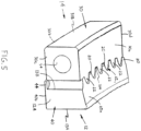
- each elongated block 30, 32 of the first and second coupler members 14, 16, respectively is preferably bended or arcuate (although relatively shallowly) when attached to the seal body 12 and positioned such that the elongated surfaces 31A, 31B are inner circumferential surfaces, as best shown in Fig. 5 .
- each block 30, 32 further has an opposing outer circumferential surface 31B, 33B, a first axial end 30a, 32a, an opposing second axial end 30b, 32b, an inner circumferential end 30c, 32c and an opposing outer circumferential end 30d, 32d.
- inner circumferential ends 30c, 32c are intended to indicate that these ends 30c, 32c are abutting (or at least adjacent to each other) when the coupler members 14, 16 are connected, while the “outer” ends 30d, 32d are on the external ends of the connected coupler members 14, 16.
- each tooth 22, 24 of each one of the first and second coupler members 14, 16 project from the inner circumferential surface 31A, 33A of each coupler member block 30, 32 so as to extend between the block first and second axial ends 30a, 30b and 32a, 32b, respectively.
- the teeth 22, 24 are spaced apart between the block inner and outer circumferential ends 30c, 30d and 32c, 32d, respectively, such that axial channels 35, 37 are defined between each pair of adjacent teeth 20, 24, respectively.
- each tooth 22, 24 of each one of the first and second coupler members 14, 16 has a thickness T T ( Fig. 9 ) about equal to or lesser than the spacing distance Ds ( Fig. 6 ) of the teeth 20 of the seal body 12.
- each one of the coupler member teeth 22, 24 has a generally semicircular cross-sectional shape and is disposed within a separate one of the axial channels 26 of the seal body 12 and against the curved side surfaces 23A and 23B of a pair of adjacent teeth 20 of the seal body 12, as best shown in Fig. 5 .
- each bonded attachment interface AI 1 , AI 2 are able to withstand substantially greater circumferential stresses (e.g., hoop shear) in comparison with a "flat" attachment interface.
- the greater strength of the bonded interfaces AI 1 , AI 2 is due both to the substantially greater bonded surface area for a given circumferential length of each interface AI 1 , AI 2 and the capability of the interlocking teeth 20/22 and 20/24 to resist circumferential forces as opposed to an adhesive layer alone.
- the elongated block 30, 32 of each one of the first and second coupler members 14, 16 further includes a bore 34, 36, respectively, extending between the two circumferential ends 30c, 30d and 32c, 32d of the respective block 30, 32.
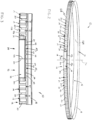
- the seal assembly 10 preferably further comprises a fastener 38 extending through the bore 34, 36 of each one of the coupler member blocks 30, 32 and configured to connect the first and second coupler members 14, 16, as shown in Figs. 2, 3 and 10D .
- the fastener 38 is preferably a conventional bolt having a head 38a abutting against the outer circumferential end 30d or 32d of one block 30, 32 and a threaded portion 38b extending outwardly from the other circumferential end 32d, 30d.
- a nut 39 is threadably engaged with the bolt threaded portion 39a such that the coupler members 14, 16, and thus the seal body ends 12a, 12b, are releasably coupled. Due to the relatively shallow curvature of the attached coupler blocks 30, 32 and the elasticity of the preferred elastomeric materials of the coupler members 14, 16, the fastener 38 is capable of insertion through the aligned bores 34, 36 even though the bores 34, 36 have a degree of curvature.
- the fastener 38 is removable from the first and second coupler members 14, 16 in order to disassemble the seal assembly 10 from about the first member 1.
- the seal assembly 10 is both installable about the first member 1 when the member 1 is assembled into a machine or other final application, which may prevent installation of an integral seal body, and readily removable from the member 1 in the assembled state.
- the coupler members 14, 16 may be connected together, removably or permanently, by any other appropriate means, such as for example, another type of fastener, an interlocking projection and recess of the blocks 30, 32, a rivet through the blocks 30, 32, etc.
- the present seal assembly 10 is preferably formed in the following manner.
- an integral annular seal body 11 is molded having an inside diameter of the second, greater value ID 2 and the plurality of teeth 20 spaced about the entire circumference of the body 11, as shown in Fig. 10A .
- the coupler members 14, 16 may be attached at any desired relative location about the circumference of the body 11.
- the teeth 20 may be provided around only a portion of the body perimeter or in two or more discrete sections of the perimeter (no alternatives shown).
- the coupler members 14, 16 are also formed or provided as the straight rectangular blocks 30, 32 with the coupler member teeth 22, 24, respectively, as best shown in Figs. 8 and 9 and described above.
- a reduction of the circumferential length or perimeter of the integral seal body 11 is calculated which will reduce the inside diameter of the seal body 12 to a desired value of about an outside diameter ODi ( Fig. 1 ) of the first member 1.
- an arcuate portion 11a of the calculated length Lc is removed from the seal body 12 so as to form the seal body first and second circumferential ends 12a, 12b and reduce the body inside diameter to the desired value ID 1 when the body first and second ends 12a, 12b are thereafter connected.
- the first and second coupler members 14, 16 are attached to the integral seal body 11 prior to removal of the arcuate portion 11a, as best shown in Fig. 10B , most preferably by attaching the first coupler member 14 to the integral seal body 11 and then attaching the second coupler member 16 to the seal body 11 at a point spaced from the first coupler member 14.
- the second coupler member 16 is located such that the inner circumferential end 32c of the second coupler member 16 is spaced from the inner circumferential end 30c of the first coupler member 14 by a distance D R of about the calculated reduction in circumferential length Lc of the body 11, as indicated in Fig. 10B .
- each coupler member 14, 16 is juxtaposed with the outer surface 13B of the seal body 12 such that each tooth 22 or 24 of each one of the first and second coupler members 14, 16 is disposed between a separate pair of adjacent teeth 20 of the seal body 12, as described above.
- the attachment of the coupler members 14, 16 defines the portion 11a from the remainder of the body 11, which is then removed from the body 11 by cutting the seal body 11 adjacent to the inner circumferential end 30c of the first coupler member 14 and also cutting the seal body 11 adjacent to the inner circumferential end 32c of the second coupler member 16.
- the desired body portion 11a may be removed by cutting through one or both coupler members 14, 16 (i.e., between block ends 30c/30d or/and block ends 32c/32d) and through the seal body 12, particularly if it is desired to "shorten” the circumferential length of the coupler member(s) 14, 16 (e.g., to reduce mass) or if the spacing distance between the attached coupler members 14, 16 is less than desired.
- the body arcuate portion 11a may first be removed by selecting any two points or locations on the body 11 spaced apart by the distance D R and then cutting through the body 11 at these two points/locations, thereby forming the seal body 12 with a desired overall length between the ends 12a, 12b. Then, the first coupler member 14 is attached to the seal body 12 adjacent to the body first circumferential end 12a and the second coupler member 16 is attached to the seal body 12 adjacent to the body second circumferential end 12b.
- the coupler members 14, 16 are preferably attached the seal body 12 by applying an adhesive at the attachment interfaces AI 1 , AI 2 such that the coupler member teeth 22 or 24 bond to and between pairs of adjacent teeth 20 of the seal body teeth 20.
- the coupler members 14, 16 may instead be positioned against the seal body 11/12 to form the interfaces AI 1 , AI 2 and then secured to the body 11/12 by fasteners, thermal fusion, etc.
- both the seal body 12 and the coupler members 14, 16 may be formed without teeth and the coupler members 14, 16 may be attached by positioning the inner surfaces 31A, 33A of the coupler members 14, 16 against the seal body outer surface 13B and attaching by any appropriate means (e.g., adhesive bonding, fasteners, etc.).
- the final seal assembly 10 is then formed by connecting the coupler members 14, 16 such that the body first and second circumferential ends 12a, 12b are at least generally adjacent and the seal body 12 is retained in an annular configuration with an inside diameter ID 1 of the desired value, i.e., of about the outside diameter ODi of the first member 1.
- the first and second coupler members 14, 16 are preferably connected by inserting the fastener 38 through each of the first and second coupler members 14, 16 and then threading the nut 39 onto the end 38b of the fastener 38.
- the seal body 12 with attached coupler members 14, 16 is installed about the first member 1 prior to connecting the first and second coupler members 14, 16 with the fastener 38, which is particularly beneficial when the first member 1 is incorporated within a machine or other device.
- the formed seal assembly 10 with connected coupler members 14, 16 may instead be installed about the first member 1 by inserting an end (not shown) of the member 1 through the bore 15 of the seal body 12 and displacing the seal assembly 10 along the central axis Ac until positioned at a desired location on the member outer surface 1a.
- the inner surface 13A of the seal body 12 preferably engages the first member outer surface 1a with sufficient frictional force to couple the seal assembly 10 with the first member 1, particularly if the member 1 is pivotable or rotatable about the central axis Ac, such that the seal assembly 10 is also pivotable or rotatable about the axis Ac.
- the seal assembly 10 may have any other appropriate combination of projections 19 and openings 21.
- the seal body 12 may be formed with a plurality of discrete, circumferentially-spaced cylindrical projections, pyramidal projections, etc. (neither shown) that are received within appropriately shaped openings (none shown) extending into the coupler blocks 30, 32, or vice-versa.
- the present invention encompasses any combination of appropriate projections 19 and openings 21 that enable the first and second coupler members 14, 16 to be engaged with the seal body outer circumferential surface 13B to form the seal assembly 10 as described in detail above.
- the present seal assembly 10 has a number of advantages over prior known seal assemblies.
- a number of seal assemblies 10 of differing inside diameters ID1 may be formed from a single molded seal member 11 simply by removing a calculated length of the body 11 to obtain the desired final size.
- the seal assembly 10 may be readily installed onto a member 1 simply by "wrapping" the seal body 12 with unconnected coupler members 14, 16 about the first member 1 at a desired location on the surface 1a and then connecting the coupler members 14, 16 as described above.
- the seal assembly 10 may be easily uninstalled from the first member 1 by disconnecting the coupler members 14, 16, such as by unthreading the nut 39 and removing the fastener 38, and then "unwrapping" the seal body 12 from the first member 1.
- the coupler members 14, 16 are able to withstand greater circumferential forces, for example caused by thermal expansion of the first member 1, without becoming disengaged from the seal body 12 due to fracturing of the adhesive bonding of the coupler members 14, 16 to the body 12.
Landscapes
- Engineering & Computer Science (AREA)
- General Engineering & Computer Science (AREA)
- Mechanical Engineering (AREA)
- Sealing Devices (AREA)
- Gasket Seals (AREA)
Claims (15)
- Dichtungsanordnung (10) zum Abdichten zwischen einem ersten Element (1) und einem zweiten Element (2), wobei das erste Element (1) eine Außenumfangsfläche (1a) aufweist und das zweite Element (2) um oder angrenzend an ein Ende des ersten Elements (1) angeordnet ist und eine radiale Fläche (2a) aufweist, wobei die Dichtungsanordnung (10) Folgendes umfasst:einen ringförmigen Dichtungskörper (12), der um das erste Element (1) anordenbar ist und eine Mittellinie (CL), eine sich axial erstreckende Dichtlippe (18), die mit der radialen Fläche (2a) des zweiten Elements (2) in Eingriff bringbar ist, zwei Umfangsenden (12a, 12b) und eine Außenumfangsfläche (13B) aufweist;ein erstes Kopplungselement (14), das an dem Dichtungskörper (12) an einer ersten Befestigungsschnittstelle (AI1) befestigt ist; undein zweites Kopplungselement (16), das an dem Dichtungskörper (12) an einer zweiten Befestigungsschnittstelle (AI2) befestigt ist, wobei die ersten und zweiten Kopplungselemente (14, 16) derart verbunden sind, dass sie die ersten und zweiten Umfangsenden (12a, 12b) des Dichtungskörpers (12) koppeln und die Dichtungsanordnung (10) um die Außenumfangsfläche (1a) des ersten Elements halten;dadurch gekennzeichnet, dass:der ringförmige Dichtungskörper (12) eine Mehrzahl von Zähnen (20) aufweist, die sich von der Außenumfangsfläche (13B) nach außen erstrecken und umlaufend um die Mittellinie (CL) beabstandet sind;das erste Kopplungselement (14) eine Mehrzahl von beabstandeten Zähnen (22) aufweist, wobei jeder Zahn (22) des ersten Kopplungselements (14) zwischen einem separaten Paar von angrenzenden Zähnen (20) des Dichtungskörpers (12) derart angeordnet ist, dass die erste Befestigungsschnittstelle (AI1) angrenzend an das erste Umfangsende (12a) des Dichtungskörpers (12) definiert ist; unddas zweite Kopplungselement (16) eine Mehrzahl von beabstandeten Zähnen (24) aufweist, wobei jeder Zahn (24) des zweiten Kopplungselements (16) zwischen einem separaten Paar von angrenzenden Zähnen (20) des Dichtungskörpers (12) derart angeordnet ist, dass die zweite Befestigungsschnittstelle (AI2) angrenzend an das zweite Umfangsende (12b) des Dichtungskörpers (12) definiert ist.
- Dichtungsanordnung (10) nach Anspruch 1, dadurch gekennzeichnet, dass:der Dichtungskörper (12) einen ersten Innendurchmesser (ID1) aufweist und durch Schneiden eines bogenförmigen Abschnitts (11a) aus einem integralen ringförmigen Körper (11), der einen zweiten, größeren Innendurchmesser (ID2) aufweist, ausgebildet ist; undjedes der ersten und zweiten Kopplungselemente (14, 16) aus einem separaten, im Allgemeinen rechteckigen Block (30, 32), der eine längliche Fläche (31A, 33A) aufweist, ausgebildet ist, wobei sich die Zähne (22, 24) jedes der ersten und zweiten Kopplungselemente (14, 16) von der länglichen Fläche (31A, 33A) des Blocks erstrecken und jeder Block (30, 32) derart gebogen ist, dass die längliche Fläche (31A, 33A) an der Außenumfangsfläche (13B) des Dichtungskörpers anliegend anordnenbar ist.
- Dichtungsanordnung (10) nach Anspruch 1 oder 2, dadurch gekennzeichnet, dass jedes der ersten und zweiten Kopplungselemente (14, 16) einen länglichen Block (30, 32) umfasst, der Innen- und Außenumfangsflächen (31A, 31B, 33A, 33B), erste und zweite axiale Enden (30a, 30b, 32a, 32b) und zwei gegenüberliegende Umfangsenden (30c, 30d, 32c, 32d) aufweist, wobei die Zähne (22, 24) jedes der ersten und zweiten Kopplungselemente (14, 16) von der Innenumfangsfläche (31A, 33A) jedes Kopplungselementblocks (30, 32) derart hervorragen, dass sie sich zwischen den ersten und zweiten axialen Enden (30a, 30b, 32a, 32b) des Blocks erstrecken und zwischen den ersten und zweiten Umfangsenden (30c, 30d, 32c, 32d) des Blocks beabstandet sind.
- Dichtungsanordnung nach Anspruch 3, dadurch gekennzeichnet, dass:der längliche Block (30, 32) jedes der ersten und zweiten Kopplungselemente (14, 16) ferner eine Bohrung (34, 36) umfasst, die sich zwischen den zwei Umfangsenden (30c, 30d, 32c, 32d) des Blocks (30, 32) erstreckt; unddie Dichtungsanordnung (10) ferner ein Verbindungselement (38) umfasst, das sich durch die Bohrung (34, 36) jedes der Kopplungselementblöcke (30, 32) erstreckt und dazu ausgelegt ist, die ersten und zweiten Kopplungselemente (14, 16) zu verbinden.
- Dichtungsanordnung (10) nach einem der vorhergehenden Ansprüche, dadurch gekennzeichnet, dass der Dichtungskörper (12) einen Hauptkörperabschnitt (40) umfasst, der im Allgemeinen rechteckige axiale Querschnitte aufweist und die Außenumfangsfläche (13B) des Dichtungskörpers bereitstellt, wobei der Hauptkörperabschnitt (40) ferner eine Innenumfangsdichtfläche (13A), die mit der Außenumfangsfläche (1a) des ersten Elements (1) in Eingriff bringbar ist, und zwei gegenüberliegende axiale Enden (40a, 40b) aufweist, wobei sich die Dichtlippe (18) von einem axialen Ende (40a) des Hauptkörperabschnitts (40) nach außen erstreckt und sich jeder der Mehrzahl von Zähnen (20) zwischen den zwei axialen Enden (40a, 40b) des Hauptkörperabschnitts (40) erstreckt.
- Dichtungsanordnung (10) nach Anspruch 5, dadurch gekennzeichnet, dass die Dichtlippe (18) im Allgemeinen kegelstumpfförmig ist und ein inneres radiales Ende (18a), das mit dem Hauptkörperabschnitt (40) integral ausgebildet ist, und ein freies, äußeres radiales Ende (18b), das mit dem zweiten Element (2) in Eingriff bringbar ist, aufweist, wobei eine ringförmige Nut (42) zwischen der Dichtlippe (18) und dem Hauptkörperabschnitt (40) definiert ist.
- Dichtungsanordnung (10) nach einem der vorhergehenden Ansprüche, dadurch gekennzeichnet, dass:der Dichtungskörper (12) gegenüberliegende erste und zweite axiale Enden (40a, 40b) aufweist, die entlang der Mittellinie (CL) beabstandet sind, wobei sich jeder der Mehrzahl von Zähnen (20) axial zwischen den ersten und zweiten axialen Enden (40a, 40b) erstreckt; undjedes der ersten und zweiten Kopplungselemente (14, 16) einen länglichen Block (30, 32) mit gegenüberliegenden ersten und zweiten axialen Enden (30a, 30b, 32a, 32b) umfasst, wobei sich jeder der Mehrzahl von Zähnen (22, 24) jedes Kopplungselements (14, 16) axial zwischen den ersten und zweiten Enden (30a, 30b, 32a, 32b) jedes Kopplungselementblocks (30, 32) erstreckt.
- Dichtungsanordnung (10) nach einem der vorhergehenden Ansprüche, dadurch gekennzeichnet, dass:jeder der Zähne (20) des Dichtungskörpers (12) eine flache äußere Endfläche (20a) und ein Paar von gekrümmten konkaven Seitenflächen (23A, 23B) aufweist, so dass ein im Allgemeinen halbkreisförmiger axialer Kanal (26) zwischen jedem Paar von angrenzenden Zähnen (20) definiert ist; undjeder der Zähne (22, 24) der ersten und zweiten Kopplungselemente (14, 16) eine im Allgemeinen halbkreisförmige Querschnittsform aufweist und in einem separaten der axialen Kanäle (26) des Dichtungskörpers (12) und gegen die gekrümmten Seitenflächen (23A, 23B) eines Paars von angrenzenden Zähnen (20) des Dichtungskörpers (12) angeordnet ist.
- Dichtungsanordnung (10) nach einem der vorhergehenden Ansprüche, dadurch gekennzeichnet, dass jedes der ersten und zweiten Kopplungselemente (14, 16) im Allgemeinen bogenförmig ist.
- Dichtungsanordnung (10) nach einem der vorhergehenden Ansprüche, dadurch gekennzeichnet, dass jeder der Mehrzahl von Zähnen (20) des Dichtungskörpers (12) von jedem der angrenzenden Zähne (20) um einen Beabstandungsabstand (DS) beabstandet ist und jeder Zahn (22, 24) jedes der ersten und zweiten Kopplungselemente (14, 16) eine Dicke (TT) aufweist, die etwa gleich dem oder kleiner als der Beabstandungsabstand (DS) ist.
- Verfahren zum Ausbilden einer Dichtungsanordnung (10) zum Abdichten zwischen einem ersten Element (1) und einem zweiten Element (2), das um oder angrenzend an ein Ende des ersten Elements (1) angeordnet ist, wobei das Verfahren die folgenden Schritte umfasst:Formen eines Dichtungskörpers (11), der eine Außenfläche (13B) aufweist;Bereitstellen erster und zweiter Kopplungselemente (14, 16);Berechnen einer Verringerung einer Umfangslänge des integralen Dichtungskörpers (11), um den Innendurchmesser (ID2) des Dichtungskörpers (11) auf einen gewünschten Wert (ID1) von etwa einem Außendurchmesser (OD1) des ersten Elements (1) zu verringern;Entfernen eines Abschnitts (11a) der berechneten Länge (LC) von dem Dichtungskörper (11), um erste und zweite Umfangsenden (12a, 12b) auszubilden und den Körperinnendurchmesser auf den gewünschten Wert (ID1) zu verringern, wenn die ersten und zweiten Umfangsenden (12a, 12b) verbunden werden;Befestigen der ersten und zweiten Kopplungselemente (14, 16) an der Außenfläche (13B) des Dichtungskörpers (12); undVerbinden der ersten und zweiten Kopplungselemente (14, 16) derart, dass die ersten und zweiten Umfangsenden (12a, 12b) des Körpers zumindest im Allgemeinen aneinander angrenzen und der Dichtungskörper (12) in einer ringförmigen Auslegung mit einem Innendurchmesser des gewünschten Werts (ID1) gehalten wird;dadurch gekennzeichnet, dass:der geformte Dichtungskörper (11) ein integraler ringförmiger Körper ist, der ferner eine Mittellinie (CL) und einen Innendurchmesser (ID2) aufweist und die Außenfläche (13B) des Dichtungskörpers (11) eine Außenumfangsfläche ist; undder Schnitt zum Entfernen eines Abschnitts des Dichtungskörpers (11) Entfernen eines bogenförmigen Abschnitts (11a) des Dichtungskörpers (11) umfasst.
- Verfahren nach Anspruch 11, dadurch gekennzeichnet, dass:der Schritt zum Befestigen der ersten und zweiten Kopplungselemente (14, 16) Befestigen des ersten Kopplungselements (14) an dem Dichtungskörper (11) und dann Befestigen des zweiten Kopplungselements (16) an dem Dichtungskörper (11) umfasst, so dass ein inneres Ende (32c) des zweiten Kopplungselements (16) von einem inneren Ende (30c) des ersten Kopplungselements (14) um einen Abstand (DR) von etwa der berechneten Verringerung der Umfangslänge (LC) beabstandet ist; undder Schritt zum Entfernen des bogenförmigen Abschnitts (11a) von dem Dichtungskörper (11) Schneiden des Dichtungskörpers (11) angrenzend an das innere Ende (30c) des ersten Kopplungselements (14) und Schneiden des Dichtungskörpers (11) angrenzend an das innere Ende (32c) des zweiten Kopplungselements (16) umfasst.
- Verfahren nach Anspruch 11 oder 12, dadurch gekennzeichnet, dass:der Dichtungskörper (11) eine Mehrzahl von Zähnen (20) aufweist, die sich von der Außenfläche (13B) des Körpers nach außen erstrecken und umlaufend um die Mittellinie (CL) beabstandet sind;jedes der ersten und zweiten Kopplungselemente (14, 16) eine Mehrzahl von Zähnen (22, 24) aufweist; undder Schritt zum Befestigen jedes Kopplungselements (14, 16) an dem Dichtungskörper (11) Anordnen jedes der ersten und zweiten Kopplungselemente (14, 16) anliegend an der Außenfläche (13B) des Dichtungskörpers (11) derart umfasst, dass jeder Zahn (22, 24) jedes der ersten und zweiten Kopplungselemente (14, 16) zwischen einem separaten Paar von angrenzenden Zähnen (20) des Dichtungskörpers (11) angeordnet ist.
- Verfahren nach Anspruch 13, dadurch gekennzeichnet, dass:der Schritt zum Befestigen jedes der ersten und zweiten Kopplungselemente (14, 16) an dem Dichtungskörper (11) ferner Bonden der Zähne (22, 24) jedes der ersten und zweiten Kopplungselemente (14, 16) an die angrenzenden Zähnen (20) des Dichtungskörpers (11) umfasst; undder Schritt zum Verbinden der ersten und zweiten Kopplungselemente (14, 16) Einsetzen eines Verbindungselements (38) durch jedes der ersten und zweiten Kopplungselemente (14, 16) umfasst.
- Verfahren nach einem der Ansprüche 11 bis 14, dadurch gekennzeichnet, dass der Schritt zum Entfernen des bogenförmigen Abschnitts (11a) von dem Dichtungskörper (11) Schneiden des Dichtungskörpers (11) an zwei Stellen, die durch die berechnete Verringerung (DR) der Umfangslänge (LC) des Dichtungskörpers beabstandet sind, umfasst.
Applications Claiming Priority (1)
| Application Number | Priority Date | Filing Date | Title |
|---|---|---|---|
| US16/903,949 US11415224B2 (en) | 2020-06-17 | 2020-06-17 | Split V-ring seal assembly |
Publications (2)
| Publication Number | Publication Date |
|---|---|
| EP3926219A1 EP3926219A1 (de) | 2021-12-22 |
| EP3926219B1 true EP3926219B1 (de) | 2023-12-06 |
Family
ID=76392221
Family Applications (1)
| Application Number | Title | Priority Date | Filing Date |
|---|---|---|---|
| EP21178915.1A Active EP3926219B1 (de) | 2020-06-17 | 2021-06-11 | Geteilte v-ring-dichtungsanordnung |
Country Status (2)
| Country | Link |
|---|---|
| US (1) | US11415224B2 (de) |
| EP (1) | EP3926219B1 (de) |
Family Cites Families (9)
| Publication number | Priority date | Publication date | Assignee | Title |
|---|---|---|---|---|
| US4234198A (en) * | 1976-10-12 | 1980-11-18 | Caterpillar Tractor Co. | Water seal assembly for engines |
| DE2950837C2 (de) * | 1979-12-18 | 1984-04-12 | Mtu Motoren- Und Turbinen-Union Friedrichshafen Gmbh, 7990 Friedrichshafen | Dichtelement |
| CN101631976A (zh) * | 2007-04-27 | 2010-01-20 | 迪尔公司 | 外部销密封件 |
| GB0806253D0 (en) * | 2008-04-07 | 2008-05-14 | Cross Mfg 1938 Company Ltd | Non-contacting face seals and thrust bearings |
| US8851481B2 (en) * | 2011-10-06 | 2014-10-07 | Aktiebolaget Skf | Seal assembly with pre-strained sealing member |
| US9140365B1 (en) * | 2012-09-11 | 2015-09-22 | Engineered Seal Products, Inc. | Outer seal |
| DE102013203266B4 (de) * | 2013-02-27 | 2014-11-27 | Aktiebolaget Skf | Verfahren zur Montage eines Dichtungselements auf einem Wellenteil und Dichtungselement |
| US9132539B1 (en) * | 2014-06-06 | 2015-09-15 | Aktiebolaget Skf | Method of forming a V-ring seal |
| US10520094B2 (en) * | 2015-06-24 | 2019-12-31 | Engineered Seal Products, Inc. | Double sided outer seal |
-
2020
- 2020-06-17 US US16/903,949 patent/US11415224B2/en active Active
-
2021
- 2021-06-11 EP EP21178915.1A patent/EP3926219B1/de active Active
Also Published As
| Publication number | Publication date |
|---|---|
| US11415224B2 (en) | 2022-08-16 |
| CN113803467A (zh) | 2021-12-17 |
| EP3926219A1 (de) | 2021-12-22 |
| US20210396314A1 (en) | 2021-12-23 |
Similar Documents
| Publication | Publication Date | Title |
|---|---|---|
| CA2184405C (en) | Mounting device | |
| EP2100069B1 (de) | Kupplung mit konkaver lagerfläche | |
| EP1292792B1 (de) | Rohrverbindungsvorrichtung | |
| US5378023A (en) | Pipe connection, particularly on composite pipes | |
| US5964486A (en) | Pipe connectors | |
| US6902205B2 (en) | Coupling for composite pipe | |
| JP4053883B2 (ja) | シールブーツ、シールブーツを備えた伝達継手、およびシールブーツを固定する方法 | |
| AU2012261644B2 (en) | Attachment arrangement for composite wheels | |
| CA2566272A1 (en) | Method of securing facing end portions of pipe elements | |
| WO1987006322A1 (en) | Coupling for coupling tubular members | |
| US11415224B2 (en) | Split V-ring seal assembly | |
| US20220381284A1 (en) | Blind rivet insert, a component with an installed blind rivet insert and method for installing such a blind rivet insert in a component opening | |
| US6511380B1 (en) | Pre-assembled bellows-type arrangement for covering articulated shafts | |
| KR20160101014A (ko) | 날개형 엘라스토머 커플링 및 클램프 링 | |
| US6062783A (en) | Expanding bush and captive bolt assembly | |
| US20030111303A1 (en) | Arrangement for connecting a brake disc on a driver | |
| US20150115547A1 (en) | Seal with Tabs for Retaining Energizing Member | |
| JP7401936B1 (ja) | 管継手 | |
| CN216199944U (zh) | 一种便于安装的鼓形齿式联轴器 | |
| JP3728696B2 (ja) | ハウジング型管継手 | |
| US4725082A (en) | Coupling | |
| CN113847355A (zh) | 一种便于安装的鼓形齿式联轴器 | |
| WO2022097585A1 (ja) | 管継手、押輪および管の接合方法 | |
| KR100509089B1 (ko) | 클러치릴리즈베어링조립체 | |
| EP3921564B1 (de) | Anordnung einer verkapselungsdichtmanschette mit abnehmbarer innenschicht |
Legal Events
| Date | Code | Title | Description |
|---|---|---|---|
| PUAI | Public reference made under article 153(3) epc to a published international application that has entered the european phase |
Free format text: ORIGINAL CODE: 0009012 |
|
| STAA | Information on the status of an ep patent application or granted ep patent |
Free format text: STATUS: THE APPLICATION HAS BEEN PUBLISHED |
|
| AK | Designated contracting states |
Kind code of ref document: A1 Designated state(s): AL AT BE BG CH CY CZ DE DK EE ES FI FR GB GR HR HU IE IS IT LI LT LU LV MC MK MT NL NO PL PT RO RS SE SI SK SM TR |
|
| B565 | Issuance of search results under rule 164(2) epc |
Effective date: 20211119 |
|
| STAA | Information on the status of an ep patent application or granted ep patent |
Free format text: STATUS: REQUEST FOR EXAMINATION WAS MADE |
|
| 17P | Request for examination filed |
Effective date: 20220520 |
|
| RBV | Designated contracting states (corrected) |
Designated state(s): AL AT BE BG CH CY CZ DE DK EE ES FI FR GB GR HR HU IE IS IT LI LT LU LV MC MK MT NL NO PL PT RO RS SE SI SK SM TR |
|
| STAA | Information on the status of an ep patent application or granted ep patent |
Free format text: STATUS: EXAMINATION IS IN PROGRESS |
|
| 17Q | First examination report despatched |
Effective date: 20220831 |
|
| GRAP | Despatch of communication of intention to grant a patent |
Free format text: ORIGINAL CODE: EPIDOSNIGR1 |
|
| STAA | Information on the status of an ep patent application or granted ep patent |
Free format text: STATUS: GRANT OF PATENT IS INTENDED |
|
| INTG | Intention to grant announced |
Effective date: 20230718 |
|
| GRAS | Grant fee paid |
Free format text: ORIGINAL CODE: EPIDOSNIGR3 |
|
| P01 | Opt-out of the competence of the unified patent court (upc) registered |
Effective date: 20230927 |
|
| GRAA | (expected) grant |
Free format text: ORIGINAL CODE: 0009210 |
|
| STAA | Information on the status of an ep patent application or granted ep patent |
Free format text: STATUS: THE PATENT HAS BEEN GRANTED |
|
| AK | Designated contracting states |
Kind code of ref document: B1 Designated state(s): AL AT BE BG CH CY CZ DE DK EE ES FI FR GB GR HR HU IE IS IT LI LT LU LV MC MK MT NL NO PL PT RO RS SE SI SK SM TR |
|
| REG | Reference to a national code |
Ref country code: GB Ref legal event code: FG4D |
|
| REG | Reference to a national code |
Ref country code: CH Ref legal event code: EP |
|
| REG | Reference to a national code |
Ref country code: DE Ref legal event code: R096 Ref document number: 602021007410 Country of ref document: DE |
|
| REG | Reference to a national code |
Ref country code: IE Ref legal event code: FG4D |
|
| REG | Reference to a national code |
Ref country code: LT Ref legal event code: MG9D |
|
| PG25 | Lapsed in a contracting state [announced via postgrant information from national office to epo] |
Ref country code: GR Free format text: LAPSE BECAUSE OF FAILURE TO SUBMIT A TRANSLATION OF THE DESCRIPTION OR TO PAY THE FEE WITHIN THE PRESCRIBED TIME-LIMIT Effective date: 20240307 |
|
| REG | Reference to a national code |
Ref country code: NL Ref legal event code: MP Effective date: 20231206 |
|
| PG25 | Lapsed in a contracting state [announced via postgrant information from national office to epo] |
Ref country code: LT Free format text: LAPSE BECAUSE OF FAILURE TO SUBMIT A TRANSLATION OF THE DESCRIPTION OR TO PAY THE FEE WITHIN THE PRESCRIBED TIME-LIMIT Effective date: 20231206 |
|
| PG25 | Lapsed in a contracting state [announced via postgrant information from national office to epo] |
Ref country code: ES Free format text: LAPSE BECAUSE OF FAILURE TO SUBMIT A TRANSLATION OF THE DESCRIPTION OR TO PAY THE FEE WITHIN THE PRESCRIBED TIME-LIMIT Effective date: 20231206 |
|
| PG25 | Lapsed in a contracting state [announced via postgrant information from national office to epo] |
Ref country code: LT Free format text: LAPSE BECAUSE OF FAILURE TO SUBMIT A TRANSLATION OF THE DESCRIPTION OR TO PAY THE FEE WITHIN THE PRESCRIBED TIME-LIMIT Effective date: 20231206 Ref country code: GR Free format text: LAPSE BECAUSE OF FAILURE TO SUBMIT A TRANSLATION OF THE DESCRIPTION OR TO PAY THE FEE WITHIN THE PRESCRIBED TIME-LIMIT Effective date: 20240307 Ref country code: ES Free format text: LAPSE BECAUSE OF FAILURE TO SUBMIT A TRANSLATION OF THE DESCRIPTION OR TO PAY THE FEE WITHIN THE PRESCRIBED TIME-LIMIT Effective date: 20231206 Ref country code: BG Free format text: LAPSE BECAUSE OF FAILURE TO SUBMIT A TRANSLATION OF THE DESCRIPTION OR TO PAY THE FEE WITHIN THE PRESCRIBED TIME-LIMIT Effective date: 20240306 |
|
| REG | Reference to a national code |
Ref country code: AT Ref legal event code: MK05 Ref document number: 1638700 Country of ref document: AT Kind code of ref document: T Effective date: 20231206 |
|
| PG25 | Lapsed in a contracting state [announced via postgrant information from national office to epo] |
Ref country code: NL Free format text: LAPSE BECAUSE OF FAILURE TO SUBMIT A TRANSLATION OF THE DESCRIPTION OR TO PAY THE FEE WITHIN THE PRESCRIBED TIME-LIMIT Effective date: 20231206 |
|
| PG25 | Lapsed in a contracting state [announced via postgrant information from national office to epo] |
Ref country code: SE Free format text: LAPSE BECAUSE OF FAILURE TO SUBMIT A TRANSLATION OF THE DESCRIPTION OR TO PAY THE FEE WITHIN THE PRESCRIBED TIME-LIMIT Effective date: 20231206 Ref country code: RS Free format text: LAPSE BECAUSE OF FAILURE TO SUBMIT A TRANSLATION OF THE DESCRIPTION OR TO PAY THE FEE WITHIN THE PRESCRIBED TIME-LIMIT Effective date: 20231206 Ref country code: NO Free format text: LAPSE BECAUSE OF FAILURE TO SUBMIT A TRANSLATION OF THE DESCRIPTION OR TO PAY THE FEE WITHIN THE PRESCRIBED TIME-LIMIT Effective date: 20240306 Ref country code: NL Free format text: LAPSE BECAUSE OF FAILURE TO SUBMIT A TRANSLATION OF THE DESCRIPTION OR TO PAY THE FEE WITHIN THE PRESCRIBED TIME-LIMIT Effective date: 20231206 Ref country code: LV Free format text: LAPSE BECAUSE OF FAILURE TO SUBMIT A TRANSLATION OF THE DESCRIPTION OR TO PAY THE FEE WITHIN THE PRESCRIBED TIME-LIMIT Effective date: 20231206 Ref country code: HR Free format text: LAPSE BECAUSE OF FAILURE TO SUBMIT A TRANSLATION OF THE DESCRIPTION OR TO PAY THE FEE WITHIN THE PRESCRIBED TIME-LIMIT Effective date: 20231206 |
|
| PG25 | Lapsed in a contracting state [announced via postgrant information from national office to epo] |
Ref country code: IS Free format text: LAPSE BECAUSE OF FAILURE TO SUBMIT A TRANSLATION OF THE DESCRIPTION OR TO PAY THE FEE WITHIN THE PRESCRIBED TIME-LIMIT Effective date: 20240406 |
|
| PG25 | Lapsed in a contracting state [announced via postgrant information from national office to epo] |
Ref country code: CZ Free format text: LAPSE BECAUSE OF FAILURE TO SUBMIT A TRANSLATION OF THE DESCRIPTION OR TO PAY THE FEE WITHIN THE PRESCRIBED TIME-LIMIT Effective date: 20231206 Ref country code: AT Free format text: LAPSE BECAUSE OF FAILURE TO SUBMIT A TRANSLATION OF THE DESCRIPTION OR TO PAY THE FEE WITHIN THE PRESCRIBED TIME-LIMIT Effective date: 20231206 |
|
| PG25 | Lapsed in a contracting state [announced via postgrant information from national office to epo] |
Ref country code: SK Free format text: LAPSE BECAUSE OF FAILURE TO SUBMIT A TRANSLATION OF THE DESCRIPTION OR TO PAY THE FEE WITHIN THE PRESCRIBED TIME-LIMIT Effective date: 20231206 |
|
| PG25 | Lapsed in a contracting state [announced via postgrant information from national office to epo] |
Ref country code: SM Free format text: LAPSE BECAUSE OF FAILURE TO SUBMIT A TRANSLATION OF THE DESCRIPTION OR TO PAY THE FEE WITHIN THE PRESCRIBED TIME-LIMIT Effective date: 20231206 Ref country code: SK Free format text: LAPSE BECAUSE OF FAILURE TO SUBMIT A TRANSLATION OF THE DESCRIPTION OR TO PAY THE FEE WITHIN THE PRESCRIBED TIME-LIMIT Effective date: 20231206 Ref country code: RO Free format text: LAPSE BECAUSE OF FAILURE TO SUBMIT A TRANSLATION OF THE DESCRIPTION OR TO PAY THE FEE WITHIN THE PRESCRIBED TIME-LIMIT Effective date: 20231206 Ref country code: IS Free format text: LAPSE BECAUSE OF FAILURE TO SUBMIT A TRANSLATION OF THE DESCRIPTION OR TO PAY THE FEE WITHIN THE PRESCRIBED TIME-LIMIT Effective date: 20240406 Ref country code: EE Free format text: LAPSE BECAUSE OF FAILURE TO SUBMIT A TRANSLATION OF THE DESCRIPTION OR TO PAY THE FEE WITHIN THE PRESCRIBED TIME-LIMIT Effective date: 20231206 Ref country code: CZ Free format text: LAPSE BECAUSE OF FAILURE TO SUBMIT A TRANSLATION OF THE DESCRIPTION OR TO PAY THE FEE WITHIN THE PRESCRIBED TIME-LIMIT Effective date: 20231206 Ref country code: AT Free format text: LAPSE BECAUSE OF FAILURE TO SUBMIT A TRANSLATION OF THE DESCRIPTION OR TO PAY THE FEE WITHIN THE PRESCRIBED TIME-LIMIT Effective date: 20231206 |
|
| PG25 | Lapsed in a contracting state [announced via postgrant information from national office to epo] |
Ref country code: PT Free format text: LAPSE BECAUSE OF FAILURE TO SUBMIT A TRANSLATION OF THE DESCRIPTION OR TO PAY THE FEE WITHIN THE PRESCRIBED TIME-LIMIT Effective date: 20240408 Ref country code: PL Free format text: LAPSE BECAUSE OF FAILURE TO SUBMIT A TRANSLATION OF THE DESCRIPTION OR TO PAY THE FEE WITHIN THE PRESCRIBED TIME-LIMIT Effective date: 20231206 |
|
| PG25 | Lapsed in a contracting state [announced via postgrant information from national office to epo] |
Ref country code: PT Free format text: LAPSE BECAUSE OF FAILURE TO SUBMIT A TRANSLATION OF THE DESCRIPTION OR TO PAY THE FEE WITHIN THE PRESCRIBED TIME-LIMIT Effective date: 20240408 Ref country code: PL Free format text: LAPSE BECAUSE OF FAILURE TO SUBMIT A TRANSLATION OF THE DESCRIPTION OR TO PAY THE FEE WITHIN THE PRESCRIBED TIME-LIMIT Effective date: 20231206 |
|
| REG | Reference to a national code |
Ref country code: DE Ref legal event code: R097 Ref document number: 602021007410 Country of ref document: DE |
|
| PG25 | Lapsed in a contracting state [announced via postgrant information from national office to epo] |
Ref country code: DK Free format text: LAPSE BECAUSE OF FAILURE TO SUBMIT A TRANSLATION OF THE DESCRIPTION OR TO PAY THE FEE WITHIN THE PRESCRIBED TIME-LIMIT Effective date: 20231206 |
|
| PLBE | No opposition filed within time limit |
Free format text: ORIGINAL CODE: 0009261 |
|
| STAA | Information on the status of an ep patent application or granted ep patent |
Free format text: STATUS: NO OPPOSITION FILED WITHIN TIME LIMIT |
|
| PG25 | Lapsed in a contracting state [announced via postgrant information from national office to epo] |
Ref country code: SI Free format text: LAPSE BECAUSE OF FAILURE TO SUBMIT A TRANSLATION OF THE DESCRIPTION OR TO PAY THE FEE WITHIN THE PRESCRIBED TIME-LIMIT Effective date: 20231206 |
|
| PG25 | Lapsed in a contracting state [announced via postgrant information from national office to epo] |
Ref country code: SI Free format text: LAPSE BECAUSE OF FAILURE TO SUBMIT A TRANSLATION OF THE DESCRIPTION OR TO PAY THE FEE WITHIN THE PRESCRIBED TIME-LIMIT Effective date: 20231206 Ref country code: DK Free format text: LAPSE BECAUSE OF FAILURE TO SUBMIT A TRANSLATION OF THE DESCRIPTION OR TO PAY THE FEE WITHIN THE PRESCRIBED TIME-LIMIT Effective date: 20231206 |
|
| 26N | No opposition filed |
Effective date: 20240909 |
|
| PG25 | Lapsed in a contracting state [announced via postgrant information from national office to epo] |
Ref country code: MC Free format text: LAPSE BECAUSE OF FAILURE TO SUBMIT A TRANSLATION OF THE DESCRIPTION OR TO PAY THE FEE WITHIN THE PRESCRIBED TIME-LIMIT Effective date: 20231206 |
|
| REG | Reference to a national code |
Ref country code: CH Ref legal event code: PL |
|
| PG25 | Lapsed in a contracting state [announced via postgrant information from national office to epo] |
Ref country code: LU Free format text: LAPSE BECAUSE OF NON-PAYMENT OF DUE FEES Effective date: 20240611 |
|
| PG25 | Lapsed in a contracting state [announced via postgrant information from national office to epo] |
Ref country code: IE Free format text: LAPSE BECAUSE OF NON-PAYMENT OF DUE FEES Effective date: 20240611 |
|
| PG25 | Lapsed in a contracting state [announced via postgrant information from national office to epo] |
Ref country code: BE Free format text: LAPSE BECAUSE OF NON-PAYMENT OF DUE FEES Effective date: 20240630 Ref country code: CH Free format text: LAPSE BECAUSE OF NON-PAYMENT OF DUE FEES Effective date: 20240630 |
|
| PG25 | Lapsed in a contracting state [announced via postgrant information from national office to epo] |
Ref country code: FR Free format text: LAPSE BECAUSE OF NON-PAYMENT OF DUE FEES Effective date: 20240630 |
|
| REG | Reference to a national code |
Ref country code: BE Ref legal event code: MM Effective date: 20240630 |
|
| PGFP | Annual fee paid to national office [announced via postgrant information from national office to epo] |
Ref country code: DE Payment date: 20250626 Year of fee payment: 5 |
|
| PG25 | Lapsed in a contracting state [announced via postgrant information from national office to epo] |
Ref country code: FI Free format text: LAPSE BECAUSE OF FAILURE TO SUBMIT A TRANSLATION OF THE DESCRIPTION OR TO PAY THE FEE WITHIN THE PRESCRIBED TIME-LIMIT Effective date: 20231207 |
|
| PGFP | Annual fee paid to national office [announced via postgrant information from national office to epo] |
Ref country code: IT Payment date: 20250623 Year of fee payment: 5 |
|
| PG25 | Lapsed in a contracting state [announced via postgrant information from national office to epo] |
Ref country code: CY Free format text: LAPSE BECAUSE OF FAILURE TO SUBMIT A TRANSLATION OF THE DESCRIPTION OR TO PAY THE FEE WITHIN THE PRESCRIBED TIME-LIMIT; INVALID AB INITIO Effective date: 20210611 |
|
| GBPC | Gb: european patent ceased through non-payment of renewal fee |
Effective date: 20250611 |
|
| PG25 | Lapsed in a contracting state [announced via postgrant information from national office to epo] |
Ref country code: HU Free format text: LAPSE BECAUSE OF FAILURE TO SUBMIT A TRANSLATION OF THE DESCRIPTION OR TO PAY THE FEE WITHIN THE PRESCRIBED TIME-LIMIT; INVALID AB INITIO Effective date: 20210611 |
|
| PG25 | Lapsed in a contracting state [announced via postgrant information from national office to epo] |
Ref country code: GB Free format text: LAPSE BECAUSE OF NON-PAYMENT OF DUE FEES Effective date: 20250611 |