EP3925896A1 - Transfer unit and method to transfer pairs of wraps containing groups of smoking articles changing the mutual distance thereof - Google Patents
Transfer unit and method to transfer pairs of wraps containing groups of smoking articles changing the mutual distance thereof Download PDFInfo
- Publication number
- EP3925896A1 EP3925896A1 EP21179615.6A EP21179615A EP3925896A1 EP 3925896 A1 EP3925896 A1 EP 3925896A1 EP 21179615 A EP21179615 A EP 21179615A EP 3925896 A1 EP3925896 A1 EP 3925896A1
- Authority
- EP
- European Patent Office
- Prior art keywords
- transfer
- station
- pockets
- wraps
- Prior art date
- Legal status (The legal status is an assumption and is not a legal conclusion. Google has not performed a legal analysis and makes no representation as to the accuracy of the status listed.)
- Granted
Links
- 238000012546 transfer Methods 0.000 title claims abstract description 216
- 238000000034 method Methods 0.000 title claims abstract description 9
- 230000000391 smoking effect Effects 0.000 title claims abstract description 8
- 238000003780 insertion Methods 0.000 claims abstract description 9
- 230000037431 insertion Effects 0.000 claims abstract description 9
- 239000000284 extract Substances 0.000 claims abstract description 8
- 230000001360 synchronised effect Effects 0.000 claims description 5
- 230000035611 feeding Effects 0.000 abstract 2
- 235000019504 cigarettes Nutrition 0.000 description 62
- 238000004806 packaging method and process Methods 0.000 description 14
- 230000000694 effects Effects 0.000 description 6
- 238000004519 manufacturing process Methods 0.000 description 6
- 230000008859 change Effects 0.000 description 5
- 239000000463 material Substances 0.000 description 5
- 230000008878 coupling Effects 0.000 description 2
- 238000010168 coupling process Methods 0.000 description 2
- 238000005859 coupling reaction Methods 0.000 description 2
- 238000005520 cutting process Methods 0.000 description 2
- 238000011161 development Methods 0.000 description 2
- 238000012545 processing Methods 0.000 description 2
- 241000208125 Nicotiana Species 0.000 description 1
- 235000002637 Nicotiana tabacum Nutrition 0.000 description 1
- 238000004026 adhesive bonding Methods 0.000 description 1
- 235000019506 cigar Nutrition 0.000 description 1
- 238000002485 combustion reaction Methods 0.000 description 1
- 239000003571 electronic cigarette Substances 0.000 description 1
- 238000004049 embossing Methods 0.000 description 1
- 239000007788 liquid Substances 0.000 description 1
- 230000007246 mechanism Effects 0.000 description 1
- 238000012986 modification Methods 0.000 description 1
- 230000004048 modification Effects 0.000 description 1
- 239000011087 paperboard Substances 0.000 description 1
- 230000001131 transforming effect Effects 0.000 description 1
- 238000009834 vaporization Methods 0.000 description 1
Images


Classifications
-
- B—PERFORMING OPERATIONS; TRANSPORTING
- B65—CONVEYING; PACKING; STORING; HANDLING THIN OR FILAMENTARY MATERIAL
- B65B—MACHINES, APPARATUS OR DEVICES FOR, OR METHODS OF, PACKAGING ARTICLES OR MATERIALS; UNPACKING
- B65B19/00—Packaging rod-shaped or tubular articles susceptible to damage by abrasion or pressure, e.g. cigarettes, cigars, macaroni, spaghetti, drinking straws or welding electrodes
- B65B19/02—Packaging cigarettes
- B65B19/12—Inserting the cigarettes, or wrapped groups thereof, into preformed containers
- B65B19/20—Inserting the cigarettes, or wrapped groups thereof, into preformed containers into boxes with hinged lids
-
- B—PERFORMING OPERATIONS; TRANSPORTING
- B65—CONVEYING; PACKING; STORING; HANDLING THIN OR FILAMENTARY MATERIAL
- B65B—MACHINES, APPARATUS OR DEVICES FOR, OR METHODS OF, PACKAGING ARTICLES OR MATERIALS; UNPACKING
- B65B19/00—Packaging rod-shaped or tubular articles susceptible to damage by abrasion or pressure, e.g. cigarettes, cigars, macaroni, spaghetti, drinking straws or welding electrodes
- B65B19/02—Packaging cigarettes
- B65B19/22—Wrapping the cigarettes; Packaging the cigarettes in containers formed by folding wrapping material around formers
- B65B19/223—Wrapping the cigarettes; Packaging the cigarettes in containers formed by folding wrapping material around formers in a curved path; in a combination of straight and curved paths, e.g. on rotary tables or other endless conveyors
-
- B—PERFORMING OPERATIONS; TRANSPORTING
- B65—CONVEYING; PACKING; STORING; HANDLING THIN OR FILAMENTARY MATERIAL
- B65B—MACHINES, APPARATUS OR DEVICES FOR, OR METHODS OF, PACKAGING ARTICLES OR MATERIALS; UNPACKING
- B65B19/00—Packaging rod-shaped or tubular articles susceptible to damage by abrasion or pressure, e.g. cigarettes, cigars, macaroni, spaghetti, drinking straws or welding electrodes
- B65B19/02—Packaging cigarettes
- B65B19/22—Wrapping the cigarettes; Packaging the cigarettes in containers formed by folding wrapping material around formers
- B65B19/24—Wrapping the cigarettes; Packaging the cigarettes in containers formed by folding wrapping material around formers using hollow mandrels through which groups of cigarettes are fed
-
- B—PERFORMING OPERATIONS; TRANSPORTING
- B65—CONVEYING; PACKING; STORING; HANDLING THIN OR FILAMENTARY MATERIAL
- B65B—MACHINES, APPARATUS OR DEVICES FOR, OR METHODS OF, PACKAGING ARTICLES OR MATERIALS; UNPACKING
- B65B19/00—Packaging rod-shaped or tubular articles susceptible to damage by abrasion or pressure, e.g. cigarettes, cigars, macaroni, spaghetti, drinking straws or welding electrodes
- B65B19/02—Packaging cigarettes
- B65B19/025—Packaging cigarettes in webs of flexible sheet material
-
- B—PERFORMING OPERATIONS; TRANSPORTING
- B65—CONVEYING; PACKING; STORING; HANDLING THIN OR FILAMENTARY MATERIAL
- B65B—MACHINES, APPARATUS OR DEVICES FOR, OR METHODS OF, PACKAGING ARTICLES OR MATERIALS; UNPACKING
- B65B19/00—Packaging rod-shaped or tubular articles susceptible to damage by abrasion or pressure, e.g. cigarettes, cigars, macaroni, spaghetti, drinking straws or welding electrodes
- B65B19/02—Packaging cigarettes
- B65B19/22—Wrapping the cigarettes; Packaging the cigarettes in containers formed by folding wrapping material around formers
- B65B19/223—Wrapping the cigarettes; Packaging the cigarettes in containers formed by folding wrapping material around formers in a curved path; in a combination of straight and curved paths, e.g. on rotary tables or other endless conveyors
- B65B19/226—Wrapping the cigarettes; Packaging the cigarettes in containers formed by folding wrapping material around formers in a curved path; in a combination of straight and curved paths, e.g. on rotary tables or other endless conveyors using endless conveyors having pockets, each pocket being provided with separate members, e.g. folders
-
- B—PERFORMING OPERATIONS; TRANSPORTING
- B65—CONVEYING; PACKING; STORING; HANDLING THIN OR FILAMENTARY MATERIAL
- B65B—MACHINES, APPARATUS OR DEVICES FOR, OR METHODS OF, PACKAGING ARTICLES OR MATERIALS; UNPACKING
- B65B59/00—Arrangements to enable machines to handle articles of different sizes, to produce packages of different sizes, to vary the contents of packages, to handle different types of packaging material, or to give access for cleaning or maintenance purposes
Definitions
- the present invention relates to a transfer unit and to a transfer method to transfer pairs of wraps containing groups of smoking articles, in particular groups of cigarettes, changing the mutual distance thereof.
- twin a packet of cigarettes is known commercially called "twin" and comprising a rigid external container which houses inside therein two groups of cigarettes that are identical (i.e. "twins” wherefrom the commercial name of the packet of cigarettes), which are arranged side by side and are wrapped up in corresponding wrap sheets.
- Patent No. EP3362365B1 describes a packaging machine for producing a "twin" packet of cigarettes comprising: a forming unit in which the groups of cigarettes are formed in succession, a first wrapping unit provided with wheels with horizontal axis in which a wrap sheet is folded around each group of cigarettes so as to form a corresponding wrap, a grouping (coupling) unit provided with a wheel in which the wraps are grouped (coupled) two by two so as to form the content of the packet of cigarettes, and a second wrapping unit provided with wheels with horizontal axis in which a collar and a blank are folded around each pair of wraps so as to form an external container.
- patent No. US4258528A describes a packaging machine for producing a "twin" packet of cigarettes comprising: a forming unit in which the groups of cigarettes are formed in succession, a first wrapping unit provided with linear conveyors in which a wrap sheet is folded around each group of cigarettes so as to form a corresponding wrap, a grouping (coupling) unit in which the wraps are grouped (coupled) two by two so as to form the content of the packets of cigarettes, and a second wrapping unit provided with a wheel with vertical axis in which a collar and a blank are folded around each pair of wraps so as to form an external container.
- the problem is how to replace the grouping unit (in which the wraps are grouped two by two) with a transfer unit which transfers the wraps from two input conveyors parallel to one another (constituting the output of the first wrapping unit) to one single output conveyor (constituting the input of the second wrapping unit) perpendicular to the input conveyors.
- the purpose of the present invention is to provide a transfer unit and a transfer method for transferring pairs of wraps containing groups of smoking articles changing the mutual distance thereof, said transfer unit and transfer method being simple and compact to implement, allowing operating at a high production speed (measured as packets of cigarettes transferred in the time unit), and allowing quickly carrying out the size change operations.
- a transfer unit and a transfer method are provided for transferring pairs of wraps containing groups of smoking articles changing the mutual distance thereof, according to what claimed in the appended claims.
- reference numeral 1 indicates, as a whole, a rigid packet of cigarettes.
- the packet of cigarettes 1 comprises an external container 2 made of cardboard or rigid paperboard and cup-shaped and a wrap 3 (better illustrated in Figure 4 ) housed inside the container 2.
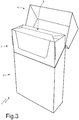
- the external container 2 has an open upper end and is provided with a lid 4, which is cup-shaped and is hinged to the external container 2 along a hinge 5 (illustrated in Figure 2 ) for rotating, relative to the external container 2, between an open position (illustrated in Figure 3 ) and a closed position (illustrated in Figures 1 and 2 ) of the open upper end.
- the wrap 3 encloses a group of cigarettes 5 (illustrated in Figure 5 ) having a parallelepiped shape. Furthermore, the wrap 3 has at the top and at the front a removable portion which is separate from the rest of the wrap 3 by a pre-weakened tearable line; when opening the packet of cigarettes 1 for the first time, the user grabs and tears the removable portion so as to access to the underlying cigarettes of the group of cigarettes 5.
- the packet of cigarettes 1 also comprises a rigid collar 6, which is connected (by means of glueing) U-folded inside the external container 2 so as to partially protrude outside of the open upper end of the external container 2 and engage a corresponding internal surface of the lid 4 when the lid 4 is arranged in the closed position.
- each wrap 3 is made by folding a wrap sheet 8 around the group of cigarettes 5, said wrap sheet 8 provided on one side of the tearable line which delimits the removable portion.
- the external container 2 and the lid 4 are made by folding a blank 8 of conventional type.
- reference numeral 9 indicates, as a whole, a packaging machine which is designed to manufacture the packet of cigarettes 1 described above and works with intermittent motion (i.e. a motion which envisages a cyclical alternation of motion steps and stop steps).
- the packaging machine 9 comprises a frame 10 which rests on the ground by means of a plurality of feet (not illustrated) and is composed of the union of two bodies 11 and 12 arranged side by side; in particular, the body 11 has a front wall and a side wall on which the operating members (partially described below) are arranged, whereas the body 12 has (only) a front wall on which all the operating members (partially described below) are arranged.
- the packaging machine 9 comprises a forming unit A in which the groups of cigarettes 5 are formed in succession, a wrapping unit B in which around each group of cigarettes 2 a respective wrap sheet 7 is wrapped for making a wrap 3, a transfer unit C in which the wraps 3 are transferred two by two towards a following wrapping unit D, and the wrapping unit D in which a collar 6 and a blank 8 are wrapped around each wrap 3 so as to manufacture an external container 2 provided with lid 4.
- the forming unit A of the groups of cigarettes 5 comprises a hopper 13 provided with three output mouths 14 for simultaneously feeding three pairs of groups of cigarettes 5 (i.e. six groups of cigarettes 5) to three respective pockets 15 of a forming conveyor 16 which supports a plurality of pockets 15 (each receiving two groups of cigarettes 5 at a time).
- the forming conveyor 16 comprises a conveyor belt with an annular shape, which is wrapped around two end pulleys (one of which is motorised), supports the pockets 15 and moves at pace for cyclically moving the pockets 15 along a forming path P1 (illustrated in Figure 10 ).
- the forming path P1 develops between an input station S1, in which each group of cigarettes 5 is extracted from an output mouth 14 of the hopper 13 and enters a corresponding pocket 15, and an exchange station S2 in which each group of cigarettes 5 is extracted from the corresponding pocket 15.
- the wrapping unit B comprises a wrap conveyor 17 designed to move two groups of cigarettes 5 side by side (extracted together from a same pocket 15 of the forming conveyor 16 in the exchange station S2) along a horizontal rectilinear wrapping path P2.
- the wrapping path P2 extends from the exchange station S2 in which the wrap conveyor 17 extracts two groups of cigarettes 5 at a time from the corresponding pocket 15 of the forming conveyor 16, passes through a feeding station S3 in which each group of cigarettes 5 couples to a corresponding wrap sheet 7 which U-folds around a group of cigarettes 5, and ends in an exchange station S4 in which two wraps 3 side by side (each formed by a wrap sheet 7 folded around a group of cigarettes 5) leave the wrap conveyor 17 (to enter the transfer unit C).
- the wrap conveyor 17 comprises a conveyor belt 18 with annular shape, which is wrapped around two end pulleys (one of which is motorised) and supports a plurality of pairs of pushing elements 19, each connected to the conveyor belt 18 by means of a support column (narrow, i.e. narrower than the pushing element 19) and is designed to engage a back wall of a corresponding group of cigarettes 5 so as to push the group of cigarettes 5 along the wrapping path P2.
- the wrap conveyor 17 comprises two twin horizontal channels, which are parallel and side by side, each delimited at least at the bottom and on the side (preferably also at the top in the initial part thereof), is arranged along the wrapping path P2, and contains inside therein each group of cigarettes 5 while the group of cigarettes 5 moves along the wrapping path P2 pushed at the back by a corresponding pushing element 19.
- each wrap sheet 7 is arranged to be intercepted by a corresponding group of cigarettes 5 around which the wrap sheet 7 U-folds; in other words, each group of cigarettes 5 moving along the wrapping path P2 intercepts a corresponding wrap sheet 7 arranged in the feeding station S3 determining the U-folding of the wrap sheet 7.
- the packaging machine 9 comprises a feeding device 20 which cyclically feeds pairs of wrap sheets 7 into the feeding station S3, i.e. arranges each pair of wrap sheets 7 in the feeding station S3 so that the wrap sheets 7 are intercepted by two corresponding groups of cigarettes 5 moving along the wrapping path P2.
- the feeding device 20 comprises an unwinding station in which a wrapping material band 21 is unwound by a coil 22 and is moved (passing next to the hopper 13) towards a cutting member 23 of known type which is arranged above the feeding station S3 and cyclically carries out both a longitudinal cut of the wrapping material band 21, and a transverse cut of the wrapping material band 21 so as to separate from the wrapping material band 21 pairs of wrap sheets 7.
- the feeding device 20 could also comprise a processing member (for example an embosser) which is arranged between the unwinding station and the cutting member 23 and carries out a processing (for example an embossing) of the wrapping material band 21.
- the wrapping unit B comprises a pair of folding devices 24 which are arranged along the wrapping path P2 downstream of the feeding station S3 and are designed to fold two open side ends of each wrap sheet 7 U-folded around a corresponding group of cigarettes 5 for forming a tubular wrap having an open back end.
- each folding device 24 comprises only folding profiles (i.e. folding helixes) which are fixed (i.e. totally devoid of parts in movement) and are arranged on opposite sides of the wrapping path P2.
- the wrapping unit B comprises a pair of folding devices 25 which are arranged along the wrapping path P2 downstream of the folding devices 24 and are designed to complete the folding of each wrap sheet 7 around the corresponding group of cigarettes 5 (and thus end the making of the wrap 3) so as to close the open back end (i.e. previously left open by the corresponding folding device 24).
- the wrapping path P2 begins in the transfer station S2 (in which the groups of cigarettes 5 enter two at a time the wrap conveyor 17) and ends in the exchange station S4 (in which the wraps 3 leave the wrap conveyor 17 two at a time for entering the transfer unit C).
- the packaging machine 9 comprises a feeding conveyor 26 which receives the wraps 3 from the transfer unit C (as better described below) and moves the wraps 3 along a feeding path P3 which is rectilinear and perpendicular to the wrapping path P2 up to an exchange station S5 (in which the wraps 3 leave the feeding conveyor 26).
- the feeding conveyor 26 comprises a conveyor belt with annular shape, which is wrapped around two end pulleys (one of which is motorised), supports a plurality of feeding pockets 27 each designed to house a corresponding wrap 3, and moves at pace for cyclically moving the feeding pockets 27 along the feeding path P3 from the transfer unit C to the exchange station S5.
- the transfer unit C is arranged between the wrap conveyor 17 and the feeding conveyor 26, cyclically receives from the wrap conveyor 17 and in the exchange station S4 a pair of wraps 3, which are arranged at an input distance I from one another (illustrated in Figure 14 ), moves the two wraps 3 close to/away from one another so as to arrange them at an output distance O from one another (illustrated in Figure 14 ) different from the input distance I, and thus hands over the two wraps 3 to two respective feeding pockets 27 of the feeding conveyor 26.
- the output distance O can be greater (according to a variant not illustrated) or smaller (according to what illustrated in the accompanying figures) than the input distance I; i.e.
- the transfer unit C can move away (according to a variant not illustrated) or move close (according to what illustrated in the accompanying figures) the two wraps 3 which are transferred together.
- the input distance I could be comprised between 40 and 60 mm
- di output distance O could be comprised between 50 and 100 mm.
- the wrap conveyor 17 cyclically moves along the wrapping path P2 a pair of wraps 3, which are arranged at the input distance I from one another, whereas the feeding conveyor 26 moves the feeding pockets 27 thereof containing the wraps 3 arranged at an output distance O from one another along the feeding path P3.
- the transfer unit C comprises four transfer pockets 28, 29, 30 and 31, each designed to house a respective wrap 3. Furthermore, the transfer unit C comprises two output stations S7 and S8 and one input station S6 arranged between the two output stations S7 and S8 (and arranged in the area of the exchange station S4).
- the transfer unit C comprises an insertion device 32 (schematically illustrated in Figure 14 ) which is designed to simultaneously insert two wraps 3 received together from the wrap conveyor 17 and arranged at the input distance I from one another, into the transfer pocket 28 and into the transfer pocket 29 which are together in the input station S6 (as illustrated in Figures 14 , 15 and 16 ) or into the transfer pocket 30 and into the transfer pocket 31 which are together in the input station S6 (as illustrated in Figures 18 , 19 and 20 ).
- an insertion device 32 (schematically illustrated in Figure 14 ) which is designed to simultaneously insert two wraps 3 received together from the wrap conveyor 17 and arranged at the input distance I from one another, into the transfer pocket 28 and into the transfer pocket 29 which are together in the input station S6 (as illustrated in Figures 14 , 15 and 16 ) or into the transfer pocket 30 and into the transfer pocket 31 which are together in the input station S6 (as illustrated in Figures 18 , 19 and 20 ).
- the transfer unit C comprises an extracting device 33 (schematically illustrated in Figure 14 ) which is designed to simultaneously extract two wraps 3 arranged at the output distance O from one another, from the transfer pocket 28 and from the transfer pocket 29 which are together in the output station S7 (as illustrated in Figures 14 , 15 and 16 ) or from the transfer pocket 30 and from the transfer pocket 31 which are together in the output station S8 (as illustrated in Figures 18 , 19 and 20 ) which is opposite the output station S7 with respect to the input station S6.
- an extracting device 33 (schematically illustrated in Figure 14 ) which is designed to simultaneously extract two wraps 3 arranged at the output distance O from one another, from the transfer pocket 28 and from the transfer pocket 29 which are together in the output station S7 (as illustrated in Figures 14 , 15 and 16 ) or from the transfer pocket 30 and from the transfer pocket 31 which are together in the output station S8 (as illustrated in Figures 18 , 19 and 20 ) which is opposite the output station S7 with respect to the input station S6
- the transfer unit C comprises a moving device 34 (illustrated in Figure 12 and partially in Figure 13 ) which is designed to move along a horizontal moving direction D1 the transfer pocket 28 and the transfer pocket 29 between the input station S6 and the output station S7 and is simultaneously designed to move the transfer pocket 30 and the transfer pocket 31 between the output station S8 and the input station S6; obviously, when the transfer pocket 28 and the transfer pocket 29 are together in the input station S6 (as illustrated in Figures18 , 19 and 20 ) the transfer pocket 30 and the transfer pocket 31 are together in the output station S8, whereas when the transfer pocket 28 and the transfer pocket 29 are together in the output station S7 (as illustrated in Figures 14 , 15 and 16 ) the transfer pocket 30 and the transfer pocket 31 are together in the input station S6.
- a moving device 34 illustrated in Figure 12 and partially in Figure 13
- the transfer unit C comprises a moving device 34 (illustrated in Figure 12 and partially in Figure 13 ) which is designed to move along a horizontal moving direction D1 the transfer pocket 28 and the transfer pocket
- the input station S6 and the output stations S7 and S8 are aligned with one another along the moving direction D1 and, as said in the foregoing, the input station S6 is between the two output stations S7 and S8.
- the four transfer pockets 28, 29, 30 and 31 are aligned with one another along the moving direction D1; furthermore, the transfer pocket 28 and the transfer pocket 29 are arranged on one side whereas the transfer pocket 30 and the transfer pocket 31 are arranged on the opposite side so that the transfer pocket 29 and the transfer pocket 30 are arranged between the transfer pocket 28 and the transfer pocket 31 (i.e. the transfer pockets 29 and 30 are in the middle whereas the transfer pockets 28 and 31 are at the ends).
- the moving device 34 comprises an actuator element 35 (substantially a bar arranged horizontally along the moving direction D1) which is mounted axially sliding so as to alternatively move forwards and backwards along the moving direction D1; the actuator element 35 moves the transfer pockets 29 and 30, i.e. the transfer pockets 29 and 30 are mounted sliding on a fixed guide and are connected to the actuator element 35 and thus move together with the actuator element 35 (i.e. the two transfer pockets 29 and 30 always move in a synchronous manner).
- an actuator element 35 substantially a bar arranged horizontally along the moving direction D1
- the actuator element 35 moves the transfer pockets 29 and 30, i.e. the transfer pockets 29 and 30 are mounted sliding on a fixed guide and are connected to the actuator element 35 and thus move together with the actuator element 35 (i.e. the two transfer pockets 29 and 30 always move in a synchronous manner).
- the moving device 34 comprises an actuator element 36 (substantially a bar arranged horizontally along the moving direction D1) which is separate from and independent of the actuator element 35, is mounted axially sliding so as to alternatively move forwards and backwards along the moving direction D1, and is arranged parallel and next to the actuator element 35; the actuator element 36 moves the transfer pockets 28 and 31, i.e. the transfer pockets 28 and 31 are mounted sliding on a fixed guide and are connected to the pushing element 36 and thus move together with the actuator element 36 (i.e. the two transfer pockets 28 and 31 always move in a synchronous manner).
- the two transfer pockets 29 and 30 always have the same motion law (imposed by the actuator element 35) which is different from the motion law (imposed by the actuator element 36) of the two transfer pockets 28 and 31 (which always have the same motion law).
- the moving device 34 always moves along the moving direction D1 the two actuator elements 35 and 36 in the same way and causing the two actuator elements 35 and 36 to travel respective differentiated strokes C1 and C2 (illustrated in Figures 16 , 17 , 20 and 21 ) i.e. causing the actuator elements 35 and 36 to travel different distances.
- the moving device 34 causes the actuator element 35 (thus the transfer pockets 29 and 30) to travel a stroke C1 which is always greater in both ways with respect to a stroke C2 travelled by the actuator element 36 (thus by the transfer pockets 28 and 31).
- the moving device 34 comprises an operating member 37 which moves the actuator element 35 along the moving direction D1 alternatively in both ways, and an operating member 38 (substantially twin of the operating member 37) which moves the actuator element 36 along the moving direction D1 alternatively in both ways.
- the moving device 34 comprises one single common electric motor 39: the operating member 37 transmits the motion from the common electric motor 39 to the actuator element 35 and analogously the operating member 38 transmits the motion from the common electric motor 39 to the actuator element 36.
- the operating member 37 comprises a rocker arm 40 which is hinged at the centre to a fixed frame 41 so as to rotate around a horizontal rotation axis 42 and is connected (hinged) at an upper end to the actuator element 35;
- the operating member 38 comprises a rocker arm 43 which is arranged next to the rocker arm 40, is hinged at the centre to the fixed frame 41 so as to rotate around a horizontal rotation axis 44 (parallel to the rotation axis 42) and is connected (hinged) at an upper end to the support element 36.
- connection arm 45 so as to rotate together around the respective rotation axes 42 and 44; i.e. the connection arm 45 is hinged to the lower ends of the two rocker arms 40 and 43 (on the opposite side of the actuator elements 35 and 36 with respect to the rotation axes 42 and 44) so as to make the two rocker arms 40 and 43 angularly integral to one another.
- the common electric motor 39 transmits the rotation movement only to the rocker arm 40 (which in turn transmits the rotation movement to the other rocker arm 43 through the connection arm 45) by means of an eccentric arm 46 which is hinged to a lever 47 angularly integral to the rocker arm 40.
- the operating member 37 comprises a first electric motor and the operating member 38 comprises a second electric motor separate from and independent of the first electric motor.
- the operating member 38 comprises a second electric motor separate from and independent of the first electric motor.
- the insertion device 32 comprises two pushing elements 48 which are arranged in the area of the input station S6 and are movable perpendicularly to the moving direction D1 along a main horizontal direction D2; furthermore, the extracting device 33 comprises two pairs of pushing elements 49 which are arranged in the area of the output stations S7 and S8 and are movable perpendicularly to the moving direction D1 along the main horizontal direction D2.
- the transfer assembly C comprises a rigid common support element 50 which supports both the two pushing elements 48 of the input station S6, and the two pairs of pushing elements 49 of the output stations S7 and S8; in this manner all the pushing elements 48 and 49 always move together with the same motion law.
- the transfer assembly C comprises a moving device 51 (partially illustrated in Figure 13 and using an articulated quadrilateral) which alternatively moves the support element 50 both along the main horizontal direction D2, which is perpendicular to the moving direction D1, and along a secondary vertical direction D3, which is perpendicular to the main direction D2 and perpendicular to the moving direction D1.
- the moving device 51 causes the support element 50 (thus the pushing elements 48 and 49 carried by the support element 50) to travel a work stroke (in which the pushing elements 48 and 49 push respective wraps 3) by moving the support element 50 only along the main direction D2 and causes the support element 50 to travel a return stroke (in which the pushing elements 48 and 49 do not touch any wrap 3) by moving the support element 50 in the secondary direction D3 and downwards, then in the main direction D2 with an opposite way relative to the work stroke and, finally, in the secondary direction D3 and upwards.
- the support element 50 lowers so as not to interfere with the wraps 3.
- the transfer pockets 28, 29, 30 and 31 have at the bottom a slit through which a thin stem passes which connects the pushing elements 48 and 49 to the rest of the support element 50.
- the movement impressed on the support element 50 by the moving device 51 could be used also for completing the folding of the wraps 3; i.e. folding elements are also connected to the support element 50, said folding elements, by effect of the movement of the support element 50, perform final folding operations on the wraps 3.
- the transfer pockets 30 and 31 are stationary and are in the input station S6 in alignment with the wrap conveyor 17 and thus ready to receive two wraps 3 which come from the wrap conveyor 17 and are arranged at the input distance I from one another; simultaneously, the transfer pockets 28 and 29 are stationary and are in the output station S7 in alignment with two respective feeding pockets 27 of the feeding conveyor and thus ready to hand over two wraps 3 to the two feeding pockets 27.
- the pushing elements 48 and 49 travel the work stroke thereof: the pushing elements 48 insert two wraps 3, which are arranged at the input distance I from one another, into the transfer pockets 30 and 31 which are in the input station S6 and simultaneously the pushing elements 49 extract two wraps 3 which are arranged at the output distance O from one another, from the transfer pockets 28 and 29 which are in the output station S7 and insert the two wraps 3 into two corresponding feeding pockets 27 of the feeding conveyor 26.
- the two pushing elements 49 of the output station S8 travel the work stoke thereof which is carried out loadless though since the transfer pockets 30 and 31 are not present in the output station S8.
- the transfer pockets 28 and 29 are stationary and are in the input station S6 in alignment with the wrap conveyor 17 and thus ready to receive two wraps 3, which are arranged at the input distance I from one another and come from the wrap conveyor 17; at the same time, the transfer pockets 30 and 31 are stationary and are in the output station S8 in alignment with two corresponding feeding pockets 27 of the feeding conveyor 26 and thus ready to hand over two wraps 3 (arranged at the output distance O from one another) to the feeding pockets 27.
- the pushing elements 48 and 49 carry out their work stroke: the pushing elements 48 insert two wraps 3, which are arranged at the input distance I from one another, into the transfer pockets 28 and 29 which are in the input station S6 and simultaneously the pushing elements 49 extract two wraps 3 which are arranged at the output distance O from one another from the transfer pockets 30 and 31 which are in the output station S8 and insert the two wraps 3 into respective feeding pockets 27 of the feeding conveyor 26.
- the two pushing elements 49 of the output station S7 carry out the work stroke thereof which is carried out loadless though since the transfer pockets 28 and 29 are not present in the output station S7.
- the feeding conveyor 26 carries out the feed steps thereof so as to move, from the output stations S7 and S8 and towards the exchange station S5, the full (i.e. containing respective wraps 3) feeding pockets 27 and replace, in the output stations S7 and S8, the full feeding pockets 27 with as many empty feeding pockets 27.
- the feeding conveyor 26 moves along the feeding path P3, travelling a stroke, which is equal to the output distance O, at a double rate relative to the movement of the extracting device and of the insertion device 32 (i.e. relative to a movement of the pushing elements 48 and 49 which are mounted on the same common support element 50).
- the feeding conveyor 26 has to move along the feeding path P3, travelling a stroke, which is equal to the output distance O, at a rate of 500 times per minute carrying each time a feeding pocket 27 containing a wrap 3 into the exchange station S5.
- FIGS 22-25 illustrate a simplified version of the transfer unit C, in which instead of four transfer pockets 28, 29, 30 and 31 connected to the two actuator elements 35 and 36, only one transfer pocket 30 connected to the actuator element and one transfer pocket 31 connected to the support element 36 are present; i.e. the transfer pockets 28 and 29 have been disassembled (eliminated). Consequently, only the input station S6 and the output station S8 (which remains the only one since the output station S7 is no longer provided) are used.
- the transfer pockets 30 and 31 are stationary and are in the input station S6 in alignment with the wrap conveyor 17 and thus ready to receive two wraps 3 coming from the wrap conveyor 17 and are arranged at the input distance I from one another.
- the pushing elements 48 and 49 travel the work stroke thereof: the pushing elements 48 insert two wraps 3, which are arranged at the input distance I from one another, into the transfer pockets 30 and 31 which are in the input station S6, whereas the two pushing elements 49 of the output station S8 travel the work stroke thereof which is carried out loadless though since the transfer pockets 30 and 31 are not present in the output station S8.
- the transfer pockets 30 and 31 move in the same way along the moving direction D1: the transfer pocket 31 travels the shorter stroke C2, whereas the transfer pocket 30 travels the longer stroke C1 so as to move the transfer pockets 30 and 31 from the input station S6 to the output station S8.
- the transfer pockets 30 and 31 moving from the input station S6 to the output station S8 decrease the mutual distance thereof (from the input distance I to the output distance O since the difference between the two strokes C2 and C1 is equal to the difference between the input distance I and the output distance O).
- the transfer pockets 30 and 31 are stationary and are in the output station S8 in alignment with two corresponding feeding pockets 27 of the feeding conveyor 26 and thus ready to hand over two wraps 3 (arranged at the output distance O from one another) to the feeding pockets 27.
- the pushing elements 48 and 49 travel the work stroke thereof: the pushing elements 48 travel the work stroke thereof loadless since the transfer pockets 30 and 31 are not present in the input station S6 and simultaneously the pushing elements 49 extract two wraps 3 which are arranged at the output distance O from one another, from the transfer pockets 30 and 31 which are in the output station S8 and insert the two wraps 3 into respective feeding pockets 27 of the feeding conveyor 26.
- the transfer pockets 30 and 31 move in the same way along the moving direction D1: the transfer pocket 31 travels the shorter stroke C2 whereas the transfer pocket 30 travels the longer stroke C1 so as to move the transfer pockets 30 and 31 from the output station S8 to the input station S6.
- the transfer pockets 30 and 31 moving from the output station S8 to the input station S6 increase the mutual distance thereof (from the output distance O to the input distance I).
- the embodiment illustrated in Figures 12-21 which provides for the presence of the four transfer pockets 28, 29, 30 and 31, allows extending the pauses between the movements of the transfer pockets 28, 29, 30 and 31 along the moving direction D1 and thus allows transferring also relatively "long" (i.e. more developed along the main direction D2) wraps which need more time for entering/exiting from the transfer pockets 28, 29, 30 and 31 (due to the length thereof); on the other hand, the embodiment illustrated in Figures 12-21 , which provides for the presence of the four transfer pockets 28, 29, 30 and 31, is bulkier, i.e. has a greater development along the moving direction D1.
- the embodiment illustrated in Figures 22-25 which provides for the presence of only two transfer pockets 30 and 31, is more compact, i.e. has a smaller development along the moving direction D1; on the other hand, the embodiment illustrated in Figures 22-25 , which provides for the presence of only two transfer pockets 30 and 31, requires shorter pauses between the movements of the transfer pockets 30 and 31 along the moving direction D1 and thus allows transferring only relatively "short" (i.e. less developed along the main direction D2) wraps 3 which need less time for entering/exiting from the transfer pockets 30 and 31 (by effect of their limited length).
- the movement of the various components (wrap wheels, feeding conveyors, pushing elements, movable folding elements...) of the packaging machine 9 is carried out by means of respective electric motors which are mechanically independent of one another and are synchronised (i.e. moved in step) in a virtual manner (i.e. not by means of a physical constraint, but by means of a control constraint).
- one electric motor is considered as reference ( “master” ) and all the other electric motors ( “slaves” ) track the position of the electric motor of reference ( “master” ) .
- the linear movements i.e.
- a rotating electric motor which leads into rotation a pinion which engages with a rack; i.e. a "pinion-rack” mechanism is used for transforming the rotary movement generated by the electric motor into a linear movement.
- the transfer unit C described above has many advantages.
- the transfer unit C described above allows operating at a high production speed (i.e. with a high number of wraps 3 produced in the time unit) without damaging the wraps 3.
- the transfer unit C described above allows changing the size of the packets of cigarettes 1 in a relatively simple and fast manner.
- the transfer unit C described above is compact and has an optimum accessibility to all the components thereof (a particularly useful characteristic during the execution of a size change).
Abstract
Description
- This patent application claims priority from
Italian patent application no. 102020000014167 filed on 15/06/2020 - The present invention relates to a transfer unit and to a transfer method to transfer pairs of wraps containing groups of smoking articles, in particular groups of cigarettes, changing the mutual distance thereof.
- For several years now, a packet of cigarettes is known commercially called "twin" and comprising a rigid external container which houses inside therein two groups of cigarettes that are identical (i.e. "twins" wherefrom the commercial name of the packet of cigarettes), which are arranged side by side and are wrapped up in corresponding wrap sheets.
- Patent No.
EP3362365B1 describes a packaging machine for producing a "twin" packet of cigarettes comprising: a forming unit in which the groups of cigarettes are formed in succession, a first wrapping unit provided with wheels with horizontal axis in which a wrap sheet is folded around each group of cigarettes so as to form a corresponding wrap, a grouping (coupling) unit provided with a wheel in which the wraps are grouped (coupled) two by two so as to form the content of the packet of cigarettes, and a second wrapping unit provided with wheels with horizontal axis in which a collar and a blank are folded around each pair of wraps so as to form an external container. - Also
patent No. US4258528A describes a packaging machine for producing a "twin" packet of cigarettes comprising: a forming unit in which the groups of cigarettes are formed in succession, a first wrapping unit provided with linear conveyors in which a wrap sheet is folded around each group of cigarettes so as to form a corresponding wrap, a grouping (coupling) unit in which the wraps are grouped (coupled) two by two so as to form the content of the packets of cigarettes, and a second wrapping unit provided with a wheel with vertical axis in which a collar and a blank are folded around each pair of wraps so as to form an external container. - Over the last few years, the production of packets of cigarettes has been more and more frequently suited to the extemporary requests of the market and consequently it is necessary to modify with a certain frequency a packaging machine so as to change the type (i.e. the size) of the packets of cigarettes which are produced. For example, it can occur that a packaging machine designed to produce a "twin" packet of cigarettes (i.e. containing two wrapped groups of cigarettes which are distinct and identical) has to be modified so as to produce a traditional packet of cigarettes (i.e. containing one single wrapped group of cigarettes); in this case, the problem is how to replace the grouping unit (in which the wraps are grouped two by two) with a transfer unit which transfers the wraps from two input conveyors parallel to one another (constituting the output of the first wrapping unit) to one single output conveyor (constituting the input of the second wrapping unit) perpendicular to the input conveyors.
- The purpose of the present invention is to provide a transfer unit and a transfer method for transferring pairs of wraps containing groups of smoking articles changing the mutual distance thereof, said transfer unit and transfer method being simple and compact to implement, allowing operating at a high production speed (measured as packets of cigarettes transferred in the time unit), and allowing quickly carrying out the size change operations.
- In accordance with the present invention, a transfer unit and a transfer method are provided for transferring pairs of wraps containing groups of smoking articles changing the mutual distance thereof, according to what claimed in the appended claims.
- The claims describe embodiments of the present invention forming integral part of the present description.
- The present invention will now be described with reference to the accompanying drawings, which illustrate a non-limiting example embodiment thereof, wherein:
-
Figure 1 is a front perspective view, in a closed configuration, of a rigid packet of cigarettes; -
Figure 2 is a back perspective view of the packet of cigarettes ofFigure 1 in a closed configuration; -
Figure 3 is a front perspective view of the packet of cigarettes ofFigure 1 in an open configuration; -
Figure 4 is a front perspective view of a wrap of the packet ofFigure 1 ; -
Figure 5 is a perspective view of a group of cigarettes contained in the wrap ofFigure 4 ; -
Figure 6 is a plan view of a wrap sheet used for making the wrap ofFigure 4 ; -
Figure 7 is a plan view of a collar of the packet of cigarettes ofFigure 1 ; -
Figure 8 is a plan view of a blank used for making an external container provided with hinged lid of the packet of cigarettes ofFigure 1 ; -
Figure 9 is a schematic perspective view, with parts removed for clarity, of a packaging machine which produces the packet of cigarettes ofFigure 1 and is manufactured in accordance with the present invention; -
Figure 10 is a schematic plan view of part of the packaging machine ofFigure 9 ; -
Figure 11 is a schematic side view of part of the packaging machine ofFigure 9 ; -
Figures 12 and13 are two different perspective views of a transfer unit of the packaging machine ofFigure 9 with parts removed for clarity; -
Figures 14-21 schematically illustrate the functioning of the grouping unit ofFigures 12 and13 ; and -
Figures 22-25 schematically illustrate the functioning of a simplified variant of the grouping unit ofFigures 12 and13 . - In
Figures 1, 2 and3 ,reference numeral 1 indicates, as a whole, a rigid packet of cigarettes. The packet ofcigarettes 1 comprises anexternal container 2 made of cardboard or rigid paperboard and cup-shaped and a wrap 3 (better illustrated inFigure 4 ) housed inside thecontainer 2. - The
external container 2 has an open upper end and is provided with alid 4, which is cup-shaped and is hinged to theexternal container 2 along a hinge 5 (illustrated inFigure 2 ) for rotating, relative to theexternal container 2, between an open position (illustrated inFigure 3 ) and a closed position (illustrated inFigures 1 and 2 ) of the open upper end. - The
wrap 3 encloses a group of cigarettes 5 (illustrated inFigure 5 ) having a parallelepiped shape. Furthermore, thewrap 3 has at the top and at the front a removable portion which is separate from the rest of thewrap 3 by a pre-weakened tearable line; when opening the packet ofcigarettes 1 for the first time, the user grabs and tears the removable portion so as to access to the underlying cigarettes of the group ofcigarettes 5. - According to what illustrated in
Figures 3 and7 , the packet ofcigarettes 1 also comprises arigid collar 6, which is connected (by means of glueing) U-folded inside theexternal container 2 so as to partially protrude outside of the open upper end of theexternal container 2 and engage a corresponding internal surface of thelid 4 when thelid 4 is arranged in the closed position. According to what illustrated inFigure 6 , eachwrap 3 is made by folding awrap sheet 8 around the group ofcigarettes 5, saidwrap sheet 8 provided on one side of the tearable line which delimits the removable portion. According to what illustrated inFigure 8 , theexternal container 2 and thelid 4 are made by folding a blank 8 of conventional type. - In
Figure 9 , reference numeral 9 indicates, as a whole, a packaging machine which is designed to manufacture the packet ofcigarettes 1 described above and works with intermittent motion (i.e. a motion which envisages a cyclical alternation of motion steps and stop steps). - The packaging machine 9 comprises a
frame 10 which rests on the ground by means of a plurality of feet (not illustrated) and is composed of the union of twobodies body 11 has a front wall and a side wall on which the operating members (partially described below) are arranged, whereas thebody 12 has (only) a front wall on which all the operating members (partially described below) are arranged. - The packaging machine 9 comprises a forming unit A in which the groups of
cigarettes 5 are formed in succession, a wrapping unit B in which around each group of cigarettes 2 arespective wrap sheet 7 is wrapped for making awrap 3, a transfer unit C in which thewraps 3 are transferred two by two towards a following wrapping unit D, and the wrapping unit D in which acollar 6 and a blank 8 are wrapped around eachwrap 3 so as to manufacture anexternal container 2 provided withlid 4. - The forming unit A of the groups of
cigarettes 5 comprises ahopper 13 provided with threeoutput mouths 14 for simultaneously feeding three pairs of groups of cigarettes 5 (i.e. six groups of cigarettes 5) to threerespective pockets 15 of a formingconveyor 16 which supports a plurality of pockets 15 (each receiving two groups ofcigarettes 5 at a time). The formingconveyor 16 comprises a conveyor belt with an annular shape, which is wrapped around two end pulleys (one of which is motorised), supports thepockets 15 and moves at pace for cyclically moving thepockets 15 along a forming path P1 (illustrated inFigure 10 ). According to what better illustrated inFigure 10 , the forming path P1 develops between an input station S1, in which each group ofcigarettes 5 is extracted from anoutput mouth 14 of thehopper 13 and enters acorresponding pocket 15, and an exchange station S2 in which each group ofcigarettes 5 is extracted from thecorresponding pocket 15. - According to what illustrated in
Figure 10 , the wrapping unit B comprises awrap conveyor 17 designed to move two groups ofcigarettes 5 side by side (extracted together from asame pocket 15 of the formingconveyor 16 in the exchange station S2) along a horizontal rectilinear wrapping path P2. In particular, the wrapping path P2 extends from the exchange station S2 in which thewrap conveyor 17 extracts two groups ofcigarettes 5 at a time from thecorresponding pocket 15 of the formingconveyor 16, passes through a feeding station S3 in which each group ofcigarettes 5 couples to acorresponding wrap sheet 7 which U-folds around a group ofcigarettes 5, and ends in an exchange station S4 in which two wraps 3 side by side (each formed by awrap sheet 7 folded around a group of cigarettes 5) leave the wrap conveyor 17 (to enter the transfer unit C). - According to what illustrated in
Figure 11 , thewrap conveyor 17 comprises aconveyor belt 18 with annular shape, which is wrapped around two end pulleys (one of which is motorised) and supports a plurality of pairs of pushingelements 19, each connected to theconveyor belt 18 by means of a support column (narrow, i.e. narrower than the pushing element 19) and is designed to engage a back wall of a corresponding group ofcigarettes 5 so as to push the group ofcigarettes 5 along the wrapping path P2. In other words, thewrap conveyor 17 comprises two twin horizontal channels, which are parallel and side by side, each delimited at least at the bottom and on the side (preferably also at the top in the initial part thereof), is arranged along the wrapping path P2, and contains inside therein each group ofcigarettes 5 while the group ofcigarettes 5 moves along the wrapping path P2 pushed at the back by a corresponding pushingelement 19. - Along the wrapping path P2 (and thus in the area of the wrap conveyor 17) a feeding station S3 is present in which each
wrap sheet 7 is arranged to be intercepted by a corresponding group ofcigarettes 5 around which thewrap sheet 7 U-folds; in other words, each group ofcigarettes 5 moving along the wrapping path P2 intercepts acorresponding wrap sheet 7 arranged in the feeding station S3 determining the U-folding of thewrap sheet 7. - The packaging machine 9 comprises a
feeding device 20 which cyclically feeds pairs ofwrap sheets 7 into the feeding station S3, i.e. arranges each pair ofwrap sheets 7 in the feeding station S3 so that thewrap sheets 7 are intercepted by two corresponding groups ofcigarettes 5 moving along the wrapping path P2. According to what illustrated inFigure 9 , thefeeding device 20 comprises an unwinding station in which a wrappingmaterial band 21 is unwound by acoil 22 and is moved (passing next to the hopper 13) towards acutting member 23 of known type which is arranged above the feeding station S3 and cyclically carries out both a longitudinal cut of the wrappingmaterial band 21, and a transverse cut of the wrappingmaterial band 21 so as to separate from the wrappingmaterial band 21 pairs ofwrap sheets 7. Thefeeding device 20 could also comprise a processing member (for example an embosser) which is arranged between the unwinding station and thecutting member 23 and carries out a processing (for example an embossing) of the wrappingmaterial band 21. - According to what illustrated in
Figure 10 , the wrapping unit B comprises a pair offolding devices 24 which are arranged along the wrapping path P2 downstream of the feeding station S3 and are designed to fold two open side ends of eachwrap sheet 7 U-folded around a corresponding group ofcigarettes 5 for forming a tubular wrap having an open back end. Preferably, eachfolding device 24 comprises only folding profiles (i.e. folding helixes) which are fixed (i.e. totally devoid of parts in movement) and are arranged on opposite sides of the wrapping path P2. - According to what illustrated in
Figure 10 , the wrapping unit B comprises a pair offolding devices 25 which are arranged along the wrapping path P2 downstream of thefolding devices 24 and are designed to complete the folding of eachwrap sheet 7 around the corresponding group of cigarettes 5 (and thus end the making of the wrap 3) so as to close the open back end (i.e. previously left open by the corresponding folding device 24). - The wrapping path P2 begins in the transfer station S2 (in which the groups of
cigarettes 5 enter two at a time the wrap conveyor 17) and ends in the exchange station S4 (in which thewraps 3 leave thewrap conveyor 17 two at a time for entering the transfer unit C). According to what illustrated inFigure 9 , the packaging machine 9 comprises afeeding conveyor 26 which receives thewraps 3 from the transfer unit C (as better described below) and moves thewraps 3 along a feeding path P3 which is rectilinear and perpendicular to the wrapping path P2 up to an exchange station S5 (in which thewraps 3 leave the feeding conveyor 26). Thefeeding conveyor 26 comprises a conveyor belt with annular shape, which is wrapped around two end pulleys (one of which is motorised), supports a plurality offeeding pockets 27 each designed to house acorresponding wrap 3, and moves at pace for cyclically moving thefeeding pockets 27 along the feeding path P3 from the transfer unit C to the exchange station S5. - As said in the foregoing, the transfer unit C is arranged between the
wrap conveyor 17 and thefeeding conveyor 26, cyclically receives from thewrap conveyor 17 and in the exchange station S4 a pair ofwraps 3, which are arranged at an input distance I from one another (illustrated inFigure 14 ), moves the twowraps 3 close to/away from one another so as to arrange them at an output distance O from one another (illustrated inFigure 14 ) different from the input distance I, and thus hands over the twowraps 3 to tworespective feeding pockets 27 of thefeeding conveyor 26. In general, the output distance O can be greater (according to a variant not illustrated) or smaller (according to what illustrated in the accompanying figures) than the input distance I; i.e. the transfer unit C can move away (according to a variant not illustrated) or move close (according to what illustrated in the accompanying figures) the twowraps 3 which are transferred together. For example, depending on the size of the packet ofcigarettes 1 the input distance I could be comprised between 40 and 60 mm, whereas di output distance O could be comprised between 50 and 100 mm. In particular, thewrap conveyor 17 cyclically moves along the wrapping path P2 a pair ofwraps 3, which are arranged at the input distance I from one another, whereas the feedingconveyor 26 moves the feeding pockets 27 thereof containing thewraps 3 arranged at an output distance O from one another along the feeding path P3. - According to what illustrated in
Figure 14 , the transfer unit C comprises fourtransfer pockets respective wrap 3. Furthermore, the transfer unit C comprises two output stations S7 and S8 and one input station S6 arranged between the two output stations S7 and S8 (and arranged in the area of the exchange station S4). - The transfer unit C comprises an insertion device 32 (schematically illustrated in
Figure 14 ) which is designed to simultaneously insert twowraps 3 received together from thewrap conveyor 17 and arranged at the input distance I from one another, into thetransfer pocket 28 and into thetransfer pocket 29 which are together in the input station S6 (as illustrated inFigures 14 ,15 and16 ) or into thetransfer pocket 30 and into thetransfer pocket 31 which are together in the input station S6 (as illustrated inFigures 18 ,19 and20 ). - The transfer unit C comprises an extracting device 33 (schematically illustrated in
Figure 14 ) which is designed to simultaneously extract twowraps 3 arranged at the output distance O from one another, from thetransfer pocket 28 and from thetransfer pocket 29 which are together in the output station S7 (as illustrated inFigures 14 ,15 and16 ) or from thetransfer pocket 30 and from thetransfer pocket 31 which are together in the output station S8 (as illustrated inFigures 18 ,19 and20 ) which is opposite the output station S7 with respect to the input station S6. - The transfer unit C comprises a moving device 34 (illustrated in
Figure 12 and partially inFigure 13 ) which is designed to move along a horizontal moving direction D1 thetransfer pocket 28 and thetransfer pocket 29 between the input station S6 and the output station S7 and is simultaneously designed to move thetransfer pocket 30 and thetransfer pocket 31 between the output station S8 and the input station S6; obviously, when thetransfer pocket 28 and thetransfer pocket 29 are together in the input station S6 (as illustrated inFigures18 ,19 and20 ) thetransfer pocket 30 and thetransfer pocket 31 are together in the output station S8, whereas when thetransfer pocket 28 and thetransfer pocket 29 are together in the output station S7 (as illustrated inFigures 14 ,15 and16 ) thetransfer pocket 30 and thetransfer pocket 31 are together in the input station S6. - As well illustrated in
Figure 14 , the input station S6 and the output stations S7 and S8 are aligned with one another along the moving direction D1 and, as said in the foregoing, the input station S6 is between the two output stations S7 and S8. As well illustrated inFigure 14 , the fourtransfer pockets transfer pocket 28 and thetransfer pocket 29 are arranged on one side whereas thetransfer pocket 30 and thetransfer pocket 31 are arranged on the opposite side so that thetransfer pocket 29 and thetransfer pocket 30 are arranged between thetransfer pocket 28 and the transfer pocket 31 (i.e. the transfer pockets 29 and 30 are in the middle whereas the transfer pockets 28 and 31 are at the ends). - According to what illustrated in
Figure 12 , the movingdevice 34 comprises an actuator element 35 (substantially a bar arranged horizontally along the moving direction D1) which is mounted axially sliding so as to alternatively move forwards and backwards along the moving direction D1; theactuator element 35 moves the transfer pockets 29 and 30, i.e. the transfer pockets 29 and 30 are mounted sliding on a fixed guide and are connected to theactuator element 35 and thus move together with the actuator element 35 (i.e. the twotransfer pockets device 34 comprises an actuator element 36 (substantially a bar arranged horizontally along the moving direction D1) which is separate from and independent of theactuator element 35, is mounted axially sliding so as to alternatively move forwards and backwards along the moving direction D1, and is arranged parallel and next to theactuator element 35; theactuator element 36 moves the transfer pockets 28 and 31, i.e. the transfer pockets 28 and 31 are mounted sliding on a fixed guide and are connected to the pushingelement 36 and thus move together with the actuator element 36 (i.e. the twotransfer pockets transfer pockets transfer pockets 28 and 31 (which always have the same motion law). - The moving
device 34 always moves along the moving direction D1 the twoactuator elements actuator elements Figures 16 ,17 ,20 and21 ) i.e. causing theactuator elements device 34 causes the actuator element 35 (thus the transfer pockets 29 and 30) to travel a stroke C1 which is always greater in both ways with respect to a stroke C2 travelled by the actuator element 36 (thus by the transfer pockets 28 and 31). - According to what illustrated in
Figure 12 , the movingdevice 34 comprises an operatingmember 37 which moves theactuator element 35 along the moving direction D1 alternatively in both ways, and an operating member 38 (substantially twin of the operating member 37) which moves theactuator element 36 along the moving direction D1 alternatively in both ways. - The moving
device 34 comprises one single common electric motor 39: the operatingmember 37 transmits the motion from the commonelectric motor 39 to theactuator element 35 and analogously the operatingmember 38 transmits the motion from the commonelectric motor 39 to theactuator element 36. According to the (non-limiting) embodiment illustrated inFigure 15 , the operatingmember 37 comprises arocker arm 40 which is hinged at the centre to a fixedframe 41 so as to rotate around a horizontal rotation axis 42 and is connected (hinged) at an upper end to theactuator element 35; analogously, the operatingmember 38 comprises arocker arm 43 which is arranged next to therocker arm 40, is hinged at the centre to the fixedframe 41 so as to rotate around a horizontal rotation axis 44 (parallel to the rotation axis 42) and is connected (hinged) at an upper end to thesupport element 36. The tworocker arms connection arm 45 so as to rotate together around the respective rotation axes 42 and 44; i.e. theconnection arm 45 is hinged to the lower ends of the tworocker arms 40 and 43 (on the opposite side of theactuator elements rocker arms electric motor 39 transmits the rotation movement only to the rocker arm 40 (which in turn transmits the rotation movement to theother rocker arm 43 through the connection arm 45) by means of aneccentric arm 46 which is hinged to alever 47 angularly integral to therocker arm 40. - As illustrated in
Figure 12 , it is apparent that the extension of the rocker arm 40 (i.e. the arm of therocker arm 40 with respect to the rotation axis 42) is greater than the extension of the rocker arm 43 (i.e. of the arm of therocker arm 43 with respect to the rotation axis 44); in this manner, the rotation being equal, therocker arm 40 impresses on the transfer actuator element 35 (which carries the transfer pockets 29 and 30) the stroke C1 which is greater than the stroke C2 impressed by therocker arm 43 on the transfer actuator element 36 (which carries the transfer pockets 28 and 31). - When a size change operation requires to modify the strokes C1 and C2 of the
transfer actuator elements 35 and 36 (i.e. of the transfer pockets 28, 29, 30 and 31) it may be necessary to replace some components of the operatingmembers 37 and 38 (for example therocker arms 40 and 43); such operation is anyway relatively simple and fast. - According to a different embodiment not illustrated, the operating
member 37 comprises a first electric motor and the operatingmember 38 comprises a second electric motor separate from and independent of the first electric motor. In this manner, when a size change operation requires to modify the strokes C1 and C2 of thetransfer actuator elements 35 and 36 (i.e. of the transfer pockets 28, 29, 30 and 31) it is sufficient to update the control software of the two electric motors without any replacement of physical components. - According to what illustrated in
Figure 14 , theinsertion device 32 comprises two pushingelements 48 which are arranged in the area of the input station S6 and are movable perpendicularly to the moving direction D1 along a main horizontal direction D2; furthermore, the extractingdevice 33 comprises two pairs of pushingelements 49 which are arranged in the area of the output stations S7 and S8 and are movable perpendicularly to the moving direction D1 along the main horizontal direction D2. - According to what illustrated in
Figure 13 , the transfer assembly C comprises a rigidcommon support element 50 which supports both the two pushingelements 48 of the input station S6, and the two pairs of pushingelements 49 of the output stations S7 and S8; in this manner all the pushingelements Figure 13 and using an articulated quadrilateral) which alternatively moves thesupport element 50 both along the main horizontal direction D2, which is perpendicular to the moving direction D1, and along a secondary vertical direction D3, which is perpendicular to the main direction D2 and perpendicular to the moving direction D1. In particular, the movingdevice 51 causes the support element 50 (thus the pushingelements elements support element 50 only along the main direction D2 and causes thesupport element 50 to travel a return stroke (in which the pushingelements support element 50 in the secondary direction D3 and downwards, then in the main direction D2 with an opposite way relative to the work stroke and, finally, in the secondary direction D3 and upwards. In other words, in the return stroke the support element 50 (thus the pushingelements wraps 3. - It should be noted that, as illustrated in
Figure 12 , the transfer pockets 28, 29, 30 and 31 have at the bottom a slit through which a thin stem passes which connects the pushingelements support element 50. - According to a possible embodiment, the movement impressed on the
support element 50 by the movingdevice 51 could be used also for completing the folding of thewraps 3; i.e. folding elements are also connected to thesupport element 50, said folding elements, by effect of the movement of thesupport element 50, perform final folding operations on thewraps 3. - With reference to
Figures 14-21 , the functioning of the transfer unit C is described below. Initially and as illustrated inFigure 14 , the transfer pockets 30 and 31 are stationary and are in the input station S6 in alignment with thewrap conveyor 17 and thus ready to receive twowraps 3 which come from thewrap conveyor 17 and are arranged at the input distance I from one another; simultaneously, the transfer pockets 28 and 29 are stationary and are in the output station S7 in alignment with two respective feeding pockets 27 of the feeding conveyor and thus ready to hand over twowraps 3 to the two feeding pockets 27. - At this point, as illustrated in
Figures 15 and16 , while the transfer pockets 28, 29, 30 and 31 are stationary, the pushingelements elements 48 insert twowraps 3, which are arranged at the input distance I from one another, into the transfer pockets 30 and 31 which are in the input station S6 and simultaneously the pushingelements 49 extract twowraps 3 which are arranged at the output distance O from one another, from the transfer pockets 28 and 29 which are in the output station S7 and insert the twowraps 3 into two corresponding feeding pockets 27 of the feedingconveyor 26. In this step, also the two pushingelements 49 of the output station S8 travel the work stoke thereof which is carried out loadless though since the transfer pockets 30 and 31 are not present in the output station S8. - Subsequently, as illustrated in
Figure 17 , all the transfer pockets 28, 29, 30 and 31 move in the same way along the moving direction D1: the transfer pockets 28 and 31 travel the shorter stroke C2 whereas the transfer pockets 29 and 30 travel the longer stroke C1 so as to move the transfer pockets 28 and 29 from the output station S7 to the input station S6 and to move the transfer pockets 30 and 31 from the input station S6 to the output station S8. By effect of the differentiated strokes C1 and C2, while the transfer pockets 28 and 29 moving from the output station S7 to the input station S6 increase the mutual distance thereof (from the output distance O to the input distance I since the difference between the two strokes C1 and C2 is equal to the difference between the input distance I and the output distance O), the transfer pockets 30 and 31 moving from the input station S6 to the output station S8 decrease the mutual distance thereof (from the input distance I to the output distance O since the difference between the two strokes C2 and C1 is equal to the difference between the input distance I and the output distance O). - As illustrated in
Figures 18 and19 , at the end of the movement the transfer pockets 28 and 29 are stationary and are in the input station S6 in alignment with thewrap conveyor 17 and thus ready to receive twowraps 3, which are arranged at the input distance I from one another and come from thewrap conveyor 17; at the same time, the transfer pockets 30 and 31 are stationary and are in the output station S8 in alignment with two corresponding feeding pockets 27 of the feedingconveyor 26 and thus ready to hand over two wraps 3 (arranged at the output distance O from one another) to the feeding pockets 27. - At this point, and as illustrated in
Figures 19 and20 , while the transfer pockets 28, 29, 30 and 31 are stationary, the pushingelements elements 48 insert twowraps 3, which are arranged at the input distance I from one another, into the transfer pockets 28 and 29 which are in the input station S6 and simultaneously the pushingelements 49 extract twowraps 3 which are arranged at the output distance O from one another from the transfer pockets 30 and 31 which are in the output station S8 and insert the twowraps 3 into respective feeding pockets 27 of the feedingconveyor 26. In this step, also the two pushingelements 49 of the output station S7 carry out the work stroke thereof which is carried out loadless though since the transfer pockets 28 and 29 are not present in the output station S7. - Subsequently and as illustrated in
Figure 21 , all the transfer pockets 28, 29, 30 and 31 move in the same way along the moving direction D1: the transfer pockets 28 and 31 carry out the shorter stroke C2 whereas the transfer pockets 29 and 30 carry out the longer stroke C1 so as to move the transfer pockets 28 and 29 from the input station S6 to the output station S7 and so as to move the transfer pockets 30 and 31 from the output station S8 to the input station S6. By effect of the differentiated strokes C1 and C2, while the transfer pockets 30 and 31 moving from the output station S8 to the input station S6 increase the mutual distance thereof (from the output distance O to the input distance I), the transfer pockets 28 and 29 moving from the input station S6 to the output station S7 reduce the mutual distance thereof (from the input distance I to the output distance O). At this point, the transfer unit C is in the situation illustrated inFigure 14 and the cycle described above restarts. - Obviously, during the movements of the transfer pockets 28, 29, 30 and 31 also the feeding
conveyor 26 carries out the feed steps thereof so as to move, from the output stations S7 and S8 and towards the exchange station S5, the full (i.e. containing respective wraps 3) feeding pockets 27 and replace, in the output stations S7 and S8, the full feeding pockets 27 with as many empty feeding pockets 27. In particular, the feedingconveyor 26 moves along the feeding path P3, travelling a stroke, which is equal to the output distance O, at a double rate relative to the movement of the extracting device and of the insertion device 32 (i.e. relative to a movement of the pushingelements elements wraps 3, thus moving twowraps 3 each time), the feedingconveyor 26 has to move along the feeding path P3, travelling a stroke, which is equal to the output distance O, at a rate of 500 times per minute carrying each time afeeding pocket 27 containing awrap 3 into the exchange station S5. -
Figures 22-25 illustrate a simplified version of the transfer unit C, in which instead of fourtransfer pockets actuator elements transfer pocket 30 connected to the actuator element and onetransfer pocket 31 connected to thesupport element 36 are present; i.e. the transfer pockets 28 and 29 have been disassembled (eliminated). Consequently, only the input station S6 and the output station S8 (which remains the only one since the output station S7 is no longer provided) are used. - Initially and as illustrated in
Figure 22 , the transfer pockets 30 and 31 are stationary and are in the input station S6 in alignment with thewrap conveyor 17 and thus ready to receive twowraps 3 coming from thewrap conveyor 17 and are arranged at the input distance I from one another. - At this point, as illustrated in
Figure 23 , while the transfer pockets 30 and 31 are stationary, the pushingelements elements 48 insert twowraps 3, which are arranged at the input distance I from one another, into the transfer pockets 30 and 31 which are in the input station S6, whereas the two pushingelements 49 of the output station S8 travel the work stroke thereof which is carried out loadless though since the transfer pockets 30 and 31 are not present in the output station S8. - Subsequently and as illustrated in
Figure 23 , the transfer pockets 30 and 31 move in the same way along the moving direction D1: thetransfer pocket 31 travels the shorter stroke C2, whereas thetransfer pocket 30 travels the longer stroke C1 so as to move the transfer pockets 30 and 31 from the input station S6 to the output station S8. By effect of the differentiated strokes C1 and C2, the transfer pockets 30 and 31 moving from the input station S6 to the output station S8 decrease the mutual distance thereof (from the input distance I to the output distance O since the difference between the two strokes C2 and C1 is equal to the difference between the input distance I and the output distance O). - As illustrated in
Figure 24 , at the end of the movement the transfer pockets 30 and 31 are stationary and are in the output station S8 in alignment with two corresponding feeding pockets 27 of the feedingconveyor 26 and thus ready to hand over two wraps 3 (arranged at the output distance O from one another) to the feeding pockets 27. - At this point, and as illustrated in
Figure 25 , while the transfer pockets 30 and 31 are stationary, the pushingelements elements 48 travel the work stroke thereof loadless since the transfer pockets 30 and 31 are not present in the input station S6 and simultaneously the pushingelements 49 extract twowraps 3 which are arranged at the output distance O from one another, from the transfer pockets 30 and 31 which are in the output station S8 and insert the twowraps 3 into respective feeding pockets 27 of the feedingconveyor 26. - Subsequently and as illustrated in
Figure 25 , the transfer pockets 30 and 31 move in the same way along the moving direction D1: thetransfer pocket 31 travels the shorter stroke C2 whereas thetransfer pocket 30 travels the longer stroke C1 so as to move the transfer pockets 30 and 31 from the output station S8 to the input station S6. By effect of the differentiated strokes C1 and C2, the transfer pockets 30 and 31 moving from the output station S8 to the input station S6 increase the mutual distance thereof (from the output distance O to the input distance I). - At this point, the transfer unit C is in the situation illustrated in
Figure 22 and the cycle described above restarts. - The embodiment illustrated in
Figures 12-21 , which provides for the presence of the fourtransfer pockets Figures 12-21 , which provides for the presence of the fourtransfer pockets - Instead, the embodiment illustrated in
Figures 22-25 , which provides for the presence of only twotransfer pockets Figures 22-25 , which provides for the presence of only twotransfer pockets - According to a preferred but non-binding embodiment, the movement of the various components (wrap wheels, feeding conveyors, pushing elements, movable folding elements...) of the packaging machine 9 is carried out by means of respective electric motors which are mechanically independent of one another and are synchronised (i.e. moved in step) in a virtual manner (i.e. not by means of a physical constraint, but by means of a control constraint). Normally, one electric motor is considered as reference ("master") and all the other electric motors ("slaves") track the position of the electric motor of reference ("master"). In order to obtain the linear movements (i.e. which provide for a movement along a rectilinear trajectory), a rotating electric motor is generally used which leads into rotation a pinion which engages with a rack; i.e. a "pinion-rack" mechanism is used for transforming the rotary movement generated by the electric motor into a linear movement.
- The embodiments described herein can be combined with one another without departing from the scope of protection of the present invention.
- The transfer unit C described above has many advantages.
- First of all, the transfer unit C described above allows operating at a high production speed (i.e. with a high number of
wraps 3 produced in the time unit) without damaging thewraps 3. - Furthermore, the transfer unit C described above allows changing the size of the packets of
cigarettes 1 in a relatively simple and fast manner. - Finally, the transfer unit C described above is compact and has an optimum accessibility to all the components thereof (a particularly useful characteristic during the execution of a size change).
- The embodiment illustrated in the accompanying figures refers to the embodiment of a packet of cigarettes, but the present invention is applicable without substantial modifications also to the manufacturing of any other type of packet of smoking articles (for example a packet of cigars, a packet of electronic cigarettes of the liquid vaporisation type, a packet of new generation cigarettes without tobacco combustion...)
Claims (18)
- A transfer unit (C) to transfer wraps (3) containing groups of smoking articles changing the mutual distance thereof; the transfer unit (C) comprises:at least two transfer pockets (30, 31), each designed to house a respective wrap (3);at least one first output station (S8);one single input station (S6);an insertion device (32), which is configured to simultaneously insert two wraps (3), which are arranged at an input distance (I) from one another, into the transfer pockets (30, 31), which are together in the input station (S6);an extracting device (33), which is configured to simultaneously extract two wraps (3), which are arranged at an output distance (O) from one another, which is different from the input distance (I), from the transfer pockets (30, 31), which are together in the first output station (S8), so as to insert the two wraps (3) into at least one feeding pocket (27) of a feeding conveyor (26); anda first moving device (34), which is configured to simultaneously move the two transfer pockets (30, 31) between the input station (S6) and the first output station (S8);the transfer unit (C) is characterised in that:the extracting device (33) is configured to simultaneously insert the two wraps (3) into two respective and different feeding pockets (27) of the feeding conveyor (26); andthe first moving device (34) is configured to simultaneously move, along a moving direction (D1), the two transfer pockets (30, 31) between the input station (S6) and the first output station (S8) causing the two transfer pockets (30, 31) to travel strokes (C1, C2) with a different length.
- The transfer unit (C) according to claim 1, wherein:the input station (S6) and the first output station (S8) are aligned with one another along the moving direction (D1); andthe two transfer pockets (30, 31) are aligned with one another along the moving direction (D1).
- The transfer unit (C) according to claim 1 or 2, wherein the first moving device (34) comprises a first actuator element (35), which is connected to a transfer pocket (31), and a second actuator element (36), which is separate from and independent of the first actuator element (35) and is connected to another transfer pocket (30).
- The transfer unit (C) according to claim 3, wherein the first moving device (34) always moves, along the moving direction (D1), the two actuator elements (35, 36) in the same way and causing the two actuator elements (35, 36) to travel differentiated stokes (C1, C2).
- The transfer unit (C) according to claim 3 or 4, wherein the first moving device (34) comprises:a first operating member (37), which moves the first actuator element (35) along the moving direction (D1) alternatively in both ways; anda second operating member (38), which moves the second actuator element (36) along the moving direction (D1) alternatively in both ways.
- The transfer unit (C) according to claim 5, wherein the first operating member (37) comprises a first electric motor and the second operating member (38) comprises a second electric motor, which is separate from and independent of the first electric motor.
- The transfer unit (C) according to claim 5, wherein:the first moving device (34) comprises one single common electric motor (39);the first operating member (37) transmits the motion from the common electric motor (39) to the first actuator element (35); andthe second operating member (38) transmits the motion from the common electric motor (39) to the second actuator element (36).
- The transfer unit (C) according to claim 7, wherein:the first operating member (37) comprises a first rocker arm (40), which is hinged at the centre so as to rotate around a first rotation axis (42) and is connected, at an end, to the first actuator element (35); andthe second operating member (38) comprises a second rocker arm (43), which is hinged at the centre so as to rotate around a second rotation axis (44) and is connected, at an end, to the second actuator element (36).
- The transfer unit (C) according to claim 8, wherein:the two rocker arms (40, 43) are connected to one another by means of a connection arm (45) so as to rotate, together, around the respective rotation axes (42, 44);the common electric motor (39) transmits the rotation movement to only one of the two rocker arms (40, 43) by means of an eccentric arm (46), which is hinged to a lever (47), which is integral to the rocker arm (40).
- The transfer unit (C) according to one of the claims from 1 to 9, wherein:the insertion device (32) comprises two first pushing elements (48), which are arranged in the area of the input station (S6) and are movable perpendicularly to the moving direction (D1); andthe extracting device (33) comprises two second pushing elements (49), which are arranged in the area of the first output station (S8) and are movable perpendicularly to the moving direction (D1).
- The transfer unit (C) according to claim 10 and comprising:a common rigid support element (50), which supports both the two first pushing elements (48) and the two second pushing elements (49); anda second moving device (51), which alternatively moves the third support element (50) both along a main horizontal direction (D2), which is perpendicular to the moving direction (D1), and along a secondary vertical direction (D3), which is perpendicular to the main direction (D2) and perpendicular to the moving direction (D1).
- The transfer unit (C) according to claim 11, wherein the second moving device (51) causes the third support element (50) to travel a work stroke by moving the third support element (50) only along the main direction (D2) and causes the third support element (50) to travel a return stroke by moving the third support element (50), at first, in the secondary direction (D3) and downwards, then in the main direction (D2) with an opposite way relative to the work stroke and, finally, in the secondary direction (D3) and upwards.
- The transfer unit (C) according to one of the claims from 1 to 12, wherein:four transfer pockets (28, 29, 30, 31) are provided, each designed to house a respective wrap (3);two output stations (S7, S8) are provided with the input station (S6) arranged between them;the insertion device (32) is designed to simultaneously insert two wraps (3), which are arranged at an input distance (I) from one another, into a first transfer pocket (30) and into a second transfer pocket (31), which are together in the input station (S6), or into a third transfer pocket (28) and into a fourth transfer pocket (29), which are together in the input station (S6);the extracting device (33) is designed to simultaneously extract two wraps (3), which are arranged at the output distance (O) from one another, from the first transfer pocket (30) and from the second transfer pocket (31), which are together in the first output station (S8), or from the third transfer pocket (28) and from the fourth transfer pocket (29), which are together in a second output station (S7), which is opposite the first output station (S8) relative to the input station (S6); andthe first moving device (34) is designed to move, along the moving direction (D1), the first transfer pocket (30) and the second transfer pocket (31) between the input station (S6) and the first output station (S8) and, simultaneously, is designed to move the third transfer pocket (28) and the fourth transfer pocket (29) between the second output station (S7) and the input station (S6).
- The transfer unit (C) according to claim 12, wherein the first transfer pocket (30) and the second transfer pocket (31) are arranged on one side, whereas the third transfer pocket (28) and the fourth transfer pocket (29) are arranged on the opposite side so that the first transfer pocket (30) and the fourth transfer pocket (29) are arranged between the second transfer pocket (31) and the third transfer pocket (28).
- The transfer unit (C) according to claim 12 or 13, wherein the first moving device (34) comprises a first actuator element (35), which is connected to the second transfer pocket (31) and to the third transfer pocket (28), which, hence, always move in a synchronous manner, and a second actuator element (36), which is separate from and independent of the first actuator element (35) and is connected to the first transfer pocket (30) and to the fourth transfer pocket (29), which, hence, always move in a synchronous manner.
- The transfer unit (C) according to claim 12, 13 or 14, wherein:the insertion device (32) comprises two first pushing elements (48), which are arranged in the area of the input station (S6) and are movable perpendicularly to the moving direction (D1); andthe extracting device (33) comprises two pairs of second pushing elements (49), which are arranged in the area of the output stations (S7, S8) and are movable perpendicularly to the moving direction (D1).
- The transfer unit (C) according to one of the claims from 1 to 16, wherein the feeding conveyor (26) moves along a feeding path (P3), which is parallel to the moving direction (D1), travelling a stroke, which is equal to the output distance (O), at a double rate relative to a movement of the extracting device (33).
- A transfer method to transfer wraps (3) containing groups of smoking articles changing the mutual distance thereof; the transfer method comprises the steps of:simultaneously inserting, by means of an insertion device (32), two wraps (3), which are arranged at an input distance (I) from one another, into the transfer pockets (30, 31), which are together in one single input station (S6);simultaneously extracting, by means of an extracting device (33), two wraps (3), which are arranged at an output distance (O) from one another, which is different from the input distance (I), from the transfer pockets (30, 31), which are together in an output station (S8), so as to insert the two wraps (3) into at least one feeding pocket (27) of a feeding conveyor (26); andsimultaneously moving, by means of a moving device (34), the first transfer pocket (30) and the second transfer pocket (31) between the input station (S6) and the output station (S8);the transfer method is characterised in that:the extracting device (33) simultaneously inserts the two wraps (3) into two respective and different feeding pockets (27) of the feeding conveyor (26);
andthe moving device (34) simultaneously moves along a moving direction (D1) the two transfer pockets (30, 31) between the input station (S6) and the output station (S8) causing the two transfer pockets (30, 31) to travel strokes (C1, C2) with a different length.
Applications Claiming Priority (1)
| Application Number | Priority Date | Filing Date | Title |
|---|---|---|---|
| IT102020000014167A IT202000014167A1 (en) | 2020-06-15 | 2020-06-15 | TRANSFER UNIT AND METHOD FOR TRANSFERRING PAIRS OF WRAPS CONTAINING GROUPS OF SMOKING ITEMS BY VARYING THEIR MUTUAL DISTANCE |
Publications (2)
| Publication Number | Publication Date |
|---|---|
| EP3925896A1 true EP3925896A1 (en) | 2021-12-22 |
| EP3925896B1 EP3925896B1 (en) | 2022-12-14 |
Family
ID=72473653
Family Applications (1)
| Application Number | Title | Priority Date | Filing Date |
|---|---|---|---|
| EP21179615.6A Active EP3925896B1 (en) | 2020-06-15 | 2021-06-15 | Transfer unit and method to transfer pairs of wraps containing groups of smoking articles changing the mutual distance thereof |
Country Status (3)
| Country | Link |
|---|---|
| EP (1) | EP3925896B1 (en) |
| IT (1) | IT202000014167A1 (en) |
| PL (1) | PL3925896T3 (en) |
Cited By (1)
| Publication number | Priority date | Publication date | Assignee | Title |
|---|---|---|---|---|
| CN114962574A (en) * | 2022-08-01 | 2022-08-30 | 沈阳芯达科技有限公司 | Single-belt range-increasing speed-multiplying mechanism |
Citations (3)
| Publication number | Priority date | Publication date | Assignee | Title |
|---|---|---|---|---|
| DE1903728A1 (en) * | 1969-01-25 | 1970-08-13 | Niepmann & Co Maschf Fr | Feeding device for cigarettes on cigarette packing machines |
| US4258528A (en) | 1978-03-11 | 1981-03-31 | Focke & Co. | Method and apparatus for introducing groups of cigarettes into a packet and folding wrapper flaps |
| EP3362365B1 (en) | 2015-10-16 | 2019-09-25 | G.D Societa' per Azioni | Packer machine and wrapping method to manufacture a packet of tobacco articles containing two distinct groups of tobacco articles |
Family Cites Families (1)
| Publication number | Priority date | Publication date | Assignee | Title |
|---|---|---|---|---|
| US3633739A (en) | 1970-02-06 | 1972-01-11 | Riegel Paper Corp | Machine for accumulating and transferring articles |
-
2020
- 2020-06-15 IT IT102020000014167A patent/IT202000014167A1/en unknown
-
2021
- 2021-06-15 EP EP21179615.6A patent/EP3925896B1/en active Active
- 2021-06-15 PL PL21179615.6T patent/PL3925896T3/en unknown
Patent Citations (3)
| Publication number | Priority date | Publication date | Assignee | Title |
|---|---|---|---|---|
| DE1903728A1 (en) * | 1969-01-25 | 1970-08-13 | Niepmann & Co Maschf Fr | Feeding device for cigarettes on cigarette packing machines |
| US4258528A (en) | 1978-03-11 | 1981-03-31 | Focke & Co. | Method and apparatus for introducing groups of cigarettes into a packet and folding wrapper flaps |
| EP3362365B1 (en) | 2015-10-16 | 2019-09-25 | G.D Societa' per Azioni | Packer machine and wrapping method to manufacture a packet of tobacco articles containing two distinct groups of tobacco articles |
Cited By (1)
| Publication number | Priority date | Publication date | Assignee | Title |
|---|---|---|---|---|
| CN114962574A (en) * | 2022-08-01 | 2022-08-30 | 沈阳芯达科技有限公司 | Single-belt range-increasing speed-multiplying mechanism |
Also Published As
| Publication number | Publication date |
|---|---|
| IT202000014167A1 (en) | 2021-12-15 |
| PL3925896T3 (en) | 2023-03-27 |
| EP3925896B1 (en) | 2022-12-14 |
Similar Documents
| Publication | Publication Date | Title |
|---|---|---|
| US5425215A (en) | Apparatus for packaging loose leaf material | |
| EP3725690B1 (en) | Wrapping unit and wrapping method to fold a wrapping sheet around a group of smoking articles | |
| EP3546377B1 (en) | Packer machine and wrapping method to produce a cigarette pack provided with an outer container and a hinged lid by folding a blank around a wrap enclosing a group of smoking articles. | |
| EP3925896B1 (en) | Transfer unit and method to transfer pairs of wraps containing groups of smoking articles changing the mutual distance thereof | |
| JP2005510417A (en) | Method and apparatus for manufacturing cigarette hard pack | |
| EP3362365B1 (en) | Packer machine and wrapping method to manufacture a packet of tobacco articles containing two distinct groups of tobacco articles | |
| US4144695A (en) | Device for folding the head portions of inner wrappers in a machine for packeting cigarettes into hinged-lid type packets | |
| ITBO20070300A1 (en) | PACKAGING MACHINE AND WRAPPING METHOD FOR THE PRODUCTION OF CIGARETTE PACKAGES WITH SLIDING OPENING. | |
| CN114867660B (en) | Grouping unit and method for forming groups of two wrappers each containing a group of smoking articles | |
| WO2003033378A1 (en) | A pack of rigid type for tobacco products and a relative method of manufacture | |
| JP3437753B2 (en) | Packing machine for cigarette pack production | |
| EP3070005B1 (en) | Wrapping method and packer machine to manufacture packets of tobacco articles, each containing two distinct groups of tobacco articles | |
| EP3816056B1 (en) | Hopper for a packer machine to pack smoking articles | |
| CN103979131B (en) | For producing packing machine and the packing method that the tobacco product of hard is packed | |
| EP3725691B1 (en) | Packer machine and wrapping method to produce a rigid pack for smoking articles | |
| EP4079648B1 (en) | A grouping unit and method to form a group consisting of two wraps, each containing a group of smoking articles | |
| EP3222533A1 (en) | Packaging machine and wrapping method for the production of a pack of tobacco articles | |
| EP3546378B1 (en) | Packer machine and wrapping method to fold a wrap around a group of smoking articles | |
| EP3546379B1 (en) | Wrapping unit and method for folding a wrap around a group of smoking articles | |
| CN208585478U (en) | The cigarette wrap molding equipment of double aluminium cigarette packages | |
| EP1531127B1 (en) | Method and device for producing a tubular wrapping | |
| EP4257496A1 (en) | Wrapping unit and method to produce a sealed wrap around a group of smoking articles | |
| EP3814236B1 (en) | A drawer adapted to contain a group of smoking articles and a collar, method for feeding a group of smoking articles and a collar to the drawer, and a packing machine for smoking articles provided with a wrapping conveyor provided with the drawer | |
| IT202000024430A1 (en) | PACKAGING MACHINE AND WRAPPING METHOD TO PRODUCE A PACKAGE OF RIGID SMOKE ITEMS WITH SLIDE OPENING |
Legal Events
| Date | Code | Title | Description |
|---|---|---|---|
| PUAI | Public reference made under article 153(3) epc to a published international application that has entered the european phase |
Free format text: ORIGINAL CODE: 0009012 |
|
| STAA | Information on the status of an ep patent application or granted ep patent |
Free format text: STATUS: THE APPLICATION HAS BEEN PUBLISHED |
|
| AK | Designated contracting states |
Kind code of ref document: A1 Designated state(s): AL AT BE BG CH CY CZ DE DK EE ES FI FR GB GR HR HU IE IS IT LI LT LU LV MC MK MT NL NO PL PT RO RS SE SI SK SM TR |
|
| B565 | Issuance of search results under rule 164(2) epc |
Effective date: 20211117 |
|
| STAA | Information on the status of an ep patent application or granted ep patent |
Free format text: STATUS: REQUEST FOR EXAMINATION WAS MADE |
|
| 17P | Request for examination filed |
Effective date: 20220325 |
|
| RBV | Designated contracting states (corrected) |
Designated state(s): AL AT BE BG CH CY CZ DE DK EE ES FI FR GB GR HR HU IE IS IT LI LT LU LV MC MK MT NL NO PL PT RO RS SE SI SK SM TR |
|
| GRAP | Despatch of communication of intention to grant a patent |
Free format text: ORIGINAL CODE: EPIDOSNIGR1 |
|
| STAA | Information on the status of an ep patent application or granted ep patent |
Free format text: STATUS: GRANT OF PATENT IS INTENDED |
|
| INTG | Intention to grant announced |
Effective date: 20220811 |
|
| GRAS | Grant fee paid |
Free format text: ORIGINAL CODE: EPIDOSNIGR3 |
|
| GRAA | (expected) grant |
Free format text: ORIGINAL CODE: 0009210 |
|
| STAA | Information on the status of an ep patent application or granted ep patent |
Free format text: STATUS: THE PATENT HAS BEEN GRANTED |
|
| AK | Designated contracting states |
Kind code of ref document: B1 Designated state(s): AL AT BE BG CH CY CZ DE DK EE ES FI FR GB GR HR HU IE IS IT LI LT LU LV MC MK MT NL NO PL PT RO RS SE SI SK SM TR |
|
| REG | Reference to a national code |
Ref country code: GB Ref legal event code: FG4D |
|
| REG | Reference to a national code |
Ref country code: CH Ref legal event code: EP |
|
| REG | Reference to a national code |
Ref country code: DE Ref legal event code: R096 Ref document number: 602021000979 Country of ref document: DE |
|
| REG | Reference to a national code |
Ref country code: IE Ref legal event code: FG4D |
|
| REG | Reference to a national code |
Ref country code: AT Ref legal event code: REF Ref document number: 1537551 Country of ref document: AT Kind code of ref document: T Effective date: 20230115 |
|
| REG | Reference to a national code |
Ref country code: NL Ref legal event code: FP |
|
| REG | Reference to a national code |
Ref country code: LT Ref legal event code: MG9D |
|
| PG25 | Lapsed in a contracting state [announced via postgrant information from national office to epo] |
Ref country code: SE Free format text: LAPSE BECAUSE OF FAILURE TO SUBMIT A TRANSLATION OF THE DESCRIPTION OR TO PAY THE FEE WITHIN THE PRESCRIBED TIME-LIMIT Effective date: 20221214 Ref country code: NO Free format text: LAPSE BECAUSE OF FAILURE TO SUBMIT A TRANSLATION OF THE DESCRIPTION OR TO PAY THE FEE WITHIN THE PRESCRIBED TIME-LIMIT Effective date: 20230314 Ref country code: LT Free format text: LAPSE BECAUSE OF FAILURE TO SUBMIT A TRANSLATION OF THE DESCRIPTION OR TO PAY THE FEE WITHIN THE PRESCRIBED TIME-LIMIT Effective date: 20221214 Ref country code: FI Free format text: LAPSE BECAUSE OF FAILURE TO SUBMIT A TRANSLATION OF THE DESCRIPTION OR TO PAY THE FEE WITHIN THE PRESCRIBED TIME-LIMIT Effective date: 20221214 |
|
| REG | Reference to a national code |
Ref country code: AT Ref legal event code: MK05 Ref document number: 1537551 Country of ref document: AT Kind code of ref document: T Effective date: 20221214 |
|
| PG25 | Lapsed in a contracting state [announced via postgrant information from national office to epo] |
Ref country code: RS Free format text: LAPSE BECAUSE OF FAILURE TO SUBMIT A TRANSLATION OF THE DESCRIPTION OR TO PAY THE FEE WITHIN THE PRESCRIBED TIME-LIMIT Effective date: 20221214 Ref country code: LV Free format text: LAPSE BECAUSE OF FAILURE TO SUBMIT A TRANSLATION OF THE DESCRIPTION OR TO PAY THE FEE WITHIN THE PRESCRIBED TIME-LIMIT Effective date: 20221214 Ref country code: HR Free format text: LAPSE BECAUSE OF FAILURE TO SUBMIT A TRANSLATION OF THE DESCRIPTION OR TO PAY THE FEE WITHIN THE PRESCRIBED TIME-LIMIT Effective date: 20221214 Ref country code: GR Free format text: LAPSE BECAUSE OF FAILURE TO SUBMIT A TRANSLATION OF THE DESCRIPTION OR TO PAY THE FEE WITHIN THE PRESCRIBED TIME-LIMIT Effective date: 20230315 |
|
| P01 | Opt-out of the competence of the unified patent court (upc) registered |
Effective date: 20230529 |
|
| PG25 | Lapsed in a contracting state [announced via postgrant information from national office to epo] |
Ref country code: SM Free format text: LAPSE BECAUSE OF FAILURE TO SUBMIT A TRANSLATION OF THE DESCRIPTION OR TO PAY THE FEE WITHIN THE PRESCRIBED TIME-LIMIT Effective date: 20221214 Ref country code: RO Free format text: LAPSE BECAUSE OF FAILURE TO SUBMIT A TRANSLATION OF THE DESCRIPTION OR TO PAY THE FEE WITHIN THE PRESCRIBED TIME-LIMIT Effective date: 20221214 Ref country code: PT Free format text: LAPSE BECAUSE OF FAILURE TO SUBMIT A TRANSLATION OF THE DESCRIPTION OR TO PAY THE FEE WITHIN THE PRESCRIBED TIME-LIMIT Effective date: 20230414 Ref country code: ES Free format text: LAPSE BECAUSE OF FAILURE TO SUBMIT A TRANSLATION OF THE DESCRIPTION OR TO PAY THE FEE WITHIN THE PRESCRIBED TIME-LIMIT Effective date: 20221214 Ref country code: EE Free format text: LAPSE BECAUSE OF FAILURE TO SUBMIT A TRANSLATION OF THE DESCRIPTION OR TO PAY THE FEE WITHIN THE PRESCRIBED TIME-LIMIT Effective date: 20221214 Ref country code: CZ Free format text: LAPSE BECAUSE OF FAILURE TO SUBMIT A TRANSLATION OF THE DESCRIPTION OR TO PAY THE FEE WITHIN THE PRESCRIBED TIME-LIMIT Effective date: 20221214 Ref country code: AT Free format text: LAPSE BECAUSE OF FAILURE TO SUBMIT A TRANSLATION OF THE DESCRIPTION OR TO PAY THE FEE WITHIN THE PRESCRIBED TIME-LIMIT Effective date: 20221214 |
|
| PGFP | Annual fee paid to national office [announced via postgrant information from national office to epo] |
Ref country code: DE Payment date: 20230626 Year of fee payment: 3 |
|
| PG25 | Lapsed in a contracting state [announced via postgrant information from national office to epo] |
Ref country code: SK Free format text: LAPSE BECAUSE OF FAILURE TO SUBMIT A TRANSLATION OF THE DESCRIPTION OR TO PAY THE FEE WITHIN THE PRESCRIBED TIME-LIMIT Effective date: 20221214 Ref country code: IS Free format text: LAPSE BECAUSE OF FAILURE TO SUBMIT A TRANSLATION OF THE DESCRIPTION OR TO PAY THE FEE WITHIN THE PRESCRIBED TIME-LIMIT Effective date: 20230414 Ref country code: AL Free format text: LAPSE BECAUSE OF FAILURE TO SUBMIT A TRANSLATION OF THE DESCRIPTION OR TO PAY THE FEE WITHIN THE PRESCRIBED TIME-LIMIT Effective date: 20221214 |
|
| PGFP | Annual fee paid to national office [announced via postgrant information from national office to epo] |
Ref country code: PL Payment date: 20230519 Year of fee payment: 3 |
|
| REG | Reference to a national code |
Ref country code: DE Ref legal event code: R026 Ref document number: 602021000979 Country of ref document: DE |
|
| PLBI | Opposition filed |
Free format text: ORIGINAL CODE: 0009260 |
|
| PLAX | Notice of opposition and request to file observation + time limit sent |
Free format text: ORIGINAL CODE: EPIDOSNOBS2 |
|
| 26 | Opposition filed |
Opponent name: FOCKE & CO. (GMBH & CO. KG) Effective date: 20230905 |
|
| PG25 | Lapsed in a contracting state [announced via postgrant information from national office to epo] |
Ref country code: DK Free format text: LAPSE BECAUSE OF FAILURE TO SUBMIT A TRANSLATION OF THE DESCRIPTION OR TO PAY THE FEE WITHIN THE PRESCRIBED TIME-LIMIT Effective date: 20221214 |
|
| PLBB | Reply of patent proprietor to notice(s) of opposition received |
Free format text: ORIGINAL CODE: EPIDOSNOBS3 |
|
| PG25 | Lapsed in a contracting state [announced via postgrant information from national office to epo] |
Ref country code: SI Free format text: LAPSE BECAUSE OF FAILURE TO SUBMIT A TRANSLATION OF THE DESCRIPTION OR TO PAY THE FEE WITHIN THE PRESCRIBED TIME-LIMIT Effective date: 20221214 |
|
| PG25 | Lapsed in a contracting state [announced via postgrant information from national office to epo] |
Ref country code: MC Free format text: LAPSE BECAUSE OF FAILURE TO SUBMIT A TRANSLATION OF THE DESCRIPTION OR TO PAY THE FEE WITHIN THE PRESCRIBED TIME-LIMIT Effective date: 20221214 |
|
| PG25 | Lapsed in a contracting state [announced via postgrant information from national office to epo] |
Ref country code: MC Free format text: LAPSE BECAUSE OF FAILURE TO SUBMIT A TRANSLATION OF THE DESCRIPTION OR TO PAY THE FEE WITHIN THE PRESCRIBED TIME-LIMIT Effective date: 20221214 |
|
| REG | Reference to a national code |
Ref country code: BE Ref legal event code: MM Effective date: 20230630 |
|
| PG25 | Lapsed in a contracting state [announced via postgrant information from national office to epo] |
Ref country code: LU Free format text: LAPSE BECAUSE OF NON-PAYMENT OF DUE FEES Effective date: 20230615 |
|
| REG | Reference to a national code |
Ref country code: IE Ref legal event code: MM4A |
|
| PG25 | Lapsed in a contracting state [announced via postgrant information from national office to epo] |
Ref country code: LU Free format text: LAPSE BECAUSE OF NON-PAYMENT OF DUE FEES Effective date: 20230615 |