EP3925840A1 - Véhicule automobile pourvu de système à air comprimé - Google Patents
Véhicule automobile pourvu de système à air comprimé Download PDFInfo
- Publication number
- EP3925840A1 EP3925840A1 EP21175646.5A EP21175646A EP3925840A1 EP 3925840 A1 EP3925840 A1 EP 3925840A1 EP 21175646 A EP21175646 A EP 21175646A EP 3925840 A1 EP3925840 A1 EP 3925840A1
- Authority
- EP
- European Patent Office
- Prior art keywords
- compressed air
- motor vehicle
- air system
- valve device
- circuit
- Prior art date
- Legal status (The legal status is an assumption and is not a legal conclusion. Google has not performed a legal analysis and makes no representation as to the accuracy of the status listed.)
- Granted
Links
- 238000002360 preparation method Methods 0.000 claims abstract description 24
- 230000007257 malfunction Effects 0.000 claims description 10
- 238000000034 method Methods 0.000 claims description 6
- 238000011144 upstream manufacturing Methods 0.000 claims description 6
- 244000037459 secondary consumers Species 0.000 claims description 3
- 230000002457 bidirectional effect Effects 0.000 claims description 2
- 238000004891 communication Methods 0.000 claims description 2
- 239000003570 air Substances 0.000 description 259
- 239000000725 suspension Substances 0.000 description 7
- 238000009434 installation Methods 0.000 description 5
- 238000002485 combustion reaction Methods 0.000 description 4
- 230000001276 controlling effect Effects 0.000 description 3
- 238000011161 development Methods 0.000 description 3
- 230000018109 developmental process Effects 0.000 description 3
- 238000003860 storage Methods 0.000 description 3
- 238000012360 testing method Methods 0.000 description 3
- 239000012080 ambient air Substances 0.000 description 2
- 238000013461 design Methods 0.000 description 2
- 238000004519 manufacturing process Methods 0.000 description 2
- 238000012545 processing Methods 0.000 description 2
- 230000005540 biological transmission Effects 0.000 description 1
- 108010081181 calcium-binding protein (brain) Proteins 0.000 description 1
- 239000003638 chemical reducing agent Substances 0.000 description 1
- 230000001419 dependent effect Effects 0.000 description 1
- 238000012423 maintenance Methods 0.000 description 1
- 238000012986 modification Methods 0.000 description 1
- 230000004048 modification Effects 0.000 description 1
- 238000005457 optimization Methods 0.000 description 1
- 230000008092 positive effect Effects 0.000 description 1
- 230000001105 regulatory effect Effects 0.000 description 1
- 239000013585 weight reducing agent Substances 0.000 description 1
Images
Classifications
-
- B—PERFORMING OPERATIONS; TRANSPORTING
- B60—VEHICLES IN GENERAL
- B60T—VEHICLE BRAKE CONTROL SYSTEMS OR PARTS THEREOF; BRAKE CONTROL SYSTEMS OR PARTS THEREOF, IN GENERAL; ARRANGEMENT OF BRAKING ELEMENTS ON VEHICLES IN GENERAL; PORTABLE DEVICES FOR PREVENTING UNWANTED MOVEMENT OF VEHICLES; VEHICLE MODIFICATIONS TO FACILITATE COOLING OF BRAKES
- B60T17/00—Component parts, details, or accessories of power brake systems not covered by groups B60T8/00, B60T13/00 or B60T15/00, or presenting other characteristic features
- B60T17/002—Air treatment devices
-
- B—PERFORMING OPERATIONS; TRANSPORTING
- B60—VEHICLES IN GENERAL
- B60T—VEHICLE BRAKE CONTROL SYSTEMS OR PARTS THEREOF; BRAKE CONTROL SYSTEMS OR PARTS THEREOF, IN GENERAL; ARRANGEMENT OF BRAKING ELEMENTS ON VEHICLES IN GENERAL; PORTABLE DEVICES FOR PREVENTING UNWANTED MOVEMENT OF VEHICLES; VEHICLE MODIFICATIONS TO FACILITATE COOLING OF BRAKES
- B60T13/00—Transmitting braking action from initiating means to ultimate brake actuator with power assistance or drive; Brake systems incorporating such transmitting means, e.g. air-pressure brake systems
- B60T13/10—Transmitting braking action from initiating means to ultimate brake actuator with power assistance or drive; Brake systems incorporating such transmitting means, e.g. air-pressure brake systems with fluid assistance, drive, or release
- B60T13/24—Transmitting braking action from initiating means to ultimate brake actuator with power assistance or drive; Brake systems incorporating such transmitting means, e.g. air-pressure brake systems with fluid assistance, drive, or release the fluid being gaseous
- B60T13/26—Compressed-air systems
- B60T13/268—Compressed-air systems using accumulators or reservoirs
-
- B—PERFORMING OPERATIONS; TRANSPORTING
- B60—VEHICLES IN GENERAL
- B60T—VEHICLE BRAKE CONTROL SYSTEMS OR PARTS THEREOF; BRAKE CONTROL SYSTEMS OR PARTS THEREOF, IN GENERAL; ARRANGEMENT OF BRAKING ELEMENTS ON VEHICLES IN GENERAL; PORTABLE DEVICES FOR PREVENTING UNWANTED MOVEMENT OF VEHICLES; VEHICLE MODIFICATIONS TO FACILITATE COOLING OF BRAKES
- B60T17/00—Component parts, details, or accessories of power brake systems not covered by groups B60T8/00, B60T13/00 or B60T15/00, or presenting other characteristic features
- B60T17/002—Air treatment devices
- B60T17/004—Draining and drying devices
-
- B—PERFORMING OPERATIONS; TRANSPORTING
- B60—VEHICLES IN GENERAL
- B60T—VEHICLE BRAKE CONTROL SYSTEMS OR PARTS THEREOF; BRAKE CONTROL SYSTEMS OR PARTS THEREOF, IN GENERAL; ARRANGEMENT OF BRAKING ELEMENTS ON VEHICLES IN GENERAL; PORTABLE DEVICES FOR PREVENTING UNWANTED MOVEMENT OF VEHICLES; VEHICLE MODIFICATIONS TO FACILITATE COOLING OF BRAKES
- B60T17/00—Component parts, details, or accessories of power brake systems not covered by groups B60T8/00, B60T13/00 or B60T15/00, or presenting other characteristic features
- B60T17/04—Arrangements of piping, valves in the piping, e.g. cut-off valves, couplings or air hoses
-
- B—PERFORMING OPERATIONS; TRANSPORTING
- B60—VEHICLES IN GENERAL
- B60T—VEHICLE BRAKE CONTROL SYSTEMS OR PARTS THEREOF; BRAKE CONTROL SYSTEMS OR PARTS THEREOF, IN GENERAL; ARRANGEMENT OF BRAKING ELEMENTS ON VEHICLES IN GENERAL; PORTABLE DEVICES FOR PREVENTING UNWANTED MOVEMENT OF VEHICLES; VEHICLE MODIFICATIONS TO FACILITATE COOLING OF BRAKES
- B60T17/00—Component parts, details, or accessories of power brake systems not covered by groups B60T8/00, B60T13/00 or B60T15/00, or presenting other characteristic features
- B60T17/18—Safety devices; Monitoring
- B60T17/22—Devices for monitoring or checking brake systems; Signal devices
- B60T17/221—Procedure or apparatus for checking or keeping in a correct functioning condition of brake systems
- B60T17/222—Procedure or apparatus for checking or keeping in a correct functioning condition of brake systems by filling or bleeding of hydraulic systems
- B60T17/223—Devices for pressurising brake systems acting on pedal
Definitions
- the invention relates to a motor vehicle with compressed air systems and compressed air consumer circuits.
- the system usually consists essentially of up to four different compressed air circuits, namely a front axle brake system / front axle air suspension (circuit 1), a rear axle / rear axle air suspension brake system (circuit 2), trailer operation (circuit 3) and a driver's cab supply (circuit 4 ).
- circuit 1 a front axle brake system / front axle air suspension
- circuit 2 a rear axle / rear axle air suspension brake system
- circuit 3 trailer operation
- a driver's cab supply circuit 4
- These circuits require appropriate components (control units, valves, etc.) for their operation.
- Most of these components are installed individually in the vehicle and connected to one another by means of corresponding compressed air lines. This makes efficient assembly more difficult, as the components are installed at different assembly positions in production and then have to be connected to one another.
- the large number of compressed air connection lines are laid "criss-cross" in the vehicle in the ladder frame and with special holders.
- a single air compressor is also conventionally provided.
- the air compressor is coupled to the internal combustion engine and driven by a mechanical output (e.g. gearwheel or belt).
- a mechanical output e.g. gearwheel or belt.
- the invention is based on the object of creating an alternative and / or improved compressed air system for a motor vehicle, preferably a utility vehicle.
- the motor vehicle has a first compressed air system which has a first electrically driven air compressor, a first compressed air preparation system (for example having an air dryer and / or air filter) and a first valve device.
- the motor vehicle has a second compressed air system, which has a second electrically driven air compressor, a second compressed air preparation (for example having an air dryer and / or air filter) and a second Has valve device.
- the motor vehicle has at least one first compressed air consumer circuit which is connected to the first valve device (e.g. directly or indirectly) (e.g. to supply compressed air from the first compressed air system) and at least one second compressed air consumer circuit which is connected to the second valve device ( e.g. directly or indirectly) is connected (e.g. to supply compressed air from the first compressed air system).
- the electrical drive of the air compressor can make it possible that a position of the air compressor in the motor vehicle is no longer tied to another component, in particular an internal combustion engine, since the electrical energy supply is possible everywhere.
- the motor vehicle is preferably even electrically driven and has no internal combustion engine at all.
- the electrical compressed air supply unit is advantageously duplicated, namely as the first compressed air system and the second compressed air system. To do this, the individual components of the two compressed air systems can be reduced in size. For example, two smaller air compressors can be used instead of one large air compressor.
- the other components, such as B. the compressed air preparation and protection valves etc. can be duplicated and reduced in size.
- the at least one first compressed air consumer circuit has a front axle service brake circuit and / or an auxiliary consumer circuit, which is preferably assigned to a pneumatic driver's cab suspension of the motor vehicle and / or a pneumatically actuated clutch of the motor vehicle.
- the at least one second compressed air consumer circuit has a rear axle service brake circuit and / or a parking brake circuit, preferably additionally with a trailer brake circuit.
- front axle operating brake circuit is additionally assigned a front axle air suspension and / or that the rear axle operating brake circuit is additionally assigned a rear axle air suspension.
- the first valve device is designed as a two-circuit protection valve and / or the second valve device is designed as a two-circuit protection valve. This means that, for example, a conventional, complex four-circuit protection valve can be dispensed with.
- the first compressed air system and the second compressed air system are fluidically separated or separable from one another.
- first compressed air system and the second compressed air system are arranged spatially and / or functionally separated from one another.
- the arrangement can thus preferably be selected close to the respective components of the compressed air consumer circuits to be supplied.
- the first compressed air system is arranged in a front area of the motor vehicle or a front end of the motor vehicle, preferably between two parallel main longitudinal members of a vehicle frame (e.g. ladder frame) of the motor vehicle, and / or the second compressed air system is in a rear area of the motor vehicle or a rear end of the motor vehicle, preferably between two parallel main longitudinal members of a vehicle frame (e.g. ladder frame) of the motor vehicle.
- the first compressed air system can thus be arranged near the front axle for supplying the front axle service brake circuit and near the driver's cab for supplying the auxiliary consumer circuit.
- the second compressed air system can thus be arranged near the rear axle to supply the rear axle service brake circuit, the parking brake circuit and the trailer brake circuit.
- the first air compressor and / or the second air compressor is designed as a low-voltage air compressor, preferably with an operating voltage of 60 V DC.
- a security advantage can be expedient because two small low-voltage air compressors are used instead of one large high-voltage air compressor.
- the motor vehicle also has a, preferably bidirectional or unidirectional, compressed air connection line, by means of which the first compressed air system and the second compressed air system can be connected to one another, preferably valve-controlled.
- a, preferably bidirectional or unidirectional, compressed air connection line by means of which the first compressed air system and the second compressed air system can be connected to one another, preferably valve-controlled.
- the compressed air connection line opens into a line section of the first compressed air system upstream of the first valve device or is connected to the first valve device.
- the compressed air connection line can, for example, open into a line section of the second compressed air system upstream of the second valve device or be connected to the second valve device.
- the at least one first compressed air consumer circuit can be supplied with compressed air by means of the compressed air connection line from the second compressed air system in the event of a malfunction of the first compressed air system, and / or the at least one second compressed air consumer circuit can be supplied with compressed air by means of the compressed air connection line from the first compressed air system in the event of a malfunction of the second compressed air system Compressed air can be supplied.
- the first compressed air system has a first sub-control unit of an electronic brake controller for controlling the first air compressor and / or the first valve device
- / or the second compressed air system has a second sub-control unit of an electronic brake controller for controlling the second electrically driven air compressor and / or the second valve device.
- the sub-control units can, for example, enable autonomous operation of the respective compressed air system and / or an independent test capability of the respective compressed air system.
- the motor vehicle also has a main control unit of the electronic brake control, which is in communication with the first sub-control unit and / or the second sub-control unit.
- the desired brake pressures can be adapted efficiently on the front axle and the rear axle.
- the main control unit can enable coordination between the two sub-control units.
- the first compressed air system is designed as a separate structural module that is built into the motor vehicle, and / or the second compressed air system is designed as a separate structural module that is built into the motor vehicle.
- the modular structure can simplify installation in the vehicle.
- the first compressed air system also has a first compressed air reservoir, which is preferably assigned to a front axle operating brake circuit of the motor vehicle.
- the second compressed air system can also have a second compressed air reservoir, which is preferably assigned to a rear axle operating brake circuit and / or a trailer brake circuit of the motor vehicle.
- the present disclosure also relates to a method for supplying compressed air to a motor vehicle as disclosed herein.
- the method includes supplying the at least one first compressed air consumer circuit by means of the first compressed air system and supplying the at least one second compressed air consumer circuit by means of the second compressed air system.
- the method includes supplying the at least one first compressed air consumer circuit by means of the second compressed air system (e.g.) in the event of a malfunction of the first compressed air system (e.g. by means of the compressed air connection line).
- the method can include supplying the at least one second compressed air consumer circuit by means of the first compressed air system (e.g.) in the event of a malfunction of the second compressed air system (e.g. by means of the compressed air connection line).
- control unit can preferably refer to electronics (e.g. with microprocessor (s) and data memory) and / or a mechanical, pneumatic and / or hydraulic controller that, depending on the design, performs control tasks and / or regulation tasks and / or Can take over processing tasks. Even if the term “control” is used herein, it can also expediently include or mean “regulating” or “controlling with feedback” and / or “processing”.
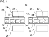
- Figure 1 shows a device 10 for generating compressed air for a motor vehicle.
- the motor vehicle is preferably a commercial vehicle, e.g. B. a truck or a bus.
- the motor vehicle is preferably an electric vehicle or a hybrid vehicle.
- the device 10 has a first compressed air system 12 and a second compressed air system 14. Both compressed air systems 12, 14 are used to supply different consumers with compressed air.
- the first compressed air system 12 has a first air compressor 16, a first compressed air preparation 18, an optional first compressed air reservoir 20 and a first valve device 22.
- the first air compressor 16 is designed to suck in ambient air and to compress it, for. B. in a range around 10 bar.
- the first air compressor 16 has an electric drive for driving a compressor section of the first air compressor 16.
- the first air compressor 16 is preferably connected to a low-voltage direct voltage source for energy supply.
- the first compressed air preparation unit 18 is arranged downstream of the first air compressor 16.
- the first compressed air preparation unit 18 receives compressed air from the first air compressor 16.
- the first compressed air preparation unit 18 can condition the compressed air for storage and / or further use.
- the first compressed air preparation 18 can have an air dryer and / or an air filter.
- the first compressed air reservoir 20 is arranged downstream of the first compressed air preparation 18.
- the first compressed air reservoir 20 can have one or more compressed air tanks. Compressed air can be stored in the first compressed air reservoir 20.
- the first Compressed air reservoir 20 can, for example, have a compressed air tank which is assigned to a front axle service brake circuit, preferably with a volume of 30 l or more.
- the first valve device 22 is arranged downstream of the first compressed air preparation 18 and the first compressed air reservoir 20.
- the first valve device 22 can distribute the compressed air made available by the first compressed air preparation 18 and the first compressed air reservoir 20 to compressed air consumer circuits 24, 26 as desired.
- the first valve device 22 is preferably designed as a two-circuit protection valve.
- the compressed air consumer circuit 24 can preferably be designed as a front axle service brake circuit.
- the compressed air consumer circuit 26 can preferably be designed as a secondary consumer circuit.
- the auxiliary consumer circuit can have pneumatically operated auxiliary consumers of the motor vehicle, for example a driver's cab mounting or a transmission clutch.
- the first compressed air system 12 can also have a first control unit 28, which preferably controls the first air compressor 16 and / or the first valve device 22.
- the first control unit 28 is preferably a sub-control unit of an electronic brake control of the motor vehicle.
- the first compressed air system 12 can include other components if desired.
- the first compressed air system 12 can also have solenoid valves for the secondary consumers of the compressed air consumer circuit 26 and / or compressed air / test connections.
- the first compressed air system 12 can also have at least one component of an electronic air suspension system of a front axle of the motor vehicle.
- the second compressed air system 14 has a second air compressor 30, a second compressed air preparation 32, an optional second compressed air reservoir 34 and a second valve device 36.
- the second air compressor 30 is designed to suck in ambient air and to compress it, for. B. in a range around 10 bar.
- the second air compressor 30 has an electric drive for driving a compressor section of the second air compressor 30.
- the second air compressor 30 is preferably connected to a low-voltage direct voltage source for energy supply.
- the second compressed air preparation 32 is arranged downstream of the second air compressor 30.
- the second compressed air preparation 32 receives compressed air from the second air compressor 30.
- the second compressed air preparation 32 can prepare the compressed air for storage and / or further use.
- the second compressed air preparation 32 can have an air dryer and / or an air filter.
- the second compressed air reservoir 34 is arranged downstream of the second compressed air preparation 32.
- the second compressed air reservoir 34 can have one or more compressed air reservoirs. Compressed air can be stored in the second compressed air reservoir 34.
- the second compressed air reservoir 34 can, for example, have a compressed air tank which is assigned to a rear axle service brake circuit (for a first rear axle), preferably with a volume of 40 l or more.
- the second compressed air reservoir 34 can optionally have a further compressed air tank which, in the case of a double-axle rear axle, is also assigned to the rear axle service brake, preferably with a volume of 30 l or more. It is also possible for the second compressed air reservoir 34 to have a compressed air reservoir for a trailer brake circuit.
- the second valve device 36 is arranged downstream of the second compressed air preparation 32 and the second compressed air reservoir 34.
- the second valve device 36 can distribute the compressed air made available by the second compressed air preparation 32 and the second compressed air reservoir 34 to the compressed air consumer circuits 38, 40 as desired.
- the valve device 36 is preferably designed as a two-circuit protection valve.
- the compressed air consumer circuit 38 can preferably be designed as a rear axle service brake circuit.
- the compressed air consumer circuit 40 can preferably be designed as a (z. B. rear axle) parking brake circuit and / or trailer brake circuit.
- the second compressed air system 14 can furthermore have a second control unit 42, which preferably controls the second air compressor 30 and / or the second valve device 36.
- the second control unit 42 is preferably a sub-control unit of an electronic brake control of the motor vehicle.
- the second compressed air system 14 can include other components if desired.
- the first compressed air system 12 can also have a pressure reducer, which is assigned to the parking brake circuit and / or the trailer brake circuit, and / or compressed air / test connections.
- the first compressed air system 12 can also have at least one Have components of an electronic air suspension system at least one rear axle of the motor vehicle.
- the first compressed air system 12 and the second compressed air system 14 can be preassembled and pre-grouped as modules during production.
- the individual components of the compressed air systems 12, 14 can be functionally connected to one another before the respective compressed air system 12, 14 is installed in the motor vehicle and connected, for example, via central control interfaces (e.g. 24 V).
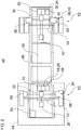
- Figure 2 shows a preferred installation situation for the two compressed air systems 12, 14 in a motor vehicle 44, preferably designed as a utility vehicle.
- the compressed air consumer circuits 24, 26, 38 and 40 are only shown purely schematically.
- the motor vehicle 44 has a vehicle frame 46, which is preferably designed as a ladder frame.
- the vehicle frame 46 can support a driver's cab 48 of the motor vehicle 44, for example.
- the first compressed air system 12 can be arranged in a front region of the motor vehicle 44, preferably a front vehicle 50.
- the second compressed air system 14 can be arranged in a rear area of the motor vehicle 44, preferably in a rear carriage 52.
- the compressed air systems 12, 14 can each be arranged between and at the level of the two parallel main longitudinal members of the vehicle frame 46. However, other arrangements are also conceivable, e.g. B. on the outside of one of the main side members.
- the compressed air consumer circuit 24, designed as a front axle service brake circuit, has, for example, a plurality of front axle brake cylinders 58.
- the front axle brake cylinders 58 can be acted upon with compressed air by the first compressed air system 12 for braking.
- the compressed air consumer circuit 38 designed as a rear axle service brake circuit
- the compressed air consumer circuit 40 designed as a parking brake circuit
- the rear axle brake cylinders 60 can release a parking brake when they are acted upon by compressed air from the second compressed air system 14.
- the parking brake is activated in the unactuated or depressurized state.
- a service brake of the rear axle brake cylinder 60 can be acted upon with compressed air by the second compressed air system 14 for braking.
- the two control units 28, 42 can communicate with one another and / or with a main control unit 54, e.g. B. via a vehicle bus system (e.g. CAN bus).
- the main control unit 54 can be a central control unit of an electronic braking system of the motor vehicle 44.
- the compressed air systems 12, 14 it is possible for the compressed air systems 12, 14 to be fluidically separated from one another. However, it is also possible for the two compressed air systems 12, 14 to be fluidically connected to one another by means of a compressed air connection line 56 (only schematically in FIG Figure 2 shown) are connected or connectable. In the event of a malfunction of one of the compressed air systems 12 or 14, the respective other compressed air system could thus deliver compressed air to the faulty compressed air system.
- the compressed air connection line 56 can, for example, open into a line section of the first compressed air system 12 upstream of the first valve device 22 or be connected to the first valve device 22.
- the compressed air connection line 56 can, for example, open into a line section of the second compressed air system 14 upstream of the second valve device 36 or be connected to the second valve device 36. It is possible for a shut-off valve, a control valve and / or a check valve to be arranged in the compressed air connection line 56.
- the compressed air connection line 56 can be operated bidirectionally, so that compressed air can be conveyed back and forth between the first compressed air system 12 and the second compressed air system 14 as desired. However, it is also possible that the compressed air connection line can only be operated unidirectionally.
- a check valve could be arranged in or on the compressed air connection line 56.
- compressed air could be supplied from the first compressed air system 12 to the compressed air system 14, in particular to the compressed air consumer circuit 40 designed as a parking brake circuit, in order to be able to at least release the parking brake.
- the invention is not restricted to the preferred exemplary embodiments described above. Rather, a large number of variants and modifications are possible which also make use of the inventive concept and therefore fall within the scope of protection.
- the invention also claims protection for the subject matter and the features of the subclaims independently of the claims referred to.
- the individual features of independent claim 1 are disclosed independently of one another.
- the features of the subclaims are also independent of all of them Features of independent claim 1 and for example independently of the features relating to the presence and / or the configuration of the first compressed air system, the second compressed air system, the at least one first compressed air consumer circuit and / or the at least one second compressed air consumer circuit of the independent claim 1 disclosed.
Landscapes
- Engineering & Computer Science (AREA)
- Transportation (AREA)
- Mechanical Engineering (AREA)
- Valves And Accessory Devices For Braking Systems (AREA)
- Fluid-Pressure Circuits (AREA)
Applications Claiming Priority (1)
| Application Number | Priority Date | Filing Date | Title |
|---|---|---|---|
| DE102020115787.8A DE102020115787A1 (de) | 2020-06-16 | 2020-06-16 | Kraftfahrzeug mit Druckluftsystem |
Publications (3)
| Publication Number | Publication Date |
|---|---|
| EP3925840A1 true EP3925840A1 (fr) | 2021-12-22 |
| EP3925840A8 EP3925840A8 (fr) | 2022-02-16 |
| EP3925840B1 EP3925840B1 (fr) | 2023-11-08 |
Family
ID=76098843
Family Applications (1)
| Application Number | Title | Priority Date | Filing Date |
|---|---|---|---|
| EP21175646.5A Active EP3925840B1 (fr) | 2020-06-16 | 2021-05-25 | Véhicule automobile pourvu de système à air comprimé |
Country Status (2)
| Country | Link |
|---|---|
| EP (1) | EP3925840B1 (fr) |
| DE (1) | DE102020115787A1 (fr) |
Citations (5)
| Publication number | Priority date | Publication date | Assignee | Title |
|---|---|---|---|---|
| DE3412979A1 (de) * | 1984-04-06 | 1985-10-24 | Wabco Westinghouse Fahrzeugbremsen GmbH, 3000 Hannover | Drucklufterzeugungseinrichtung mit zwei kreisen mit unterschiedlichen druecken |
| EP0165376A2 (fr) * | 1984-06-22 | 1985-12-27 | WABCO Westinghouse Fahrzeugbremsen GmbH | Système pneumatique à haute pression avec deux circuits à pression différente |
| DE19939200A1 (de) * | 1999-06-22 | 2000-12-28 | Alfmeier Praez Ag | Vorrichtung und Verfahren zur Bereitstellung von Druck in einem Druckspeicher eines Kraftfahrzeuges |
| DE10003869A1 (de) * | 2000-01-28 | 2001-08-16 | Aerzener Maschf Gmbh | Verfahren zum Komprimieren von fluiden Fördermedien |
| EP1396406A1 (fr) * | 2002-09-03 | 2004-03-10 | KNORR-BREMSE SYSTEME FÜR NUTZFAHRZEUGE GmbH | Procédé pour la production d'air comprimé et disposition de compresseurs permettant la mise en oeuvre dudit procédé |
Family Cites Families (3)
| Publication number | Priority date | Publication date | Assignee | Title |
|---|---|---|---|---|
| DE102014207509A1 (de) | 2014-04-17 | 2015-10-22 | Continental Teves Ag & Co. Ohg | Integrierte Luftversorgungseinheit |
| WO2017093532A1 (fr) | 2015-12-03 | 2017-06-08 | Continental Teves Ag & Co. Ohg | Ressort pneumatique comprenant un compresseur d'air intégré |
| DE102017107276A1 (de) | 2017-04-05 | 2018-10-11 | Knorr-Bremse Systeme für Schienenfahrzeuge GmbH | Verfahren und Einrichtung für eine bedarfsgerechte Druckluftversorgung eines Fahrzeuges, insbesondere eines Schienenfahrzeuges |
-
2020
- 2020-06-16 DE DE102020115787.8A patent/DE102020115787A1/de active Pending
-
2021
- 2021-05-25 EP EP21175646.5A patent/EP3925840B1/fr active Active
Patent Citations (5)
| Publication number | Priority date | Publication date | Assignee | Title |
|---|---|---|---|---|
| DE3412979A1 (de) * | 1984-04-06 | 1985-10-24 | Wabco Westinghouse Fahrzeugbremsen GmbH, 3000 Hannover | Drucklufterzeugungseinrichtung mit zwei kreisen mit unterschiedlichen druecken |
| EP0165376A2 (fr) * | 1984-06-22 | 1985-12-27 | WABCO Westinghouse Fahrzeugbremsen GmbH | Système pneumatique à haute pression avec deux circuits à pression différente |
| DE19939200A1 (de) * | 1999-06-22 | 2000-12-28 | Alfmeier Praez Ag | Vorrichtung und Verfahren zur Bereitstellung von Druck in einem Druckspeicher eines Kraftfahrzeuges |
| DE10003869A1 (de) * | 2000-01-28 | 2001-08-16 | Aerzener Maschf Gmbh | Verfahren zum Komprimieren von fluiden Fördermedien |
| EP1396406A1 (fr) * | 2002-09-03 | 2004-03-10 | KNORR-BREMSE SYSTEME FÜR NUTZFAHRZEUGE GmbH | Procédé pour la production d'air comprimé et disposition de compresseurs permettant la mise en oeuvre dudit procédé |
Also Published As
| Publication number | Publication date |
|---|---|
| EP3925840B1 (fr) | 2023-11-08 |
| EP3925840A8 (fr) | 2022-02-16 |
| DE102020115787A1 (de) | 2021-12-16 |
Similar Documents
| Publication | Publication Date | Title |
|---|---|---|
| EP1502778B2 (fr) | Système de traitement de l'air comprimé pour véhicules | |
| EP2942249B1 (fr) | Système de frein entraîné par fluide sous pression pour un véhicule automobile et véhicule automobile associé | |
| EP1464557B2 (fr) | Dispositif de traitement d'air comprimé | |
| DE60208804T2 (de) | Druckluftverarbeitungsvorrichtung | |
| EP1785325B2 (fr) | Dispositif de réglage d'un système de freinage à air comprimé pour un véhicule | |
| EP1464556B1 (fr) | Système de traitement de l'air comprimé pour véhicules | |
| EP2570316B1 (fr) | Dispositif de préparation d'air comprimé pour un véhicule utilitaire | |
| DE102012007119A1 (de) | Verfahren zum Betrieb eines Kraftfahrzeugs während und/oder nach einer Kollision | |
| DE60206176T2 (de) | Gerät für druckluftbehandlung, für industriefahrzeug | |
| EP1731394B1 (fr) | Installation d'alimentation en air comprimé | |
| EP1741578B1 (fr) | Dispositif de commande de système de suspension pneumatique d'un véhicule | |
| EP1508488B1 (fr) | Installation de production d'air comprimé pour véhicule et méthode pour le faire fonctionner | |
| EP3616771A1 (fr) | Module à air comprimé pour un véhicule utilitaire et son procédé d'essai | |
| DE102017221859A1 (de) | Flüssigkeitdrucksteuergerät des Bremssystems für Fahrzeuge mit Sattel und Bremssystem für Fahrzeuge mit Sattel | |
| EP3925840B1 (fr) | Véhicule automobile pourvu de système à air comprimé | |
| DE19537622B4 (de) | Einrichtung für ein Schienenfahrzeug mit durchgehender Hauptluftleitung und Federspeicher-Feststellbremse | |
| EP1764276B1 (fr) | Système de freinage pneumatique pour véhicule automobile | |
| EP3829946B1 (fr) | Frein à main électropneumatique (ebh) avec tcv partiellement decouplé (type d'activation européen) | |
| DE102007038288A1 (de) | Hilfsbremsvorrichtung für Nutzfahrzeuge | |
| EP3335917B1 (fr) | Dispositif d'amortissement pneumatique pour un véhicule automobile | |
| EP2371644B1 (fr) | Installation à air comprimé | |
| DE102022117696B3 (de) | Anordnung und Verfahren zum Hilfslösen einer Bremse eines Schienenfahrzeugs sowie Schienenfahrzeug | |
| DE19848995A1 (de) | Bremssystem für ein Schienenfahrzeug | |
| DE102020118947A1 (de) | Verfahren zum Betrieb eines Nutzfahrzeugs mit einer Luftfederungsanlage, Luftfederungsanlage, Nutzfahrzeug und Nutzfahrzeugsystem | |
| DE102014113062B4 (de) | Reifendruckregulierungsvorrichtung mit Boostereinrichtung, insbesondere für einen Nutzfahrzeuganhänger |
Legal Events
| Date | Code | Title | Description |
|---|---|---|---|
| PUAI | Public reference made under article 153(3) epc to a published international application that has entered the european phase |
Free format text: ORIGINAL CODE: 0009012 |
|
| STAA | Information on the status of an ep patent application or granted ep patent |
Free format text: STATUS: THE APPLICATION HAS BEEN PUBLISHED |
|
| AK | Designated contracting states |
Kind code of ref document: A1 Designated state(s): AL AT BE BG CH CY CZ DE DK EE ES FI FR GB GR HR HU IE IS IT LI LT LU LV MC MK MT NL NO PL PT RO RS SE SI SK SM TR |
|
| B565 | Issuance of search results under rule 164(2) epc |
Effective date: 20211115 |
|
| RAP3 | Party data changed (applicant data changed or rights of an application transferred) |
Owner name: MAN TRUCK & BUS SE |
|
| STAA | Information on the status of an ep patent application or granted ep patent |
Free format text: STATUS: REQUEST FOR EXAMINATION WAS MADE |
|
| 17P | Request for examination filed |
Effective date: 20220614 |
|
| RBV | Designated contracting states (corrected) |
Designated state(s): AL AT BE BG CH CY CZ DE DK EE ES FI FR GB GR HR HU IE IS IT LI LT LU LV MC MK MT NL NO PL PT RO RS SE SI SK SM TR |
|
| RIC1 | Information provided on ipc code assigned before grant |
Ipc: B60T 13/26 20060101ALI20230413BHEP Ipc: B60T 17/22 20060101ALI20230413BHEP Ipc: B60T 17/04 20060101ALI20230413BHEP Ipc: B60T 17/00 20060101AFI20230413BHEP |
|
| GRAP | Despatch of communication of intention to grant a patent |
Free format text: ORIGINAL CODE: EPIDOSNIGR1 |
|
| STAA | Information on the status of an ep patent application or granted ep patent |
Free format text: STATUS: GRANT OF PATENT IS INTENDED |
|
| INTG | Intention to grant announced |
Effective date: 20230621 |
|
| GRAS | Grant fee paid |
Free format text: ORIGINAL CODE: EPIDOSNIGR3 |
|
| GRAA | (expected) grant |
Free format text: ORIGINAL CODE: 0009210 |
|
| STAA | Information on the status of an ep patent application or granted ep patent |
Free format text: STATUS: THE PATENT HAS BEEN GRANTED |
|
| AK | Designated contracting states |
Kind code of ref document: B1 Designated state(s): AL AT BE BG CH CY CZ DE DK EE ES FI FR GB GR HR HU IE IS IT LI LT LU LV MC MK MT NL NO PL PT RO RS SE SI SK SM TR |
|
| REG | Reference to a national code |
Ref country code: GB Ref legal event code: FG4D Free format text: NOT ENGLISH |
|
| REG | Reference to a national code |
Ref country code: CH Ref legal event code: EP |
|
| REG | Reference to a national code |
Ref country code: DE Ref legal event code: R096 Ref document number: 502021001899 Country of ref document: DE |
|
| REG | Reference to a national code |
Ref country code: IE Ref legal event code: FG4D Free format text: LANGUAGE OF EP DOCUMENT: GERMAN |
|
| REG | Reference to a national code |
Ref country code: SE Ref legal event code: TRGR |
|
| REG | Reference to a national code |
Ref country code: NL Ref legal event code: FP |
|
| REG | Reference to a national code |
Ref country code: LT Ref legal event code: MG9D |
|
| PG25 | Lapsed in a contracting state [announced via postgrant information from national office to epo] |
Ref country code: GR Free format text: LAPSE BECAUSE OF FAILURE TO SUBMIT A TRANSLATION OF THE DESCRIPTION OR TO PAY THE FEE WITHIN THE PRESCRIBED TIME-LIMIT Effective date: 20240209 |
|
| PG25 | Lapsed in a contracting state [announced via postgrant information from national office to epo] |
Ref country code: IS Free format text: LAPSE BECAUSE OF FAILURE TO SUBMIT A TRANSLATION OF THE DESCRIPTION OR TO PAY THE FEE WITHIN THE PRESCRIBED TIME-LIMIT Effective date: 20240308 |
|
| PG25 | Lapsed in a contracting state [announced via postgrant information from national office to epo] |
Ref country code: LT Free format text: LAPSE BECAUSE OF FAILURE TO SUBMIT A TRANSLATION OF THE DESCRIPTION OR TO PAY THE FEE WITHIN THE PRESCRIBED TIME-LIMIT Effective date: 20231108 |
|
| PG25 | Lapsed in a contracting state [announced via postgrant information from national office to epo] |
Ref country code: ES Free format text: LAPSE BECAUSE OF FAILURE TO SUBMIT A TRANSLATION OF THE DESCRIPTION OR TO PAY THE FEE WITHIN THE PRESCRIBED TIME-LIMIT Effective date: 20231108 |
|
| PG25 | Lapsed in a contracting state [announced via postgrant information from national office to epo] |
Ref country code: LT Free format text: LAPSE BECAUSE OF FAILURE TO SUBMIT A TRANSLATION OF THE DESCRIPTION OR TO PAY THE FEE WITHIN THE PRESCRIBED TIME-LIMIT Effective date: 20231108 Ref country code: IS Free format text: LAPSE BECAUSE OF FAILURE TO SUBMIT A TRANSLATION OF THE DESCRIPTION OR TO PAY THE FEE WITHIN THE PRESCRIBED TIME-LIMIT Effective date: 20240308 Ref country code: GR Free format text: LAPSE BECAUSE OF FAILURE TO SUBMIT A TRANSLATION OF THE DESCRIPTION OR TO PAY THE FEE WITHIN THE PRESCRIBED TIME-LIMIT Effective date: 20240209 Ref country code: ES Free format text: LAPSE BECAUSE OF FAILURE TO SUBMIT A TRANSLATION OF THE DESCRIPTION OR TO PAY THE FEE WITHIN THE PRESCRIBED TIME-LIMIT Effective date: 20231108 Ref country code: BG Free format text: LAPSE BECAUSE OF FAILURE TO SUBMIT A TRANSLATION OF THE DESCRIPTION OR TO PAY THE FEE WITHIN THE PRESCRIBED TIME-LIMIT Effective date: 20240208 Ref country code: PT Free format text: LAPSE BECAUSE OF FAILURE TO SUBMIT A TRANSLATION OF THE DESCRIPTION OR TO PAY THE FEE WITHIN THE PRESCRIBED TIME-LIMIT Effective date: 20240308 |