EP2942249B1 - Système de frein entraîné par fluide sous pression pour un véhicule automobile et véhicule automobile associé - Google Patents
Système de frein entraîné par fluide sous pression pour un véhicule automobile et véhicule automobile associé Download PDFInfo
- Publication number
- EP2942249B1 EP2942249B1 EP15001137.7A EP15001137A EP2942249B1 EP 2942249 B1 EP2942249 B1 EP 2942249B1 EP 15001137 A EP15001137 A EP 15001137A EP 2942249 B1 EP2942249 B1 EP 2942249B1
- Authority
- EP
- European Patent Office
- Prior art keywords
- brake
- parking brake
- module
- parking
- brake system
- Prior art date
- Legal status (The legal status is an assumption and is not a legal conclusion. Google has not performed a legal analysis and makes no representation as to the accuracy of the status listed.)
- Active
Links
- 230000004913 activation Effects 0.000 claims 5
- 230000000694 effects Effects 0.000 description 6
- 230000005540 biological transmission Effects 0.000 description 2
- 230000001276 controlling effect Effects 0.000 description 2
- 230000009365 direct transmission Effects 0.000 description 2
- 230000005611 electricity Effects 0.000 description 2
- 239000012528 membrane Substances 0.000 description 2
- 230000006855 networking Effects 0.000 description 2
- 230000001105 regulatory effect Effects 0.000 description 2
- 239000013589 supplement Substances 0.000 description 2
- 238000013022 venting Methods 0.000 description 2
- 230000008878 coupling Effects 0.000 description 1
- 238000010168 coupling process Methods 0.000 description 1
- 238000005859 coupling reaction Methods 0.000 description 1
- 230000007547 defect Effects 0.000 description 1
- 230000008030 elimination Effects 0.000 description 1
- 238000003379 elimination reaction Methods 0.000 description 1
- 238000009434 installation Methods 0.000 description 1
- 230000007257 malfunction Effects 0.000 description 1
- 238000000034 method Methods 0.000 description 1
Images

Classifications
-
- B—PERFORMING OPERATIONS; TRANSPORTING
- B60—VEHICLES IN GENERAL
- B60T—VEHICLE BRAKE CONTROL SYSTEMS OR PARTS THEREOF; BRAKE CONTROL SYSTEMS OR PARTS THEREOF, IN GENERAL; ARRANGEMENT OF BRAKING ELEMENTS ON VEHICLES IN GENERAL; PORTABLE DEVICES FOR PREVENTING UNWANTED MOVEMENT OF VEHICLES; VEHICLE MODIFICATIONS TO FACILITATE COOLING OF BRAKES
- B60T13/00—Transmitting braking action from initiating means to ultimate brake actuator with power assistance or drive; Brake systems incorporating such transmitting means, e.g. air-pressure brake systems
- B60T13/10—Transmitting braking action from initiating means to ultimate brake actuator with power assistance or drive; Brake systems incorporating such transmitting means, e.g. air-pressure brake systems with fluid assistance, drive, or release
- B60T13/66—Electrical control in fluid-pressure brake systems
- B60T13/68—Electrical control in fluid-pressure brake systems by electrically-controlled valves
- B60T13/683—Electrical control in fluid-pressure brake systems by electrically-controlled valves in pneumatic systems or parts thereof
-
- B—PERFORMING OPERATIONS; TRANSPORTING
- B60—VEHICLES IN GENERAL
- B60T—VEHICLE BRAKE CONTROL SYSTEMS OR PARTS THEREOF; BRAKE CONTROL SYSTEMS OR PARTS THEREOF, IN GENERAL; ARRANGEMENT OF BRAKING ELEMENTS ON VEHICLES IN GENERAL; PORTABLE DEVICES FOR PREVENTING UNWANTED MOVEMENT OF VEHICLES; VEHICLE MODIFICATIONS TO FACILITATE COOLING OF BRAKES
- B60T13/00—Transmitting braking action from initiating means to ultimate brake actuator with power assistance or drive; Brake systems incorporating such transmitting means, e.g. air-pressure brake systems
- B60T13/10—Transmitting braking action from initiating means to ultimate brake actuator with power assistance or drive; Brake systems incorporating such transmitting means, e.g. air-pressure brake systems with fluid assistance, drive, or release
- B60T13/24—Transmitting braking action from initiating means to ultimate brake actuator with power assistance or drive; Brake systems incorporating such transmitting means, e.g. air-pressure brake systems with fluid assistance, drive, or release the fluid being gaseous
- B60T13/26—Compressed-air systems
- B60T13/261—Compressed-air systems systems with both indirect application and application by springs or weights and released by compressed air
-
- B—PERFORMING OPERATIONS; TRANSPORTING
- B60—VEHICLES IN GENERAL
- B60T—VEHICLE BRAKE CONTROL SYSTEMS OR PARTS THEREOF; BRAKE CONTROL SYSTEMS OR PARTS THEREOF, IN GENERAL; ARRANGEMENT OF BRAKING ELEMENTS ON VEHICLES IN GENERAL; PORTABLE DEVICES FOR PREVENTING UNWANTED MOVEMENT OF VEHICLES; VEHICLE MODIFICATIONS TO FACILITATE COOLING OF BRAKES
- B60T13/00—Transmitting braking action from initiating means to ultimate brake actuator with power assistance or drive; Brake systems incorporating such transmitting means, e.g. air-pressure brake systems
- B60T13/10—Transmitting braking action from initiating means to ultimate brake actuator with power assistance or drive; Brake systems incorporating such transmitting means, e.g. air-pressure brake systems with fluid assistance, drive, or release
- B60T13/24—Transmitting braking action from initiating means to ultimate brake actuator with power assistance or drive; Brake systems incorporating such transmitting means, e.g. air-pressure brake systems with fluid assistance, drive, or release the fluid being gaseous
- B60T13/26—Compressed-air systems
- B60T13/38—Brakes applied by springs or weights and released by compressed air
- B60T13/385—Control arrangements therefor
-
- B—PERFORMING OPERATIONS; TRANSPORTING
- B60—VEHICLES IN GENERAL
- B60T—VEHICLE BRAKE CONTROL SYSTEMS OR PARTS THEREOF; BRAKE CONTROL SYSTEMS OR PARTS THEREOF, IN GENERAL; ARRANGEMENT OF BRAKING ELEMENTS ON VEHICLES IN GENERAL; PORTABLE DEVICES FOR PREVENTING UNWANTED MOVEMENT OF VEHICLES; VEHICLE MODIFICATIONS TO FACILITATE COOLING OF BRAKES
- B60T13/00—Transmitting braking action from initiating means to ultimate brake actuator with power assistance or drive; Brake systems incorporating such transmitting means, e.g. air-pressure brake systems
- B60T13/10—Transmitting braking action from initiating means to ultimate brake actuator with power assistance or drive; Brake systems incorporating such transmitting means, e.g. air-pressure brake systems with fluid assistance, drive, or release
- B60T13/66—Electrical control in fluid-pressure brake systems
- B60T13/662—Electrical control in fluid-pressure brake systems characterised by specified functions of the control system components
Definitions
- the invention relates to a pressure medium-operated brake system for a motor vehicle, in particular a commercial vehicle, with a service brake device and a parking brake device according to the preamble of claim 1 and a motor vehicle with such a brake system.
- a brake system in which several pneumatically operated service brake circuits are provided.
- a first service brake circuit is provided for the wheels on the front axle and a second service brake circuit for the wheels on the rear axle.
- the brake cylinders used for braking are actuated pneumatically, the pressure required for this being provided by a compressed air reservoir assigned to the respective brake circuit.
- the brake pressure provided is controlled by means of appropriate electro-pneumatic brake control modules.
- EP 2 108 554 A1 discloses a method for operating a brake system of a commercial vehicle comprising a parking brake with parking brake actuators and a service brake, the parking brake supporting braking of the utility vehicle in the event of a defect in the service brake.
- the braking forces to be applied by the parking brake actuators of the parking brake are determined via an ABS control loop and that the parking brake actuators are actuated in accordance with the determined braking forces to be applied.
- Electronic brake systems are usually designed such that the brake control modules u. a. receive electrical signals from a brake value transmitter, which is used to detect the braking request of the driver of the motor vehicle. These electrical signals thus correspond to a braking value requirement specified by the driver and are evaluated by the vehicle electronics. Depending on other sizes, e.g. Loading, the braking force distribution on the axles of the motor vehicle is determined and the brake control modules for the front and rear axles are controlled accordingly.
- a generic brake system has a parking brake device.
- the wheels of at least one rear axle are preferably designed with mostly combined service and spring brake cylinders.
- a spring-loaded spring applies the brake to keep the motor vehicle secure even when depressurized.
- the spring-loaded part of the parking brake device is ventilated during driving, so that the spring-loaded spring no longer applies the brake.
- the motor vehicle is braked by the service brake via the service brake cylinders.
- Redundancy of the braking system can be designed with one or two circuits. With single-circuit redundancy, only one of two independently operating brake circuits is designed redundantly, which is usually the front-axle brake circuit, and with double-circuit redundancy, however, both brake circuits, namely the front-axle brake circuit and the rear-axle brake circuit, are designed redundantly. However, since the rear axle has a constantly changing load / empty ratio, which essentially depends on the payload, it is difficult to design the redundancy on the rear axle brake circuit.
- the invention has for its object to improve the functioning of electronically controlled braking systems of the type mentioned, in particular to increase the reliability in systems with single-circuit redundancy, in order to make the braking system easier and cheaper by the single-circuit redundancy.
- the invention solves this problem with the features of a pressure medium-operated brake system according to claim 1 and with a motor vehicle according to claim 13.
- the pressure medium-operated brake system according to the invention for a motor vehicle comprises a service brake device and a parking brake device, the service brake device being provided a service brake function of the motor vehicle while driving and the parking brake device is used to lock the motor vehicle.
- the parking brake device has a parking brake module and an electrical actuating device coupled to the parking brake module, which is usually arranged as a manual actuation unit in the driver's cab of the motor vehicle.
- the parking brake module a large number or all components of the parking brake device, in particular valve devices, relay valve and control electronics, are usually combined in a single assembly in order to enable the parking brake function of the parking brake device.
- the parking brake module is also referred to as the parking brake module if the other components of the parking brake device are arranged separately.
- the parking brake module it is possible for the parking brake module to be viewed only as a section on a printed circuit board, the parking brake module being able to be arranged on a common printed circuit board with other control electronics of further modules of the electronic braking system, in order to reduce the effort involved in laying electrical and possibly pneumatic ones Reduce lines and assembly costs.
- the service brake device has a brake value transmitter for generating at least one electrical brake request signal, the electrical brake request signal being generated from the driver's pedal actuation.
- the brake value transmitter in addition to the at least one electrical brake request signal from the driver's pedal actuation, corresponding pneumatic pressures for ventilating and venting the brake cylinders can be generated.
- the brake system according to the invention is characterized by at least one data line with which the brake value transmitter is connected directly or indirectly to the parking brake module for establishing a data connection. Via this data line, the brake request signal generated by the brake value transmitter is arranged in the parking brake module or in the parking brake module Control electronics of the parking brake device directly or indirectly.
- the braking effect on the rear axle in the event of a failure of individual components, signal lines and / or supply lines can advantageously not only be ensured, but can also be conveniently controlled for the driver by actuating the brake pedal.
- the parking brake device thus creates redundancy for the service brake circuits, in particular the rear-axle brake circuit, which does not have to be manually operated by the driver as usual.
- the transmitted brake request signal advantageously enables the driver to brake the motor vehicle using the brake pedal even if the service brake device has failed, even though the motor vehicle is then braked via the parking brake device.
- the data line between the brake value transmitter and the parking brake module is designed as a LIN bus (Local Interconnect Network) or has a LIN bus.
- a LIN bus is understood to mean a simple serial bus system for networking intelligent sensors and actuators within the motor vehicle, which advantageously enables simple data transmission at low cost.
- the data line between the brake value transmitter and the parking brake module is designed as a CAN bus (Controller Area Network) or has a CAN bus.
- a CAN bus is understood to mean a serial bus system for networking control devices and sensor units within the motor vehicle, which advantageously has a higher bandwidth than the LIN bus.
- the use of a CAN bus has established itself as the standard in automotive engineering and is therefore advantageous.
- PWM signals pulse-width-modulated signal
- PWM signals can be easily generated and transmitted via any electrical line.
- the brake value transmitter and the electrical actuating device of the parking brake device are each directly connected to the parking brake module for establishing a respective data connection.
- the respective data connections can be designed differently.
- the data connection between the brake value transmitter and the parking brake module advantageously enables the redundancy according to the invention within the electronically controlled brake system.
- the brake value transmitter and the parking brake module are each connected directly to the electrical actuating device of the parking brake device for establishing a data connection.
- the respective data connections can be designed differently.
- the data connection between the brake value transmitter and the electric actuating device of the parking brake device advantageously supplements the existing data connection between the electric actuating device of the parking brake device and the parking brake module, so that only a short, inexpensive signal line, in particular within, is implemented for the redundancy according to the invention within the electronically controlled braking system the console from the brake pedal to the manual control device is necessary. This advantageously saves costs and assembly effort.
- the electrical actuating device of the parking brake device and the parking brake module are each connected directly to the brake value transmitter for establishing a data connection.
- the respective data connections can be designed differently, so that, for example, a data line is designed as a LIN bus and a data line as a CAN bus.
- a data line is designed as a LIN bus and a data line as a CAN bus.
- the brake value transmitter, the parking brake module and the electrical actuating device of the parking brake device are each directly connected to one another for establishing a data connection.
- the respective data connections can be designed differently.
- the data connection between the brake value transmitter and the electrical actuating device of the parking brake device advantageously supplements the data connection between the electrical actuating device of the parking brake device and the parking brake module in order to establish the redundancy according to the invention within the electronically controlled braking system.
- the data connection between the brake value transmitter and the parking brake module advantageously enables additional redundancy within the electronically controlled brake system.
- the parking brake device has at least one service and spring brake cylinder.
- Such combined service and spring-loaded brake cylinders are usually used on the rear axle and have a membrane cylinder for the service brake and a spring-loaded cylinder for the parking brake. Both brake cylinders can be actuated independently of one another, braking being achieved if pressure is applied to the service brake cylinder or if there is a pressure drop on the spring brake cylinder. Braking of the motor vehicle is thus possible even in the absence of compressed air.
- electromechanical parking brake for locking the motor vehicle is also possible.
- the electromechanical parking brake can also be operated via a parking brake module control with appropriate control electronics by the brake value transmitter or the electrical actuating device of the parking brake device.
- the brake system in addition to a first energy supply, has at least one further energy supply that is independent of the first energy supply.
- the first energy supply comprises a main battery, in particular a main motor vehicle battery, with which the electrical actuating device of the parking brake device, the parking brake module, the brake value transmitter and a central module of the brake system are essentially supplied with electricity.
- the further energy supply is provided by a safety battery, in particular a motor vehicle battery.
- a safety battery in particular a motor vehicle battery.
- this essentially serves to supply the electrical actuation device of the parking brake device, the parking brake module, the brake value transmitter and the central module of the braking system, as well as the electrical supply to the wheel modules on the front axle.
- the additional connections for the electrical supply of the wheel modules on the front axle advantageously provide additional fail-safe protection compared to the main battery.
- the brake value transmitter is designed in such a way that it only provides electrical brake request signals.
- the purely pneumatic redundancy is eliminated.
- the elimination of pneumatic redundancy via pneumatic lines on the brake value transmitter advantageously saves on pipework and thus saves costs and effort during installation.
- the brake value transmitter is designed in such a way that, in addition to the electrical brake request signals, pneumatic brake request signals are provided exclusively for the front axle.
- pneumatic brake request signals are provided exclusively for the front axle.
- only one brake circuit is designed redundantly, which is usually the front axle brake circuit.
- the braking effect must be ensured even if the service brake fails.
- the braking effect can advantageously also be ensured on the rear axle in the event of failure of individual components, signal lines and / or supply lines with a single-circuit redundancy of the braking system.
- the parking brake module or the control unit of the parking brake module is arranged in a control unit, the control unit comprising, in addition to a control function of the parking brake module, further control functions or sensor functions, in particular the control functions of a rear axle modulator and / or the sensor functions of a vehicle dynamics sensor module.
- control functions of the individual modules contained in the control unit are preferably carried out by at least two different processors, so that additional redundancy is created.
- the processors are preferably operable independently of one another, so that in the event of a fault in one processor there is no influence on the processor that is not faulty.
- the invention achieves the above-mentioned object with a motor vehicle, in particular a commercial vehicle, which has a braking system according to the invention.
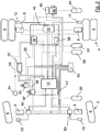
- Fig. 1 shows a schematic representation of a pressure medium-operated brake system, in particular a compressed air-operated brake system.
- brake systems are used, for example, in commercial vehicles, in particular trucks and buses.
- the electrically controlled brake system shown only shows a few selected components.
- the motor vehicle shown here has a front axle 2 and a rear axle 4.
- the invention is not limited to two-axle vehicles. Rather, motor vehicles with more than two axles, in particular several rear axles and / or several front axles, can also be used.
- a motor vehicle is understood to mean a tractor vehicle or a motor vehicle without a train function, for example a bus.
- the motor vehicle has wheels 6 on the front axle 2 and on the rear axle 4, which are each provided with brake cylinders 8 for individual braking.
- the brake cylinders 8 are formed at least on the rear axle 4 as a combined service and spring brake cylinder.
- the service brake part is provided with a membrane which can be acted upon by compressed air and is pneumatically connected to the service brake system.
- the spring-loaded part is pneumatically separated from the service brake part and can be supplied with compressed air via a separate compressed air line.
- Speed sensing means 10 are respectively arranged on the wheels 6 in order to determine the respective wheel rotational speed.
- the speed sensing means 10 are connected via a front axle modulator 12 via electrical lines to a central module 14 of the electrically controlled brake system.
- ABS valves 16 Antilock Braking System
- for controlling the brake pressure of the brake cylinders 8 are connected to the front axle modulator 12 via compressed air lines and to the central module 14 of the brake system via electrical lines.
- the brake system also has a brake value sensor 18 'which detects a braking request from the driver.
- the brake value transmitter 18 ' comprises a pneumatic part and an electrical part.
- the pneumatic part is supplied with compressed air from a first compressed air reservoir 20.
- a pneumatic manipulated variable is generated by the brake value transmitter 18 ′, which is passed on to the brake cylinders 8 of the front axle 2 via compressed air lines.
- the pneumatic signals are only required in the event of redundancy, they are no longer taken into account in normal braking operation.
- the electrical part of the brake value transmitter 18 has an electrical sensor which detects the mechanical actuation of the brake pedal and generates a signal representing this actuation. This electrical signal is used to control the braking system on an electrical basis and is transmitted to the central module 14 as an electrical braking request signal.
- the speed sensor 10 transfers the wheel speed of the individual wheels 6 of the rear axle 4 to the rear axle modulator 22 via electrical lines .
- the rear axle modulator 22 is connected to the central module 14 via an electrical line and via a data line and receives an electrical brake request signal from the brake value transmitter 18 ′ from the central module 14.
- the brake pressure in the brake cylinders 8 of the rear wheels 6 is controlled via valves arranged in the rear axle modulator 22.
- the rear air modulator 22 takes the compressed air required for this purpose from a second compressed air reservoir 24.
- the brake cylinders 8 of the rear axle 4 are preferably designed as combined service and spring brake cylinders, in order to provide a parking brake function in addition to the service brake.
- the spring-loaded part of the brake cylinder 8 is connected to a parking brake module 26 via pneumatic compressed air lines.
- the parking brake module 26 has an electronic control device which u. a. is used to adjust the parking brake.
- the valves of the parking brake module 26 are actuated in such a way that the brake pressure which arises in the pressure line approximately corresponds to the brake pressure setpoint. A braking effect is then achieved via spring brake cylinders.
- the invention is not limited to a parking brake module 26 with all components of the parking brake device. Rather, the electrical control device for performing the parking brake function in connection with the invention can also be referred to as a parking brake module 26.
- the rear axle modulator 22 is also connected to the central module 14 via a data line.
- the front axle modulator 12 is also connected to the central module 14 via a data line.
- the parking brake module 26 is connected via a data line 28 to an electrical actuating device 30 of the parking brake device, wherein a PWM signal can be transmitted via the data line 28 or the data line 28 is designed entirely or partially as a CAN bus, or preferably entirely or partially as an inexpensive LIN -Bus is trained.
- the parking brake module 26 and the electrical actuator 30 are powered by a power supply device, e.g. a vehicle battery as a first power supply 32, supplied with electricity via an electrical line.
- a power supply device e.g. a vehicle battery as a first power supply 32, supplied with electricity via an electrical line.
- This power supply device 32 also supplies the central module 14 of the braking system with power via a further electrical line.
- the parking brake module 26 is connected to the central module 14 via a data line 33, in particular a vehicle data bus or CAN bus.
- a steering angle sensor 34 is also arranged on this data line 33, the data of which is transferred via the data line 33 to the central module 14 of the braking system.
- the steering angle sensor 34 is e.g. attached to the steering column and passes on information about the driver's steering movement to the electronics of the brake system.
- the parking brake module 26 is connected via a compressed air line to a third compressed air reservoir 36 for supplying compressed air.
- the brake system shown furthermore has a driving dynamics sensor module 38, in particular an ESC module (Electronic Stability Control), wherein the sensor function of the ESC module enables corrective intervention in the engine and brake control in stability-critical driving situations and advantageously a tilting within the limits of physical limits , Skidding, turning and / or buckling of the motor vehicle can be prevented.
- ESC module Electronic Stability Control
- the driving dynamics sensor module 38, the parking brake module 26 and the rear axle modulator 22 can be arranged in a common control device 40, which is indicated by a dashed frame in FIG Fig. 1 is shown.
- Arranging the individual modules or the individual control functions of the respective modules in a common control device 40 has the advantage that less Space and less electrical and possibly pneumatic lines are required. At the same time, the assembly effort and the assembly costs are reduced.
- the motor vehicle described so far is also suitable for coupling a trailer vehicle.
- the brake system has a trailer control valve 42, which is used to control the brake pressure of a coupled trailer vehicle.
- the trailer control valve 42 is connected to a fourth compressed air reservoir 44 via a compressed air line for supplying compressed air.
- the trailer control valve 42 passes on the compressed air of the compressed air reservoir 44 in accordance with electrical and / or pneumatic control signals to the braking system of the trailer vehicle.
- the compressed air storage containers 20, 24, 36 and 44 are supplied via a compressed air supply system, not shown here, e.g. a compressor driven by the motor vehicle, filled with compressed air.
- a compressed air supply system not shown here, e.g. a compressor driven by the motor vehicle, filled with compressed air.
- an electrical plug connection 46 is provided for the power supply and for the transmission of data signals for the trailer vehicle.
- a pressure for the brake cylinders 8 is determined by means of an electrical brake request signal via the central module 14 and regulated by the front axle modulator 12 and the rear axle modulator 22.
- redundancy is to be established according to the invention via the parking brake, in which the driver can brake the motor vehicle as usual using the brake pedal.
- the brake value transmitter 18 'and the electrical actuating device 30 of the parking brake have a data line 48 for establishing a data connection.
- the brake request signal from the brake value transmitter 18 ' is transferred directly to the electrical actuating device 30 of the parking brake, which acts as a relay, in order to control the brake cylinders 8 on the rear axle via the parking brake module 26 directly via the data line 28 in accordance with the driver's braking request.
- the data line 48 is preferably an inexpensive LIN bus. However, it is also conceivable to use a CAN bus or a PWM signal, as well as to use any network structure that is suitable for transmitting the brake request signal. Furthermore, different data lines can be combined with one another.
- the arrangement of the data line 48 in the driver's cabin between the brake pedal of the brake value transmitter 18 'and the manual actuation unit of the electrical actuation device 30 saves costs and assembly effort.
- the invention is not limited to such an arrangement for establishing a data connection between the brake value transmitter 18 ′ and the parking brake module 26. Rather, according to an alternative embodiment of the invention, there is a direct, but not shown, data connection between the brake value transmitter 18 'and the parking brake module 26 via an in Fig. 1 Data line, not shown, is provided.
- the data connection according to the invention between the brake value transmitter 18 'and the parking brake module 26 enables according to the legal requirements a redundancy on the rear axle 4 via the parking brake device, wherein the pneumatic redundancy on the rear axle 4 can advantageously be saved.
- Fig. 2 shows a schematic representation of a brake system without pneumatic redundancy.
- the second exemplary embodiment is essentially the same as the first exemplary embodiment.
- the same reference numerals designate the same parts.
- the in Fig. 2 shown brake value transmitter 18 "has in addition to a power supply line to the first power supply 32 and a power supply line to the second power supply 52 only data lines with which the electrical braking request signal, which corresponds to the driver's braking request to the central module 14 and to wheel modules 50 on the front axle 2 of the Motor vehicle is transmitted, wherein the wheel modules 50 control the brake cylinders 8 of the wheels 6 in accordance with the braking request signal.
- the brake system can have a central brake unit 14 ', which includes the central module 14 of the brake system and the brake value transmitter 18'.
- This power supply device 52 enables the electronically controlled braking system to operate even if the first energy supply 32 fails, which provides additional reliability of the braking system since the other energy supply can maintain all braking functions of the electrically controlled braking system.
- the data lines 48 and 28 can be designed differently, but preferably as an inexpensive LIN bus.
- a data line (not shown) directly between the brake value transmitter 18 ′′ and the parking brake module 26 or the common control device 40 for transmitting the brake request signal is also conceivable.
- the brake value transmitter 18 ′′ can transmit a corresponding brake request signal to the parking brake device, so that the rear axle 4 is braked with the aid of the spring-loaded brake cylinder Main battery 32 of the motor vehicle is interrupted.
- a pressure-medium-operated brake system do not represent any restriction. Individual parts of the brake system can be arranged or distributed in any way.
Claims (13)
- Système de freinage entraîné par fluide sous pression pour un véhicule automobile, en particulier un véhicule utilitaire, comprenant un dispositif de frein de service et un dispositif de frein de stationnement, le dispositif de frein de stationnement présentant un module de frein de stationnement (26) et un dispositif d'actionnement électrique (30) couplé au module de frein de stationnement (26), et dans lequel le dispositif de frein de service présente un générateur de valeur de freinage (18', 18") pour générer au moins un signal de demande de freinage électrique,
caractérisé en ce que
le générateur de valeur de freinage (18', 18") est relié indirectement ou directement au moyen d'au moins une ligne de données au module de frein de stationnement (26) pour établir une liaison de données, et
le signal de demande de freinage est transmis sur cette ligne de données au module de frein de stationnement (26) afin de piloter ainsi des cylindres de frein (8) selon le freinage souhaité du conducteur. - Système de freinage selon la revendication 1, caractérisé en ce que la ligne de données est ou présente un bus LIN.
- Système de freinage selon la revendication 1 ou 2, caractérisé en ce que la ligne de données est ou présente un bus CAN.
- Système de freinage selon l'une quelconque des revendications précédentes, caractérisé en ce qu'un signal PWM peut être transmis sur la ligne de données.
- Système de freinage selon l'une quelconque des revendications précédentes, caractérisé en ce que le générateur de valeur de freinage (18', 18") et le dispositif d'actionnement électrique (30) du dispositif de frein de stationnement sont respectivement reliés directement au module de frein de stationnement (26) pour établir chacun une liaison de données.
- Système de freinage selon l'une quelconque des revendications 1 à 4, caractérisé en ce que le générateur de valeur de freinage (18', 18") et le module de frein de stationnement (26) sont reliés directement au dispositif d'actionnement électrique (30) du dispositif de frein de stationnement pour établir chacun une liaison de données.
- Système de freinage selon l'une quelconque des revendications 1 à 4, caractérisé en ce que le dispositif d'actionnement électrique (30) du dispositif de frein de stationnement et le module de frein de stationnement (26) sont reliés respectivement au générateur de valeur de freinage (18', 18") pour établir chacun une liaison de données.
- Système de freinage selon l'une quelconque des revendications 1 à 4, caractérisé en ce que le générateur de valeur de freinage (18', 18"), le module de frein de stationnement (26) et le dispositif d'actionnement électrique (30) du dispositif de frein de stationnement sont respectivement reliés directement ensemble pour établir chacun une liaison de données.
- Système de freinage selon l'une quelconque des revendications précédentes, caractérisé en ce que le dispositif de frein de stationnement présente au moins un cylindre combiné de frein de service et frein de stationnement.
- Système de freinage selon l'une quelconque des revendications précédentes, caractérisé en ce que le système de freinage présente en plus d'une première alimentation en énergie (32) au moins une autre alimentation en énergie (52) indépendante de la première alimentation en énergie.
- Système de freinage selon l'une quelconque des revendications précédentes, caractérisé en ce que le générateur de valeur de freinage (18', 18") est configuré de façon à fournir exclusivement des signaux de demande de freinage électriques ou pour fournir en plus des signaux de demande de freinage électriques des signaux de demande de freinage pneumatiques exclusivement destinés à l'essieu avant.
- Système de freinage selon l'une quelconque des revendications précédentes, caractérisé en ce que le module de frein de stationnement (26) est disposé dans un contrôleur (40), le contrôleur (40) comprenant en plus d'une fonction de commande du module de frein de stationnement (26) d'autres fonctions de commande ou fonctions de capteur, en particulier la fonction de commande d'un modulateur d'essieu arrière (22) et/ou les fonctions de capteur d'un module de capteur de dynamique de conduite (38).
- Véhicule automobile, en particulier véhicule utilitaire, caractérisé par un système de freinage selon l'une quelconque des revendications 1 à 12.
Applications Claiming Priority (1)
| Application Number | Priority Date | Filing Date | Title |
|---|---|---|---|
| DE102014006615.0A DE102014006615A1 (de) | 2014-05-08 | 2014-05-08 | Druckmittelbetriebenes Bremssystem für ein Kraftfahrzeug sowie Kraftfahrzeug damit |
Publications (2)
| Publication Number | Publication Date |
|---|---|
| EP2942249A1 EP2942249A1 (fr) | 2015-11-11 |
| EP2942249B1 true EP2942249B1 (fr) | 2020-07-22 |
Family
ID=53005451
Family Applications (1)
| Application Number | Title | Priority Date | Filing Date |
|---|---|---|---|
| EP15001137.7A Active EP2942249B1 (fr) | 2014-05-08 | 2015-04-17 | Système de frein entraîné par fluide sous pression pour un véhicule automobile et véhicule automobile associé |
Country Status (2)
| Country | Link |
|---|---|
| EP (1) | EP2942249B1 (fr) |
| DE (1) | DE102014006615A1 (fr) |
Cited By (1)
| Publication number | Priority date | Publication date | Assignee | Title |
|---|---|---|---|---|
| US11904821B2 (en) | 2018-09-19 | 2024-02-20 | Knorr-Bremse Systeme Fuer Nutzfahrzeuge Gmbh | Electronic parking brake device and method for operating an electronic parking brake device |
Families Citing this family (16)
| Publication number | Priority date | Publication date | Assignee | Title |
|---|---|---|---|---|
| DE102016005318A1 (de) * | 2016-05-02 | 2017-11-02 | Wabco Gmbh | Elektronisch steuerbares pneumatisches Bremssystem in einem Nutzfahrzeug sowie Verfahren zum elektronischen Steuern eines pneumatischen Bremssystems. |
| DE102016005317A1 (de) * | 2016-05-02 | 2017-11-02 | Wabco Gmbh | Verfahren zum automatisierten elektronischen Steuern eines Bremssystems sowie elektronisch steuerbares Bremssystem in einem Nutzfahrzeug |
| DE102016010463A1 (de) | 2016-08-31 | 2018-03-01 | Wabco Gmbh | Verfahren zum elektronischen Steuern eines pneumatischen Bremssystems in einem Fahrzeug, insbesondere Nutzfahrzeug, sowie elektronisch steuerbares pneumatisches Bremssystem |
| DE102017002718A1 (de) * | 2017-03-21 | 2018-09-27 | Wabco Gmbh | Elektronisch steuerbares Bremssystem sowie Verfahren zum Steuern des elektronisch steuerbaren Bremssystems |
| DE102017002719A1 (de) * | 2017-03-21 | 2018-09-27 | Wabco Gmbh | Elektronisch steuerbares Bremssystem sowie Verfahren zum Steuern des elektronisch steuerbaren Bremssystems |
| DE102018002827A1 (de) * | 2018-04-07 | 2019-10-10 | Wabco Gmbh | Einrichtung zum Steuern und Regeln eines elektro-pneumatischen Feststellbremskreises, ein Elektro-pneumatisches Handbrems-System, ein Fahrzeug und ein Verfahren zum Steuern und Regeln eines elektro-pneumatischen Feststellbremskreises |
| US20210114572A1 (en) | 2018-05-03 | 2021-04-22 | Volvo Truck Corporation | Heavy duty vehicle redundant braking system |
| DE102018113299A1 (de) * | 2018-06-05 | 2019-12-05 | Wabco Gmbh | Elektronische Einrichtung zum Steuern eines elektro-pneumatischen Feststellbremskreises, ein Feststellbrems-System für ein Fahrzeug und ein Verfahren zum Steuern eines elektro-pneumatischen Feststellbremskreises |
| DE102018118720A1 (de) * | 2018-08-01 | 2020-02-06 | Wabco Gmbh | Verfahren zum automatisierten elektronischen Steuern eines Bremssystems in einem Nutzfahrzeug mit ABS Sicherung |
| KR102609323B1 (ko) * | 2019-01-29 | 2023-12-01 | 히다치 아스테모 가부시키가이샤 | 브레이크 시스템 |
| DE102019106274A1 (de) * | 2019-03-12 | 2020-09-17 | Wabco Gmbh | Elektronisch steuerbares Bremssystem mit zwei Rückfallebenen (alternative Ausführung) |
| DE102019106243A1 (de) * | 2019-03-12 | 2020-09-17 | Wabco Gmbh | Elektropneumatisches Bremssystem für Nutzfahrzeug |
| DE102019106591A1 (de) | 2019-03-15 | 2020-09-17 | Wabco Gmbh | Elektronisch steuerbares Bremssystem mit zwei Rückfallebenen |
| CN110595701B (zh) * | 2019-09-16 | 2021-03-30 | 东风商用车有限公司 | 一种汽车气制动系统的气密性检测系统及其检测方法 |
| DE102020132875A1 (de) | 2020-12-09 | 2022-06-09 | Zf Cv Systems Global Gmbh | Verfahren zum Noteinlegen einer Feststellbremse und elektropneumatisches Bremssystem |
| CN114889577A (zh) * | 2022-05-07 | 2022-08-12 | 瀚德万安(上海)电控制动系统有限公司 | 车辆制动系统 |
Citations (13)
| Publication number | Priority date | Publication date | Assignee | Title |
|---|---|---|---|---|
| DE4320111A1 (de) | 1993-06-17 | 1994-12-22 | Bosch Gmbh Robert | Verfahren und Vorrichtung zur Steuerung eines Fahrzeugs |
| DE19954284A1 (de) | 1999-11-11 | 2001-05-17 | Bosch Gmbh Robert | Elektrisch gesteuertes Bremssystem für ein Fahrzeug |
| US20040108769A1 (en) | 2002-12-05 | 2004-06-10 | Marathe Sameer S. | Automatic secondary brake application |
| DE10320608A1 (de) | 2003-05-08 | 2004-12-02 | Knorr-Bremse Systeme für Nutzfahrzeuge GmbH | Bremsanlage für Fahrzeuge, insbesondere Nutzfahrzeuge mit mindestens zwei separaten elektronischen Bremssteuerkreisen |
| DE10336611A1 (de) | 2003-08-08 | 2005-03-03 | Wabco Gmbh & Co.Ohg | Druckmittelbetriebene Bremsanlage für ein Fahrzeug |
| EP1541437A2 (fr) | 2003-12-09 | 2005-06-15 | KNORR-BREMSE SYSTEME FÜR NUTZFAHRZEUGE GmbH | Système de freinage électronique pour véhicule |
| DE102005043607A1 (de) | 2005-09-06 | 2007-03-15 | Knorr-Bremse Systeme für Nutzfahrzeuge GmbH | Verfahren zum Steuern einer elektrischen Feststellbremse eines Nutzfahrzeugs |
| DE60030271T2 (de) | 1999-05-05 | 2007-08-30 | Lucas Industries P.L.C. | Bremsunterstützung in kraftfahrzeugbremssystemen |
| DE102008003379A1 (de) | 2008-01-07 | 2009-07-09 | Wabco Gmbh | Bremsanlage für ein Fahrzeug sowie Bremspedaleinrichtung für eine derartige Bremsanlage |
| EP2090481A2 (fr) | 2008-02-14 | 2009-08-19 | KNORR-BREMSE Systeme für Nutzfahrzeuge GmbH | Système de freinage à commande électronique doté d'une commande redondante des actionneurs de freinage |
| EP2108554A1 (fr) | 2008-04-11 | 2009-10-14 | KNORR-BREMSE Systeme für Nutzfahrzeuge GmbH | Procédé de fonctionnement d'une installation de frein et installation de frein pour un véhicule utilitaire |
| WO2011039558A1 (fr) | 2009-09-29 | 2011-04-07 | Renault Trucks | Procédé d'activation d'un système électronique de frein de stationnement |
| WO2013093545A1 (fr) | 2011-12-23 | 2013-06-27 | Renault Trucks | Système de frein pneumatique à commande électronique pour un véhicule automobile et véhicule automobile équipé d'un tel système |
Family Cites Families (2)
| Publication number | Priority date | Publication date | Assignee | Title |
|---|---|---|---|---|
| DE102005043608B4 (de) * | 2005-09-06 | 2008-01-17 | Knorr-Bremse Systeme für Nutzfahrzeuge GmbH | Verfahren zum Steuern einer pneumatischen Bremsanlage |
| DE102007004758C5 (de) * | 2007-01-31 | 2016-07-21 | Knorr-Bremse Systeme für Nutzfahrzeuge GmbH | Bremsanlage und Verfahren zum Steuern einer Bremsanlage für ein Nutzfahrzeug |
-
2014
- 2014-05-08 DE DE102014006615.0A patent/DE102014006615A1/de active Pending
-
2015
- 2015-04-17 EP EP15001137.7A patent/EP2942249B1/fr active Active
Patent Citations (13)
| Publication number | Priority date | Publication date | Assignee | Title |
|---|---|---|---|---|
| DE4320111A1 (de) | 1993-06-17 | 1994-12-22 | Bosch Gmbh Robert | Verfahren und Vorrichtung zur Steuerung eines Fahrzeugs |
| DE60030271T2 (de) | 1999-05-05 | 2007-08-30 | Lucas Industries P.L.C. | Bremsunterstützung in kraftfahrzeugbremssystemen |
| DE19954284A1 (de) | 1999-11-11 | 2001-05-17 | Bosch Gmbh Robert | Elektrisch gesteuertes Bremssystem für ein Fahrzeug |
| US20040108769A1 (en) | 2002-12-05 | 2004-06-10 | Marathe Sameer S. | Automatic secondary brake application |
| DE10320608A1 (de) | 2003-05-08 | 2004-12-02 | Knorr-Bremse Systeme für Nutzfahrzeuge GmbH | Bremsanlage für Fahrzeuge, insbesondere Nutzfahrzeuge mit mindestens zwei separaten elektronischen Bremssteuerkreisen |
| DE10336611A1 (de) | 2003-08-08 | 2005-03-03 | Wabco Gmbh & Co.Ohg | Druckmittelbetriebene Bremsanlage für ein Fahrzeug |
| EP1541437A2 (fr) | 2003-12-09 | 2005-06-15 | KNORR-BREMSE SYSTEME FÜR NUTZFAHRZEUGE GmbH | Système de freinage électronique pour véhicule |
| DE102005043607A1 (de) | 2005-09-06 | 2007-03-15 | Knorr-Bremse Systeme für Nutzfahrzeuge GmbH | Verfahren zum Steuern einer elektrischen Feststellbremse eines Nutzfahrzeugs |
| DE102008003379A1 (de) | 2008-01-07 | 2009-07-09 | Wabco Gmbh | Bremsanlage für ein Fahrzeug sowie Bremspedaleinrichtung für eine derartige Bremsanlage |
| EP2090481A2 (fr) | 2008-02-14 | 2009-08-19 | KNORR-BREMSE Systeme für Nutzfahrzeuge GmbH | Système de freinage à commande électronique doté d'une commande redondante des actionneurs de freinage |
| EP2108554A1 (fr) | 2008-04-11 | 2009-10-14 | KNORR-BREMSE Systeme für Nutzfahrzeuge GmbH | Procédé de fonctionnement d'une installation de frein et installation de frein pour un véhicule utilitaire |
| WO2011039558A1 (fr) | 2009-09-29 | 2011-04-07 | Renault Trucks | Procédé d'activation d'un système électronique de frein de stationnement |
| WO2013093545A1 (fr) | 2011-12-23 | 2013-06-27 | Renault Trucks | Système de frein pneumatique à commande électronique pour un véhicule automobile et véhicule automobile équipé d'un tel système |
Non-Patent Citations (1)
| Title |
|---|
| BOSCH: "Kraftfahrtechnisches Taschenbuch", April 2002, VIEWEG, article "Bremsystem", pages: 754-755, 760 - 767, XP055799263 |
Cited By (1)
| Publication number | Priority date | Publication date | Assignee | Title |
|---|---|---|---|---|
| US11904821B2 (en) | 2018-09-19 | 2024-02-20 | Knorr-Bremse Systeme Fuer Nutzfahrzeuge Gmbh | Electronic parking brake device and method for operating an electronic parking brake device |
Also Published As
| Publication number | Publication date |
|---|---|
| EP2942249A1 (fr) | 2015-11-11 |
| DE102014006615A1 (de) | 2015-11-12 |
Similar Documents
| Publication | Publication Date | Title |
|---|---|---|
| EP2942249B1 (fr) | Système de frein entraîné par fluide sous pression pour un véhicule automobile et véhicule automobile associé | |
| EP3452346B1 (fr) | Système pneumatique de freins pour véhicule commercial contrôlable de façon électronique, et procédé pour contrôler électroniquement un système pneumatique de freins. | |
| EP3938256B1 (fr) | Système de freinage électriquement assisté ayant deux modes dégradés | |
| EP2090481B1 (fr) | Système de freinage à commande électronique doté d'une commande redondante des actionneurs de freinage | |
| EP2229302B1 (fr) | Installation de freinage pour un véhicule, et système de pédale de frein pour une telle installation de freinage | |
| EP2576297B2 (fr) | Procédé de commande d'un système de freinage d'un véhicule comprenant un circuit de freinage d'essieu arrière à régulation électronique et un circuit de freinage d'essieu avant à commande pneumatique | |
| EP3938257B1 (fr) | Système de freinage à contrôle électrique avec deux niveaux de repli | |
| EP3148854B1 (fr) | Système de freinage électropneumatique à régulation électronique | |
| EP1541437B1 (fr) | Système de freinage électronique pour véhicule | |
| EP2078650B1 (fr) | Dispositif de freinage pour un véhicule | |
| EP3421309B1 (fr) | Dispositif de freinage actionné par un agent de pression et au moins partiellement électronique | |
| WO2018172333A1 (fr) | Frein à main électropneumatique (eph) à valve de commande de remorque (tcv) intégrée (commande scandinave) | |
| EP3197735A1 (fr) | Équipement électrique d'un véhicule, présentant un dispositif de freinage et de direction au moins partiellement électrique, doté d'une disponibilité élevée | |
| EP2077215B1 (fr) | Système de frein pour vèhicules | |
| EP3317149B1 (fr) | Dispositif de freinage électrique comprenant un frein de stationnement pouvant être actionné par un élément d'actionnement de frein de service | |
| EP2570316B2 (fr) | Installation de service d'un véhicule utilitaire | |
| WO2015169418A1 (fr) | Dispositif de commande d'un système de freinage poneumatique, système de freinage comportant un tel dispositif de commande et véhicule comportant un tel système de freinage | |
| WO2018054645A1 (fr) | Unité de conditionnement d'air pour un dispositif de freinage d'un véhicule utilitaire et procédé pour faire fonctionner une unité de conditionnement d'air | |
| EP4069561B1 (fr) | Système de frein pneumatique avec modulateur de pression à deux canaux | |
| DE102021108524A1 (de) | Bremssystem für ein autonomes Fahrzeug | |
| EP3924225B1 (fr) | Frein de stationnement avec abs sur chaque roue individuelle | |
| DE102022134255B3 (de) | Elektropneumatische Betriebsbremseinrichtung für ein Fahrzeug | |
| DE102022128947A1 (de) | Elektro-pneumatische Baueinheit und elektro-pneumatische Bremseinrichtung mit doppelter Redundanz und Bremsschlupfregelung | |
| WO2022167234A1 (fr) | Procédé pour faire fonctionner un système de commande d'un véhicule à fonction de freinage de direction et régulation antipatinage | |
| DE102020106426A1 (de) | Achsmodulator eines Kraftfahrzeugs |
Legal Events
| Date | Code | Title | Description |
|---|---|---|---|
| PUAI | Public reference made under article 153(3) epc to a published international application that has entered the european phase |
Free format text: ORIGINAL CODE: 0009012 |
|
| AK | Designated contracting states |
Kind code of ref document: A1 Designated state(s): AL AT BE BG CH CY CZ DE DK EE ES FI FR GB GR HR HU IE IS IT LI LT LU LV MC MK MT NL NO PL PT RO RS SE SI SK SM TR |
|
| AX | Request for extension of the european patent |
Extension state: BA ME |
|
| 17P | Request for examination filed |
Effective date: 20160511 |
|
| RBV | Designated contracting states (corrected) |
Designated state(s): AL AT BE BG CH CY CZ DE DK EE ES FI FR GB GR HR HU IE IS IT LI LT LU LV MC MK MT NL NO PL PT RO RS SE SI SK SM TR |
|
| STAA | Information on the status of an ep patent application or granted ep patent |
Free format text: STATUS: EXAMINATION IS IN PROGRESS |
|
| 17Q | First examination report despatched |
Effective date: 20190903 |
|
| GRAP | Despatch of communication of intention to grant a patent |
Free format text: ORIGINAL CODE: EPIDOSNIGR1 |
|
| STAA | Information on the status of an ep patent application or granted ep patent |
Free format text: STATUS: GRANT OF PATENT IS INTENDED |
|
| INTG | Intention to grant announced |
Effective date: 20200401 |
|
| GRAS | Grant fee paid |
Free format text: ORIGINAL CODE: EPIDOSNIGR3 |
|
| GRAA | (expected) grant |
Free format text: ORIGINAL CODE: 0009210 |
|
| STAA | Information on the status of an ep patent application or granted ep patent |
Free format text: STATUS: THE PATENT HAS BEEN GRANTED |
|
| AK | Designated contracting states |
Kind code of ref document: B1 Designated state(s): AL AT BE BG CH CY CZ DE DK EE ES FI FR GB GR HR HU IE IS IT LI LT LU LV MC MK MT NL NO PL PT RO RS SE SI SK SM TR |
|
| REG | Reference to a national code |
Ref country code: GB Ref legal event code: FG4D Free format text: NOT ENGLISH |
|
| REG | Reference to a national code |
Ref country code: CH Ref legal event code: EP |
|
| REG | Reference to a national code |
Ref country code: DE Ref legal event code: R096 Ref document number: 502015013045 Country of ref document: DE |
|
| REG | Reference to a national code |
Ref country code: AT Ref legal event code: REF Ref document number: 1293099 Country of ref document: AT Kind code of ref document: T Effective date: 20200815 |
|
| REG | Reference to a national code |
Ref country code: IE Ref legal event code: FG4D Free format text: LANGUAGE OF EP DOCUMENT: GERMAN |
|
| REG | Reference to a national code |
Ref country code: LT Ref legal event code: MG4D |
|
| PG25 | Lapsed in a contracting state [announced via postgrant information from national office to epo] |
Ref country code: HR Free format text: LAPSE BECAUSE OF FAILURE TO SUBMIT A TRANSLATION OF THE DESCRIPTION OR TO PAY THE FEE WITHIN THE PRESCRIBED TIME-LIMIT Effective date: 20200722 Ref country code: SE Free format text: LAPSE BECAUSE OF FAILURE TO SUBMIT A TRANSLATION OF THE DESCRIPTION OR TO PAY THE FEE WITHIN THE PRESCRIBED TIME-LIMIT Effective date: 20200722 Ref country code: FI Free format text: LAPSE BECAUSE OF FAILURE TO SUBMIT A TRANSLATION OF THE DESCRIPTION OR TO PAY THE FEE WITHIN THE PRESCRIBED TIME-LIMIT Effective date: 20200722 Ref country code: PT Free format text: LAPSE BECAUSE OF FAILURE TO SUBMIT A TRANSLATION OF THE DESCRIPTION OR TO PAY THE FEE WITHIN THE PRESCRIBED TIME-LIMIT Effective date: 20201123 Ref country code: LT Free format text: LAPSE BECAUSE OF FAILURE TO SUBMIT A TRANSLATION OF THE DESCRIPTION OR TO PAY THE FEE WITHIN THE PRESCRIBED TIME-LIMIT Effective date: 20200722 Ref country code: BG Free format text: LAPSE BECAUSE OF FAILURE TO SUBMIT A TRANSLATION OF THE DESCRIPTION OR TO PAY THE FEE WITHIN THE PRESCRIBED TIME-LIMIT Effective date: 20201022 Ref country code: NO Free format text: LAPSE BECAUSE OF FAILURE TO SUBMIT A TRANSLATION OF THE DESCRIPTION OR TO PAY THE FEE WITHIN THE PRESCRIBED TIME-LIMIT Effective date: 20201022 Ref country code: GR Free format text: LAPSE BECAUSE OF FAILURE TO SUBMIT A TRANSLATION OF THE DESCRIPTION OR TO PAY THE FEE WITHIN THE PRESCRIBED TIME-LIMIT Effective date: 20201023 Ref country code: ES Free format text: LAPSE BECAUSE OF FAILURE TO SUBMIT A TRANSLATION OF THE DESCRIPTION OR TO PAY THE FEE WITHIN THE PRESCRIBED TIME-LIMIT Effective date: 20200722 |
|
| PG25 | Lapsed in a contracting state [announced via postgrant information from national office to epo] |
Ref country code: IS Free format text: LAPSE BECAUSE OF FAILURE TO SUBMIT A TRANSLATION OF THE DESCRIPTION OR TO PAY THE FEE WITHIN THE PRESCRIBED TIME-LIMIT Effective date: 20201122 Ref country code: RS Free format text: LAPSE BECAUSE OF FAILURE TO SUBMIT A TRANSLATION OF THE DESCRIPTION OR TO PAY THE FEE WITHIN THE PRESCRIBED TIME-LIMIT Effective date: 20200722 Ref country code: PL Free format text: LAPSE BECAUSE OF FAILURE TO SUBMIT A TRANSLATION OF THE DESCRIPTION OR TO PAY THE FEE WITHIN THE PRESCRIBED TIME-LIMIT Effective date: 20200722 Ref country code: LV Free format text: LAPSE BECAUSE OF FAILURE TO SUBMIT A TRANSLATION OF THE DESCRIPTION OR TO PAY THE FEE WITHIN THE PRESCRIBED TIME-LIMIT Effective date: 20200722 |
|
| REG | Reference to a national code |
Ref country code: DE Ref legal event code: R081 Ref document number: 502015013045 Country of ref document: DE Owner name: ZF CV SYSTEMS EUROPE BV, BE Free format text: FORMER OWNER: WABCO GMBH, 30453 HANNOVER, DE Ref country code: DE Ref legal event code: R081 Ref document number: 502015013045 Country of ref document: DE Owner name: ZF CV SYSTEMS HANNOVER GMBH, DE Free format text: FORMER OWNER: WABCO GMBH, 30453 HANNOVER, DE |
|
| PG25 | Lapsed in a contracting state [announced via postgrant information from national office to epo] |
Ref country code: NL Free format text: LAPSE BECAUSE OF FAILURE TO SUBMIT A TRANSLATION OF THE DESCRIPTION OR TO PAY THE FEE WITHIN THE PRESCRIBED TIME-LIMIT Effective date: 20200722 |
|
| REG | Reference to a national code |
Ref country code: DE Ref legal event code: R026 Ref document number: 502015013045 Country of ref document: DE |
|
| PLBI | Opposition filed |
Free format text: ORIGINAL CODE: 0009260 |
|
| PG25 | Lapsed in a contracting state [announced via postgrant information from national office to epo] |
Ref country code: RO Free format text: LAPSE BECAUSE OF FAILURE TO SUBMIT A TRANSLATION OF THE DESCRIPTION OR TO PAY THE FEE WITHIN THE PRESCRIBED TIME-LIMIT Effective date: 20200722 Ref country code: SM Free format text: LAPSE BECAUSE OF FAILURE TO SUBMIT A TRANSLATION OF THE DESCRIPTION OR TO PAY THE FEE WITHIN THE PRESCRIBED TIME-LIMIT Effective date: 20200722 Ref country code: EE Free format text: LAPSE BECAUSE OF FAILURE TO SUBMIT A TRANSLATION OF THE DESCRIPTION OR TO PAY THE FEE WITHIN THE PRESCRIBED TIME-LIMIT Effective date: 20200722 Ref country code: CZ Free format text: LAPSE BECAUSE OF FAILURE TO SUBMIT A TRANSLATION OF THE DESCRIPTION OR TO PAY THE FEE WITHIN THE PRESCRIBED TIME-LIMIT Effective date: 20200722 Ref country code: DK Free format text: LAPSE BECAUSE OF FAILURE TO SUBMIT A TRANSLATION OF THE DESCRIPTION OR TO PAY THE FEE WITHIN THE PRESCRIBED TIME-LIMIT Effective date: 20200722 Ref country code: IT Free format text: LAPSE BECAUSE OF FAILURE TO SUBMIT A TRANSLATION OF THE DESCRIPTION OR TO PAY THE FEE WITHIN THE PRESCRIBED TIME-LIMIT Effective date: 20200722 |
|
| PLAX | Notice of opposition and request to file observation + time limit sent |
Free format text: ORIGINAL CODE: EPIDOSNOBS2 |
|
| 26 | Opposition filed |
Opponent name: KNORR-BREMSE SYSTEME FUER NUTZFAHRZEUGE GMBH Effective date: 20210412 |
|
| RAP4 | Party data changed (patent owner data changed or rights of a patent transferred) |
Owner name: ZF CV SYSTEMS HANNOVER GMBH |
|
| PG25 | Lapsed in a contracting state [announced via postgrant information from national office to epo] |
Ref country code: AL Free format text: LAPSE BECAUSE OF FAILURE TO SUBMIT A TRANSLATION OF THE DESCRIPTION OR TO PAY THE FEE WITHIN THE PRESCRIBED TIME-LIMIT Effective date: 20200722 |
|
| PG25 | Lapsed in a contracting state [announced via postgrant information from national office to epo] |
Ref country code: SK Free format text: LAPSE BECAUSE OF FAILURE TO SUBMIT A TRANSLATION OF THE DESCRIPTION OR TO PAY THE FEE WITHIN THE PRESCRIBED TIME-LIMIT Effective date: 20200722 |
|
| PG25 | Lapsed in a contracting state [announced via postgrant information from national office to epo] |
Ref country code: SI Free format text: LAPSE BECAUSE OF FAILURE TO SUBMIT A TRANSLATION OF THE DESCRIPTION OR TO PAY THE FEE WITHIN THE PRESCRIBED TIME-LIMIT Effective date: 20200722 |
|
| PLBB | Reply of patent proprietor to notice(s) of opposition received |
Free format text: ORIGINAL CODE: EPIDOSNOBS3 |
|
| REG | Reference to a national code |
Ref country code: NL Ref legal event code: MP Effective date: 20200722 |
|
| PG25 | Lapsed in a contracting state [announced via postgrant information from national office to epo] |
Ref country code: MC Free format text: LAPSE BECAUSE OF FAILURE TO SUBMIT A TRANSLATION OF THE DESCRIPTION OR TO PAY THE FEE WITHIN THE PRESCRIBED TIME-LIMIT Effective date: 20200722 |
|
| GBPC | Gb: european patent ceased through non-payment of renewal fee |
Effective date: 20210417 |
|
| PG25 | Lapsed in a contracting state [announced via postgrant information from national office to epo] |
Ref country code: LU Free format text: LAPSE BECAUSE OF NON-PAYMENT OF DUE FEES Effective date: 20210417 |
|
| REG | Reference to a national code |
Ref country code: BE Ref legal event code: MM Effective date: 20210430 |
|
| PG25 | Lapsed in a contracting state [announced via postgrant information from national office to epo] |
Ref country code: GB Free format text: LAPSE BECAUSE OF NON-PAYMENT OF DUE FEES Effective date: 20210417 Ref country code: CH Free format text: LAPSE BECAUSE OF NON-PAYMENT OF DUE FEES Effective date: 20210430 Ref country code: LI Free format text: LAPSE BECAUSE OF NON-PAYMENT OF DUE FEES Effective date: 20210430 |
|
| REG | Reference to a national code |
Ref country code: DE Ref legal event code: R081 Ref document number: 502015013045 Country of ref document: DE Owner name: ZF CV SYSTEMS EUROPE BV, BE Free format text: FORMER OWNER: ZF CV SYSTEMS HANNOVER GMBH, 30453 HANNOVER, DE |
|
| PG25 | Lapsed in a contracting state [announced via postgrant information from national office to epo] |
Ref country code: IE Free format text: LAPSE BECAUSE OF NON-PAYMENT OF DUE FEES Effective date: 20210417 |
|
| PG25 | Lapsed in a contracting state [announced via postgrant information from national office to epo] |
Ref country code: IS Free format text: LAPSE BECAUSE OF FAILURE TO SUBMIT A TRANSLATION OF THE DESCRIPTION OR TO PAY THE FEE WITHIN THE PRESCRIBED TIME-LIMIT Effective date: 20201122 |
|
| REG | Reference to a national code |
Ref country code: AT Ref legal event code: MM01 Ref document number: 1293099 Country of ref document: AT Kind code of ref document: T Effective date: 20210417 |
|
| PG25 | Lapsed in a contracting state [announced via postgrant information from national office to epo] |
Ref country code: BE Free format text: LAPSE BECAUSE OF NON-PAYMENT OF DUE FEES Effective date: 20210430 |
|
| PG25 | Lapsed in a contracting state [announced via postgrant information from national office to epo] |
Ref country code: AT Free format text: LAPSE BECAUSE OF NON-PAYMENT OF DUE FEES Effective date: 20210417 |
|
| PG25 | Lapsed in a contracting state [announced via postgrant information from national office to epo] |
Ref country code: HU Free format text: LAPSE BECAUSE OF FAILURE TO SUBMIT A TRANSLATION OF THE DESCRIPTION OR TO PAY THE FEE WITHIN THE PRESCRIBED TIME-LIMIT; INVALID AB INITIO Effective date: 20150417 |
|
| PG25 | Lapsed in a contracting state [announced via postgrant information from national office to epo] |
Ref country code: CY Free format text: LAPSE BECAUSE OF FAILURE TO SUBMIT A TRANSLATION OF THE DESCRIPTION OR TO PAY THE FEE WITHIN THE PRESCRIBED TIME-LIMIT Effective date: 20200722 |
|
| P01 | Opt-out of the competence of the unified patent court (upc) registered |
Effective date: 20230528 |
|
| PGFP | Annual fee paid to national office [announced via postgrant information from national office to epo] |
Ref country code: FR Payment date: 20230417 Year of fee payment: 9 Ref country code: DE Payment date: 20230430 Year of fee payment: 9 |
|
| APBM | Appeal reference recorded |
Free format text: ORIGINAL CODE: EPIDOSNREFNO |
|
| APBP | Date of receipt of notice of appeal recorded |
Free format text: ORIGINAL CODE: EPIDOSNNOA2O |
|
| APAH | Appeal reference modified |
Free format text: ORIGINAL CODE: EPIDOSCREFNO |
|
| APBM | Appeal reference recorded |
Free format text: ORIGINAL CODE: EPIDOSNREFNO |
|
| APBP | Date of receipt of notice of appeal recorded |
Free format text: ORIGINAL CODE: EPIDOSNNOA2O |
|
| APBQ | Date of receipt of statement of grounds of appeal recorded |
Free format text: ORIGINAL CODE: EPIDOSNNOA3O |
|
| APBQ | Date of receipt of statement of grounds of appeal recorded |
Free format text: ORIGINAL CODE: EPIDOSNNOA3O |