EP2942249B1 - Braking system for a motor vehicle operated by a pressurised medium and motor vehicle equipped with same - Google Patents
Braking system for a motor vehicle operated by a pressurised medium and motor vehicle equipped with same Download PDFInfo
- Publication number
- EP2942249B1 EP2942249B1 EP15001137.7A EP15001137A EP2942249B1 EP 2942249 B1 EP2942249 B1 EP 2942249B1 EP 15001137 A EP15001137 A EP 15001137A EP 2942249 B1 EP2942249 B1 EP 2942249B1
- Authority
- EP
- European Patent Office
- Prior art keywords
- brake
- parking brake
- module
- parking
- brake system
- Prior art date
- Legal status (The legal status is an assumption and is not a legal conclusion. Google has not performed a legal analysis and makes no representation as to the accuracy of the status listed.)
- Active
Links
- 230000004913 activation Effects 0.000 claims 5
- 230000000694 effects Effects 0.000 description 6
- 230000005540 biological transmission Effects 0.000 description 2
- 230000001276 controlling effect Effects 0.000 description 2
- 230000009365 direct transmission Effects 0.000 description 2
- 230000005611 electricity Effects 0.000 description 2
- 239000012528 membrane Substances 0.000 description 2
- 230000006855 networking Effects 0.000 description 2
- 230000001105 regulatory effect Effects 0.000 description 2
- 239000013589 supplement Substances 0.000 description 2
- 238000013022 venting Methods 0.000 description 2
- 230000008878 coupling Effects 0.000 description 1
- 238000010168 coupling process Methods 0.000 description 1
- 238000005859 coupling reaction Methods 0.000 description 1
- 230000007547 defect Effects 0.000 description 1
- 230000008030 elimination Effects 0.000 description 1
- 238000003379 elimination reaction Methods 0.000 description 1
- 238000009434 installation Methods 0.000 description 1
- 230000007257 malfunction Effects 0.000 description 1
- 238000000034 method Methods 0.000 description 1
Images

Classifications
-
- B—PERFORMING OPERATIONS; TRANSPORTING
- B60—VEHICLES IN GENERAL
- B60T—VEHICLE BRAKE CONTROL SYSTEMS OR PARTS THEREOF; BRAKE CONTROL SYSTEMS OR PARTS THEREOF, IN GENERAL; ARRANGEMENT OF BRAKING ELEMENTS ON VEHICLES IN GENERAL; PORTABLE DEVICES FOR PREVENTING UNWANTED MOVEMENT OF VEHICLES; VEHICLE MODIFICATIONS TO FACILITATE COOLING OF BRAKES
- B60T13/00—Transmitting braking action from initiating means to ultimate brake actuator with power assistance or drive; Brake systems incorporating such transmitting means, e.g. air-pressure brake systems
- B60T13/10—Transmitting braking action from initiating means to ultimate brake actuator with power assistance or drive; Brake systems incorporating such transmitting means, e.g. air-pressure brake systems with fluid assistance, drive, or release
- B60T13/66—Electrical control in fluid-pressure brake systems
- B60T13/68—Electrical control in fluid-pressure brake systems by electrically-controlled valves
- B60T13/683—Electrical control in fluid-pressure brake systems by electrically-controlled valves in pneumatic systems or parts thereof
-
- B—PERFORMING OPERATIONS; TRANSPORTING
- B60—VEHICLES IN GENERAL
- B60T—VEHICLE BRAKE CONTROL SYSTEMS OR PARTS THEREOF; BRAKE CONTROL SYSTEMS OR PARTS THEREOF, IN GENERAL; ARRANGEMENT OF BRAKING ELEMENTS ON VEHICLES IN GENERAL; PORTABLE DEVICES FOR PREVENTING UNWANTED MOVEMENT OF VEHICLES; VEHICLE MODIFICATIONS TO FACILITATE COOLING OF BRAKES
- B60T13/00—Transmitting braking action from initiating means to ultimate brake actuator with power assistance or drive; Brake systems incorporating such transmitting means, e.g. air-pressure brake systems
- B60T13/10—Transmitting braking action from initiating means to ultimate brake actuator with power assistance or drive; Brake systems incorporating such transmitting means, e.g. air-pressure brake systems with fluid assistance, drive, or release
- B60T13/24—Transmitting braking action from initiating means to ultimate brake actuator with power assistance or drive; Brake systems incorporating such transmitting means, e.g. air-pressure brake systems with fluid assistance, drive, or release the fluid being gaseous
- B60T13/26—Compressed-air systems
- B60T13/261—Compressed-air systems systems with both indirect application and application by springs or weights and released by compressed air
-
- B—PERFORMING OPERATIONS; TRANSPORTING
- B60—VEHICLES IN GENERAL
- B60T—VEHICLE BRAKE CONTROL SYSTEMS OR PARTS THEREOF; BRAKE CONTROL SYSTEMS OR PARTS THEREOF, IN GENERAL; ARRANGEMENT OF BRAKING ELEMENTS ON VEHICLES IN GENERAL; PORTABLE DEVICES FOR PREVENTING UNWANTED MOVEMENT OF VEHICLES; VEHICLE MODIFICATIONS TO FACILITATE COOLING OF BRAKES
- B60T13/00—Transmitting braking action from initiating means to ultimate brake actuator with power assistance or drive; Brake systems incorporating such transmitting means, e.g. air-pressure brake systems
- B60T13/10—Transmitting braking action from initiating means to ultimate brake actuator with power assistance or drive; Brake systems incorporating such transmitting means, e.g. air-pressure brake systems with fluid assistance, drive, or release
- B60T13/24—Transmitting braking action from initiating means to ultimate brake actuator with power assistance or drive; Brake systems incorporating such transmitting means, e.g. air-pressure brake systems with fluid assistance, drive, or release the fluid being gaseous
- B60T13/26—Compressed-air systems
- B60T13/38—Brakes applied by springs or weights and released by compressed air
- B60T13/385—Control arrangements therefor
-
- B—PERFORMING OPERATIONS; TRANSPORTING
- B60—VEHICLES IN GENERAL
- B60T—VEHICLE BRAKE CONTROL SYSTEMS OR PARTS THEREOF; BRAKE CONTROL SYSTEMS OR PARTS THEREOF, IN GENERAL; ARRANGEMENT OF BRAKING ELEMENTS ON VEHICLES IN GENERAL; PORTABLE DEVICES FOR PREVENTING UNWANTED MOVEMENT OF VEHICLES; VEHICLE MODIFICATIONS TO FACILITATE COOLING OF BRAKES
- B60T13/00—Transmitting braking action from initiating means to ultimate brake actuator with power assistance or drive; Brake systems incorporating such transmitting means, e.g. air-pressure brake systems
- B60T13/10—Transmitting braking action from initiating means to ultimate brake actuator with power assistance or drive; Brake systems incorporating such transmitting means, e.g. air-pressure brake systems with fluid assistance, drive, or release
- B60T13/66—Electrical control in fluid-pressure brake systems
- B60T13/662—Electrical control in fluid-pressure brake systems characterised by specified functions of the control system components
Definitions
- the invention relates to a pressure medium-operated brake system for a motor vehicle, in particular a commercial vehicle, with a service brake device and a parking brake device according to the preamble of claim 1 and a motor vehicle with such a brake system.
- a brake system in which several pneumatically operated service brake circuits are provided.
- a first service brake circuit is provided for the wheels on the front axle and a second service brake circuit for the wheels on the rear axle.
- the brake cylinders used for braking are actuated pneumatically, the pressure required for this being provided by a compressed air reservoir assigned to the respective brake circuit.
- the brake pressure provided is controlled by means of appropriate electro-pneumatic brake control modules.
- EP 2 108 554 A1 discloses a method for operating a brake system of a commercial vehicle comprising a parking brake with parking brake actuators and a service brake, the parking brake supporting braking of the utility vehicle in the event of a defect in the service brake.
- the braking forces to be applied by the parking brake actuators of the parking brake are determined via an ABS control loop and that the parking brake actuators are actuated in accordance with the determined braking forces to be applied.
- Electronic brake systems are usually designed such that the brake control modules u. a. receive electrical signals from a brake value transmitter, which is used to detect the braking request of the driver of the motor vehicle. These electrical signals thus correspond to a braking value requirement specified by the driver and are evaluated by the vehicle electronics. Depending on other sizes, e.g. Loading, the braking force distribution on the axles of the motor vehicle is determined and the brake control modules for the front and rear axles are controlled accordingly.
- a generic brake system has a parking brake device.
- the wheels of at least one rear axle are preferably designed with mostly combined service and spring brake cylinders.
- a spring-loaded spring applies the brake to keep the motor vehicle secure even when depressurized.
- the spring-loaded part of the parking brake device is ventilated during driving, so that the spring-loaded spring no longer applies the brake.
- the motor vehicle is braked by the service brake via the service brake cylinders.
- Redundancy of the braking system can be designed with one or two circuits. With single-circuit redundancy, only one of two independently operating brake circuits is designed redundantly, which is usually the front-axle brake circuit, and with double-circuit redundancy, however, both brake circuits, namely the front-axle brake circuit and the rear-axle brake circuit, are designed redundantly. However, since the rear axle has a constantly changing load / empty ratio, which essentially depends on the payload, it is difficult to design the redundancy on the rear axle brake circuit.
- the invention has for its object to improve the functioning of electronically controlled braking systems of the type mentioned, in particular to increase the reliability in systems with single-circuit redundancy, in order to make the braking system easier and cheaper by the single-circuit redundancy.
- the invention solves this problem with the features of a pressure medium-operated brake system according to claim 1 and with a motor vehicle according to claim 13.
- the pressure medium-operated brake system according to the invention for a motor vehicle comprises a service brake device and a parking brake device, the service brake device being provided a service brake function of the motor vehicle while driving and the parking brake device is used to lock the motor vehicle.
- the parking brake device has a parking brake module and an electrical actuating device coupled to the parking brake module, which is usually arranged as a manual actuation unit in the driver's cab of the motor vehicle.
- the parking brake module a large number or all components of the parking brake device, in particular valve devices, relay valve and control electronics, are usually combined in a single assembly in order to enable the parking brake function of the parking brake device.
- the parking brake module is also referred to as the parking brake module if the other components of the parking brake device are arranged separately.
- the parking brake module it is possible for the parking brake module to be viewed only as a section on a printed circuit board, the parking brake module being able to be arranged on a common printed circuit board with other control electronics of further modules of the electronic braking system, in order to reduce the effort involved in laying electrical and possibly pneumatic ones Reduce lines and assembly costs.
- the service brake device has a brake value transmitter for generating at least one electrical brake request signal, the electrical brake request signal being generated from the driver's pedal actuation.
- the brake value transmitter in addition to the at least one electrical brake request signal from the driver's pedal actuation, corresponding pneumatic pressures for ventilating and venting the brake cylinders can be generated.
- the brake system according to the invention is characterized by at least one data line with which the brake value transmitter is connected directly or indirectly to the parking brake module for establishing a data connection. Via this data line, the brake request signal generated by the brake value transmitter is arranged in the parking brake module or in the parking brake module Control electronics of the parking brake device directly or indirectly.
- the braking effect on the rear axle in the event of a failure of individual components, signal lines and / or supply lines can advantageously not only be ensured, but can also be conveniently controlled for the driver by actuating the brake pedal.
- the parking brake device thus creates redundancy for the service brake circuits, in particular the rear-axle brake circuit, which does not have to be manually operated by the driver as usual.
- the transmitted brake request signal advantageously enables the driver to brake the motor vehicle using the brake pedal even if the service brake device has failed, even though the motor vehicle is then braked via the parking brake device.
- the data line between the brake value transmitter and the parking brake module is designed as a LIN bus (Local Interconnect Network) or has a LIN bus.
- a LIN bus is understood to mean a simple serial bus system for networking intelligent sensors and actuators within the motor vehicle, which advantageously enables simple data transmission at low cost.
- the data line between the brake value transmitter and the parking brake module is designed as a CAN bus (Controller Area Network) or has a CAN bus.
- a CAN bus is understood to mean a serial bus system for networking control devices and sensor units within the motor vehicle, which advantageously has a higher bandwidth than the LIN bus.
- the use of a CAN bus has established itself as the standard in automotive engineering and is therefore advantageous.
- PWM signals pulse-width-modulated signal
- PWM signals can be easily generated and transmitted via any electrical line.
- the brake value transmitter and the electrical actuating device of the parking brake device are each directly connected to the parking brake module for establishing a respective data connection.
- the respective data connections can be designed differently.
- the data connection between the brake value transmitter and the parking brake module advantageously enables the redundancy according to the invention within the electronically controlled brake system.
- the brake value transmitter and the parking brake module are each connected directly to the electrical actuating device of the parking brake device for establishing a data connection.
- the respective data connections can be designed differently.
- the data connection between the brake value transmitter and the electric actuating device of the parking brake device advantageously supplements the existing data connection between the electric actuating device of the parking brake device and the parking brake module, so that only a short, inexpensive signal line, in particular within, is implemented for the redundancy according to the invention within the electronically controlled braking system the console from the brake pedal to the manual control device is necessary. This advantageously saves costs and assembly effort.
- the electrical actuating device of the parking brake device and the parking brake module are each connected directly to the brake value transmitter for establishing a data connection.
- the respective data connections can be designed differently, so that, for example, a data line is designed as a LIN bus and a data line as a CAN bus.
- a data line is designed as a LIN bus and a data line as a CAN bus.
- the brake value transmitter, the parking brake module and the electrical actuating device of the parking brake device are each directly connected to one another for establishing a data connection.
- the respective data connections can be designed differently.
- the data connection between the brake value transmitter and the electrical actuating device of the parking brake device advantageously supplements the data connection between the electrical actuating device of the parking brake device and the parking brake module in order to establish the redundancy according to the invention within the electronically controlled braking system.
- the data connection between the brake value transmitter and the parking brake module advantageously enables additional redundancy within the electronically controlled brake system.
- the parking brake device has at least one service and spring brake cylinder.
- Such combined service and spring-loaded brake cylinders are usually used on the rear axle and have a membrane cylinder for the service brake and a spring-loaded cylinder for the parking brake. Both brake cylinders can be actuated independently of one another, braking being achieved if pressure is applied to the service brake cylinder or if there is a pressure drop on the spring brake cylinder. Braking of the motor vehicle is thus possible even in the absence of compressed air.
- electromechanical parking brake for locking the motor vehicle is also possible.
- the electromechanical parking brake can also be operated via a parking brake module control with appropriate control electronics by the brake value transmitter or the electrical actuating device of the parking brake device.
- the brake system in addition to a first energy supply, has at least one further energy supply that is independent of the first energy supply.
- the first energy supply comprises a main battery, in particular a main motor vehicle battery, with which the electrical actuating device of the parking brake device, the parking brake module, the brake value transmitter and a central module of the brake system are essentially supplied with electricity.
- the further energy supply is provided by a safety battery, in particular a motor vehicle battery.
- a safety battery in particular a motor vehicle battery.
- this essentially serves to supply the electrical actuation device of the parking brake device, the parking brake module, the brake value transmitter and the central module of the braking system, as well as the electrical supply to the wheel modules on the front axle.
- the additional connections for the electrical supply of the wheel modules on the front axle advantageously provide additional fail-safe protection compared to the main battery.
- the brake value transmitter is designed in such a way that it only provides electrical brake request signals.
- the purely pneumatic redundancy is eliminated.
- the elimination of pneumatic redundancy via pneumatic lines on the brake value transmitter advantageously saves on pipework and thus saves costs and effort during installation.
- the brake value transmitter is designed in such a way that, in addition to the electrical brake request signals, pneumatic brake request signals are provided exclusively for the front axle.
- pneumatic brake request signals are provided exclusively for the front axle.
- only one brake circuit is designed redundantly, which is usually the front axle brake circuit.
- the braking effect must be ensured even if the service brake fails.
- the braking effect can advantageously also be ensured on the rear axle in the event of failure of individual components, signal lines and / or supply lines with a single-circuit redundancy of the braking system.
- the parking brake module or the control unit of the parking brake module is arranged in a control unit, the control unit comprising, in addition to a control function of the parking brake module, further control functions or sensor functions, in particular the control functions of a rear axle modulator and / or the sensor functions of a vehicle dynamics sensor module.
- control functions of the individual modules contained in the control unit are preferably carried out by at least two different processors, so that additional redundancy is created.
- the processors are preferably operable independently of one another, so that in the event of a fault in one processor there is no influence on the processor that is not faulty.
- the invention achieves the above-mentioned object with a motor vehicle, in particular a commercial vehicle, which has a braking system according to the invention.
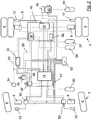
- Fig. 1 shows a schematic representation of a pressure medium-operated brake system, in particular a compressed air-operated brake system.
- brake systems are used, for example, in commercial vehicles, in particular trucks and buses.
- the electrically controlled brake system shown only shows a few selected components.
- the motor vehicle shown here has a front axle 2 and a rear axle 4.
- the invention is not limited to two-axle vehicles. Rather, motor vehicles with more than two axles, in particular several rear axles and / or several front axles, can also be used.
- a motor vehicle is understood to mean a tractor vehicle or a motor vehicle without a train function, for example a bus.
- the motor vehicle has wheels 6 on the front axle 2 and on the rear axle 4, which are each provided with brake cylinders 8 for individual braking.
- the brake cylinders 8 are formed at least on the rear axle 4 as a combined service and spring brake cylinder.
- the service brake part is provided with a membrane which can be acted upon by compressed air and is pneumatically connected to the service brake system.
- the spring-loaded part is pneumatically separated from the service brake part and can be supplied with compressed air via a separate compressed air line.
- Speed sensing means 10 are respectively arranged on the wheels 6 in order to determine the respective wheel rotational speed.
- the speed sensing means 10 are connected via a front axle modulator 12 via electrical lines to a central module 14 of the electrically controlled brake system.
- ABS valves 16 Antilock Braking System
- for controlling the brake pressure of the brake cylinders 8 are connected to the front axle modulator 12 via compressed air lines and to the central module 14 of the brake system via electrical lines.
- the brake system also has a brake value sensor 18 'which detects a braking request from the driver.
- the brake value transmitter 18 ' comprises a pneumatic part and an electrical part.
- the pneumatic part is supplied with compressed air from a first compressed air reservoir 20.
- a pneumatic manipulated variable is generated by the brake value transmitter 18 ′, which is passed on to the brake cylinders 8 of the front axle 2 via compressed air lines.
- the pneumatic signals are only required in the event of redundancy, they are no longer taken into account in normal braking operation.
- the electrical part of the brake value transmitter 18 has an electrical sensor which detects the mechanical actuation of the brake pedal and generates a signal representing this actuation. This electrical signal is used to control the braking system on an electrical basis and is transmitted to the central module 14 as an electrical braking request signal.
- the speed sensor 10 transfers the wheel speed of the individual wheels 6 of the rear axle 4 to the rear axle modulator 22 via electrical lines .
- the rear axle modulator 22 is connected to the central module 14 via an electrical line and via a data line and receives an electrical brake request signal from the brake value transmitter 18 ′ from the central module 14.
- the brake pressure in the brake cylinders 8 of the rear wheels 6 is controlled via valves arranged in the rear axle modulator 22.
- the rear air modulator 22 takes the compressed air required for this purpose from a second compressed air reservoir 24.
- the brake cylinders 8 of the rear axle 4 are preferably designed as combined service and spring brake cylinders, in order to provide a parking brake function in addition to the service brake.
- the spring-loaded part of the brake cylinder 8 is connected to a parking brake module 26 via pneumatic compressed air lines.
- the parking brake module 26 has an electronic control device which u. a. is used to adjust the parking brake.
- the valves of the parking brake module 26 are actuated in such a way that the brake pressure which arises in the pressure line approximately corresponds to the brake pressure setpoint. A braking effect is then achieved via spring brake cylinders.
- the invention is not limited to a parking brake module 26 with all components of the parking brake device. Rather, the electrical control device for performing the parking brake function in connection with the invention can also be referred to as a parking brake module 26.
- the rear axle modulator 22 is also connected to the central module 14 via a data line.
- the front axle modulator 12 is also connected to the central module 14 via a data line.
- the parking brake module 26 is connected via a data line 28 to an electrical actuating device 30 of the parking brake device, wherein a PWM signal can be transmitted via the data line 28 or the data line 28 is designed entirely or partially as a CAN bus, or preferably entirely or partially as an inexpensive LIN -Bus is trained.
- the parking brake module 26 and the electrical actuator 30 are powered by a power supply device, e.g. a vehicle battery as a first power supply 32, supplied with electricity via an electrical line.
- a power supply device e.g. a vehicle battery as a first power supply 32, supplied with electricity via an electrical line.
- This power supply device 32 also supplies the central module 14 of the braking system with power via a further electrical line.
- the parking brake module 26 is connected to the central module 14 via a data line 33, in particular a vehicle data bus or CAN bus.
- a steering angle sensor 34 is also arranged on this data line 33, the data of which is transferred via the data line 33 to the central module 14 of the braking system.
- the steering angle sensor 34 is e.g. attached to the steering column and passes on information about the driver's steering movement to the electronics of the brake system.
- the parking brake module 26 is connected via a compressed air line to a third compressed air reservoir 36 for supplying compressed air.
- the brake system shown furthermore has a driving dynamics sensor module 38, in particular an ESC module (Electronic Stability Control), wherein the sensor function of the ESC module enables corrective intervention in the engine and brake control in stability-critical driving situations and advantageously a tilting within the limits of physical limits , Skidding, turning and / or buckling of the motor vehicle can be prevented.
- ESC module Electronic Stability Control
- the driving dynamics sensor module 38, the parking brake module 26 and the rear axle modulator 22 can be arranged in a common control device 40, which is indicated by a dashed frame in FIG Fig. 1 is shown.
- Arranging the individual modules or the individual control functions of the respective modules in a common control device 40 has the advantage that less Space and less electrical and possibly pneumatic lines are required. At the same time, the assembly effort and the assembly costs are reduced.
- the motor vehicle described so far is also suitable for coupling a trailer vehicle.
- the brake system has a trailer control valve 42, which is used to control the brake pressure of a coupled trailer vehicle.
- the trailer control valve 42 is connected to a fourth compressed air reservoir 44 via a compressed air line for supplying compressed air.
- the trailer control valve 42 passes on the compressed air of the compressed air reservoir 44 in accordance with electrical and / or pneumatic control signals to the braking system of the trailer vehicle.
- the compressed air storage containers 20, 24, 36 and 44 are supplied via a compressed air supply system, not shown here, e.g. a compressor driven by the motor vehicle, filled with compressed air.
- a compressed air supply system not shown here, e.g. a compressor driven by the motor vehicle, filled with compressed air.
- an electrical plug connection 46 is provided for the power supply and for the transmission of data signals for the trailer vehicle.
- a pressure for the brake cylinders 8 is determined by means of an electrical brake request signal via the central module 14 and regulated by the front axle modulator 12 and the rear axle modulator 22.
- redundancy is to be established according to the invention via the parking brake, in which the driver can brake the motor vehicle as usual using the brake pedal.
- the brake value transmitter 18 'and the electrical actuating device 30 of the parking brake have a data line 48 for establishing a data connection.
- the brake request signal from the brake value transmitter 18 ' is transferred directly to the electrical actuating device 30 of the parking brake, which acts as a relay, in order to control the brake cylinders 8 on the rear axle via the parking brake module 26 directly via the data line 28 in accordance with the driver's braking request.
- the data line 48 is preferably an inexpensive LIN bus. However, it is also conceivable to use a CAN bus or a PWM signal, as well as to use any network structure that is suitable for transmitting the brake request signal. Furthermore, different data lines can be combined with one another.
- the arrangement of the data line 48 in the driver's cabin between the brake pedal of the brake value transmitter 18 'and the manual actuation unit of the electrical actuation device 30 saves costs and assembly effort.
- the invention is not limited to such an arrangement for establishing a data connection between the brake value transmitter 18 ′ and the parking brake module 26. Rather, according to an alternative embodiment of the invention, there is a direct, but not shown, data connection between the brake value transmitter 18 'and the parking brake module 26 via an in Fig. 1 Data line, not shown, is provided.
- the data connection according to the invention between the brake value transmitter 18 'and the parking brake module 26 enables according to the legal requirements a redundancy on the rear axle 4 via the parking brake device, wherein the pneumatic redundancy on the rear axle 4 can advantageously be saved.
- Fig. 2 shows a schematic representation of a brake system without pneumatic redundancy.
- the second exemplary embodiment is essentially the same as the first exemplary embodiment.
- the same reference numerals designate the same parts.
- the in Fig. 2 shown brake value transmitter 18 "has in addition to a power supply line to the first power supply 32 and a power supply line to the second power supply 52 only data lines with which the electrical braking request signal, which corresponds to the driver's braking request to the central module 14 and to wheel modules 50 on the front axle 2 of the Motor vehicle is transmitted, wherein the wheel modules 50 control the brake cylinders 8 of the wheels 6 in accordance with the braking request signal.
- the brake system can have a central brake unit 14 ', which includes the central module 14 of the brake system and the brake value transmitter 18'.
- This power supply device 52 enables the electronically controlled braking system to operate even if the first energy supply 32 fails, which provides additional reliability of the braking system since the other energy supply can maintain all braking functions of the electrically controlled braking system.
- the data lines 48 and 28 can be designed differently, but preferably as an inexpensive LIN bus.
- a data line (not shown) directly between the brake value transmitter 18 ′′ and the parking brake module 26 or the common control device 40 for transmitting the brake request signal is also conceivable.
- the brake value transmitter 18 ′′ can transmit a corresponding brake request signal to the parking brake device, so that the rear axle 4 is braked with the aid of the spring-loaded brake cylinder Main battery 32 of the motor vehicle is interrupted.
- a pressure-medium-operated brake system do not represent any restriction. Individual parts of the brake system can be arranged or distributed in any way.
Description
Die Erfindung betrifft ein druckmittelbetriebenes Bremssystem für ein Kraftfahrzeug, insbesondere Nutzfahrzeug, mit einer Betriebsbremseinrichtung und einer Feststellbremseinrichtung gemäß dem Oberbegriff von Anspruch 1 sowie ein Kraftfahrzeug mit einem derartigen Bremssystem.The invention relates to a pressure medium-operated brake system for a motor vehicle, in particular a commercial vehicle, with a service brake device and a parking brake device according to the preamble of claim 1 and a motor vehicle with such a brake system.
Aus
Es ist vorgesehen, dass die von den Feststellbremsaktuatoren der Feststellbremse aufzubringenden Bremskräfte über eine ABS-Regelschleife bestimmt werden und dass die Feststellbremsaktuatoren gemäß den bestimmten aufzubringenden Bremskräften betätigt werden.It is provided that the braking forces to be applied by the parking brake actuators of the parking brake are determined via an ABS control loop and that the parking brake actuators are actuated in accordance with the determined braking forces to be applied.
Elektronische Bremssysteme sind üblicherweise derart ausgestaltet, dass die Bremssteuermodule u. a. elektrische Signale von einem Bremswertgeber erhalten, welcher zur Erfassung des Bremswunsches des Fahrers des Kraftfahrzeugs dient. Diese elektrischen Signale entsprechen somit einer vom Fahrer vorgegebenen Bremswertanforderung und werden von der Fahrzeugelektronik ausgewertet. In Abhängigkeit von weiteren Größen, wie z.B. Beladung, wird die Bremskraftverteilung auf die Achsen des Kraftfahrzeugs bestimmt und die Bremssteuermodule für die Vorder- und die Hinterachsen entsprechend angesteuert.Electronic brake systems are usually designed such that the brake control modules u. a. receive electrical signals from a brake value transmitter, which is used to detect the braking request of the driver of the motor vehicle. These electrical signals thus correspond to a braking value requirement specified by the driver and are evaluated by the vehicle electronics. Depending on other sizes, e.g. Loading, the braking force distribution on the axles of the motor vehicle is determined and the brake control modules for the front and rear axles are controlled accordingly.
Ferner weist ein gattungsgemäßes Bremssystem eine Feststellbremseinrichtung auf. Hierzu sind bevorzugt die Räder mindestens einer Hinterachse mit zumeist kombinierten Betriebs- und Federspeicherbremszylindern ausgebildet. Sind die Federspeicherteile der Feststellbremse entlüftet, legt eine Speicherfeder die Bremse ein, um das Kraftfahrzeug auch im drucklosen Zustand sicher zu halten. Im Fahrbetrieb wird hingegen der Federspeicherteil der Feststellbremseinrichtung belüftet, so dass die Speicherfeder die Bremse nicht mehr anlegt. In diesem Fall wird das Kraftfahrzeug über die Betriebsbremszylinder von der Betriebsbremse eingebremst.Furthermore, a generic brake system has a parking brake device. For this purpose, the wheels of at least one rear axle are preferably designed with mostly combined service and spring brake cylinders. When the spring-loaded parts of the parking brake have been vented, a spring-loaded spring applies the brake to keep the motor vehicle secure even when depressurized. On the other hand, the spring-loaded part of the parking brake device is ventilated during driving, so that the spring-loaded spring no longer applies the brake. In this case, the motor vehicle is braked by the service brake via the service brake cylinders.
Aus Sicherheitsgründen ist bei Kraftfahrzeugen mit einem elektronisch geregelten Bremssystem eine Redundanz, z.B. in Form eines rein pneumatischen Steuersignals zur Aussteuerung des Bremsdruckes vorgesehen. Bei einem Ausfall, insbesondere der elektrischen bzw. elektronischen Komponenten, eines derartigen Bremssystems wird bei einer Bremsung das rein pneumatische Steuersignal wirksam und das Fahrzeug kann sicher zum Stehen gebracht werden.For safety reasons, redundancy in motor vehicles with an electronically controlled braking system, e.g. provided in the form of a purely pneumatic control signal for controlling the brake pressure. In the event of a failure, in particular of the electrical or electronic components, of such a braking system, the purely pneumatic control signal becomes effective during braking and the vehicle can be brought to a safe stop.
Eine Redundanz des Bremssystems kann ein- oder zweikreisig ausgelegt sein. Bei einkreisiger Redundanz ist nur einer von zwei unabhängig voneinander wirkenden Bremskreisen redundant ausgelegt, wobei es sich hierbei üblicherweise um den Vorderachs-Bremskreis handelt und bei zweikreisiger Redundanz sind hingegen beide Bremskreise, nämlich der Vorderachs-Bremskreis und der Hinterachs-Bremskreis, redundant ausgelegt. Da die Hinterachse jedoch ein ständig wechselndes Last-/Leer-Verhältnis aufweist, welches im Wesentlichen von der Zuladung abhängig ist, ist die Auslegung der Redundanz auf dem Hinterachs-Bremskreis schwierig.Redundancy of the braking system can be designed with one or two circuits. With single-circuit redundancy, only one of two independently operating brake circuits is designed redundantly, which is usually the front-axle brake circuit, and with double-circuit redundancy, however, both brake circuits, namely the front-axle brake circuit and the rear-axle brake circuit, are designed redundantly. However, since the rear axle has a constantly changing load / empty ratio, which essentially depends on the payload, it is difficult to design the redundancy on the rear axle brake circuit.
Nach alledem liegt der Erfindung die Aufgabe zugrunde, die Funktionsweise von elektronisch geregelten Bremssystemen der eingangs genannten Art zu verbessern, insbesondere die Ausfallsicherheit bei Systemen mit einkreisiger Redundanz zu erhöhen, um durch die einkreisige Redundanz das Bremssystem einfacher und kostengünstiger gestalten zu können.After all, the invention has for its object to improve the functioning of electronically controlled braking systems of the type mentioned, in particular to increase the reliability in systems with single-circuit redundancy, in order to make the braking system easier and cheaper by the single-circuit redundancy.
Die Erfindung löst diese Aufgabe mit den Merkmalen eines druckmittelbetriebenen Bremssystems gemäß Anspruch 1 sowie mit einem Kraftfahrzeug gemäß Anspruch 13.The invention solves this problem with the features of a pressure medium-operated brake system according to claim 1 and with a motor vehicle according to claim 13.
Das erfindungsgemäße druckmittelbetriebene Bremssystem für ein Kraftfahrzeug, insbesondere Nutzfahrzeug, umfasst eine Betriebsbremseinrichtung und eine Feststellbremseinrichtung, wobei die Betriebsbremseinrichtung zur Bereitstellung einer Betriebsbremsfunktion des Kraftfahrzeugs im Fahrbetrieb und die Feststellbremseinrichtung zum Feststellen des Kraftfahrzeugs dient.The pressure medium-operated brake system according to the invention for a motor vehicle, in particular a commercial vehicle, comprises a service brake device and a parking brake device, the service brake device being provided a service brake function of the motor vehicle while driving and the parking brake device is used to lock the motor vehicle.
Dazu weist die Feststellbremseinrichtung ein Feststellbremsmodul und eine mit dem Feststellbremsmodul gekoppelte elektrische Betätigungseinrichtung auf, welche üblicherweise als Handbetätigungseinheit im Fahrerhaus des Kraftfahrzeugs angeordnet ist. In dem Feststellbremsmodul sind üblicherweise eine Vielzahl oder alle Komponenten der Feststellbremseinrichtung, insbesondere Ventileinrichtungen, Relaisventil und Steuerelektronik, in einer einzigen Baugruppe zusammengefasst, um die Feststellbremsfunktion der Feststellbremseinrichtung zu ermöglichen.For this purpose, the parking brake device has a parking brake module and an electrical actuating device coupled to the parking brake module, which is usually arranged as a manual actuation unit in the driver's cab of the motor vehicle. In the parking brake module, a large number or all components of the parking brake device, in particular valve devices, relay valve and control electronics, are usually combined in a single assembly in order to enable the parking brake function of the parking brake device.
Als Feststellbremsmodul wird im Zusammenhang mit der Erfindung jedoch auch die Steuerelektronik der Feststellbremseinrichtung alleine bezeichnet, wenn die weiteren Komponenten der Feststellbremseinrichtung separat angeordnet sind. So ist es beispielsweise möglich, dass das Feststellbremsmodul lediglich als ein Abschnitt auf einer Leiterplatte anzusehen ist, wobei das Feststellbremsmodul mit anderen Steuerelektroniken weiterer Module des elektronischen Bremssystems auf einer gemeinsamen Leiterplatte angeordnet sein kann, um den Aufwand für die Verlegung von elektrischen und ggf. pneumatischen Leitungen bzw. den Montageaufwand zu reduzieren.In the context of the invention, however, the parking brake module is also referred to as the parking brake module if the other components of the parking brake device are arranged separately. For example, it is possible for the parking brake module to be viewed only as a section on a printed circuit board, the parking brake module being able to be arranged on a common printed circuit board with other control electronics of further modules of the electronic braking system, in order to reduce the effort involved in laying electrical and possibly pneumatic ones Reduce lines and assembly costs.
Die Betriebsbremseinrichtung weist erfindungsgemäß einen Bremswertgeber zum Erzeugen mindestens eines elektrischen Bremsanforderungssignals auf, wobei das elektrische Bremsanforderungssignal aus der Pedalbetätigung des Fahrers erzeugt wird. Je nach Ausgestaltung des Bremswertgebers können zusätzlich zu dem mindestens einen elektrischen Bremsanforderungssignal aus der Pedalbetätigung des Fahrers entsprechende pneumatische Drücke zum Be- und Entlüften der Bremszylinder erzeugt werden.According to the invention, the service brake device has a brake value transmitter for generating at least one electrical brake request signal, the electrical brake request signal being generated from the driver's pedal actuation. Depending on the design of the brake value transmitter, in addition to the at least one electrical brake request signal from the driver's pedal actuation, corresponding pneumatic pressures for ventilating and venting the brake cylinders can be generated.
Das erfindungsgemäße Bremssystem zeichnet sich durch mindestens eine Datenleitung aus, mit der der Bremswertgeber mittelbar oder unmittelbar mit dem Feststellbremsmodul zum Herstellen einer Datenverbindung verbunden ist. Über diese Datenleitung wird das vom Bremswertgeber erzeugte Bremsanforderungssignal dem Feststellbremsmodul bzw. der in dem Feststellbremsmodul angeordneten Steuerelektronik der Feststellbremseinrichtung mittelbar oder unmittelbar übergeben.The brake system according to the invention is characterized by at least one data line with which the brake value transmitter is connected directly or indirectly to the parking brake module for establishing a data connection. Via this data line, the brake request signal generated by the brake value transmitter is arranged in the parking brake module or in the parking brake module Control electronics of the parking brake device directly or indirectly.
Durch die direkte Übertragung des Bremsanforderungssignals an die Feststellbremseinrichtung lässt sich vorteilhaft die Bremswirkung an der Hinterachse bei einem Ausfall einzelner Komponenten, Signalleitungen und/oder Versorgungsleitungen nicht nur sicherstellen, sondern auch für den Fahrer komfortabel durch Betätigung des Bremspedals steuern.Through the direct transmission of the brake request signal to the parking brake device, the braking effect on the rear axle in the event of a failure of individual components, signal lines and / or supply lines can advantageously not only be ensured, but can also be conveniently controlled for the driver by actuating the brake pedal.
Mittels der Feststellbremseinrichtung wird somit eine Redundanz für die Betriebsbremskreise, insbesondere den Hinterachs-Bremskreis, geschaffen, welche nicht wie üblich vom Fahrer manuell betätigt werden muss. Das übermittelte Bremsanforderungssignal ermöglicht dem Fahrer vorteilhaft ein Einbremsen des Kraftfahrzeugs mit dem Bremspedal auch dann, wenn die Betriebsbremseinrichtung ausgefallen ist, obwohl das Einbremsen des Kraftfahrzeugs dann über die Feststellbremseinrichtung erfolgt.The parking brake device thus creates redundancy for the service brake circuits, in particular the rear-axle brake circuit, which does not have to be manually operated by the driver as usual. The transmitted brake request signal advantageously enables the driver to brake the motor vehicle using the brake pedal even if the service brake device has failed, even though the motor vehicle is then braked via the parking brake device.
Gemäß einer bevorzugten Ausführungsform der Erfindung ist die Datenleitung zwischen dem Bremswertgeber und dem Feststellbremsmodul als ein LIN-Bus (Local Interconnect Network) ausgestaltet bzw. weist einen LIN-Bus auf. Unter einem LIN-Bus wird dabei ein einfaches serielles Bussystem zur Vernetzung von intelligenten Sensoren und Aktoren innerhalb des Kraftfahrzeugs verstanden, welches vorteilhaft kostengünstig eine einfache Datenübertragung ermöglicht.According to a preferred embodiment of the invention, the data line between the brake value transmitter and the parking brake module is designed as a LIN bus (Local Interconnect Network) or has a LIN bus. A LIN bus is understood to mean a simple serial bus system for networking intelligent sensors and actuators within the motor vehicle, which advantageously enables simple data transmission at low cost.
Gemäß einer weiteren bevorzugten Ausführungsform der Erfindung ist die Datenleitung zwischen dem Bremswertgeber und dem Feststellbremsmodul als ein CAN-Bus (Controller Area Network) ausgestaltet bzw. weist einen CAN-Bus auf. Unter einem CAN-Bus wird dabei ein serielles Bussystem zur Vernetzung von Steuergeräten und Sensoreinheiten innerhalb des Kraftfahrzeugs verstanden, welches vorteilhaft eine höhere Bandbreite als der LIN-Bus aufweist. Die Verwendung eines CAN-Busses hat sich als Standard in der Kraftfahrzeugtechnik durchgesetzt und ist deshalb vorteilhaft.According to a further preferred embodiment of the invention, the data line between the brake value transmitter and the parking brake module is designed as a CAN bus (Controller Area Network) or has a CAN bus. A CAN bus is understood to mean a serial bus system for networking control devices and sensor units within the motor vehicle, which advantageously has a higher bandwidth than the LIN bus. The use of a CAN bus has established itself as the standard in automotive engineering and is therefore advantageous.
Eine weitere bevorzugte Ausführungsform der Erfindung sieht vor, über die Datenleitung ein PWM-Signal (pulsweitenmoduliertes Signal) zu übertragen. PWM-Signale lassen sich einfach erzeugen und über jede elektrische Leitung übertragen.Another preferred embodiment of the invention provides for a PWM signal (pulse-width-modulated signal) to be transmitted via the data line. PWM signals can be easily generated and transmitted via any electrical line.
In einer weiteren bevorzugten Ausführungsform der Erfindung sind der Bremswertgeber und die elektrische Betätigungseinrichtung der Feststellbremseinrichtung jeweils unmittelbar mit dem Feststellbremsmodul zum Herstellen je einer Datenverbindung verbunden. Dabei können die jeweiligen Datenverbindungen unterschiedlich ausgebildet sein. Die Datenverbindung zwischen dem Bremswertgeber und dem Feststellbremsmodul ermöglich vorteilhaft die erfindungsgemäße Redundanz innerhalb des elektronisch geregelten Bremssystems.In a further preferred embodiment of the invention, the brake value transmitter and the electrical actuating device of the parking brake device are each directly connected to the parking brake module for establishing a respective data connection. The respective data connections can be designed differently. The data connection between the brake value transmitter and the parking brake module advantageously enables the redundancy according to the invention within the electronically controlled brake system.
In einer weiteren bevorzugten Ausführungsform der Erfindung sind der Bremswertgeber und das Feststellbremsmodul jeweils unmittelbar mit der elektrischen Betätigungseinrichtung der Feststellbremseinrichtung zum Herstellen je einer Datenverbindung verbunden. Dabei können die jeweiligen Datenverbindungen unterschiedlich ausgebildet sein. Die Datenverbindung zwischen dem Bremswertgeber und der elektrischen Betätigungseinrichtung der Feststellbremseinrichtung ergänzt auf vorteilhafter Weise die vorhandene Datenverbindung zwischen der elektrischen Betätigungseinrichtung der Feststellbremseinrichtung und dem Feststellbremsmodul, so dass für die Realisierung der erfindungsgemäßen Redundanz innerhalb des elektronisch geregelten Bremssystems lediglich eine kurze, kostengünstige Signalleitung, insbesondere innerhalb der Konsole vom Bremspedal zur Handbetätigungseinrichtung, notwendig ist. Dadurch lassen sich vorteilhafterweise Kosten und Montageaufwand einsparen.In a further preferred embodiment of the invention, the brake value transmitter and the parking brake module are each connected directly to the electrical actuating device of the parking brake device for establishing a data connection. The respective data connections can be designed differently. The data connection between the brake value transmitter and the electric actuating device of the parking brake device advantageously supplements the existing data connection between the electric actuating device of the parking brake device and the parking brake module, so that only a short, inexpensive signal line, in particular within, is implemented for the redundancy according to the invention within the electronically controlled braking system the console from the brake pedal to the manual control device is necessary. This advantageously saves costs and assembly effort.
In einer weiteren bevorzugten Ausführungsform der Erfindung sind die elektrische Betätigungseinrichtung der Feststellbremseinrichtung und das Feststellbremsmodul jeweils unmittelbar mit dem Bremswertgeber zum Herstellen je einer Datenverbindung verbunden. Dabei können die jeweiligen Datenverbindungen unterschiedlich ausgebildet sein, so dass bspw. eine Datenleitung als LIN-Bus und eine Datenleitung als CAN-Bus ausgebildet ist. Für die Realisierung der erfindungsgemäßen Redundanz innerhalb des elektronisch geregelten Bremssystems ist neben einer Datenleitung zwischen dem Bremswertgeber und dem Feststellbremsmodul vorteilhafterweise lediglich eine kurze, kostengünstige Signalleitung zwischen dem Bremswertgeber und der elektrischen Betätigungseinrichtung der Feststellbremseinrichtung notwendig, insbesondere innerhalb der Konsole vom Bremspedal zur Handbetätigungseinrichtung. Dadurch lassen sich vorteilhafterweise Kosten und Montageaufwand einsparen.In a further preferred embodiment of the invention, the electrical actuating device of the parking brake device and the parking brake module are each connected directly to the brake value transmitter for establishing a data connection. The respective data connections can be designed differently, so that, for example, a data line is designed as a LIN bus and a data line as a CAN bus. To implement the redundancy according to the invention within the electronically controlled brake system, in addition to a data line between the brake value transmitter and the parking brake module, advantageously only a short, inexpensive signal line between the brake value transmitter and the electrical actuating device is advantageous the parking brake device necessary, especially within the console from the brake pedal to the manual control device. This advantageously saves costs and assembly effort.
In einer weiteren bevorzugten Ausführungsform der Erfindung sind der Bremswertgeber, das Feststellbremsmodul und die elektrische Betätigungseinrichtung der Feststellbremseinrichtung jeweils unmittelbar miteinander zum Herstellen je einer Datenverbindung verbunden. Dabei können die jeweiligen Datenverbindungen unterschiedlich ausgebildet sein. Die Datenverbindung zwischen dem Bremswertgeber und der elektrischen Betätigungseinrichtung der Feststellbremseinrichtung ergänzt vorteilhafterweise die Datenverbindung zwischen der elektrischen Betätigungseinrichtung der Feststellbremseinrichtung und dem Feststellbremsmodul, um die erfindungsgemäße Redundanz innerhalb des elektronisch geregelten Bremssystems herzustellen. Die Datenverbindung zwischen dem Bremswertgeber und dem Feststellbremsmodul ermöglicht vorteilhafterweise eine zusätzliche Redundanz innerhalb des elektronisch geregelten Bremssystems.In a further preferred embodiment of the invention, the brake value transmitter, the parking brake module and the electrical actuating device of the parking brake device are each directly connected to one another for establishing a data connection. The respective data connections can be designed differently. The data connection between the brake value transmitter and the electrical actuating device of the parking brake device advantageously supplements the data connection between the electrical actuating device of the parking brake device and the parking brake module in order to establish the redundancy according to the invention within the electronically controlled braking system. The data connection between the brake value transmitter and the parking brake module advantageously enables additional redundancy within the electronically controlled brake system.
Gemäß einer weiteren bevorzugten Ausführungsform der Erfindung weist die Feststellbremseinrichtung wenigstens einen Betriebs- und Federspeicherbremszylinder auf. Derartige kombinierte Betriebs- und Federspeicherbremszylinder werden üblicherweise an der Hinterachse verwendet und weisen einen Membranzylinder für die Betriebsbremse sowie einen Federspeicherzylinder für die Feststellbremse auf. Beide Bremszylinder sind unabhängig voneinander betätigbar, wobei eine Bremsung erzielt wird, wenn der Betriebsbremszylinder mit Druck beaufschlagt wird oder wenn am Federspeicherbremszylinder ein Druckabfall entsteht. Somit ist auch bei Fehlen von Druckluft eine Bremsung des Kraftfahrzeugs möglich.According to a further preferred embodiment of the invention, the parking brake device has at least one service and spring brake cylinder. Such combined service and spring-loaded brake cylinders are usually used on the rear axle and have a membrane cylinder for the service brake and a spring-loaded cylinder for the parking brake. Both brake cylinders can be actuated independently of one another, braking being achieved if pressure is applied to the service brake cylinder or if there is a pressure drop on the spring brake cylinder. Braking of the motor vehicle is thus possible even in the absence of compressed air.
Durch die Verwendung von kombinierten Betriebs- und Federspeicherbremszylindern lassen sich vorteilhafterweise Kosten, Platz und Aufwand für die Verlegung von pneumatischen und unter Umständen auch elektrischen Leitungen einsparen. Alternativ ist jedoch ebenso die Verwendung einer elektromechanischen Feststellbremse zum Feststellen des Kraftfahrzeugs möglich. Die elektromechanische Feststellbremse lässt sich ebenfalls über ein Feststellbremsmodul mit entsprechender Steuerelektronik durch den Bremswertgeber bzw. die elektrische Betätigungseinrichtung der Feststellbremseinrichtung ansteuern.The use of combined service and spring-loaded brake cylinders advantageously saves costs, space and effort for the laying of pneumatic and possibly also electrical lines. Alternatively, however, the use of an electromechanical parking brake for locking the motor vehicle is also possible. The electromechanical parking brake can also be operated via a parking brake module control with appropriate control electronics by the brake value transmitter or the electrical actuating device of the parking brake device.
In einer weiteren bevorzugten Ausführungsform der Erfindung weist das Bremssystem zusätzlich zu einer ersten Energieversorgung mindestens eine weitere, von der ersten Energieversorgung unabhängige Energieversorgung auf. Die erste Energieversorgung umfasst dabei eine Haupt-Batterie, insbesondere Haupt-Kraftfahrzeugbatterie, mit der im Wesentlichen die elektrische Betätigungseinrichtung der Feststellbremseinrichtung, das Feststellbremsmodul, der Bremswertgeber und ein Zentralmodul des Bremssystems elektrisch versorgt werden.In a further preferred embodiment of the invention, in addition to a first energy supply, the brake system has at least one further energy supply that is independent of the first energy supply. The first energy supply comprises a main battery, in particular a main motor vehicle battery, with which the electrical actuating device of the parking brake device, the parking brake module, the brake value transmitter and a central module of the brake system are essentially supplied with electricity.
Die weitere Energieversorgung ist durch eine Sicherheits-Batterie, insbesondere Kraftfahrzeugbatterie, gegeben. Diese dient in dem Fall, dass die Haupt-Batterie ausfällt, im Wesentlichen der Stromversorgung der elektrischen Betätigungseinrichtung der Feststellbremseinrichtung, des Feststellbremsmoduls, des Bremswertgebers und des Zentralmoduls des Bremssystems sowie der elektrischen Versorgung der Radmodule an der Vorderachse. Durch die zusätzlichen Anschlüsse für die elektrische Versorgung der Radmodule an der Vorderachse ist vorteilhaft eine zusätzliche Ausfallsicherung gegenüber der Haupt-Batterie gegeben.The further energy supply is provided by a safety battery, in particular a motor vehicle battery. In the event that the main battery fails, this essentially serves to supply the electrical actuation device of the parking brake device, the parking brake module, the brake value transmitter and the central module of the braking system, as well as the electrical supply to the wheel modules on the front axle. The additional connections for the electrical supply of the wheel modules on the front axle advantageously provide additional fail-safe protection compared to the main battery.
Gemäß einer weiteren bevorzugten Ausführungsform der Erfindung ist der Bremswertgeber derart ausgestaltet, um ausschließlich elektrische Bremsanforderungssignale bereitzustellen. Bei dieser Ausführungsform entfällt die rein pneumatische Redundanz. Der Verzicht der pneumatischen Redundanz über pneumatische Leitungen am Bremswertgeber sorgt vorteilhafterweise für Einsparungen von Verrohrungen und somit für Kosten- und Aufwandsersparnis bei der Montage.According to a further preferred embodiment of the invention, the brake value transmitter is designed in such a way that it only provides electrical brake request signals. In this embodiment, the purely pneumatic redundancy is eliminated. The elimination of pneumatic redundancy via pneumatic lines on the brake value transmitter advantageously saves on pipework and thus saves costs and effort during installation.
Gemäß einer alternativen Ausführungsform der Erfindung ist der Bremswertgeber derart ausgestaltet, um zusätzlich zu den elektrischen Bremsanforderungssignalen ausschließlich für die Vorderachse pneumatische Bremsanforderungssignale bereitzustellen. Bei Bremssystemen mit einkreisig rein pneumatisch ausgelegter Redundanz ist nur ein Bremskreis redundant ausgelegt, welches üblicherweise der Vorderachs-Bremskreis ist.According to an alternative embodiment of the invention, the brake value transmitter is designed in such a way that, in addition to the electrical brake request signals, pneumatic brake request signals are provided exclusively for the front axle. In brake systems with single-circuit purely pneumatic redundancy, only one brake circuit is designed redundantly, which is usually the front axle brake circuit.
Aufgrund der gesetzlichen Vorgaben muss, insbesondere bei LKWs mit hoher Last an der Hinterachse, die Bremswirkung auch bei Ausfall der Betriebsbremse sichergestellt sein. Durch die direkte Übertragung des Bremsanforderungssignals an die Feststellbremseinrichtung lässt sich vorteilhafterweise die Bremswirkung somit auch an der Hinterachse bei einem Ausfall einzelner Komponenten, Signalleitungen und/oder Versorgungsleitungen bei einer einkreisig ausgebildeten Redundanz des Bremssystems sicherstellen.Due to the legal requirements, especially in the case of trucks with high loads on the rear axle, the braking effect must be ensured even if the service brake fails. Through the direct transmission of the braking request signal to the parking brake device, the braking effect can advantageously also be ensured on the rear axle in the event of failure of individual components, signal lines and / or supply lines with a single-circuit redundancy of the braking system.
In einer weiteren Ausführungsform der Erfindung ist das Feststellbremsmodul oder die Steuereinheit des Feststellbremsmoduls in einem Steuergerät angeordnet, wobei das Steuergerät neben einer Steuerfunktion des Feststellbremsmoduls weitere Steuerfunktionen bzw. Sensorfunktionen beinhaltet, insbesondere die Steuerfunktionen eines Hinterachsmodulators und/oder die Sensorfunktionen eines Fahrdynamiksensormoduls. Das hat den Vorteil, dass die einzelnen Gehäuse der integrierten Module entfallen und ein gemeinsames Gehäuse des Steuergerätes verwendet wird, wodurch weniger Platz und weniger elektrische und ggf. pneumatische Leitungen benötigt werden und somit der Montageaufwand und die Montagekosten reduziert werden. Ferner reduziert sich vorteilhaft die Anzahl der Anschlüsse durch Verwendung gemeinsamer Anschlüsse eines Steuergerätes.In a further embodiment of the invention, the parking brake module or the control unit of the parking brake module is arranged in a control unit, the control unit comprising, in addition to a control function of the parking brake module, further control functions or sensor functions, in particular the control functions of a rear axle modulator and / or the sensor functions of a vehicle dynamics sensor module. This has the advantage that the individual housings of the integrated modules are dispensed with and a common housing of the control device is used, as a result of which less space and less electrical and, if applicable, pneumatic lines are required, and thus the assembly effort and the assembly costs are reduced. Furthermore, the number of connections is advantageously reduced by using common connections of a control device.
Um die Ausfallsicherheit des Bremssystems zu erhöhen, werden die in dem Steuergerät enthaltenen Steuerfunktionen der einzelnen Module bevorzugt von mindestens zwei unterschiedlichen Prozessoren übernommen, so dass eine zusätzliche Redundanz geschaffen wird. Bevorzugt sind die Prozessoren unabhängig voneinander betriebsfähig, so dass im Fehlerfall des einen Prozessors keine Beeinflussung des jeweils nicht fehlerhaften Prozessors erfolgt.In order to increase the reliability of the brake system, the control functions of the individual modules contained in the control unit are preferably carried out by at least two different processors, so that additional redundancy is created. The processors are preferably operable independently of one another, so that in the event of a fault in one processor there is no influence on the processor that is not faulty.
Des Weiteren löst die Erfindung die o. g. Aufgabe mit einem Kraftfahrzeug, insbesondere Nutzfahrzeug, welches ein erfindungsgemäßes Bremssystem aufweist.Furthermore, the invention achieves the above-mentioned object with a motor vehicle, in particular a commercial vehicle, which has a braking system according to the invention.
Weitere Ausführungsformen ergeben sich aus den Ansprüchen sowie aus den anhand der Zeichnung näher erläuterten Ausführungsbeispielen. In der Zeichnung zeigen:
- Fig. 1
- eine schematische Darstellung eines Bremssystems mit einfacher pneumatischer Redundanz an der Vorderachse und
- Fig. 2
- eine schematische Darstellung eines Bremssystems ohne pneumatische Redundanz.
- Fig. 1
- a schematic representation of a braking system with simple pneumatic redundancy on the front axle and
- Fig. 2
- a schematic representation of a braking system without pneumatic redundancy.
In den Figuren sind gleichartige Teile mit identischen Bezugsziffern versehen, so dass mit der Erläuterung eines Teils in einer Figur dieses Teil auch in anderen Figuren beschrieben ist.In the figures, similar parts are provided with identical reference numerals, so that the explanation of a part in one figure also describes this part in other figures.
Ferner sind in den Figuren elektrische Leitungen als durchgezogene Linien, pneumatische Leitungen als punktierte Linien und Datenleitungen als strichpunktierte Linien gezeichnet.Furthermore, electrical lines are drawn as solid lines, pneumatic lines as dotted lines and data lines as dash-dotted lines in the figures.
Das in
Das Kraftfahrzeug weist Räder 6 an der Vorderachse 2 sowie an der Hinterachse 4 auf, die jeweils zur individuellen Abbremsung mit Bremszylindern 8 versehen sind. Die Bremszylinder 8 sind zumindest an der Hinterachse 4 als kombinierte Betriebs- und Federspeicherbremszylinder ausgebildet.The motor vehicle has
Bei derartigen kombinierten Betriebs- und Federspeicherbremszylindern ist der Betriebsbremsteil mit einer durch Druckluft beaufschlagbaren Membran versehen und pneumatisch mit der Betriebsbremsanlage verbunden. Der Federspeicherteil ist pneumatisch von dem Betriebsbremsteil getrennt und über eine gesonderte Druckluftleitung mit Druckluft beaufschlagbar. Bei Druckluftbeaufschlagung des Federspeicherteils wird eine Speicherfeder vorgespannt und somit eine Bremswirkung verhindert. Die Bremswirkung der Feststellbremse wird durch Entlüftung des Federspeicherteils erzielt.In such combined service and spring brake cylinders, the service brake part is provided with a membrane which can be acted upon by compressed air and is pneumatically connected to the service brake system. The spring-loaded part is pneumatically separated from the service brake part and can be supplied with compressed air via a separate compressed air line. When compressed air is applied to the spring storage part, a storage spring is preloaded and a braking effect is thus prevented. The braking effect of the parking brake is achieved by venting the spring-loaded part.
An den Rädern 6 sind jeweils Geschwindigkeits-Sensiermittel 10 angeordnet, um die jeweilige Raddrehgeschwindigkeit zu ermitteln. Die Geschwindigkeits-Sensiermittel 10 sind über einen Vorderachsmodulator 12 über elektrische Leitungen mit einem Zentralmodul 14 des elektrisch geregelten Bremssystems verbunden. Ferner sind ABS-Ventile 16 (Antilock Braking System) zum Ansteuern des Bremsdruckes der Bremszylinder 8 über Druckluftleitungen mit dem Vorderachsmodulator 12 verbunden sowie über elektrische Leitungen mit dem Zentralmodul 14 des Bremssystems.Speed sensing means 10 are respectively arranged on the
Das Bremssystem weist ferner einen Bremswertgeber 18' auf, der einen Bremswunsch des Fahrers erfasst. Der Bremswertgeber 18' umfasst einen pneumatischen Teil und einen elektrischen Teil.The brake system also has a brake value sensor 18 'which detects a braking request from the driver. The brake value transmitter 18 'comprises a pneumatic part and an electrical part.
Der pneumatische Teil wird von einem ersten Druckluftvorratsbehälter 20 mit Druckluft versorgt. Durch Betätigung eines Bremspedals wird von dem Bremswertgeber 18' eine pneumatische Stellgröße erzeugt, die über Druckluftleitungen an die Bremszylinder 8 der Vorderachse 2 weitergeleitet wird. Die pneumatischen Signale werden jedoch nur im Redundanzfall benötigt, im normalen Bremsbetrieb werden sie nicht weiter berücksichtigt.The pneumatic part is supplied with compressed air from a first
Der elektrische Teil des Bremswertgebers 18' weist einen elektrischen Sensor auf, welcher die mechanische Betätigung des Bremspedals erfasst und ein diese Betätigung repräsentierendes Signal erzeugt. Dieses elektrische Signal dient zur Steuerung des Bremssystems auf elektrischer Basis und wird als elektrisches Bremsanforderungssignal dem Zentralmodul 14 übergeben.The electrical part of the brake value transmitter 18 'has an electrical sensor which detects the mechanical actuation of the brake pedal and generates a signal representing this actuation. This electrical signal is used to control the braking system on an electrical basis and is transmitted to the
An der Hinterachse 4 befindet sich ein Hinterachsmodulator 22 mit einer eigenständigen Elektronik zum Regeln der Bremsfunktion an den Rädern 6 der Hinterachse 4. Dazu wird von den Geschwindigkeits-Sensiermitteln 10 die Raddrehzahl der einzelnen Räder 6 der Hinterachse 4 an den Hinterachsmodulator 22 über elektrische Leitungen übergeben. Ferner ist der Hinterachsmodulator 22 über eine elektrische Leitung sowie über eine Datenleitung mit dem Zentralmodul 14 verbunden und empfängt von dem Zentralmodul 14 ein elektrisches Bremsanforderungssignal des Bremswertgebers 18'.On the
Der Bremsdruck in den Bremszylindern 8 der Hinterräder 6 wird über in dem Hinterachsmodulator 22 angeordnete Ventile gesteuert. Die Druckluft, die dazu erforderlich ist, entnimmt der Hinterachsmodulator 22 einem zweiten Druckluftvorratsbehälter 24.The brake pressure in the
Die Bremszylinder 8 der Hinterachse 4 sind bevorzugt als kombinierte Betriebs- und Federspeicherbremszylinder ausgebildet, um neben der Betriebsbremse auch eine Feststellbremsfunktion bereitzustellen. Dazu ist der Federspeicherteil des Bremszylinders 8 über pneumatische Druckluftleitungen mit einem Feststellbremsmodul 26 verbunden.The
Das Feststellbremsmodul 26 weist eine elektronische Steuereinrichtung auf, welche u. a. zum einstellbaren Betätigen der Feststellbremse dient. Dazu werden die Ventile des Feststellbremsmoduls 26 derart angesteuert, dass der sich in der Druckleitung einstellende Bremsdruck annähernd dem Bremsdruck-Sollwert entspricht. Über Federspeicherbremszylinder wird dann eine Bremswirkung erzielt.The
Die Erfindung ist jedoch nicht auf ein Feststellbremsmodul 26 mit allen Komponenten der Feststellbremseinrichtung beschränkt. Vielmehr kann auch die elektrische Steuereinrichtung zum Ausüben der Feststellbremsfunktion im Zusammenhang mit der Erfindung als Feststellbremsmodul 26 bezeichnet werden.However, the invention is not limited to a
Der Hinterachsmodulator 22 ist ferner über eine Datenleitung mit dem Zentralmodul 14 verbunden. Ebenso ist der Vorderachsmodulator 12 mit dem Zentralmodul 14 über eine Datenleitung verbunden.The
Das Feststellbremsmodul 26 ist über eine Datenleitung 28 mit einer elektrischen Betätigungseinrichtung 30 der Feststellbremseinrichtung verbunden, wobei über die Datenleitung 28 ein PWM-Signal übertragbar ist oder die Datenleitung 28 ganz oder teilweise als CAN-Bus ausgebildet ist oder aber bevorzugt ganz oder teilweise als kostengünstiger LIN-Bus ausgebildet ist.The
Das Feststellbremsmodul 26 und die elektrische Betätigungseinrichtung 30 werden von einer Stromversorgungseinrichtung, z.B. einer Fahrzeugbatterie als eine erste Energieversorgung 32, über eine elektrische Leitung mit Strom versorgt. Diese Stromversorgungseinrichtung 32 versorgt über eine weitere elektrische Leitung das Zentralmodul 14 des Bremssystems ebenfalls mit Strom.The
Des Weiteren ist das Feststellbremsmodul 26 über eine Datenleitung 33, insbesondere einen Fahrzeugdatenbus bzw. CAN-Bus, mit dem Zentralmodul 14 verbunden. An dieser Datenleitung 33 ist zudem ein Lenkwinkelsensor 34 angeordnet, dessen Daten über die Datenleitung 33 dem Zentralmodul 14 des Bremssystems übergeben werden. Der Lenkwinkelsensor 34 ist z.B. an der Lenksäule befestigt und gibt Informationen über die Lenkbewegung des Fahrers an die Elektronik des Bremssystems weiter.Furthermore, the
Schließlich ist das Feststellbremsmodul 26 über eine Druckluftleitung mit einem dritten Druckluftvorratsbehälter 36 zur Druckluftversorgung verbunden.Finally, the
Das in
Optional können das Fahrdynamiksensormodul 38, das Feststellbremsmodul 26 und der Hinterachsmodulator 22 in einem gemeinsamen Steuergerät 40 angeordnet sein, was durch einen gestrichelten Rahmen in
Das bisher beschriebene Kraftfahrzeug ist außerdem zur Ankopplung eines Anhängefahrzeugs geeignet. Dazu weist das Bremssystem ein Anhängersteuerventil 42 auf, welches zur Bremsdrucksteuerung eines angekoppelten Anhängefahrzeugs dient. Das Anhängersteuerventil 42 ist zur Druckluftversorgung über eine Druckluftleitung mit einem vierten Druckluftvorratsbehälter 44 verbunden. Das Anhängersteuerventil 42 gibt die Druckluft des Druckluftvorratsbehälters 44 entsprechend von elektrischen und/oder pneumatischen Steuersignalen an die Bremsanlage des Anhängefahrzeugs weiter.The motor vehicle described so far is also suitable for coupling a trailer vehicle. For this purpose, the brake system has a
Die Druckluftvorratsbehälter 20, 24, 36 und 44 werden über eine hier nicht dargestellte Druckluftversorgungsanlage, z.B. einem vom Kraftfahrzeug angetriebenen Kompressor, mit Druckluft befüllt.The compressed
Schließlich ist noch ein elektrischer Steckanschluss 46 zur Stromversorgung und zur Übermittlung von Datensignalen für das Anhängefahrzeug vorgesehen.Finally, an
Das in
In einem Redundanzfall, z.B. bei einem Ausfall der elektrischen Steuerung oder einem Ausfall einzelner Steuermodule erfolgt eine Umschaltung auf das pneumatische Signal am Bremswertgeber 18', welches jedoch nur die Vorderachse 2 ansteuert.In a redundancy case, e.g. in the event of a failure of the electrical control or a failure of individual control modules, there is a switchover to the pneumatic signal on the brake value transmitter 18 ', which, however, only controls the
Zum Sicherstellen der Bremsleistung im Störungsfall auch an der Hinterachse, soll erfindungsgemäß eine Redundanz über die Feststellbremse hergestellt werden, bei der der Fahrer wie gewohnt über das Bremspedal das Kraftfahrzeug abbremsen kann.In order to ensure the braking power in the event of a fault even on the rear axle, redundancy is to be established according to the invention via the parking brake, in which the driver can brake the motor vehicle as usual using the brake pedal.
Dazu weisen der Bremswertgeber 18' und die elektrische Betätigungseinrichtung 30 der Feststellbremse eine Datenleitung 48 zum Herstellen einer Datenverbindung auf. Bei einem Störungsfall des elektronisch geregelten Bremssystems, z.B. bei einem Ausfall des Zentralmoduls 14, wird das Bremsanforderungssignal des Bremswertgebers 18' unmittelbar der als Relais fungierenden elektrischen Betätigungseinrichtung 30 der Feststellbremse übergeben, um die Bremszylinder 8 an der Hinterachse über das Feststellbremsmodul 26 entsprechend dem Bremswunsch des Fahrers direkt über die Datenleitung 28 anzusteuern.For this purpose, the brake value transmitter 18 'and the
Bei der Datenleitung 48 handelt es sich bevorzugt um einen kostengünstigen LIN-Bus. Es ist jedoch ebenso eine Verwendung eines CAN-Busses oder eines PWM-Signals denkbar, wie auch die Verwendung einer beliebigen Netzstruktur, welche geeignet ist, das Bremsanforderungssignal zu übertragen. Ferner können verschiedene Datenleitungen miteinander kombiniert werden.The
Die Anordnung der Datenleitung 48 in der Fahrerkabine zwischen dem Bremspedal des Bremswertgebers 18' und der Handbetätigungseinheit der elektrischen Betätigungseinrichtung 30 spart Kosten und Montageaufwand. Die Erfindung ist jedoch nicht auf eine derartige Anordnung zum Herstellen einer Datenverbindung zwischen dem Bremswertgeber 18' und dem Feststellbremsmodul 26 beschränkt. Vielmehr ist gemäß einer alternativen Ausgestaltung der Erfindung eine direkte, hier jedoch nicht dargestellte Datenverbindung zwischen dem Bremswertgeber 18' und dem Feststellbremsmodul 26 über eine in
Ferner kann bei Verwendung einer derartigen vorstehend genannten, jedoch nicht in
Die erfindungsgemäße Datenverbindung zwischen dem Bremswertgeber 18' und dem Feststellbremsmodul 26 ermöglicht entsprechend den gesetzlichen Vorgaben eine Redundanz an der Hinterachse 4 über die Feststellbremseinrichtung, wobei vorteilhaft die pneumatische Redundanz an der Hinterachse 4 eingespart werden kann.The data connection according to the invention between the brake value transmitter 18 'and the
Der in
Alternativ, durch einen gestrichelten Rahmen in
Das Zentralmodul 14 oder die zentrale Bremseinheit 14' ist zusammen mit den Radmodulen 50, dem Bremswertgeber 18", der elektrischen Betätigungseinrichtung 30 und dem Feststellbremsmodul 26 oder dem gemeinsamen Steuergerät 40 über jeweils eine elektrische Stromversorgungsleitung mit einer weiteren Energieversorgung 52, insbesondere einer Sicherheits-Batterie, verbunden. Diese Stromversorgungseinrichtung 52 ermöglicht einen Betrieb des elektronisch geregelten Bremssystems auch bei Ausfall der ersten Energieversorgung 32, was zusätzliche Ausfallsicherheit des Bremssystems bietet, da die jeweils andere Energieversorgung alle Bremsfunktionen des elektrisch geregelten Bremssystems aufrecht erhalten kann.The
Bei dem in
Auch hier können die Datenleitungen 48 und 28 unterschiedlich ausgebildet sein, bevorzugt jedoch als kostengünstiger LIN-Bus. Ebenso ist zusätzlich oder alternativ eine nicht eingezeichnete Datenleitung direkt zwischen dem Bremswertgeber 18" und dem Feststellbremsmodul 26 oder dem gemeinsamen Steuergerät 40 zur Übertragung des Bremsanforderungssignals denkbar.Here too, the data lines 48 and 28 can be designed differently, but preferably as an inexpensive LIN bus. Likewise, in addition or as an alternative, a data line (not shown) directly between the
Falls die reguläre Regelung der Betriebsbremse an der Hinterachse 4 nicht funktioniert, kann der Bremswertgeber 18" ein entsprechendes Bremsanforderungssignal an die Feststellbremseinrichtung übermitteln, so dass mit Hilfe der Federspeicherbremszylinder eine Einbremsung der Hinterachse 4 erfolgt. Dies ist erfindungsgemäß sogar dann möglich, wenn die Stromversorgung der Haupt-Batterie 32 des Kraftfahrzeugs unterbrochen ist.If the regular regulation of the service brake on the
Die in
Claims (13)
- Pressurising-medium-operated brake system for a motor vehicle, in particular utility vehicle, having a service brake device and a parking brake device, wherein the parking brake device has a parking brake module (26) and an electric activation device (30) which is coupled to the parking brake module (26), and wherein the service brake device has a brake value generator (18',18") for generating at least one electric braking request signal,
characterized in that
the brake value generator (18', 18") is indirectly or directly connected to the parking brake module (26) by means of at least one data line in order to establish a data connection, and the braking request signal is transferred to the parking brake module (26) via this data line, in order in this way to actuate brake cylinders (8) in accordance with the driver's braking request. - Brake system according to Claim 1,
characterized in that
the data line is or has a LIN bus. - Brake system according to Claim 1 or 2,
characterized in that
the data line is or has a CAN bus. - Brake system according to one of the preceding claims,
characterized in that
a PWM signal can be transmitted via the data line. - Brake system according to one of the preceding claims,
characterized in that
the brake value generator (18', 18") and the electric activation device (30) of the parking brake device are each directly connected to the parking brake module (26), in order to establish a data connection in each case. - Brake system according to one of Claims 1 to 4,
characterized in that
the brake value generator (18', 18"), the parking brake module (26) and the electric activation device (30) of the parking brake device are each directly connected to one another, in order to establish a data connection in each case. - Brake system according to one of Claims 1 to 4,
characterized in that
the electric activation device (30) of the parking brake device and the parking brake module (26) are each directly connected to the brake value generator (18', 18"), in order to establish a data connection in each case. - Brake system according to one of Claims 1 to 4,
characterized in that
the brake value generator (18', 18"), the parking brake module (26) and the electric activation device (30) of the parking brake device are each directly connected to one another in order to establish a data connection in each case. - Brake system according to one of the preceding claims,
characterized in that
the parking brake device has at least one combined service and spring-loaded brake cylinder. - Brake system according to one of the preceding claims,
characterized in that
the brake system has, in addition to a first energy supply (32), at least one further energy supply (52) which is independent of the first energy supply. - Brake system according to one of the preceding claims,
characterized in that
the brake value generator (18', 18") is configured to make available exclusively electrical braking request signals, or to make available, in addition to braking request signals, pneumatic braking request signals which are exclusively for the front axle. - Brake system according to one of the preceding claims,
characterized in that
the parking brake module (26) is arranged in a control unit (40), wherein the control unit (40) contains, in addition to a control function of the parking brake module (26), further control functions or sensor functions, in particular the control functions of a rear axle modulator (22) and/or the sensor functions of a vehicle dynamics sensor module (38). - Motor vehicle, in particular a utility vehicle,
characterized by
a brake system according to one of Claims 1 to 12.
Applications Claiming Priority (1)
| Application Number | Priority Date | Filing Date | Title |
|---|---|---|---|
| DE102014006615.0A DE102014006615A1 (en) | 2014-05-08 | 2014-05-08 | Pressure medium operated brake system for a motor vehicle and motor vehicle so |
Publications (2)
| Publication Number | Publication Date |
|---|---|
| EP2942249A1 EP2942249A1 (en) | 2015-11-11 |
| EP2942249B1 true EP2942249B1 (en) | 2020-07-22 |
Family
ID=53005451
Family Applications (1)
| Application Number | Title | Priority Date | Filing Date |
|---|---|---|---|
| EP15001137.7A Active EP2942249B1 (en) | 2014-05-08 | 2015-04-17 | Braking system for a motor vehicle operated by a pressurised medium and motor vehicle equipped with same |
Country Status (2)
| Country | Link |
|---|---|
| EP (1) | EP2942249B1 (en) |
| DE (1) | DE102014006615A1 (en) |
Cited By (1)
| Publication number | Priority date | Publication date | Assignee | Title |
|---|---|---|---|---|
| US11904821B2 (en) | 2018-09-19 | 2024-02-20 | Knorr-Bremse Systeme Fuer Nutzfahrzeuge Gmbh | Electronic parking brake device and method for operating an electronic parking brake device |
Families Citing this family (16)
| Publication number | Priority date | Publication date | Assignee | Title |
|---|---|---|---|---|
| DE102016005317A1 (en) * | 2016-05-02 | 2017-11-02 | Wabco Gmbh | Method for automated electronic control of a brake system and electronically controllable brake system in a commercial vehicle |
| DE102016005318A1 (en) | 2016-05-02 | 2017-11-02 | Wabco Gmbh | Electronically controllable pneumatic braking system in a utility vehicle and method for electronically controlling a pneumatic braking system. |
| DE102016010463A1 (en) | 2016-08-31 | 2018-03-01 | Wabco Gmbh | Method for electronically controlling a pneumatic brake system in a vehicle, in particular a commercial vehicle, and electronically controllable pneumatic brake system |
| DE102017002718A1 (en) * | 2017-03-21 | 2018-09-27 | Wabco Gmbh | Electronically controllable braking system and method for controlling the electronically controllable braking system |
| DE102017002719A1 (en) * | 2017-03-21 | 2018-09-27 | Wabco Gmbh | Electronically controllable braking system and method for controlling the electronically controllable braking system |
| DE102018002827A1 (en) | 2018-04-07 | 2019-10-10 | Wabco Gmbh | Device for controlling and regulating an electro-pneumatic parking brake circuit, an electro-pneumatic hand brake system, a vehicle and a method for controlling and regulating an electro-pneumatic parking brake circuit |
| WO2019210952A1 (en) | 2018-05-03 | 2019-11-07 | Volvo Truck Corporation | Heavy duty vehicle redundant braking system |
| DE102018113299A1 (en) * | 2018-06-05 | 2019-12-05 | Wabco Gmbh | An electronic device for controlling an electro-pneumatic parking brake circuit, a parking brake system for a vehicle and a method for controlling an electro-pneumatic parking brake circuit |
| DE102018118720A1 (en) * | 2018-08-01 | 2020-02-06 | Wabco Gmbh | Process for the automated electronic control of a braking system in a commercial vehicle with ABS protection |
| WO2020158585A1 (en) * | 2019-01-29 | 2020-08-06 | 日立オートモティブシステムズ株式会社 | Brake system |
| DE102019106243A1 (en) * | 2019-03-12 | 2020-09-17 | Wabco Gmbh | Electropneumatic braking system for commercial vehicles |
| DE102019106274A1 (en) * | 2019-03-12 | 2020-09-17 | Wabco Gmbh | Electronically controllable braking system with two fall-back levels (alternative version) |
| DE102019106591A1 (en) | 2019-03-15 | 2020-09-17 | Wabco Gmbh | Electronically controllable braking system with two fall-back levels |
| CN110595701B (en) * | 2019-09-16 | 2021-03-30 | 东风商用车有限公司 | Air tightness detection system and method for automobile air brake system |
| DE102020132875A1 (en) | 2020-12-09 | 2022-06-09 | Zf Cv Systems Global Gmbh | Procedure for emergency application of a parking brake and electro-pneumatic braking system |
| CN114889577A (en) * | 2022-05-07 | 2022-08-12 | 瀚德万安(上海)电控制动系统有限公司 | Vehicle brake system |
Citations (13)
| Publication number | Priority date | Publication date | Assignee | Title |
|---|---|---|---|---|
| DE4320111A1 (en) | 1993-06-17 | 1994-12-22 | Bosch Gmbh Robert | Method and device for controlling a vehicle |
| DE19954284A1 (en) | 1999-11-11 | 2001-05-17 | Bosch Gmbh Robert | Electrically controlled braking system for a vehicle |
| US20040108769A1 (en) | 2002-12-05 | 2004-06-10 | Marathe Sameer S. | Automatic secondary brake application |
| DE10320608A1 (en) | 2003-05-08 | 2004-12-02 | Knorr-Bremse Systeme für Nutzfahrzeuge GmbH | Brake system for vehicles, in particular commercial vehicles with at least two separate electronic brake control circuits |
| DE10336611A1 (en) | 2003-08-08 | 2005-03-03 | Wabco Gmbh & Co.Ohg | Pressure-medium-operated brake system for a vehicle |
| EP1541437A2 (en) | 2003-12-09 | 2005-06-15 | KNORR-BREMSE SYSTEME FÜR NUTZFAHRZEUGE GmbH | Electronic braking system for a vehicle |
| DE102005043607A1 (en) | 2005-09-06 | 2007-03-15 | Knorr-Bremse Systeme für Nutzfahrzeuge GmbH | Method for controlling an electric parking brake of a commercial vehicle |
| DE60030271T2 (en) | 1999-05-05 | 2007-08-30 | Lucas Industries P.L.C. | BRAKE ASSISTANCE IN MOTOR BRAKING SYSTEMS |
| DE102008003379A1 (en) | 2008-01-07 | 2009-07-09 | Wabco Gmbh | Brake system for a vehicle and brake pedal device for such a brake system |
| EP2090481A2 (en) | 2008-02-14 | 2009-08-19 | KNORR-BREMSE Systeme für Nutzfahrzeuge GmbH | Electronically controlled braking system with redundant brake actuator control |
| EP2108554A1 (en) | 2008-04-11 | 2009-10-14 | KNORR-BREMSE Systeme für Nutzfahrzeuge GmbH | Braking assembly for a commercial vehicle and method for operating a braking assembly |
| WO2011039558A1 (en) | 2009-09-29 | 2011-04-07 | Renault Trucks | Method for activating an electronic park brake system |
| WO2013093545A1 (en) | 2011-12-23 | 2013-06-27 | Renault Trucks | Electronically controlled pneumatic brake system for an automotive vehicle and automotive vehicle equipped with such a system |
Family Cites Families (2)
| Publication number | Priority date | Publication date | Assignee | Title |
|---|---|---|---|---|
| DE102005043608B4 (en) * | 2005-09-06 | 2008-01-17 | Knorr-Bremse Systeme für Nutzfahrzeuge GmbH | Method for controlling a pneumatic brake system |
| DE102007004758C5 (en) * | 2007-01-31 | 2016-07-21 | Knorr-Bremse Systeme für Nutzfahrzeuge GmbH | Brake system and method for controlling a brake system for a commercial vehicle |
-
2014
- 2014-05-08 DE DE102014006615.0A patent/DE102014006615A1/en active Pending
-
2015
- 2015-04-17 EP EP15001137.7A patent/EP2942249B1/en active Active
Patent Citations (13)
| Publication number | Priority date | Publication date | Assignee | Title |
|---|---|---|---|---|
| DE4320111A1 (en) | 1993-06-17 | 1994-12-22 | Bosch Gmbh Robert | Method and device for controlling a vehicle |
| DE60030271T2 (en) | 1999-05-05 | 2007-08-30 | Lucas Industries P.L.C. | BRAKE ASSISTANCE IN MOTOR BRAKING SYSTEMS |
| DE19954284A1 (en) | 1999-11-11 | 2001-05-17 | Bosch Gmbh Robert | Electrically controlled braking system for a vehicle |
| US20040108769A1 (en) | 2002-12-05 | 2004-06-10 | Marathe Sameer S. | Automatic secondary brake application |
| DE10320608A1 (en) | 2003-05-08 | 2004-12-02 | Knorr-Bremse Systeme für Nutzfahrzeuge GmbH | Brake system for vehicles, in particular commercial vehicles with at least two separate electronic brake control circuits |
| DE10336611A1 (en) | 2003-08-08 | 2005-03-03 | Wabco Gmbh & Co.Ohg | Pressure-medium-operated brake system for a vehicle |
| EP1541437A2 (en) | 2003-12-09 | 2005-06-15 | KNORR-BREMSE SYSTEME FÜR NUTZFAHRZEUGE GmbH | Electronic braking system for a vehicle |
| DE102005043607A1 (en) | 2005-09-06 | 2007-03-15 | Knorr-Bremse Systeme für Nutzfahrzeuge GmbH | Method for controlling an electric parking brake of a commercial vehicle |
| DE102008003379A1 (en) | 2008-01-07 | 2009-07-09 | Wabco Gmbh | Brake system for a vehicle and brake pedal device for such a brake system |
| EP2090481A2 (en) | 2008-02-14 | 2009-08-19 | KNORR-BREMSE Systeme für Nutzfahrzeuge GmbH | Electronically controlled braking system with redundant brake actuator control |
| EP2108554A1 (en) | 2008-04-11 | 2009-10-14 | KNORR-BREMSE Systeme für Nutzfahrzeuge GmbH | Braking assembly for a commercial vehicle and method for operating a braking assembly |
| WO2011039558A1 (en) | 2009-09-29 | 2011-04-07 | Renault Trucks | Method for activating an electronic park brake system |
| WO2013093545A1 (en) | 2011-12-23 | 2013-06-27 | Renault Trucks | Electronically controlled pneumatic brake system for an automotive vehicle and automotive vehicle equipped with such a system |
Non-Patent Citations (1)
| Title |
|---|
| BOSCH: "Kraftfahrtechnisches Taschenbuch", April 2002, VIEWEG, article "Bremsystem", pages: 754-755, 760 - 767, XP055799263 |
Cited By (1)
| Publication number | Priority date | Publication date | Assignee | Title |
|---|---|---|---|---|
| US11904821B2 (en) | 2018-09-19 | 2024-02-20 | Knorr-Bremse Systeme Fuer Nutzfahrzeuge Gmbh | Electronic parking brake device and method for operating an electronic parking brake device |
Also Published As
| Publication number | Publication date |
|---|---|
| EP2942249A1 (en) | 2015-11-11 |
| DE102014006615A1 (en) | 2015-11-12 |
Similar Documents
| Publication | Publication Date | Title |
|---|---|---|
| EP2942249B1 (en) | Braking system for a motor vehicle operated by a pressurised medium and motor vehicle equipped with same | |
| EP3452346B1 (en) | Electronically controllable pneumatic brake system for a commercial vehicle, and method for electronically controlling a pneumatic brake system | |
| EP3938256B1 (en) | Brake-by-wire with 2 degraded modes | |
| EP2090481B1 (en) | Electronically controlled braking system with redundant brake actuator control | |
| EP2229302B1 (en) | Brake system for a vehicle, and brake pedal device for such a brake system | |
| EP2576297B2 (en) | Method for controlling a brake installation of a vehicle with electronically regulated rear-axle brake circuit and pneumatically controlled front-axle brake circuit | |
| EP3938257B1 (en) | Electronic controllable brake system with two fallback levels | |
| EP3148854B1 (en) | Electronically controlled electro-pneumatic brake system | |
| EP1541437B1 (en) | Electronic braking system for a vehicle | |
| EP2078650B1 (en) | Braking system for a vehicle | |
| EP3421309B1 (en) | Braking device activated by compressing a medium and at least partially electronic | |
| WO2018172333A1 (en) | Electropneumatic handbrake (eph) with integrated tcv (scandinavian actuation) | |
| EP3197735A1 (en) | Electric equipment of a vehicle, comprising an at least partly electric braking and steering device with high-availability | |
| EP2077215B1 (en) | Brake system for vehicles | |
| EP3317149B1 (en) | Electric brake device with parking brake which can be activated by the service brake-actuating element | |
| EP2570316B2 (en) | Operating system for a commercial vehicle | |
| WO2015169418A1 (en) | Control device for a compressed-air-operated brake system, brake system with such a control device and vehicle with such a brake system | |
| WO2018054645A1 (en) | Air treatment unit for a brake system of a utility vehicle, and method for operating an air treatment unit | |
| EP4069561B1 (en) | Electric controlable pneumatic brake system with two channel pressure modulator | |
| DE102021108524A1 (en) | Braking system for an autonomous vehicle | |
| EP3924225B1 (en) | Parking brake with abs control on the individual wheels. | |
| DE102022134255B3 (en) | Electro-pneumatic service braking device for a vehicle | |
| WO2022167234A1 (en) | Method for operating a control system of a vehicle with a steering brake function and traction control system | |
| DE102020106426A1 (en) | Axle modulator of a motor vehicle | |
| DE102021110316A1 (en) | Redundant PLC signals evaluation |
Legal Events
| Date | Code | Title | Description |
|---|---|---|---|
| PUAI | Public reference made under article 153(3) epc to a published international application that has entered the european phase |
Free format text: ORIGINAL CODE: 0009012 |
|
| AK | Designated contracting states |
Kind code of ref document: A1 Designated state(s): AL AT BE BG CH CY CZ DE DK EE ES FI FR GB GR HR HU IE IS IT LI LT LU LV MC MK MT NL NO PL PT RO RS SE SI SK SM TR |
|
| AX | Request for extension of the european patent |
Extension state: BA ME |
|
| 17P | Request for examination filed |
Effective date: 20160511 |
|
| RBV | Designated contracting states (corrected) |
Designated state(s): AL AT BE BG CH CY CZ DE DK EE ES FI FR GB GR HR HU IE IS IT LI LT LU LV MC MK MT NL NO PL PT RO RS SE SI SK SM TR |
|
| STAA | Information on the status of an ep patent application or granted ep patent |
Free format text: STATUS: EXAMINATION IS IN PROGRESS |
|
| 17Q | First examination report despatched |
Effective date: 20190903 |
|
| GRAP | Despatch of communication of intention to grant a patent |
Free format text: ORIGINAL CODE: EPIDOSNIGR1 |
|
| STAA | Information on the status of an ep patent application or granted ep patent |
Free format text: STATUS: GRANT OF PATENT IS INTENDED |
|
| INTG | Intention to grant announced |
Effective date: 20200401 |
|
| GRAS | Grant fee paid |
Free format text: ORIGINAL CODE: EPIDOSNIGR3 |
|
| GRAA | (expected) grant |
Free format text: ORIGINAL CODE: 0009210 |
|
| STAA | Information on the status of an ep patent application or granted ep patent |
Free format text: STATUS: THE PATENT HAS BEEN GRANTED |
|
| AK | Designated contracting states |
Kind code of ref document: B1 Designated state(s): AL AT BE BG CH CY CZ DE DK EE ES FI FR GB GR HR HU IE IS IT LI LT LU LV MC MK MT NL NO PL PT RO RS SE SI SK SM TR |
|
| REG | Reference to a national code |
Ref country code: GB Ref legal event code: FG4D Free format text: NOT ENGLISH |
|
| REG | Reference to a national code |
Ref country code: CH Ref legal event code: EP |
|
| REG | Reference to a national code |
Ref country code: DE Ref legal event code: R096 Ref document number: 502015013045 Country of ref document: DE |
|
| REG | Reference to a national code |
Ref country code: AT Ref legal event code: REF Ref document number: 1293099 Country of ref document: AT Kind code of ref document: T Effective date: 20200815 |
|
| REG | Reference to a national code |
Ref country code: IE Ref legal event code: FG4D Free format text: LANGUAGE OF EP DOCUMENT: GERMAN |
|
| REG | Reference to a national code |
Ref country code: LT Ref legal event code: MG4D |
|
| PG25 | Lapsed in a contracting state [announced via postgrant information from national office to epo] |
Ref country code: HR Free format text: LAPSE BECAUSE OF FAILURE TO SUBMIT A TRANSLATION OF THE DESCRIPTION OR TO PAY THE FEE WITHIN THE PRESCRIBED TIME-LIMIT Effective date: 20200722 Ref country code: SE Free format text: LAPSE BECAUSE OF FAILURE TO SUBMIT A TRANSLATION OF THE DESCRIPTION OR TO PAY THE FEE WITHIN THE PRESCRIBED TIME-LIMIT Effective date: 20200722 Ref country code: FI Free format text: LAPSE BECAUSE OF FAILURE TO SUBMIT A TRANSLATION OF THE DESCRIPTION OR TO PAY THE FEE WITHIN THE PRESCRIBED TIME-LIMIT Effective date: 20200722 Ref country code: PT Free format text: LAPSE BECAUSE OF FAILURE TO SUBMIT A TRANSLATION OF THE DESCRIPTION OR TO PAY THE FEE WITHIN THE PRESCRIBED TIME-LIMIT Effective date: 20201123 Ref country code: LT Free format text: LAPSE BECAUSE OF FAILURE TO SUBMIT A TRANSLATION OF THE DESCRIPTION OR TO PAY THE FEE WITHIN THE PRESCRIBED TIME-LIMIT Effective date: 20200722 Ref country code: BG Free format text: LAPSE BECAUSE OF FAILURE TO SUBMIT A TRANSLATION OF THE DESCRIPTION OR TO PAY THE FEE WITHIN THE PRESCRIBED TIME-LIMIT Effective date: 20201022 Ref country code: NO Free format text: LAPSE BECAUSE OF FAILURE TO SUBMIT A TRANSLATION OF THE DESCRIPTION OR TO PAY THE FEE WITHIN THE PRESCRIBED TIME-LIMIT Effective date: 20201022 Ref country code: GR Free format text: LAPSE BECAUSE OF FAILURE TO SUBMIT A TRANSLATION OF THE DESCRIPTION OR TO PAY THE FEE WITHIN THE PRESCRIBED TIME-LIMIT Effective date: 20201023 Ref country code: ES Free format text: LAPSE BECAUSE OF FAILURE TO SUBMIT A TRANSLATION OF THE DESCRIPTION OR TO PAY THE FEE WITHIN THE PRESCRIBED TIME-LIMIT Effective date: 20200722 |
|
| PG25 | Lapsed in a contracting state [announced via postgrant information from national office to epo] |
Ref country code: IS Free format text: LAPSE BECAUSE OF FAILURE TO SUBMIT A TRANSLATION OF THE DESCRIPTION OR TO PAY THE FEE WITHIN THE PRESCRIBED TIME-LIMIT Effective date: 20201122 Ref country code: RS Free format text: LAPSE BECAUSE OF FAILURE TO SUBMIT A TRANSLATION OF THE DESCRIPTION OR TO PAY THE FEE WITHIN THE PRESCRIBED TIME-LIMIT Effective date: 20200722 Ref country code: PL Free format text: LAPSE BECAUSE OF FAILURE TO SUBMIT A TRANSLATION OF THE DESCRIPTION OR TO PAY THE FEE WITHIN THE PRESCRIBED TIME-LIMIT Effective date: 20200722 Ref country code: LV Free format text: LAPSE BECAUSE OF FAILURE TO SUBMIT A TRANSLATION OF THE DESCRIPTION OR TO PAY THE FEE WITHIN THE PRESCRIBED TIME-LIMIT Effective date: 20200722 |
|
| REG | Reference to a national code |
Ref country code: DE Ref legal event code: R081 Ref document number: 502015013045 Country of ref document: DE Owner name: ZF CV SYSTEMS EUROPE BV, BE Free format text: FORMER OWNER: WABCO GMBH, 30453 HANNOVER, DE Ref country code: DE Ref legal event code: R081 Ref document number: 502015013045 Country of ref document: DE Owner name: ZF CV SYSTEMS HANNOVER GMBH, DE Free format text: FORMER OWNER: WABCO GMBH, 30453 HANNOVER, DE |
|
| PG25 | Lapsed in a contracting state [announced via postgrant information from national office to epo] |
Ref country code: NL Free format text: LAPSE BECAUSE OF FAILURE TO SUBMIT A TRANSLATION OF THE DESCRIPTION OR TO PAY THE FEE WITHIN THE PRESCRIBED TIME-LIMIT Effective date: 20200722 |
|
| REG | Reference to a national code |
Ref country code: DE Ref legal event code: R026 Ref document number: 502015013045 Country of ref document: DE |
|
| PLBI | Opposition filed |
Free format text: ORIGINAL CODE: 0009260 |
|
| PG25 | Lapsed in a contracting state [announced via postgrant information from national office to epo] |
Ref country code: RO Free format text: LAPSE BECAUSE OF FAILURE TO SUBMIT A TRANSLATION OF THE DESCRIPTION OR TO PAY THE FEE WITHIN THE PRESCRIBED TIME-LIMIT Effective date: 20200722 Ref country code: SM Free format text: LAPSE BECAUSE OF FAILURE TO SUBMIT A TRANSLATION OF THE DESCRIPTION OR TO PAY THE FEE WITHIN THE PRESCRIBED TIME-LIMIT Effective date: 20200722 Ref country code: EE Free format text: LAPSE BECAUSE OF FAILURE TO SUBMIT A TRANSLATION OF THE DESCRIPTION OR TO PAY THE FEE WITHIN THE PRESCRIBED TIME-LIMIT Effective date: 20200722 Ref country code: CZ Free format text: LAPSE BECAUSE OF FAILURE TO SUBMIT A TRANSLATION OF THE DESCRIPTION OR TO PAY THE FEE WITHIN THE PRESCRIBED TIME-LIMIT Effective date: 20200722 Ref country code: DK Free format text: LAPSE BECAUSE OF FAILURE TO SUBMIT A TRANSLATION OF THE DESCRIPTION OR TO PAY THE FEE WITHIN THE PRESCRIBED TIME-LIMIT Effective date: 20200722 Ref country code: IT Free format text: LAPSE BECAUSE OF FAILURE TO SUBMIT A TRANSLATION OF THE DESCRIPTION OR TO PAY THE FEE WITHIN THE PRESCRIBED TIME-LIMIT Effective date: 20200722 |
|
| PLAX | Notice of opposition and request to file observation + time limit sent |
Free format text: ORIGINAL CODE: EPIDOSNOBS2 |
|
| 26 | Opposition filed |
Opponent name: KNORR-BREMSE SYSTEME FUER NUTZFAHRZEUGE GMBH Effective date: 20210412 |
|
| RAP4 | Party data changed (patent owner data changed or rights of a patent transferred) |
Owner name: ZF CV SYSTEMS HANNOVER GMBH |
|
| PG25 | Lapsed in a contracting state [announced via postgrant information from national office to epo] |
Ref country code: AL Free format text: LAPSE BECAUSE OF FAILURE TO SUBMIT A TRANSLATION OF THE DESCRIPTION OR TO PAY THE FEE WITHIN THE PRESCRIBED TIME-LIMIT Effective date: 20200722 |
|
| PG25 | Lapsed in a contracting state [announced via postgrant information from national office to epo] |
Ref country code: SK Free format text: LAPSE BECAUSE OF FAILURE TO SUBMIT A TRANSLATION OF THE DESCRIPTION OR TO PAY THE FEE WITHIN THE PRESCRIBED TIME-LIMIT Effective date: 20200722 |
|
| PG25 | Lapsed in a contracting state [announced via postgrant information from national office to epo] |
Ref country code: SI Free format text: LAPSE BECAUSE OF FAILURE TO SUBMIT A TRANSLATION OF THE DESCRIPTION OR TO PAY THE FEE WITHIN THE PRESCRIBED TIME-LIMIT Effective date: 20200722 |
|
| PLBB | Reply of patent proprietor to notice(s) of opposition received |
Free format text: ORIGINAL CODE: EPIDOSNOBS3 |
|
| REG | Reference to a national code |
Ref country code: NL Ref legal event code: MP Effective date: 20200722 |
|
| PG25 | Lapsed in a contracting state [announced via postgrant information from national office to epo] |
Ref country code: MC Free format text: LAPSE BECAUSE OF FAILURE TO SUBMIT A TRANSLATION OF THE DESCRIPTION OR TO PAY THE FEE WITHIN THE PRESCRIBED TIME-LIMIT Effective date: 20200722 |
|
| GBPC | Gb: european patent ceased through non-payment of renewal fee |
Effective date: 20210417 |
|
| PG25 | Lapsed in a contracting state [announced via postgrant information from national office to epo] |
Ref country code: LU Free format text: LAPSE BECAUSE OF NON-PAYMENT OF DUE FEES Effective date: 20210417 |
|
| REG | Reference to a national code |
Ref country code: BE Ref legal event code: MM Effective date: 20210430 |
|
| PG25 | Lapsed in a contracting state [announced via postgrant information from national office to epo] |
Ref country code: GB Free format text: LAPSE BECAUSE OF NON-PAYMENT OF DUE FEES Effective date: 20210417 Ref country code: CH Free format text: LAPSE BECAUSE OF NON-PAYMENT OF DUE FEES Effective date: 20210430 Ref country code: LI Free format text: LAPSE BECAUSE OF NON-PAYMENT OF DUE FEES Effective date: 20210430 |
|
| REG | Reference to a national code |
Ref country code: DE Ref legal event code: R081 Ref document number: 502015013045 Country of ref document: DE Owner name: ZF CV SYSTEMS EUROPE BV, BE Free format text: FORMER OWNER: ZF CV SYSTEMS HANNOVER GMBH, 30453 HANNOVER, DE |
|
| PG25 | Lapsed in a contracting state [announced via postgrant information from national office to epo] |
Ref country code: IE Free format text: LAPSE BECAUSE OF NON-PAYMENT OF DUE FEES Effective date: 20210417 |
|
| PG25 | Lapsed in a contracting state [announced via postgrant information from national office to epo] |
Ref country code: IS Free format text: LAPSE BECAUSE OF FAILURE TO SUBMIT A TRANSLATION OF THE DESCRIPTION OR TO PAY THE FEE WITHIN THE PRESCRIBED TIME-LIMIT Effective date: 20201122 |
|
| REG | Reference to a national code |
Ref country code: AT Ref legal event code: MM01 Ref document number: 1293099 Country of ref document: AT Kind code of ref document: T Effective date: 20210417 |
|
| PG25 | Lapsed in a contracting state [announced via postgrant information from national office to epo] |
Ref country code: BE Free format text: LAPSE BECAUSE OF NON-PAYMENT OF DUE FEES Effective date: 20210430 |
|
| PG25 | Lapsed in a contracting state [announced via postgrant information from national office to epo] |
Ref country code: AT Free format text: LAPSE BECAUSE OF NON-PAYMENT OF DUE FEES Effective date: 20210417 |
|
| PG25 | Lapsed in a contracting state [announced via postgrant information from national office to epo] |
Ref country code: HU Free format text: LAPSE BECAUSE OF FAILURE TO SUBMIT A TRANSLATION OF THE DESCRIPTION OR TO PAY THE FEE WITHIN THE PRESCRIBED TIME-LIMIT; INVALID AB INITIO Effective date: 20150417 |
|
| PG25 | Lapsed in a contracting state [announced via postgrant information from national office to epo] |
Ref country code: CY Free format text: LAPSE BECAUSE OF FAILURE TO SUBMIT A TRANSLATION OF THE DESCRIPTION OR TO PAY THE FEE WITHIN THE PRESCRIBED TIME-LIMIT Effective date: 20200722 |
|
| P01 | Opt-out of the competence of the unified patent court (upc) registered |
Effective date: 20230528 |
|
| PGFP | Annual fee paid to national office [announced via postgrant information from national office to epo] |
Ref country code: FR Payment date: 20230417 Year of fee payment: 9 Ref country code: DE Payment date: 20230430 Year of fee payment: 9 |
|
| APBM | Appeal reference recorded |
Free format text: ORIGINAL CODE: EPIDOSNREFNO |
|
| APBP | Date of receipt of notice of appeal recorded |
Free format text: ORIGINAL CODE: EPIDOSNNOA2O |
|
| APAH | Appeal reference modified |
Free format text: ORIGINAL CODE: EPIDOSCREFNO |
|
| APBM | Appeal reference recorded |
Free format text: ORIGINAL CODE: EPIDOSNREFNO |
|
| APBP | Date of receipt of notice of appeal recorded |
Free format text: ORIGINAL CODE: EPIDOSNNOA2O |
|
| APBQ | Date of receipt of statement of grounds of appeal recorded |
Free format text: ORIGINAL CODE: EPIDOSNNOA3O |
|
| APBQ | Date of receipt of statement of grounds of appeal recorded |
Free format text: ORIGINAL CODE: EPIDOSNNOA3O |