EP3925422A1 - Landwirtschaftliche maschine - Google Patents
Landwirtschaftliche maschine Download PDFInfo
- Publication number
- EP3925422A1 EP3925422A1 EP21170336.8A EP21170336A EP3925422A1 EP 3925422 A1 EP3925422 A1 EP 3925422A1 EP 21170336 A EP21170336 A EP 21170336A EP 3925422 A1 EP3925422 A1 EP 3925422A1
- Authority
- EP
- European Patent Office
- Prior art keywords
- agricultural machine
- longitudinal beam
- machine according
- tool holder
- rod
- Prior art date
- Legal status (The legal status is an assumption and is not a legal conclusion. Google has not performed a legal analysis and makes no representation as to the accuracy of the status listed.)
- Granted
Links
Images

Classifications
-
- A—HUMAN NECESSITIES
- A01—AGRICULTURE; FORESTRY; ANIMAL HUSBANDRY; HUNTING; TRAPPING; FISHING
- A01F—PROCESSING OF HARVESTED PRODUCE; HAY OR STRAW PRESSES; DEVICES FOR STORING AGRICULTURAL OR HORTICULTURAL PRODUCE
- A01F29/00—Cutting apparatus specially adapted for cutting hay, straw or the like
- A01F29/01—Cutting apparatus specially adapted for cutting hay, straw or the like specially adapted for being mounted on or drawn by a tractor, e.g. field choppers
-
- A—HUMAN NECESSITIES
- A01—AGRICULTURE; FORESTRY; ANIMAL HUSBANDRY; HUNTING; TRAPPING; FISHING
- A01B—SOIL WORKING IN AGRICULTURE OR FORESTRY; PARTS, DETAILS, OR ACCESSORIES OF AGRICULTURAL MACHINES OR IMPLEMENTS, IN GENERAL
- A01B63/00—Lifting or adjusting devices or arrangements for agricultural machines or implements
- A01B63/02—Lifting or adjusting devices or arrangements for agricultural machines or implements for implements mounted on tractors
- A01B63/10—Lifting or adjusting devices or arrangements for agricultural machines or implements for implements mounted on tractors operated by hydraulic or pneumatic means
- A01B63/102—Lifting or adjusting devices or arrangements for agricultural machines or implements for implements mounted on tractors operated by hydraulic or pneumatic means characterised by the location of the mounting on the tractor, e.g. on the rear part
- A01B63/108—Lifting or adjusting devices or arrangements for agricultural machines or implements for implements mounted on tractors operated by hydraulic or pneumatic means characterised by the location of the mounting on the tractor, e.g. on the rear part on the front part
-
- B—PERFORMING OPERATIONS; TRANSPORTING
- B62—LAND VEHICLES FOR TRAVELLING OTHERWISE THAN ON RAILS
- B62D—MOTOR VEHICLES; TRAILERS
- B62D21/00—Understructures, i.e. chassis frame on which a vehicle body may be mounted
- B62D21/18—Understructures, i.e. chassis frame on which a vehicle body may be mounted characterised by the vehicle type and not provided for in groups B62D21/02 - B62D21/17
Definitions
- the present invention relates generally to a drivable agricultural machine, and more particularly to a forage harvester.
- Such a machine typically has a chassis with longitudinal members extending in the longitudinal direction of the machine, which are connected to one another by cross members and on which a front axle, rear wheels, an engine, a chopping unit, etc. are mounted.
- the chassis must not deform significantly under the bending moments acting on it during operation.
- the weight of the chassis required for the necessary stability increases fuel consumption and promotes undesirable soil compaction.
- Tools for field work that are coupled to the front or rear of the machine and whose weight is wholly or largely borne by the machine, contribute significantly to the bending moments to which the chassis is exposed, as their weight acts with a long lever arm .
- the chassis comprises two longitudinal members, at the front ends of which a bearing is formed in each case, in which a holder for a tool is held pivotably about an axis oriented in the transverse direction of the chassis.
- a bearing is formed in each case, in which a holder for a tool is held pivotably about an axis oriented in the transverse direction of the chassis.
- An abutment for an actuator is provided on an underside of the axle assembly which engages the tool holder and which, in order to keep the tool stationary, must be able to provide a counter-torque to the torque exerted by the tool on the holder. The resulting forces on the abutment generate a high bending load both in the axle assembly and in the side members.
- One object of the present invention is to create a chassis structure for an agricultural machine which achieves a more favorable distribution of the bending forces in the chassis and thus makes it possible to achieve the required rigidity of the chassis with a relatively low weight.
- an agricultural machine with a chassis which comprises at least one axle assembly extending in the transverse direction of the machine and at least one longitudinal beam attached to the axle assembly and extending in the longitudinal direction of the machine, a tool holder articulated to one end of the longitudinal beam and an actuator for pivoting the tool holder, which extends in the longitudinal direction between a point of application on the tool holder and a fixed abutment on the chassis, the abutment is connected to the longitudinal beam not only via the axle assembly, but also via a joist which is attached to one of the tool holder extends away from the side of the axle assembly.
- the girder can in particular comprise a rod which approaches the longitudinal beam as the distance from the axle assembly increases.
- An end facing away from the actuator can be anchored directly to the longitudinal member in order to introduce forces transmitted via the actuator into the longitudinal member.
- a section of the rod facing the abutment can extend as an extension of the actuator; in order to essentially only load the rod in terms of compression and to minimize the bending stress.
- At least one stabilizer body can extend in a straight line between an anchoring point on the rod and an anchoring point on the side member. In order to prevent the rod from evading the load from the actuator in a direction away from the longitudinal member, it is sufficient for the stabilizer body to be able to withstand tensile loads; Compressive and bending strength of the stabilizer body are helpful, but not absolutely necessary.
- a rigid plate which fills a space between the rod and the longitudinal beam and has an edge attached to the longitudinal beam and an edge attached to the rod, can form such a stabilizer body.
- a second stabilizer body can be formed by a strut which extends between the longitudinal beam and the rod in a direction that is not parallel to the plane of the plate.
- a harvesting header can be considered.
- the tool holder can be pivotable about an axis of rotation of a chopping drum by means of the actuator.
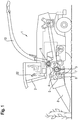
- Fig. 1 shows a schematic representation of a forage harvester 1.
- the body of the forage harvester 1 is shown cut open in its front part below a driver's cab 2 in order to be able to show internal, crop-processing assemblies of the forage harvester.
- One of these assemblies is a chopping drum assembly with a chopping drum 4 rotating about an axis 3 extending in the transverse direction of the vehicle.
- a conveying device 5 for harvested crop is upstream of the chopper drum assembly.
- the conveying device 5 comprises several pairs of rollers 6, 7, which each delimit a gap and are driven to rotate in opposite directions in order to feed the harvested material running through the gap to the chopping drum 4.
- the conveying device 5 in turn carries a harvesting header 6 which can be exchanged in adaptation to the plant material to be recovered.
- shredded crop is fed to a post-accelerator 9, which gives the shredded crop the necessary speed to pass through an ejection chute 10 and be transferred to an escort vehicle (not shown).
- Fig. 2 shows a front part of a frame 11 of the forage harvester 1 and the chopping drum assembly 12 mounted therein in a perspective view obliquely from the front.
- the frame 11 comprises two longitudinal members 13 extending essentially horizontally in the longitudinal direction of the vehicle, for example in the form of T or double T profiles, which are rigidly connected to one another by cross members (not visible in the figure) and on which an axle assembly 33 is a The front axle and steerable rear wheels of the forage harvester 1 are suspended.
- the front end of the side members 13 is in Fig. 2 hidden behind a pulley 14 driving the rotation of the chopping drum or a housing 15 surrounding the chopping drum.
- the housing 15 forms a tool holder for holding an exchangeable working tool, here the harvesting header 8.
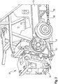
- Fig. 3 shows a side view of the frame 11 without the chopping drum assembly 12.
- the longitudinal beam 13 ends in a clamp mount 16 which is provided to receive a sleeve, not shown, through which the shaft of the chopping drum assembly 12 extends rotatably.
- the clamp mount 16 comprises a part 17 firmly connected to the longitudinal beam 13 in the form of a ring sector, the concavity 18 of which faces upwards so that the chopping drum assembly 12 can be stored in a stable manner during installation in or removal from the forage harvester 1 by inserting the sleeve in the concavity 18 is inserted.
- a second ring sector-shaped part 19 of the clamp mount 16 is connected to the frame part 13 via a joint 20.
- the front tips of the parts 17, 19 each have a bore in which a clamping screw 21 can be mounted.
- the clamping screw 21 is removed and the part 19 is folded up.
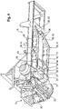
- Fig. 4 shows a view of the frame of the forage harvester 1 and the housing 15 of the chopping drum assembly 12 obliquely from below.
- a square adapter 30 is provided on the front of the housing 15 in order to mount the header 8 (not shown in this figure) or to couple a lifting machine to it to support the installation and removal of the chopping drum assembly 12 from the forage harvester 1.
- a hydraulic actuator 31 extends in the longitudinal direction of the vehicle under each of the side members 13. Pistons of the actuators 31 jointly engage a transverse bar 32 on the underside of the housing 15. The cylinders of the actuators 31 are each pivotably articulated on an abutment 34.
- the actuators 31 When the actuators 31 extend together, they pivot the housing 15 about the axis 3 and thereby possibly lift the header 8 mounted on the adapter 30.
- the abutments 34 of the two actuators 31 are each formed here by two legs 35 of a receiving part, between which the rear end of the actuator 31 is suspended.
- the receiving part is supported, on the one hand, on a housing of the axle assembly 33 and, on the other hand, on a girder 36 which extends backwards under each longitudinal beam 13 and is in turn anchored firmly to the longitudinal beam 13.
- the receiving part In order to absorb the pressure which is transmitted by the actuators 31 and acts essentially horizontally to the rear, the receiving part has a footplate 37 at its front end, which is connected to both legs 35 and is supported on a front side of the housing of the axle assembly 33, and on its rear end has a connecting section between the two legs 25 which is supported on the girder 36.
- the connecting section is connected to the joist 36 via a length-adjustable element 38 in order to ensure that the receiving part can be firmly connected to the housing and the joist without the receiving part, the joist, the longitudinal member and the housing being placed under bending stress .
- the pressure of the actuator 31, when it bears the weight of the header 8 during operation is distributed over the housing of the axle assembly 33 and the girder 36 according to their respective load capacity.
- Fig. 3 shows, with the aid of arrows, the transmission of the force exerted by the actuators 8 resulting from the weight of the header 8. Since this is distributed at the abutment 34 to the axle assembly 33 and the girder 36, both the axle assembly 33 and the longitudinal beam 13 are relieved. In particular, the reduction in the shear loads acting on the housing makes it possible to reduce the wall thickness and weight of the housing without deformation of the housing impairing the mobility of internal components of the axle assembly 33.
- the length-adjustable element 38 can, for example, comprise a threaded rod with a right-hand and a left-hand thread section, which each engage in a complementary nut on the side of the receiving part or on the side of the beam 36.
- the complementary nuts can be connected to the receiving part or to the beam 36 so as to be pivotable about an axis oriented in the transverse direction.
- the beams 36 each comprise a rod 39 which extends under one of the longitudinal beams 13 and which, viewed from above, follows the course of the longitudinal beam, and a plate 40 which is attached to the longitudinal beam 13 along its upper edge and to the rod 39 along its lower edge attached, for example welded, is. In order to minimize weight, the plate 40 can be perforated in places.
- the rod 40 has a front section 41, which extends essentially as an extension of the actuator 31 and parallel to the longitudinal beam 13, and a rear section 42 which rises obliquely towards the longitudinal beam 13 and is fastened at its rear end to the longitudinal beam 13.
- the rod 40 is prevented from deflecting a force transmitted by the actuator 31 by bending in the plane of the plate 40, i.e. essentially in the vertical.
- a further stabilizer body can be provided between the longitudinal beam 13 and the rod 40 in addition to the plate 40, which extends in a direction that is not parallel to the plane of the plate 40, here for example a strut 43, which is attached to the outer sides of the longitudinal beam 13 and the rod 39.
- connection points of the plate 40 and the strut 43 on the longitudinal beam 13 are spaced apart, but being closely adjacent on the rod 39, a rigid structure with an approximately triangular cross-section when viewed in the longitudinal direction is created, which reliably prevents the rod 39 from deflecting in the transverse direction.
- a transverse rod 44 which connects the front sections 41 of the rods 39 to one another, can also contribute to stiffening the beams 36.
Landscapes
- Life Sciences & Earth Sciences (AREA)
- Engineering & Computer Science (AREA)
- Environmental Sciences (AREA)
- Mechanical Engineering (AREA)
- Chemical & Material Sciences (AREA)
- Combustion & Propulsion (AREA)
- Transportation (AREA)
- Soil Sciences (AREA)
- Harvester Elements (AREA)
- Soil Working Implements (AREA)
Abstract
Description
- Die vorliegende Erfindung betrifft allgemein eine fahrbare landwirtschaftliche Maschine und insbesondere einen Feldhäcksler.
- Eine solche Maschine hat typischerweise ein Fahrgestell mit sich in Längsrichtung der Maschine erstreckenden Längsträgern, die durch Querträger miteinander verbunden sind und an denen eine Vorderachse, Hinterräder, ein Motor, ein Häckselwerk etc. montiert sind. Das Fahrgestell darf sich unter den im Betrieb darauf einwirkenden Biegemomenten nicht wesentlich verformen. Das für die nötige Stabilität erforderliche Gewicht des Fahrgestells erhöht den Kraftstoffverbrauch und begünstigt unerwünschte Bodenverdichtung.
- Werkzeuge für die Feldarbeit, die vorn oder hinten an die Maschine angekoppelt werden und deren Gewicht ganz oder zu einem großen Teil von der Maschine getragen wird, tragen erheblich zu den Biegemomenten bei, denen das Fahrgestell ausgesetzt ist, da ihr Gewicht mit einem langen Hebelarm einwirkt.
- Bei einem bekannten Feldhäcksler umfasst das Fahrgestell zwei Längsträger, an deren vorderen Enden jeweils ein Lager gebildet ist, in dem ein Halter für ein Werkzeug um eine in Querrichtung des Fahrgestells orientierte Achse schwenkbar gehalten ist. Unter den Längsträgern hindurch erstreckt sich eine Achsbaugruppe, an der die Vorderräder des Feldhäckslers drehbar gelagert sind. Eine Oberseite der Achsbaugruppe ist an den Längsträgern anliegend befestigt; an einer Unterseite der Achsbaugruppe ist ein Widerlager für ein Stellglied vorgesehen, das an dem Werkzeughalter angreift und das, um das Werkzeug stationär zu halten, in der Lage sein muss, ein Gegendrehmoment zu dem vom Werkzeug auf den Halter ausgeübten Drehmoment zu liefern. Die daraus am Widerlager resultierenden Kräfte erzeugen eine hohe Biegebelastung sowohl in der Achsbaugruppe als auch in den Längsträgern.
- Eine Aufgabe der vorliegenden Erfindung ist, einen Fahrgestellaufbau für eine landwirtschaftliche Maschine zu schaffen, die eine günstigere Verteilung der Biegekräfte im Fahrgestell erreicht und es so ermöglicht, eine erforderliche Steifigkeit des Fahrgestells bei relativ geringem Gewicht zu erreichen.
- Die Aufgabe wird gelöst, indem bei einer landwirtschaftlichen Maschine mit einem Fahrgestell, das wenigstens eine sich in Querrichtung der Maschine erstreckende Achsbaugruppe und wenigstens einen auf der Achsbaugruppe befestigten und sich in Längsrichtung der Maschine erstreckenden Längsträger umfasst, einem an ein Ende des Längsträgers angelenkten Werkzeughalter und einem Stellglied zum Schwenken des Werkzeughalters, das sich in der Längsrichtung zwischen einem Angriffspunkt am Werkzeughalter und einem am Fahrgestell festen Widerlager erstreckt, das Widerlager mit dem Längsträger nicht nur über die Achsbaugruppe verbunden ist, sondern auch über einen Unterzug, der sich an einer vom Werkzeughalter abgewandten Seite der Achsbaugruppe erstreckt.
- Der Unterzug kann insbesondere eine Stange umfassen, die sich mit zunehmender Entfernung von der Achsbaugruppe dem Längsträger annähert. Ein von dem Stellglied abgewandtes Ende kann unmittelbar an dem Längsträger verankert sein, um über das Stellglied übertragene Kräfte in den Längsträger einzuleiten.
- Ein dem Widerlager zugewandter Abschnitt der Stange kann sich in Verlängerung des Stellgliedes erstrecken; um die Stange im Wesentlichen nur auf Kompression zu belasten und die Biegebeanspruchung zu minimieren.
- Wenigstens ein Stabilisatorkörper kann sich geradlinig zwischen einem Verankerungspunkt an der Stange und einem Verankerungspunkt an dem Längsträger erstrecken. Um zu verhindern, dass die Stange der Belastung durch das Stellglied in einer Richtung fort vom Längsträger ausweicht, genügt, dass der Stabilisatorkörper zugbelastbar ist; Druck- und Biegebelastbarkeit des Stabilisatorkörpers sind zwar hilfreich, aber nicht zwingend notwendig.
- Indem wenigstens zwei Stabilisatorkörper vorgesehen sind, deren Verankerungspunkte an dem Längsträger in Querrichtung beabstandet sind, kann einer Neigung der Stange entgegengewirkt werden, einer in ihrer Längsrichtung wirkenden Druckbelastung in der Querrichtung auszuweichen.
- Eine steife Platte, die einen Zwischenraum zwischen der Stange und dem Längsträger ausfüllt und jeweils eine am Längsträger und eine an der Stange befestigte Kante aufweist, kann einen solchen Stabilisatorkörper bilden. Ein zweiter Stabilisatorkörper kann durch eine Strebe gebildet sein, die in einer zur Ebene der Platte nicht parallelen Richtung zwischen Längsträger und Stange erstreckt.
- Als von dem Werkzeughalter gehaltenes, insbesondere austauschbar gehaltenes, Werkzeug kommt insbesondere ein Erntevorsatz in Betracht.
- Wenn die landwirtschaftliche Maschine ein Feldhäcksler ist, kann der Werkzeughalter durch das Stellglied um eine Drehachse einer Häckseltrommel schwenkbar sein.
- Weitere Merkmale und Vorteile der Erfindung ergeben sich aus der nachfolgenden Beschreibung von Ausführungsbeispielen unter Bezugnahme auf die beigefügten Figuren. Es zeigen:
-
Fig. 1 eine schematische Darstellung eines Feldhäckslers; -
Fig. 2 eine Ansicht eines Rahmens des Feldhäckslers und einer in dem Rahmen montierten Häckseltrommelbaugruppe; -
Fig. 3 eine Seitenansicht des Rahmens; -
Fig. 4 eine Ansicht des Rahmens und eines Gehäuses der Häckseltrommelbaugruppe schräg von unten. -
Fig. 1 zeigt in schematischer Darstellung einen Feldhäcksler 1. Die Karosserie des Feldhäckslers 1 ist in ihrem Vorderteil, unterhalb einer Fahrerkabine 2, aufgeschnitten dargestellt, um interne, Erntegut verarbeitende Baugruppen des Feldhäckslers zeigen zu können. Eine dieser Baugruppen ist eine Häckseltrommelbaugruppe mit einer um eine sich in Fahrzeugquerrichtung erstreckende Achse 3 rotierenden Häckseltrommel 4. - Der Häckseltrommelbaugruppe ist eine Fördereinrichtung 5 für Erntegutvorgelagert. Die Fördereinrichtung 5 umfasst mehrere Walzenpaare 6, 7, die jeweils einen Spalt begrenzen und gegensinnig drehangetrieben sind, um das durch den Spalt hindurch laufende Erntegut der Häckseltrommel 4 zuzuführen.
- Die Fördereinrichtung 5 trägt wiederum einen in Anpassung an das zu bergende Pflanzenmaterial austauschbaren Erntevorsatz 6.
- In der Häckseltrommelbaugruppe zerkleinertes Erntegut wird einem Nachbeschleuniger 9 zugeführt, der dem zerkleinerten Erntegut die nötige Geschwindigkeit verleiht, um einen Auswurfkrümmer 10 zu durchlaufen und in ein (nicht dargestelltes) Begleitfahrzeug übergeladen zu werden.
-
Fig. 2 zeigt einen vorderen Teil eines Rahmens 11 des Feldhäckslers 1 und der darin montierten Häckseltrommelbaugruppe 12 in einer perspekti-vischen Ansicht schräg von vorn. Der Rahmen 11 umfasst zwei sich im Wesentlichen horizontal in Fahrzeuglängsrichtung erstreckende Längsträger 13, z.B. in Form von T- oder Doppel-T-Profilen, die untereinander durch (in der Fig. nicht sichtbare) Querträger starr verbunden sind und an denen eine Achsbaugruppe 33 einer Vorderachse sowie lenkbare Hinterräder des Feldhäckslers 1 aufgehängt sind. - Das vordere Ende der Längsträger 13 ist in
Fig. 2 hinter einer die Drehung der Häckseltrommel antreibenden Riemenscheibe 14 bzw. einem die Häckseltrommel umgebenden Gehäuse 15 verborgen. Das Gehäuse 15 bildet, wie später noch genauer erläutert wird, einen Werkzeughalter zum Halten eines austauschbaren Arbeitswerkzeugs, hier des Erntevorsatzes 8. -
Fig. 3 zeigt eine Seitenansicht des Rahmens 11 ohne die Häckseltrommelbaugruppe 12. Der Längsträger 13 endet in einer Klemmfassung 16, die vorgesehen ist, um eine nicht gezeigte Hülse aufzunehmen, durch die sich die Welle der Häckseltrommelbaugruppe 12 drehbar erstreckt. Die Klemmfassung 16 umfasst ein mit dem Längsträger 13 fest verbundenes Teil 17 in Form eines Ringsektors, dessen Konkavität 18 nach oben gewandt ist, so dass die Häckseltrommelbaugruppe 12 während des Einbaus im oder Ausbaus aus dem Feldhäcksler 1 stabil gelagert werden kann, indem die Hülse in die Konkavität 18 eingelegt wird. - Ein zweites ringsektorförmiges Teil 19 der Klemmfassung 16 ist mit dem Rahmenteil 13 über ein Gelenk 20 verbunden. Die vorderen Spitzen der Teile 17, 19 weisen jeweils eine Bohrung auf, in denen eine Spannschraube 21 montierbar ist. Um die Häckseltrommelbaugruppe 12 in die Konkavität 18 einlegen oder daraus entnehmen zu können, wird die Spannschraube 21 entfernt und das Teil 19 hochgeklappt.
-
Fig. 4 zeigt eine Ansicht des Rahmens des Feldhäckslers 1 und des Gehäuses 15 der Häckseltrommelbaugruppe 12 schräg von unten. Ein viereckiger Adapter 30 an der Vorderseite des Gehäuses 15 ist vorgesehen, um daran den in dieser Figur nicht dargestellten Erntevorsatz 8 zu montieren oder um daran eine Hebemaschine zum Unterstützen von Ein- und Ausbau der Häckseltrommelbaugruppe 12 aus dem Feldhäcksler 1 anzukoppeln. Unter jedem der Längsträger 13 erstreckt sich ein hydraulisches Stellglied 31 in Fahrzeuglängsrichtung. Kolben der Stellglieder 31 greifen gemeinsam an einem Querbalken 32 an der Unterseite des Gehäuses 15 an. Zylinder der Stellglieder 31 sind jeweils an einem Widerlager 34 schwenkbar angelenkt. - Indem die Stellglieder 31 gemeinsam ausfahren, schwenken sie das Gehäuse 15 um die Achse 3 und heben dadurch ggf. den an dem Adapter 30 montierten Erntevorsatz 8 an.
- Die Widerlager 34 der beiden Stellglieder 31 sind hier jeweils durch zwei Schenkel 35 eines Aufnahmeteils gebildet, zwischen denen das hintere Ende des Stellgliedes 31 aufgehängt ist. Das Aufnahmeteil ist einerseits an einem Gehäuse der Achsbaugruppe 33 und andererseits an einem sich unter jedem Längsträger 13 nach hinten erstreckenden und seinerseits an dem Längsträger 13 fest verankerten Unterzug 36 abgestützt.
- Um von den von den Stellgliedern 31 übertragenen, im Wesentlichen horizontal nach hinten wirkenden Druck abzufangen, hat das Aufnahmeteil an seinem vorderen Ende eine Fußplatte 37, die mit beiden Schenkeln 35 verbunden ist und sich an einer Vorderseite des Gehäuses der Achsbaugruppe 33 abstützt, und an seinem hinteren Ende einen Verbindungsabschnitt zwischen den beiden Schenkeln 25, der sich am Unterzug 36 abstützt. Der Verbindungsabschnitt ist mit dem Unterzug 36 über ein längenjustierbares Element 38 verbunden, um sicherzustellen, dass das Aufnahmeteil mit dem Gehäuse und dem Unterzug fest verbunden werden kann, ohne dass sich dadurch das Aufnahmeteil, der Unterzug, der Längsträger und das Gehäuse gegenseitig unter Biegespannung setzen. So verteilt sich der Druck des Stellgliedes 31, wenn dieses im Betrieb das Gewicht des Erntevorsatzes 8 trägt, auf das Gehäuse der Achsbaugruppe 33 und den Unterzug 36 entsprechend ihrer jeweiligen Belastbarkeit.
-
Fig. 3 zeigt anhand von Pfeilen die Übertragung der aus dem Gewicht des Erntevorsatzes 8 resultierenden, von den Stellgliedern 8 ausgeübten Kraft. Indem sich diese am Widerlager 34 auf die Achsbaugruppe 33 und den Unterzug 36 verteilt, werden sowohl die Achsbaugruppe 33 als auch der Längsträger 13 entlastet. Insbesondere die Verringerung der auf das Gehäuse einwirkenden Scherbelastungen erlaubt es, Wandstärke und Gewicht des Gehäuses zu vermindern, ohne dass eine Deformation des Gehäuses zu einer Beeinträchtigung der Beweglichkeit innerer Komponenten der Achsbaugruppe 33 führt. - Das längenjustierbare Element 38 kann z.B. eine Gewindestange mit einem Rechts- und einem Linksgewindeabschnitt umfassen, die jeweils in eine komplementäre Mutter auf Seiten des Aufnahmeteils bzw. auf Seiten des Unterzugs 36 eingreifen. Um Fertigungstoleranzen auszugleichen, können die komplementären Muttern mit dem Aufnahmeteil bzw. mit dem Unterzug 36 um eine in Querrichtung orientierte Achse schwenkbar verbunden sein.
- Die Unterzüge 36 umfassen jeweils eine Stange 39, die sich unter einem der Längsträger 13 erstreckt und die, von oben gesehen, dem Verlauf des Längsträgers folgt, und eine Platte 40, die entlang ihrer Oberkante am Längsträger 13 und entlang ihrer Unterkante an der Stange 39 befestigt, z.B. verschweißt, ist. Zur Gewichtsminimierung kann die Platte 40 stellenweise durchbrochen sein. Die Stange 40 hat einen vorderen Abschnitt 41, der sich im Wesentlichen in Verlängerung des Stellglieds 31 und parallel zum Längsträger 13 erstreckt, und einen hinteren Abschnitt 42, der zum Längsträger 13 hin schräg ansteigt und an seinem hinteren Ende am Längsträger 13 befestigt ist. Indem insbesondere der vordere Abschnitt 41 über die Platte 40 mit dem Längsträger 13 verbunden ist, wird verhindert, dass die Stange 40 einer vom Stellglied 31 übertragenen Kraft durch eine Verbiegung in der Ebene der Platte 40, d.h. im Wesentlichen in der Vertikalen, ausweicht. Um ein Ausweichen auch in der Querrichtung zu unterbinden, kann neben der Platte 40 noch ein weiterer Stabilisatorkörper zwischen dem Längsträger 13 und der Stange 40 vorgesehen sein, der sich in einer zur Ebene der Platte 40 nicht parallelen Richtung erstreckt, hier z.B. eine Strebe 43, die an Außenseiten des Längsträgers 13 und der Stange 39 befestigt ist. Indem Verbindungspunkte der Platte 40 und der Strebe 43 am Längsträger 13 beabstandet, an der Stange 39 aber eng benachbart wird, wird eine biegesteife Struktur von in der Längsrichtung betrachtet in etwa dreieckigem Querschnitt geschaffen, die ein Ausweichen der Stange 39 in Querrichtung sicher unterbindet.
- Zur Versteifung der Unterzüge 36 kann ferner eine Querstange 44 beitragen, die die vorderen Abschnitte 41 der Stangen 39 untereinander verbindet.
-
- 1
- Feldhäcksler
- 2
- Fahrerkabine
- 3
- Achse
- 4
- Häckseltrommel
- 5
- Fördereinrichtung
- 6
- Walzenpaar
- 7
- Walzenpaar
- 8
- Erntevorsatz
- 9
- Nachbeschleuniger
- 10
- Auswurfkrümmer
- 11
- Rahmen
- 12
- Häckseltrommelbaugruppe
- 13
- Längsträger
- 14
- Riemenscheibe
- 15
- Gehäuse/Werkzeughalter
- 16
- Klemmfassung
- 17
- Teil von 16
- 18
- Konkavität
- 19
- Teil von 16
- 20
- Gelenk
- 21
- Spannschraube
- 30
- Adapter
- 31
- Stellglied
- 32
- Querbalken
- 33
- Achsbaugruppe
- 34
- Widerlager
- 35
- Schenkel
- 36
- Unterzug
- 37
- Fußplatte
- 38
- längenjustierbares Element
- 39
- Stange
- 40
- Platte
- 41
- vorderer Abschnitt
- 42
- hinterer Abschnitt
- 43
- Strebe
- 44.
- Querstange
Claims (11)
- Landwirtschaftliche Maschine mit einem Fahrgestell, das eine sich in Querrichtung der Maschine erstreckende Achsbaugruppe (33) und wenigstens einen auf der Achsbaugruppe (33) befestigten und sich in Längsrichtung der Maschine erstreckenden Längsträger (13) umfasst, einem an ein Ende des Längsträgers (13) angelenkten Werkzeughalter (15) und einem Stellglied (31) zum Schwenken des Werkzeughalters (15), das sich in der Längsrichtung zwischen einem Angriffspunkt am Werkzeughalter (15) und einem am Fahrgestell festen Widerlager (34) erstreckt, das mit dem Längsträger (13) über die Achsbaugruppe (33) verbunden ist, dadurch gekennzeichnet, dass das Widerlager (34) mit dem Längsträger (13) ferner über einen Unterzug (36) verbunden ist, der sich an einer vom Werkzeughalter (15) abgewandten Seite der Achsbaugruppe (33) erstreckt.
- Landwirtschaftliche Maschine nach Anspruch 2 oder 3, dadurch gekennzeichnet, dass das Widerlager (34) mit dem Unterzug (36) über ein längenjustierbares Element (38) verbunden ist.
- Landwirtschaftliche Maschine nach Anspruch 1 oder 2, dadurch gekennzeichnet, dass der Unterzug (36) eine Stange (39) umfasst, die sich mit zunehmender Entfernung von der Achsbaugruppe (33) dem Längsträger (13) annähert.
- Landwirtschaftliche Maschine nach Anspruch 3, dadurch gekennzeichnet, dass ein dem Widerlager (34) zugewandter Abschnitt (41) der Stange (39) sich in Verlängerung des Stellgliedes (31) erstreckt.
- Landwirtschaftliche Maschine nach Anspruch 3 oder 4, dadurch gekennzeichnet, dass wenigstens ein Stabilisatorkörper (40, 43) )sich geradlinig zwischen einem Verankerungspunkt an der Stange (39) und einem Verankerungspunkt an dem Längsträger (13) erstreckt.
- Landwirtschaftliche Maschine nach Anspruch 3, 4 oder 5, dadurch gekennzeichnet, dass wenigstens zwei Stabilisatorkörper (40, 43) vorgesehen sind, deren Verankerungspunkte an dem Längsträger (13) in Querrichtung beabstandet sind.
- Landwirtschaftliche Maschine nach einem der Ansprüche 3 bis 6, dadurch gekennzeichnet, dass ein vom Widerlager (34) abgewandtes Ende der Stange (39) unmittelbar an dem Längsträger (13) befestigt ist.
- Landwirtschaftliche Maschine nach einem der Ansprüche 3 bis 7, dadurch gekennzeichnet, dass eine steife Platte (40) einen Zwischenraum zwischen der Stange (39) und dem Längsträger (13) ausfüllt und jeweils eine am Längsträger (13) und eine an der Stange (39 befestigte Kante aufweist.
- Landwirtschaftliche Maschine nach einem der vorhergehenden Ansprüche, dadurch gekennzeichnet, dass zwei Längsträger (13) an entgegengesetzten Seiten des Rahmens vorgesehen sind, und dass jedem der Längsträger (13) ein Stellglied (31) zum Schwenken des Werkzeughalters (15) zugeordnet ist.
- Landwirtschaftliche Maschine nach einem der vorhergehenden Ansprüche, dadurch gekennzeichnet, dass der Werkzeughalter (15) eingerichtet ist, als Werkzeug einen Erntevorsatz (8) zu tragen.
- Landwirtschaftliche Maschine nach einem der vorhergehenden Ansprüche, dadurch gekennzeichnet, dass sie ein Feldhäcksler ist und der Werkzeughalter (15) durch das Stellglied (31) um eine Drehachse (3) einer Häckseltrommel schwenkbar ist.
Applications Claiming Priority (1)
| Application Number | Priority Date | Filing Date | Title |
|---|---|---|---|
| DE102020115945.5A DE102020115945A1 (de) | 2020-06-17 | 2020-06-17 | Landwirtschaftliche Maschine |
Publications (2)
| Publication Number | Publication Date |
|---|---|
| EP3925422A1 true EP3925422A1 (de) | 2021-12-22 |
| EP3925422B1 EP3925422B1 (de) | 2023-04-19 |
Family
ID=75674647
Family Applications (1)
| Application Number | Title | Priority Date | Filing Date |
|---|---|---|---|
| EP21170336.8A Active EP3925422B1 (de) | 2020-06-17 | 2021-04-26 | Landwirtschaftliche maschine |
Country Status (2)
| Country | Link |
|---|---|
| EP (1) | EP3925422B1 (de) |
| DE (1) | DE102020115945A1 (de) |
Families Citing this family (1)
| Publication number | Priority date | Publication date | Assignee | Title |
|---|---|---|---|---|
| DE102023104613A1 (de) | 2023-02-24 | 2024-08-29 | Deere & Company | Feldhäcksler mit einem tragenden Rahmen |
Citations (3)
| Publication number | Priority date | Publication date | Assignee | Title |
|---|---|---|---|---|
| DE10011498B4 (de) * | 2000-03-09 | 2004-12-30 | Case Harvesting Systems Gmbh | Vorrichtung zur Bodenkopierung für Vorsatzgeräte an Erntemaschinen |
| EP1927277A1 (de) * | 2006-11-30 | 2008-06-04 | CLAAS Selbstfahrende Erntemaschinen GmbH | Landwirtschaftliche Erntemaschine mit Überladeeinrichtung |
| DE102008049130A1 (de) * | 2008-09-26 | 2010-04-01 | Claas Selbstfahrende Erntemaschinen Gmbh | Landwirtschaftliche Erntemaschine |
-
2020
- 2020-06-17 DE DE102020115945.5A patent/DE102020115945A1/de not_active Withdrawn
-
2021
- 2021-04-26 EP EP21170336.8A patent/EP3925422B1/de active Active
Patent Citations (3)
| Publication number | Priority date | Publication date | Assignee | Title |
|---|---|---|---|---|
| DE10011498B4 (de) * | 2000-03-09 | 2004-12-30 | Case Harvesting Systems Gmbh | Vorrichtung zur Bodenkopierung für Vorsatzgeräte an Erntemaschinen |
| EP1927277A1 (de) * | 2006-11-30 | 2008-06-04 | CLAAS Selbstfahrende Erntemaschinen GmbH | Landwirtschaftliche Erntemaschine mit Überladeeinrichtung |
| DE102008049130A1 (de) * | 2008-09-26 | 2010-04-01 | Claas Selbstfahrende Erntemaschinen Gmbh | Landwirtschaftliche Erntemaschine |
Also Published As
| Publication number | Publication date |
|---|---|
| DE102020115945A1 (de) | 2021-12-23 |
| EP3925422B1 (de) | 2023-04-19 |
Similar Documents
| Publication | Publication Date | Title |
|---|---|---|
| EP1389413B1 (de) | Anlenkung eines Seitenmähwerks und seiner Zusatzeinrichtung an ein Tragwerk zur Ankopplung an einen Traktor oder an ein Trägerfahrzeug | |
| DD273375A5 (de) | Selbstfahrender maehdrescher mit zweigeteiltem schneidwerk | |
| BE1027572B1 (de) | Konditionierwalzenzusammenbau | |
| DE2355792A1 (de) | Dreschkorb-verstellvorrichtung fuer maehdrescher | |
| EP3925422B1 (de) | Landwirtschaftliche maschine | |
| EP0832554A2 (de) | Mähdrescher | |
| EP2489254A1 (de) | Einzugsvorrichtung für einen Feldhäcksler | |
| EP2592042A1 (de) | Trageinrichtung für Lastaufnahmemittel sowie Adapter für Trageinrichtung | |
| DE102021118849B3 (de) | Portalschneidwerk | |
| EP0176057A2 (de) | Zerkleinerungsvorrichtung für organische Abfallmaterialien | |
| DE102007035796A1 (de) | Vorrichtung zur Arretierung eines Wagens zur Abstützung eines Erntevorsatzes bei einer Straßenfahrt an dem Erntevorsatz | |
| DE3330195A1 (de) | Zufuehr- und haeckseleinrichtung | |
| DE3233560C1 (de) | Frontmähwerk | |
| DE102007035744B4 (de) | Kombination aus einem Erntevorsatz und einem Wagen zur Abstützung des Erntevorsatzes | |
| EP1154681A1 (de) | Mähaufbereiter | |
| EP4309487B1 (de) | Feldhäcksler mit einer rahmenbaugruppe | |
| EP0795265A1 (de) | Anhängevorrichtung | |
| EP2011383A1 (de) | Erntemaschine mit Schneidwerk | |
| EP3753385A1 (de) | Tragwerk für die verbindung zweier landwirtschaftlicher anbaugeräte mit einem schlepper sowie landwirtschaftliches anbaugerät | |
| DE102020132157B4 (de) | Einteiliges Basiselement für einen Auswurfkrümmer eines Feldhäckslers | |
| DE102023104613A1 (de) | Feldhäcksler mit einem tragenden Rahmen | |
| BE1031829B1 (de) | Heckgewichtzusammenbau zur Anbringung an einem Feldhäcksler | |
| DE202019004950U1 (de) | Flächen-Bearbeitungseinrichtung für eine Zugmaschine | |
| EP4487674B1 (de) | Vorsatzgerät | |
| DE102019215142A1 (de) | Feldhäcksler mit getrennt vom Übergangsgehäuse abgestütztem Auswurfkrümmer |
Legal Events
| Date | Code | Title | Description |
|---|---|---|---|
| PUAI | Public reference made under article 153(3) epc to a published international application that has entered the european phase |
Free format text: ORIGINAL CODE: 0009012 |
|
| STAA | Information on the status of an ep patent application or granted ep patent |
Free format text: STATUS: THE APPLICATION HAS BEEN PUBLISHED |
|
| AK | Designated contracting states |
Kind code of ref document: A1 Designated state(s): AL AT BE BG CH CY CZ DE DK EE ES FI FR GB GR HR HU IE IS IT LI LT LU LV MC MK MT NL NO PL PT RO RS SE SI SK SM TR |
|
| B565 | Issuance of search results under rule 164(2) epc |
Effective date: 20211025 |
|
| STAA | Information on the status of an ep patent application or granted ep patent |
Free format text: STATUS: REQUEST FOR EXAMINATION WAS MADE |
|
| 17P | Request for examination filed |
Effective date: 20220622 |
|
| RBV | Designated contracting states (corrected) |
Designated state(s): AL AT BE BG CH CY CZ DE DK EE ES FI FR GB GR HR HU IE IS IT LI LT LU LV MC MK MT NL NO PL PT RO RS SE SI SK SM TR |
|
| RIC1 | Information provided on ipc code assigned before grant |
Ipc: B62D 21/18 20060101ALI20221021BHEP Ipc: A01F 29/01 20060101ALI20221021BHEP Ipc: A01B 63/108 20060101AFI20221021BHEP |
|
| GRAP | Despatch of communication of intention to grant a patent |
Free format text: ORIGINAL CODE: EPIDOSNIGR1 |
|
| STAA | Information on the status of an ep patent application or granted ep patent |
Free format text: STATUS: GRANT OF PATENT IS INTENDED |
|
| INTG | Intention to grant announced |
Effective date: 20221215 |
|
| GRAS | Grant fee paid |
Free format text: ORIGINAL CODE: EPIDOSNIGR3 |
|
| GRAA | (expected) grant |
Free format text: ORIGINAL CODE: 0009210 |
|
| STAA | Information on the status of an ep patent application or granted ep patent |
Free format text: STATUS: THE PATENT HAS BEEN GRANTED |
|
| AK | Designated contracting states |
Kind code of ref document: B1 Designated state(s): AL AT BE BG CH CY CZ DE DK EE ES FI FR GB GR HR HU IE IS IT LI LT LU LV MC MK MT NL NO PL PT RO RS SE SI SK SM TR |
|
| REG | Reference to a national code |
Ref country code: GB Ref legal event code: FG4D Free format text: NOT ENGLISH |
|
| REG | Reference to a national code |
Ref country code: DE Ref legal event code: R096 Ref document number: 502021000581 Country of ref document: DE |
|
| REG | Reference to a national code |
Ref country code: CH Ref legal event code: EP |
|
| REG | Reference to a national code |
Ref country code: IE Ref legal event code: FG4D Free format text: LANGUAGE OF EP DOCUMENT: GERMAN |
|
| REG | Reference to a national code |
Ref country code: AT Ref legal event code: REF Ref document number: 1560528 Country of ref document: AT Kind code of ref document: T Effective date: 20230515 |
|
| P01 | Opt-out of the competence of the unified patent court (upc) registered |
Effective date: 20230516 |
|
| REG | Reference to a national code |
Ref country code: LT Ref legal event code: MG9D |
|
| REG | Reference to a national code |
Ref country code: NL Ref legal event code: MP Effective date: 20230419 |
|
| PG25 | Lapsed in a contracting state [announced via postgrant information from national office to epo] |
Ref country code: NL Free format text: LAPSE BECAUSE OF FAILURE TO SUBMIT A TRANSLATION OF THE DESCRIPTION OR TO PAY THE FEE WITHIN THE PRESCRIBED TIME-LIMIT Effective date: 20230419 |
|
| PG25 | Lapsed in a contracting state [announced via postgrant information from national office to epo] |
Ref country code: SE Free format text: LAPSE BECAUSE OF FAILURE TO SUBMIT A TRANSLATION OF THE DESCRIPTION OR TO PAY THE FEE WITHIN THE PRESCRIBED TIME-LIMIT Effective date: 20230419 Ref country code: PT Free format text: LAPSE BECAUSE OF FAILURE TO SUBMIT A TRANSLATION OF THE DESCRIPTION OR TO PAY THE FEE WITHIN THE PRESCRIBED TIME-LIMIT Effective date: 20230821 Ref country code: NO Free format text: LAPSE BECAUSE OF FAILURE TO SUBMIT A TRANSLATION OF THE DESCRIPTION OR TO PAY THE FEE WITHIN THE PRESCRIBED TIME-LIMIT Effective date: 20230719 Ref country code: ES Free format text: LAPSE BECAUSE OF FAILURE TO SUBMIT A TRANSLATION OF THE DESCRIPTION OR TO PAY THE FEE WITHIN THE PRESCRIBED TIME-LIMIT Effective date: 20230419 |
|
| PG25 | Lapsed in a contracting state [announced via postgrant information from national office to epo] |
Ref country code: RS Free format text: LAPSE BECAUSE OF FAILURE TO SUBMIT A TRANSLATION OF THE DESCRIPTION OR TO PAY THE FEE WITHIN THE PRESCRIBED TIME-LIMIT Effective date: 20230419 Ref country code: PL Free format text: LAPSE BECAUSE OF FAILURE TO SUBMIT A TRANSLATION OF THE DESCRIPTION OR TO PAY THE FEE WITHIN THE PRESCRIBED TIME-LIMIT Effective date: 20230419 Ref country code: LV Free format text: LAPSE BECAUSE OF FAILURE TO SUBMIT A TRANSLATION OF THE DESCRIPTION OR TO PAY THE FEE WITHIN THE PRESCRIBED TIME-LIMIT Effective date: 20230419 Ref country code: LT Free format text: LAPSE BECAUSE OF FAILURE TO SUBMIT A TRANSLATION OF THE DESCRIPTION OR TO PAY THE FEE WITHIN THE PRESCRIBED TIME-LIMIT Effective date: 20230419 Ref country code: IS Free format text: LAPSE BECAUSE OF FAILURE TO SUBMIT A TRANSLATION OF THE DESCRIPTION OR TO PAY THE FEE WITHIN THE PRESCRIBED TIME-LIMIT Effective date: 20230819 Ref country code: HR Free format text: LAPSE BECAUSE OF FAILURE TO SUBMIT A TRANSLATION OF THE DESCRIPTION OR TO PAY THE FEE WITHIN THE PRESCRIBED TIME-LIMIT Effective date: 20230419 Ref country code: GR Free format text: LAPSE BECAUSE OF FAILURE TO SUBMIT A TRANSLATION OF THE DESCRIPTION OR TO PAY THE FEE WITHIN THE PRESCRIBED TIME-LIMIT Effective date: 20230720 Ref country code: AL Free format text: LAPSE BECAUSE OF FAILURE TO SUBMIT A TRANSLATION OF THE DESCRIPTION OR TO PAY THE FEE WITHIN THE PRESCRIBED TIME-LIMIT Effective date: 20230419 |
|
| PG25 | Lapsed in a contracting state [announced via postgrant information from national office to epo] |
Ref country code: LU Free format text: LAPSE BECAUSE OF NON-PAYMENT OF DUE FEES Effective date: 20230426 Ref country code: FI Free format text: LAPSE BECAUSE OF FAILURE TO SUBMIT A TRANSLATION OF THE DESCRIPTION OR TO PAY THE FEE WITHIN THE PRESCRIBED TIME-LIMIT Effective date: 20230419 |
|
| PG25 | Lapsed in a contracting state [announced via postgrant information from national office to epo] |
Ref country code: SK Free format text: LAPSE BECAUSE OF FAILURE TO SUBMIT A TRANSLATION OF THE DESCRIPTION OR TO PAY THE FEE WITHIN THE PRESCRIBED TIME-LIMIT Effective date: 20230419 |
|
| PG25 | Lapsed in a contracting state [announced via postgrant information from national office to epo] |
Ref country code: MC Free format text: LAPSE BECAUSE OF FAILURE TO SUBMIT A TRANSLATION OF THE DESCRIPTION OR TO PAY THE FEE WITHIN THE PRESCRIBED TIME-LIMIT Effective date: 20230419 |
|
| REG | Reference to a national code |
Ref country code: DE Ref legal event code: R097 Ref document number: 502021000581 Country of ref document: DE |
|
| PG25 | Lapsed in a contracting state [announced via postgrant information from national office to epo] |
Ref country code: SM Free format text: LAPSE BECAUSE OF FAILURE TO SUBMIT A TRANSLATION OF THE DESCRIPTION OR TO PAY THE FEE WITHIN THE PRESCRIBED TIME-LIMIT Effective date: 20230419 Ref country code: SK Free format text: LAPSE BECAUSE OF FAILURE TO SUBMIT A TRANSLATION OF THE DESCRIPTION OR TO PAY THE FEE WITHIN THE PRESCRIBED TIME-LIMIT Effective date: 20230419 Ref country code: RO Free format text: LAPSE BECAUSE OF FAILURE TO SUBMIT A TRANSLATION OF THE DESCRIPTION OR TO PAY THE FEE WITHIN THE PRESCRIBED TIME-LIMIT Effective date: 20230419 Ref country code: MC Free format text: LAPSE BECAUSE OF FAILURE TO SUBMIT A TRANSLATION OF THE DESCRIPTION OR TO PAY THE FEE WITHIN THE PRESCRIBED TIME-LIMIT Effective date: 20230419 Ref country code: EE Free format text: LAPSE BECAUSE OF FAILURE TO SUBMIT A TRANSLATION OF THE DESCRIPTION OR TO PAY THE FEE WITHIN THE PRESCRIBED TIME-LIMIT Effective date: 20230419 Ref country code: DK Free format text: LAPSE BECAUSE OF FAILURE TO SUBMIT A TRANSLATION OF THE DESCRIPTION OR TO PAY THE FEE WITHIN THE PRESCRIBED TIME-LIMIT Effective date: 20230419 Ref country code: CZ Free format text: LAPSE BECAUSE OF FAILURE TO SUBMIT A TRANSLATION OF THE DESCRIPTION OR TO PAY THE FEE WITHIN THE PRESCRIBED TIME-LIMIT Effective date: 20230419 |
|
| REG | Reference to a national code |
Ref country code: IE Ref legal event code: MM4A |
|
| PLBE | No opposition filed within time limit |
Free format text: ORIGINAL CODE: 0009261 |
|
| STAA | Information on the status of an ep patent application or granted ep patent |
Free format text: STATUS: NO OPPOSITION FILED WITHIN TIME LIMIT |
|
| 26N | No opposition filed |
Effective date: 20240122 |
|
| PG25 | Lapsed in a contracting state [announced via postgrant information from national office to epo] |
Ref country code: IE Free format text: LAPSE BECAUSE OF NON-PAYMENT OF DUE FEES Effective date: 20230426 |
|
| PG25 | Lapsed in a contracting state [announced via postgrant information from national office to epo] |
Ref country code: IE Free format text: LAPSE BECAUSE OF NON-PAYMENT OF DUE FEES Effective date: 20230426 |
|
| PG25 | Lapsed in a contracting state [announced via postgrant information from national office to epo] |
Ref country code: SI Free format text: LAPSE BECAUSE OF FAILURE TO SUBMIT A TRANSLATION OF THE DESCRIPTION OR TO PAY THE FEE WITHIN THE PRESCRIBED TIME-LIMIT Effective date: 20230419 |
|
| PG25 | Lapsed in a contracting state [announced via postgrant information from national office to epo] |
Ref country code: SI Free format text: LAPSE BECAUSE OF FAILURE TO SUBMIT A TRANSLATION OF THE DESCRIPTION OR TO PAY THE FEE WITHIN THE PRESCRIBED TIME-LIMIT Effective date: 20230419 Ref country code: IT Free format text: LAPSE BECAUSE OF FAILURE TO SUBMIT A TRANSLATION OF THE DESCRIPTION OR TO PAY THE FEE WITHIN THE PRESCRIBED TIME-LIMIT Effective date: 20230419 Ref country code: FR Free format text: LAPSE BECAUSE OF NON-PAYMENT OF DUE FEES Effective date: 20230619 |
|
| PG25 | Lapsed in a contracting state [announced via postgrant information from national office to epo] |
Ref country code: BG Free format text: LAPSE BECAUSE OF FAILURE TO SUBMIT A TRANSLATION OF THE DESCRIPTION OR TO PAY THE FEE WITHIN THE PRESCRIBED TIME-LIMIT Effective date: 20230419 |
|
| PG25 | Lapsed in a contracting state [announced via postgrant information from national office to epo] |
Ref country code: BG Free format text: LAPSE BECAUSE OF FAILURE TO SUBMIT A TRANSLATION OF THE DESCRIPTION OR TO PAY THE FEE WITHIN THE PRESCRIBED TIME-LIMIT Effective date: 20230419 |
|
| REG | Reference to a national code |
Ref country code: CH Ref legal event code: PL |
|
| PG25 | Lapsed in a contracting state [announced via postgrant information from national office to epo] |
Ref country code: CH Free format text: LAPSE BECAUSE OF NON-PAYMENT OF DUE FEES Effective date: 20240430 |
|
| PGFP | Annual fee paid to national office [announced via postgrant information from national office to epo] |
Ref country code: DE Payment date: 20250422 Year of fee payment: 5 |
|
| PGFP | Annual fee paid to national office [announced via postgrant information from national office to epo] |
Ref country code: BE Payment date: 20250418 Year of fee payment: 5 |
|
| PGFP | Annual fee paid to national office [announced via postgrant information from national office to epo] |
Ref country code: AT Payment date: 20250721 Year of fee payment: 5 |
|
| PG25 | Lapsed in a contracting state [announced via postgrant information from national office to epo] |
Ref country code: CY Free format text: LAPSE BECAUSE OF FAILURE TO SUBMIT A TRANSLATION OF THE DESCRIPTION OR TO PAY THE FEE WITHIN THE PRESCRIBED TIME-LIMIT; INVALID AB INITIO Effective date: 20210426 |
|
| PG25 | Lapsed in a contracting state [announced via postgrant information from national office to epo] |
Ref country code: HU Free format text: LAPSE BECAUSE OF FAILURE TO SUBMIT A TRANSLATION OF THE DESCRIPTION OR TO PAY THE FEE WITHIN THE PRESCRIBED TIME-LIMIT; INVALID AB INITIO Effective date: 20210426 |
|
| PG25 | Lapsed in a contracting state [announced via postgrant information from national office to epo] |
Ref country code: TR Free format text: LAPSE BECAUSE OF FAILURE TO SUBMIT A TRANSLATION OF THE DESCRIPTION OR TO PAY THE FEE WITHIN THE PRESCRIBED TIME-LIMIT Effective date: 20230419 |
|
| GBPC | Gb: european patent ceased through non-payment of renewal fee |
Effective date: 20250426 |
|
| PG25 | Lapsed in a contracting state [announced via postgrant information from national office to epo] |
Ref country code: GB Free format text: LAPSE BECAUSE OF NON-PAYMENT OF DUE FEES Effective date: 20250426 |