EP3922498B1 - An expansion tank for a vehicle with dual cooling lines, a coolant system and a method for filling the expansion tank - Google Patents
An expansion tank for a vehicle with dual cooling lines, a coolant system and a method for filling the expansion tank Download PDFInfo
- Publication number
- EP3922498B1 EP3922498B1 EP20179478.1A EP20179478A EP3922498B1 EP 3922498 B1 EP3922498 B1 EP 3922498B1 EP 20179478 A EP20179478 A EP 20179478A EP 3922498 B1 EP3922498 B1 EP 3922498B1
- Authority
- EP
- European Patent Office
- Prior art keywords
- expansion tank
- fluid
- chamber
- pressure
- cooling
- Prior art date
- Legal status (The legal status is an assumption and is not a legal conclusion. Google has not performed a legal analysis and makes no representation as to the accuracy of the status listed.)
- Active
Links
- 238000001816 cooling Methods 0.000 title claims description 103
- 239000002826 coolant Substances 0.000 title claims description 17
- 238000000034 method Methods 0.000 title claims description 12
- 230000009977 dual effect Effects 0.000 title claims description 9
- 239000012530 fluid Substances 0.000 claims description 95
- 239000007788 liquid Substances 0.000 claims description 19
- 239000012809 cooling fluid Substances 0.000 claims description 6
- 238000002485 combustion reaction Methods 0.000 claims description 5
- XLYOFNOQVPJJNP-UHFFFAOYSA-N water Substances O XLYOFNOQVPJJNP-UHFFFAOYSA-N 0.000 claims description 4
- 239000012080 ambient air Substances 0.000 claims description 3
- 238000007710 freezing Methods 0.000 claims description 3
- 238000004891 communication Methods 0.000 description 2
- 239000000110 cooling liquid Substances 0.000 description 2
- 238000013461 design Methods 0.000 description 2
- 238000012986 modification Methods 0.000 description 2
- 230000004048 modification Effects 0.000 description 2
- 239000003570 air Substances 0.000 description 1
- 230000007812 deficiency Effects 0.000 description 1
- 230000000694 effects Effects 0.000 description 1
- 230000007613 environmental effect Effects 0.000 description 1
- 239000000446 fuel Substances 0.000 description 1
- 238000013021 overheating Methods 0.000 description 1
Images


Classifications
-
- B—PERFORMING OPERATIONS; TRANSPORTING
- B60—VEHICLES IN GENERAL
- B60K—ARRANGEMENT OR MOUNTING OF PROPULSION UNITS OR OF TRANSMISSIONS IN VEHICLES; ARRANGEMENT OR MOUNTING OF PLURAL DIVERSE PRIME-MOVERS IN VEHICLES; AUXILIARY DRIVES FOR VEHICLES; INSTRUMENTATION OR DASHBOARDS FOR VEHICLES; ARRANGEMENTS IN CONNECTION WITH COOLING, AIR INTAKE, GAS EXHAUST OR FUEL SUPPLY OF PROPULSION UNITS IN VEHICLES
- B60K11/00—Arrangement in connection with cooling of propulsion units
- B60K11/02—Arrangement in connection with cooling of propulsion units with liquid cooling
-
- F—MECHANICAL ENGINEERING; LIGHTING; HEATING; WEAPONS; BLASTING
- F01—MACHINES OR ENGINES IN GENERAL; ENGINE PLANTS IN GENERAL; STEAM ENGINES
- F01P—COOLING OF MACHINES OR ENGINES IN GENERAL; COOLING OF INTERNAL-COMBUSTION ENGINES
- F01P11/00—Component parts, details, or accessories not provided for in, or of interest apart from, groups F01P1/00 - F01P9/00
- F01P11/02—Liquid-coolant filling, overflow, venting, or draining devices
- F01P11/029—Expansion reservoirs
-
- F—MECHANICAL ENGINEERING; LIGHTING; HEATING; WEAPONS; BLASTING
- F01—MACHINES OR ENGINES IN GENERAL; ENGINE PLANTS IN GENERAL; STEAM ENGINES
- F01P—COOLING OF MACHINES OR ENGINES IN GENERAL; COOLING OF INTERNAL-COMBUSTION ENGINES
- F01P3/00—Liquid cooling
- F01P3/12—Arrangements for cooling other engine or machine parts
-
- F—MECHANICAL ENGINEERING; LIGHTING; HEATING; WEAPONS; BLASTING
- F01—MACHINES OR ENGINES IN GENERAL; ENGINE PLANTS IN GENERAL; STEAM ENGINES
- F01P—COOLING OF MACHINES OR ENGINES IN GENERAL; COOLING OF INTERNAL-COMBUSTION ENGINES
- F01P3/00—Liquid cooling
- F01P3/20—Cooling circuits not specific to a single part of engine or machine
-
- B—PERFORMING OPERATIONS; TRANSPORTING
- B60—VEHICLES IN GENERAL
- B60K—ARRANGEMENT OR MOUNTING OF PROPULSION UNITS OR OF TRANSMISSIONS IN VEHICLES; ARRANGEMENT OR MOUNTING OF PLURAL DIVERSE PRIME-MOVERS IN VEHICLES; AUXILIARY DRIVES FOR VEHICLES; INSTRUMENTATION OR DASHBOARDS FOR VEHICLES; ARRANGEMENTS IN CONNECTION WITH COOLING, AIR INTAKE, GAS EXHAUST OR FUEL SUPPLY OF PROPULSION UNITS IN VEHICLES
- B60K1/00—Arrangement or mounting of electrical propulsion units
- B60K2001/003—Arrangement or mounting of electrical propulsion units with means for cooling the electrical propulsion units
- B60K2001/005—Arrangement or mounting of electrical propulsion units with means for cooling the electrical propulsion units the electric storage means
-
- B—PERFORMING OPERATIONS; TRANSPORTING
- B60—VEHICLES IN GENERAL
- B60K—ARRANGEMENT OR MOUNTING OF PROPULSION UNITS OR OF TRANSMISSIONS IN VEHICLES; ARRANGEMENT OR MOUNTING OF PLURAL DIVERSE PRIME-MOVERS IN VEHICLES; AUXILIARY DRIVES FOR VEHICLES; INSTRUMENTATION OR DASHBOARDS FOR VEHICLES; ARRANGEMENTS IN CONNECTION WITH COOLING, AIR INTAKE, GAS EXHAUST OR FUEL SUPPLY OF PROPULSION UNITS IN VEHICLES
- B60K1/00—Arrangement or mounting of electrical propulsion units
- B60K2001/003—Arrangement or mounting of electrical propulsion units with means for cooling the electrical propulsion units
- B60K2001/006—Arrangement or mounting of electrical propulsion units with means for cooling the electrical propulsion units the electric motors
-
- F—MECHANICAL ENGINEERING; LIGHTING; HEATING; WEAPONS; BLASTING
- F01—MACHINES OR ENGINES IN GENERAL; ENGINE PLANTS IN GENERAL; STEAM ENGINES
- F01P—COOLING OF MACHINES OR ENGINES IN GENERAL; COOLING OF INTERNAL-COMBUSTION ENGINES
- F01P7/00—Controlling of coolant flow
- F01P7/14—Controlling of coolant flow the coolant being liquid
- F01P2007/146—Controlling of coolant flow the coolant being liquid using valves
-
- F—MECHANICAL ENGINEERING; LIGHTING; HEATING; WEAPONS; BLASTING
- F01—MACHINES OR ENGINES IN GENERAL; ENGINE PLANTS IN GENERAL; STEAM ENGINES
- F01P—COOLING OF MACHINES OR ENGINES IN GENERAL; COOLING OF INTERNAL-COMBUSTION ENGINES
- F01P11/00—Component parts, details, or accessories not provided for in, or of interest apart from, groups F01P1/00 - F01P9/00
- F01P11/02—Liquid-coolant filling, overflow, venting, or draining devices
- F01P11/0204—Filling
- F01P11/0209—Closure caps
- F01P11/0238—Closure caps with overpressure valves or vent valves
- F01P2011/0242—Closure caps with overpressure valves or vent valves setting the pressure valve
-
- F—MECHANICAL ENGINEERING; LIGHTING; HEATING; WEAPONS; BLASTING
- F01—MACHINES OR ENGINES IN GENERAL; ENGINE PLANTS IN GENERAL; STEAM ENGINES
- F01P—COOLING OF MACHINES OR ENGINES IN GENERAL; COOLING OF INTERNAL-COMBUSTION ENGINES
- F01P2050/00—Applications
- F01P2050/24—Hybrid vehicles
Definitions
- ICE Internal Combustion Engines
- Such vehicles have been equipped with a cooling system to regulate the temperature of the ICE and to avoid over-heating the engine.
- These cooling systems are normally liquid cooling lines connected to an expansion tank for allowing thermal expansion of the liquid and a circulation pump driving the liquid in the system.
- KR 2012 0033588 discloses an expansion tank for a vehicle with dual cooling lines, comprising a first chamber, wherein the expansion tank comprises a first fluid connector in fluid connection with the first chamber for connection to a first cooling line, a second chamber, wherein the expansion tank comprises a second fluid connector in fluid connection with the second chamber for connection to a second cooling line,wherein the first chamber and the second chamber are in fluid connection via a valve.
- an expansion tank for a vehicle with dual cooling lines comprising a first chamber with a first fluid pressure, wherein the expansion tank comprises a first fluid connector in fluid connection with the first chamber for connection to a first cooling line, a second chamber with a second fluid pressure, wherein the expansion tank comprises a second fluid connector in fluid connection with the second chamber for connection to a second cooling line, wherein the first chamber and the second chamber are in fluid connection via a pressure actuated two-way valve that acts as a one-way valve open in the direction towards the second chamber at differential pressures between the second flud pressure and the first fluid pressure below a first predetermined differential pressure threshold and opens also in the direction towards the first chamber at differential pressures above the first predetermined differential pressure threshold.
- expansion tank An advantage with the expansion tank is that a single expansion tank can be used for two different fluid cooling lines with different pressures in each of the two cooling lines. This saves space in the vehicles where two cooling lines are required. If the liquid in the high pressure second chamber expands it will be able to expand into the first chamber, if the pressure is above the first predetermined differential pressure threshold.
- the expansion tank comprises an internal division wall between the first chamber and the second chamber, wherein the internal division wall has a first side surface and a second side surface opposite the first side surface, wherein the first side surface delimits the first chamber and the second side surface delimits the second chamber.
- An advantage with this embodiment is that the two chambers are located adjacent each other minimizing the size of the expansion tank and the space needed to fit it in a vehicle.
- the internal division wall comprises an opening forming a fluid connection between the first chamber and the second chamber and wherein the pressure actuated two-way valve is arranged in the opening, thus avoiding other fluid communication means between the two chambers as pipes or hoses.
- the filling cap further comprises an over pressure valve opening towards the environment for releasing fluid at differential pressures between the first fluid pressure in the first container and the ambient air pressure above a second predetermined differential pressure threshold pressure.
- a second predetermined differential pressure threshold pressure In normal cases it will only be air that is released through the over pressure valve. However, if the pressure raises above the second differential pressure threshold, e.g. if the liquid becomes too hot and thereby expands more than the available volume in the first cooling line, the pressure and liquid will be released through the over pressure valve. The cooling system is then protected from dangerously high pressures.
- the first predetermined differential pressure threshold is in the range of 0.2 bar to 3 bar above atmospheric pressure preferably around 0.7 bar.
- the exact first predetermined differential pressure threshold for the system is set by the individual desired pressure for each of the two cooling lines, which is determined by the type of driving lines in the vehicle.
- the second predetermined differential pressure threshold is in the range of 0 bar to 1.5 bar, preferably around 0.75 bar.
- the exact second predetermined differential pressure threshold for the system is set by the desired pressure for each of the first cooling line.
- the expansion tank further comprises a third fluid connector in fluid connection with the first chamber for connection to the first cooling line, wherein the first fluid connector and the third fluid connector act as inlet and outlet, respectively, for cooling fluid, or the other way around.
- An advantage with the third and fourth fluid connectors is that the cooling liquid can flow through the first and second chamber of the expansion tank, respectively, which makes gas retraction of any gas in the system easier.
- a coolant system for electric circuits in a vehicle with an electric drive line comprising an expansion tank according to the first aspect, the coolant system further comprising: a first cooling line for cooling a battery and a second cooling line for cooling a motor, wherein the first cooling line is connected to the first fluid connector of the expansion tank and the second cooling line is connected to the second fluid connector of the expansion tank.
- the coolant system may e.g. be installed in a hybrid vehicle with two different drive lines or a vehicle with one drive line but that require one cooling line for the battery and one cooling line for the engine.
- the fluid that is filled into the expansion tank is water with an optional anti-freezing component as water is a good heat exchanging liquid without being expensive.
- Other coolant liquids may be used if higher efficiency is needed.
- the motor is an Internal Combustion Engine. Internal Combustion Engines are convenient as they run on liquid fuels with extremely high energy density. According to some embodiments, the motor is an electric motor, which has the advantage of not emitting anything but heat during operation which may be desired for environmental reasons.
- a method for filling the expansion tank according to the first aspect or the coolant system according to the second aspect comprising the steps of evacuating the expansion tank creating a low pressure or vacuum forcing the pressure actuated two-way valve to open, filling the expansion tank with the liquid during low pressure.
- the internal division wall 8 comprises an opening 83 forming a fluid connection between the first chamber and the second chamber and wherein the pressure actuated two-way valve 9 is arranged in the opening.
- the first predetermined differential pressure threshold DP1 is in the range of 0.2 bar to 3 bar above atmospheric pressure.
- the exact setting for the pressure actuated two-way valve 9 is determined by the type of vehicle and the components that are to be temperature controlled by the first cooling line 12 and the second cooling line 13, respectively.
- the first predetermined differential pressure threshold DP1 is in preferred embodiment around 0.7 bar.
- the first chamber 2 further comprises a filling cap 4 for filling the expansion tank 1 with fluid 5.
- the filling cap 4 further comprises an over pressure valve 41 opening towards the environment for releasing fluid at differential pressures between the first fluid pressure P1 in the first container 2 and the ambient air pressure AP above a second predetermined differential pressure threshold pressure DP2. If the first cooling line 12 and the first chamber 2 for some reason reaches a dangerous over pressure, the over pressure valve 41 will open and let fluid in the second chamber out.
- the second predetermined differential pressure threshold DP2 is in the range of 0 bar to 1.5 bar depending on the desired operating pressure of the first cooling line 12.
- the second aspect of this invention is shown in Figure 5 and discloses a coolant system 11 for electric circuits in a vehicle with an electric drive line comprising an expansion tank 1 according to the first aspect.
- the system comprises a first cooling line 12 for cooling a battery 16 and a second cooling line 13 for cooling a motor 17,18.
- the first cooling line 12 is connected to the first fluid connector 31 of the expansion tank 1 and the second cooling line 13 is connected in parallel to the expansion tank 1 via the connectors 7 and 71.
- the first cooling line 12 further comprises a first circulation pump 14 for circulating the fluid in the first cooling line.
- the first cooling line also comprises a heat exchanger 19 for reducing the temperature in the first cooling line.
Description
- The present invention relates to an expansion tank for a vehicle with dual cooling lines, a coolant system for electric circuits in a vehicle with an electric drive line and a method for filling the expansion tank. More specifically, the invention relates to an expansion tank for a vehicle with dual cooling lines, a coolant system for electric circuits in a vehicle with an electric drive line and a method for filling the expansion tank as defined in the introductory parts of
claim 1,claim 12 and claim 16. - Vehicles have traditionally mostly been powered by Internal Combustion Engines (ICE). Such vehicles have been equipped with a cooling system to regulate the temperature of the ICE and to avoid over-heating the engine. These cooling systems are normally liquid cooling lines connected to an expansion tank for allowing thermal expansion of the liquid and a circulation pump driving the liquid in the system.
- In modern vehicles it is more and more common to have multiple drive lines where one is electrical. Electrical drive lines often require large batteries and /or high voltage batteries that at times need to deliver high power to the electric engine. The battery therefore also needs a liquid cooling system, which system requires a pump and an expansion tank.
- It is not possible to use the same liquid cooling system as for the engine since the systems normally operates under different internal pressure for design reasons. Two cooling lines, two liquid circulation pumps, and two expansion tanks are thereby needed for hybrid vehicles leading to a large number of components and a more complicated design and assembly. This presents a problem as space is limited in vehicles in general and in vehicles with multiple driving lines in particular.
- There is thus a need for improved solutions for engine and battery cooling in hybrid vehicles.
KR 2012 0033588 - It is an object of the present invention to mitigate, alleviate or eliminate one or more of the above-identified deficiencies and disadvantages in the prior art and solve at least the above mentioned problem. According to a first aspect there is provided an expansion tank for a vehicle with dual cooling lines, comprising a first chamber with a first fluid pressure, wherein the expansion tank comprises a first fluid connector in fluid connection with the first chamber for connection to a first cooling line, a second chamber with a second fluid pressure, wherein the expansion tank comprises a second fluid connector in fluid connection with the second chamber for connection to a second cooling line, wherein the first chamber and the second chamber are in fluid connection via a pressure actuated two-way valve that acts as a one-way valve open in the direction towards the second chamber at differential pressures between the second flud pressure and the first fluid pressure below a first predetermined differential pressure threshold and opens also in the direction towards the first chamber at differential pressures above the first predetermined differential pressure threshold.
- An advantage with the expansion tank is that a single expansion tank can be used for two different fluid cooling lines with different pressures in each of the two cooling lines. This saves space in the vehicles where two cooling lines are required. If the liquid in the high pressure second chamber expands it will be able to expand into the first chamber, if the pressure is above the first predetermined differential pressure threshold.
- According to some embodiments, the expansion tank comprises an internal division wall between the first chamber and the second chamber, wherein the internal division wall has a first side surface and a second side surface opposite the first side surface, wherein the first side surface delimits the first chamber and the second side surface delimits the second chamber.
- An advantage with this embodiment is that the two chambers are located adjacent each other minimizing the size of the expansion tank and the space needed to fit it in a vehicle.
- According to some embodiments, the internal division wall comprises an opening forming a fluid connection between the first chamber and the second chamber and wherein the pressure actuated two-way valve is arranged in the opening, thus avoiding other fluid communication means between the two chambers as pipes or hoses.
- According to some embodiments, the first container further comprises a filling cap for filling the expansion tank with fluid. As the pressure actuated two-way valve will facilitate communication of fluid between the first chamber and the second chamber, only one filling cap is required, placed on the first chamber, further saving space in the vehicle.
- According to some embodiments, the filling cap further comprises an over pressure valve opening towards the environment for releasing fluid at differential pressures between the first fluid pressure in the first container and the ambient air pressure above a second predetermined differential pressure threshold pressure. In normal cases it will only be air that is released through the over pressure valve. However, if the pressure raises above the second differential pressure threshold, e.g. if the liquid becomes too hot and thereby expands more than the available volume in the first cooling line, the pressure and liquid will be released through the over pressure valve. The cooling system is then protected from dangerously high pressures.
- According to some embodiments, the first predetermined differential pressure threshold is in the range of 0.2 bar to 3 bar above atmospheric pressure preferably around 0.7 bar. The exact first predetermined differential pressure threshold for the system is set by the individual desired pressure for each of the two cooling lines, which is determined by the type of driving lines in the vehicle.
- According to some embodiments, the second predetermined differential pressure threshold is in the range of 0 bar to 1.5 bar, preferably around 0.75 bar. The exact second predetermined differential pressure threshold for the system is set by the desired pressure for each of the first cooling line.
- According to some embodiments, the expansion tank further comprises a third fluid connector in fluid connection with the first chamber for connection to the first cooling line, wherein the first fluid connector and the third fluid connector act as inlet and outlet, respectively, for cooling fluid, or the other way around.
- According to some embodiments, expansion tank further comprises a fourth fluid connector in fluid connection with the second chamber for connection to the second cooling line, wherein the second fluid connector and the fourth fluid connector act as inlet and outlet, respectively, for cooling fluid, or the other way around.
- An advantage with the third and fourth fluid connectors is that the cooling liquid can flow through the first and second chamber of the expansion tank, respectively, which makes gas retraction of any gas in the system easier.
- According to a second aspect there is provided a coolant system for electric circuits in a vehicle with an electric drive line comprising an expansion tank according to the first aspect, the coolant system further comprising: a first cooling line for cooling a battery and a second cooling line for cooling a motor, wherein the first cooling line is connected to the first fluid connector of the expansion tank and the second cooling line is connected to the second fluid connector of the expansion tank. The coolant system may e.g. be installed in a hybrid vehicle with two different drive lines or a vehicle with one drive line but that require one cooling line for the battery and one cooling line for the engine.
- According to some embodiments, the fluid that is filled into the expansion tank is water with an optional anti-freezing component as water is a good heat exchanging liquid without being expensive. Other coolant liquids may be used if higher efficiency is needed.
- According to some embodiments, the motor is an Internal Combustion Engine. Internal Combustion Engines are convenient as they run on liquid fuels with extremely high energy density. According to some embodiments, the motor is an electric motor, which has the advantage of not emitting anything but heat during operation which may be desired for environmental reasons.
- According to a third aspect there is provided a method for filling the expansion tank according to the first aspect or the coolant system according to the second aspect, the method comprising the steps of evacuating the expansion tank creating a low pressure or vacuum forcing the pressure actuated two-way valve to open, filling the expansion tank with the liquid during low pressure.
- By using a low pressure during filling, the pressure actuated two-way valve of the expansion tank will open and both the first cooling line and the second cooling line may be filled at the same time through the filling cap of the first chamber of the expansion tank.
- Effects and features of the second and third aspects are to a large extent analogous to those described above in connection with the first aspect. Embodiments mentioned in relation to the first aspect are largely compatible with the the second and third aspects.
- The present invention will become apparent from the detailed description given below. The detailed description and specific examples disclose preferred embodiments of the invention by way of illustration only. Those skilled in the art understand from guidance in the detailed description that changes and modifications may be made within the scope of the invention as defined by the appended claims.
- Hence, it is to be understood that the herein disclosed invention is not limited to the particular component parts of the device described or steps of the methods described since such device and method may vary. It is also to be understood that the terminology used herein is for purpose of describing particular embodiments only, and is not intended to be limiting. It should be noted that, as used in the specification and the appended claim, the articles "a", "an", "the", and "said" are intended to mean that there are one or more of the elements unless the context explicitly dictates otherwise. Thus, for example, reference to "a unit" or "the unit" may include several devices, and the like. Furthermore, the words "comprising", "including", "containing" and similar wordings does not exclude other elements or steps.
- The above objects, as well as additional objects, features and advantages of the present invention, will be more fully appreciated by reference to the following illustrative and non-limiting detailed description of example embodiments of the present invention, when taken in conjunction with the accompanying drawings.
-
Figure 1 illustrates two expansion tanks as common in the prior art for vehicle systems having need of two cooling lines. -
Figure 2 shows a schematic view of an expansion tank according to an embodiment of the present invention. -
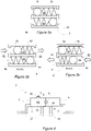
Figure 3a shows a possible embodiment of a pressure actuated two-way valve used in the present invention. -
Figure 3b shows the pressure actuated two-way valve ofFigure 3a when pressure P1 is greater than the pressure P2. -
Figure 3c shows the pressure actuated two-way valve ofFigure 3a when pressure P1 is less than the pressure P2. -
Figure 4 shows an shows an expansion tank according to a further embodiment of the present invention. -
Figure 5 shows a coolant system for electric circuits in a vehicle according to an embodiment of the present invention. -
Figure 6 shows a coolant system for electric circuits in a vehicle according to a further embodiment of the present invention. -
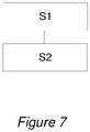
Figure 7 shows a flow chart of a method according to an embodiment of the present invention. - The present invention will now be described with reference to the accompanying drawings, in which preferred example embodiments of the invention are shown. The invention may, however, be embodied in other forms and should not be construed as limited to the herein disclosed embodiments. The disclosed embodiments are provided to fully convey the scope of the invention as defined by the appended claims to the skilled person.
-
Figure 1 shows two expansion tanks 2', 6' for cooling lines according to prior art systems for vehicles in need of more than one cooling line. Each cooling line (not shown) traditionally has its own expansion tank 2', 6' with a filling cap, especially if the cooling lines require different internal operating pressures. However it is, for reasons specified in the background section of this document, a number of drawback with two separate expansion tanks in vehicles. It is an object of this invention to provide an improved expansion tank for vehicles in need of more than one cooling line. - With reference to
Figure 2 , the first aspect of this invention will now be described. Anexpansion tank 1 for a vehicle withdual cooling lines first chamber 2 with a first fluid pressure P1 and theexpansion tank 1 comprises a firstfluid connector 3 in fluid connection with thefirst chamber 2 for connection to afirst cooling line 12. The expansion tank further comprises asecond chamber 6 with a second fluid pressure P2 and theexpansion tank 1 comprises a secondfluid connector 7 in fluid connection with thesecond chamber 2 for connection to a second cooling line 13.Thefirst chamber 2 and thesecond chamber 6 are in fluid connection with each other via a pressure actuated two-way valve 9 that acts as a one-way valve open in the direction towards thesecond chamber 6 at differential pressures between the second flud pressure P2 and the first fluid pressure P1 below a first predetermined differential pressure threshold DP1 and opens also in the direction towards thefirst chamber 2 at differential pressures above the first predetermined differential pressure threshold PD1. - The
expansion tank 1 comprises aninternal division wall 8 between thefirst chamber 2 and thesecond chamber 6, wherein theinternal division wall 8 has a first side surface 81 and a second side surface 82 opposite the first side surface, wherein the first side surface delimits the first chamber and the second side surface delimits the second chamber. - The
internal division wall 8 comprises anopening 83 forming a fluid connection between the first chamber and the second chamber and wherein the pressure actuated two-way valve 9 is arranged in the opening. - As the liquid in the
first cooling line 12 or thesecond cooling line 13 expands, it will be able to expand in thefirst chamber 2 and thesecond chamber 6, respectively via the firstfluid connector 3 and the secondfluid connector 7, respectively. Above the first predetermined differential pressure threshold DP1, i.e. when the pressure P2 in thesecond chamber 6 is relatively higher than the pressure P1 in the first chamber by a certain amount, the pressure actuatedvalve 9 will open so that liquid from the second chamber can enter thefirst chamber 2. The firstfluid connector 3 and the secondfluid connector 7 are inFigure 2 indicated to be valves that can be closed. However, the connectors do not need to be a closeable valve. It could also be a nozzle or any other suitable connector for attaching a cooling line. - The expansion tank can be used for two different fluid cooling lines with different pressures in the two cooling lines saving space in the vehicle. If the liquid in the high pressure second chamber expands it will be able to expand into the first chamber.
- The first predetermined differential pressure threshold DP1 is in the range of 0.2 bar to 3 bar above atmospheric pressure. The exact setting for the pressure actuated two-
way valve 9 is determined by the type of vehicle and the components that are to be temperature controlled by thefirst cooling line 12 and thesecond cooling line 13, respectively. The first predetermined differential pressure threshold DP1 is in preferred embodiment around 0.7 bar. - The
first chamber 2 further comprises a fillingcap 4 for filling theexpansion tank 1 with fluid 5. The fillingcap 4 further comprises an overpressure valve 41 opening towards the environment for releasing fluid at differential pressures between the first fluid pressure P1 in thefirst container 2 and the ambient air pressure AP above a second predetermined differential pressure threshold pressure DP2. If thefirst cooling line 12 and thefirst chamber 2 for some reason reaches a dangerous over pressure, the overpressure valve 41 will open and let fluid in the second chamber out. The second predetermined differential pressure threshold DP2 is in the range of 0 bar to 1.5 bar depending on the desired operating pressure of thefirst cooling line 12. -
Figure 3a shows a possible embodiment of the pressure actuated two-way valve used in the present invention. Theupper channel 94 contains aball 91 and aspring 93. Thelower channel 95 contains aball 92 and aspring 94. InFigure 3a the valve is closed in both directions as it is when the pressure is low on both sides of the valve. -
Figure 3b shows the same example pressure actuated two-way valve as inFigure 3a when pressure P1 is greater than the pressure P2 and the valve is open in the direction of thesecond chamber 6. The pressure P1 in thefirst chamber 2 has overcome the spring force of thespring 93 so that theball 91 has moved and opened thevalve section 94. The arrows indicate the flow direction through the pressure actuated two-way valve 9. -
Figure 3c shows the pressure actuated two-way valve ofFigure 3a when pressure P1 is less than the pressure P2, but above the first predetermined differential pressure threshold DP1, so that the pressure actuated two-way valve 9 is open towards thefirst chamber 2 of theexpansion tank 1. The pressure P2 in thesecond chamber 6 has overcome the spring force of thespring 94 so that theball 92 has moved and opened thevalve section 95. The arrows indicate the flow direction through the pressure actuated two-way valve 9. - Referring to
Figure 4 , an embodiment is shown where theexpansion tank 1 further comprises a thirdfluid connector 31 in fluid connection with thefirst chamber 2 for connection to thefirst cooling line 12. The firstfluid connector 3 and the thirdfluid connector 31 act as inlet and outlet, respectively, for cooling fluid, or the other way around. Theexpansion tank 1 further comprises afourth fluid connector 71 in fluid connection with thesecond chamber 2 for connection to thesecond cooling line 12. The secondfluid connector 7 and thefourth fluid connector 71 act as inlet and outlet, respectively, for cooling fluid, or the other way around. The chambers of the respective cooling lines are then in included in the fluid flow pass which help getting rid of any gas trapped that may be trapped in the cooling lines. - The second aspect of this invention is shown in
Figure 5 and discloses acoolant system 11 for electric circuits in a vehicle with an electric drive line comprising anexpansion tank 1 according to the first aspect. Further to the components of the expansion tank of the first aspect, the system comprises afirst cooling line 12 for cooling abattery 16 and asecond cooling line 13 for cooling a motor 17,18. Thefirst cooling line 12 is connected to thefirst fluid connector 31 of theexpansion tank 1 and thesecond cooling line 13 is connected in parallel to theexpansion tank 1 via theconnectors first cooling line 12 further comprises afirst circulation pump 14 for circulating the fluid in the first cooling line. The first cooling line also comprises aheat exchanger 19 for reducing the temperature in the first cooling line. Thesecond cooling line 13 further comprises asecond circulation pump 15 for circulating the fluid in thesecond cooling line 13. The second cooling line also comprises aheat exchanger 20 for reducing the temperature in the second cooling line. The fluid in thefirst cooling line 12 and the fluid in the second fluid line may thus expand in thefirst chamber 2 and thesecond chamber 6, respectively, of theexpansion tank 1. - A further embodiment of the second aspect of this invention is shown in
Figure 6 . Acoolant system 11 for electric circuits in a vehicle with an electric drive line is disclosed comprising anexpansion tank 1 according to the first aspect. Further to the components of the expansion tank of the first aspect, the system comprises afirst cooling line 12 for cooling abattery 16 and asecond cooling line 13 for cooling a motor 17,18. Thefirst cooling line 12 is connected to the firstfluid connector 3 of theexpansion tank 1 and thesecond cooling line 13 is connected to the secondfluid connector 7 of theexpansion tank 1. Thefirst cooling line 12 further comprises afirst circulation pump 14 for circulating the fluid in the first cooling line. The first cooling line also comprises aheat exchanger 19 for reducing the temperature in the first cooling line. Thesecond cooling line 13 further comprises asecond circulation pump 15 for circulating the fluid in thesecond cooling line 15. The second cooling line also comprises aheat exchanger 20 for reducing the temperature in the second cooling line. The fluid that is filled into theexpansion tank 1 is water with an optional anti-freezing component. - The vehicle having the system of the second aspect installed may have a motor 17 that is an Internal Combustion Engine but it may also have an electric motor 18. The vehicle may also be a hybrid vehicle with dual engines and a large battery, where both engines and the battery may need liquid cooling. In some embodiments one cooling line may be used for cooling two different components as e.g. an electric engine and high voltage battery.
- The third aspect of this invention shows a method for filling the expansion tank the first aspect or the
coolant system 11 according to the second aspect. With reference toFigure 7 the method comprises the steps of evacuating S1 theexpansion tank 1 creating a low pressure or vacuum forcing the pressure actuated two-way valve 9 to open and filling S2 the expansion tank with the liquid 5 during low pressure. When both fluid lines are empty, e.g. when the vehicle is new and is prepared for first use, the cooling lines need to be filled. To force the pressure actuated two-way valve 9 to open a low pressure can be applied to thefirst chamber 2 of theexpansion tank 1. The cooling liquid may then be filled into both lines via the filling cap of thefirst chamber 2. - The person skilled in the art realizes that the present invention is not limited to the preferred embodiments described above. The person skilled in the art further realizes that modifications and variations are possible within the scope of the appended claims. For example, if a vehicle would need three cooling lines, e.g. for dual drive lines and a battery, the expansion tank could have three chambers and two pressure actuated two-way valves. Vehicles with more than two drive lines may also need three or more cooling lines. A person skilled in the art realizes that the disclosed expansion tank can be realized with any number of chambers within the scope of the appended claims.
- Additionally, variations to the disclosed embodiments can be understood and effected by the skilled person in practicing the claimed invention, from a study of the drawings, the disclosure, and the appended claims.
Claims (15)
- An expansion tank (1) for a vehicle with dual cooling lines (12, 13), comprisinga first chamber (2) with a first fluid pressure (P1), wherein the expansion tank (1) comprises a first fluid connector (3) in fluid connection with the first chamber (2) for connection to a first cooling line (12),a second chamber (6) with a second fluid pressure (P2), wherein the expansion tank (1) comprises a second fluid connector (7) in fluid connection with the second chamber (2) for connection to a second cooling line (13),wherein the first chamber (2) and the second chamber (6) are in fluid connection via a pressure actuated two-way valve (9) that acts as a one-way valve open in the direction towards the second chamber (6) at differential pressures between the second fluid pressure (P2) and the first fluid pressure (P1) below a first predetermined differential pressure threshold (DP1) and opens also in the direction towards the first chamber (2) at differential pressures above the first predetermined differential pressure threshold (PD1).
- The expansion tank (1) according to claim 1, wherein the expansion tank (1) comprises an internal division wall (8) between the first chamber (2) and the second chamber (6), wherein the internal division wall (8) has a first side surface (81) and a second side surface (82) opposite the first side surface, wherein the first side surface delimits the first chamber and the second side surface delimits the second chamber.
- The expansion tank (1) according to claim 2, wherein the internal division wall (8) comprises an opening (83) forming a fluid connection between the first chamber and the second chamber and wherein the pressure actuated two-way valve (9) is arranged in the opening.
- The expansion tank (1) according to claim 1, wherein the first container (2) further comprises a filling cap (4) for filling the expansion tank (1) with fluid (5).
- The expansion tank (1) according to claim 2, wherein the filling cap (4) further comprises a over pressure valve (41) opening towards the environment for releasing fluid at differential pressures between the first fluid pressure (P1) in the first container (2) and the ambient air pressure (AP) above a second predetermined differential pressure threshold pressure (DP2).
- The expansion tank (1) according to any one of claim 1-3, wherein the first predetermined differential pressure threshold (DP1) is in the range of 0.2 bar to 3 bar. [Pressure above atmospheric pressure]
- The expansion tank (1) according to any one of claim 1-3, wherein the first predetermined differential pressure threshold (DP1) is around 0.7 bar.
- The expansion tank (1) according to any one of claims 3-5, wherein the second predetermined differential pressure threshold (DP2) is in the range of 0 bar to 1.5 bar.
- The expansion tank (1) according to any one of claims 3-6, wherein the second predetermined differential pressure threshold (DP2) is around 0.75 bar.
- The expansion tank (1) according to any one of the preceding claims, wherein the expansion tank (1) further comprises a third fluid connector (31) in fluid connection with the first chamber (2) for connection to the first cooling line (12), wherein the first fluid connector (3) and the third fluid connector (31) act as inlet and outlet, respectively, for cooling fluid, or the other way around.
- The expansion tank (1) according to any one of the preceding claims, wherein expansion tank (1) further comprises a fourth fluid connector (71) in fluid connection with the second chamber (2) for connection to the second cooling line (12), wherein the second fluid connector (7) and the fourth fluid connector (71) act as inlet and outlet, respectively, for cooling fluid, or the other way around.
- A coolant system (11) for electric circuits in a vehicle with an electric drive line comprising an expansion tank (1) according to any one of the preceding claims, further comprising:a first cooling line (12) for cooling a battery (16) and a second cooling line (13) for cooling a motor (17, 18),wherein the first cooling line (12) is connected to the first fluid connector (3) of the expansion tank (1) and the second cooling line (13) is connected to the second fluid connector (7) of the expansion tank (1).
- The coolant system (11) according to claim 12, wherein the fluid that is filled into the expansion tank (1) is water with an optional anti-freezing component.
- The coolant system (11) according to claim 12 or 13, wherein the motor (17, 18) is an Internal Combustion Engine (17) or an electric motor (18).
- A method for filling the expansion tank (1) according to any one of claims 1-11 or the coolant system (11) according to any one of claims 12-14, the method comprising the steps ofevacuating (S1) the expansion tank (1) creating a low pressure or vacuum forcing the pressure actuated two-way valve (9) to open,filling (S2) the expansion tank with the liquid (5) during low pressure.
Priority Applications (4)
| Application Number | Priority Date | Filing Date | Title |
|---|---|---|---|
| EP20179478.1A EP3922498B1 (en) | 2020-06-11 | 2020-06-11 | An expansion tank for a vehicle with dual cooling lines, a coolant system and a method for filling the expansion tank |
| PCT/CN2021/093707 WO2021249107A1 (en) | 2020-06-11 | 2021-05-13 | An expansion tank for a vehicle with dual cooling lines, a coolant system and a method for filling the expansion tank |
| CN202180041126.1A CN115698478A (en) | 2020-06-11 | 2021-05-13 | Expansion tank for a vehicle having a double cooling circuit, cooling system and method for filling an expansion tank |
| US17/988,441 US20230070793A1 (en) | 2020-06-11 | 2022-11-16 | Expansion tank for a vehicle with dual cooling lines, a coolant system and a method for filling the expansion tank |
Applications Claiming Priority (1)
| Application Number | Priority Date | Filing Date | Title |
|---|---|---|---|
| EP20179478.1A EP3922498B1 (en) | 2020-06-11 | 2020-06-11 | An expansion tank for a vehicle with dual cooling lines, a coolant system and a method for filling the expansion tank |
Publications (2)
| Publication Number | Publication Date |
|---|---|
| EP3922498A1 EP3922498A1 (en) | 2021-12-15 |
| EP3922498B1 true EP3922498B1 (en) | 2022-08-31 |
Family
ID=71092398
Family Applications (1)
| Application Number | Title | Priority Date | Filing Date |
|---|---|---|---|
| EP20179478.1A Active EP3922498B1 (en) | 2020-06-11 | 2020-06-11 | An expansion tank for a vehicle with dual cooling lines, a coolant system and a method for filling the expansion tank |
Country Status (4)
| Country | Link |
|---|---|
| US (1) | US20230070793A1 (en) |
| EP (1) | EP3922498B1 (en) |
| CN (1) | CN115698478A (en) |
| WO (1) | WO2021249107A1 (en) |
Family Cites Families (8)
| Publication number | Priority date | Publication date | Assignee | Title |
|---|---|---|---|---|
| US20110284107A1 (en) * | 2010-05-24 | 2011-11-24 | Mann+Hummel Gmbh | Multi-chamber fluid reservoir |
| KR101181045B1 (en) * | 2010-09-30 | 2012-09-07 | 현대자동차주식회사 | Cooling water reservoir tank for hybrid electric vehicle |
| WO2012114477A1 (en) * | 2011-02-23 | 2012-08-30 | スズキ株式会社 | Cooling device for hybrid vehicles |
| SE540917C2 (en) * | 2015-09-15 | 2018-12-18 | Scania Cv Ab | A cooling arrangement for an electric power unit in a vehicle |
| SE539924C2 (en) * | 2016-05-23 | 2018-01-16 | Scania Cv Ab | Expansion tank and cooling system comprising such an expansion tank |
| CN206600198U (en) * | 2017-01-24 | 2017-10-31 | 中国第一汽车股份有限公司 | A kind of automobile double cavate expansion tank |
| EP3781798B1 (en) * | 2018-04-17 | 2023-03-01 | Scania CV AB | A cooling system comprising at least two cooling circuits connected to a common expansion tank |
| CN208734425U (en) * | 2018-08-31 | 2019-04-12 | 众泰新能源汽车有限公司 | Vehicle expansion tank |
-
2020
- 2020-06-11 EP EP20179478.1A patent/EP3922498B1/en active Active
-
2021
- 2021-05-13 CN CN202180041126.1A patent/CN115698478A/en active Pending
- 2021-05-13 WO PCT/CN2021/093707 patent/WO2021249107A1/en active Application Filing
-
2022
- 2022-11-16 US US17/988,441 patent/US20230070793A1/en active Pending
Also Published As
| Publication number | Publication date |
|---|---|
| CN115698478A (en) | 2023-02-03 |
| WO2021249107A1 (en) | 2021-12-16 |
| US20230070793A1 (en) | 2023-03-09 |
| EP3922498A1 (en) | 2021-12-15 |
Similar Documents
| Publication | Publication Date | Title |
|---|---|---|
| CN101574923B (en) | Battery thermal system for vehicle | |
| US9771853B2 (en) | Waste heat accumulator/distributor system | |
| CN109899145B (en) | Flow control valve | |
| CN201129245Y (en) | Fuel antifreeze double-layer tank | |
| US20110120396A1 (en) | Integrated coolant flow control and heat exchanger device | |
| US20070044938A1 (en) | Dual surge tank for vehicle cooling system | |
| US20120168138A1 (en) | Integrated pump, coolant flow control and heat exchange device | |
| CN108666699B (en) | Temperature control device for a vehicle battery, vehicle having such a temperature control device, and method for controlling the temperature of a vehicle battery | |
| WO2000070209A1 (en) | Hermetically-sealed engine cooling system and related method of cooling | |
| CN115698477A (en) | Multi-circuit thermal management system comprising hybrid pipeline and vehicle | |
| US11415084B2 (en) | Storage tank for cryogenic liquid gas | |
| JP4941344B2 (en) | Hydraulic system | |
| US11454159B2 (en) | Methods and system for a coolant circuit valve | |
| EP3922498B1 (en) | An expansion tank for a vehicle with dual cooling lines, a coolant system and a method for filling the expansion tank | |
| SE418769B (en) | DEVICE FOR DRAINING REFRIGERANT FROM REFRIGERATOR AND HEATER | |
| CN211320221U (en) | Thermal management system and fuel cell vehicle with same | |
| EP3055526A1 (en) | Venting circuit | |
| US10934926B2 (en) | Cooling system of an internal combustion engine of a motor vehicle | |
| RU108489U1 (en) | SYSTEM OF LIQUID COOLING OF THE INTERNAL COMBUSTION ENGINE AND HEATING OF THE VEHICLE OF THE VEHICLE (OPTIONS) | |
| EP2578838B1 (en) | Cooling system for an engine | |
| CN112983623B (en) | Cooling system of explosion-proof diesel engine and control method thereof | |
| CN110014945A (en) | The charging unit and vehicle of vehicle | |
| US11584216B2 (en) | Cooling circuit arrangement | |
| EP2426393A1 (en) | Pressure-reducing gas storage devic, gas injection system and automobile | |
| CN210220331U (en) | Marine refrigeration cabin with semiconductor refrigeration device |
Legal Events
| Date | Code | Title | Description |
|---|---|---|---|
| PUAI | Public reference made under article 153(3) epc to a published international application that has entered the european phase |
Free format text: ORIGINAL CODE: 0009012 |
|
| STAA | Information on the status of an ep patent application or granted ep patent |
Free format text: STATUS: REQUEST FOR EXAMINATION WAS MADE |
|
| 17P | Request for examination filed |
Effective date: 20200611 |
|
| AK | Designated contracting states |
Kind code of ref document: A1 Designated state(s): AL AT BE BG CH CY CZ DE DK EE ES FI FR GB GR HR HU IE IS IT LI LT LU LV MC MK MT NL NO PL PT RO RS SE SI SK SM TR |
|
| B565 | Issuance of search results under rule 164(2) epc |
Effective date: 20201002 |
|
| GRAP | Despatch of communication of intention to grant a patent |
Free format text: ORIGINAL CODE: EPIDOSNIGR1 |
|
| STAA | Information on the status of an ep patent application or granted ep patent |
Free format text: STATUS: GRANT OF PATENT IS INTENDED |
|
| INTG | Intention to grant announced |
Effective date: 20220413 |
|
| GRAS | Grant fee paid |
Free format text: ORIGINAL CODE: EPIDOSNIGR3 |
|
| GRAA | (expected) grant |
Free format text: ORIGINAL CODE: 0009210 |
|
| STAA | Information on the status of an ep patent application or granted ep patent |
Free format text: STATUS: THE PATENT HAS BEEN GRANTED |
|
| AK | Designated contracting states |
Kind code of ref document: B1 Designated state(s): AL AT BE BG CH CY CZ DE DK EE ES FI FR GB GR HR HU IE IS IT LI LT LU LV MC MK MT NL NO PL PT RO RS SE SI SK SM TR |
|
| REG | Reference to a national code |
Ref country code: CH Ref legal event code: EP Ref country code: GB Ref legal event code: FG4D |
|
| REG | Reference to a national code |
Ref country code: AT Ref legal event code: REF Ref document number: 1515049 Country of ref document: AT Kind code of ref document: T Effective date: 20220915 |
|
| REG | Reference to a national code |
Ref country code: DE Ref legal event code: R096 Ref document number: 602020004794 Country of ref document: DE |
|
| REG | Reference to a national code |
Ref country code: IE Ref legal event code: FG4D |
|
| REG | Reference to a national code |
Ref country code: LT Ref legal event code: MG9D |
|
| REG | Reference to a national code |
Ref country code: NL Ref legal event code: MP Effective date: 20220831 |
|
| PG25 | Lapsed in a contracting state [announced via postgrant information from national office to epo] |
Ref country code: SE Free format text: LAPSE BECAUSE OF FAILURE TO SUBMIT A TRANSLATION OF THE DESCRIPTION OR TO PAY THE FEE WITHIN THE PRESCRIBED TIME-LIMIT Effective date: 20220831 Ref country code: RS Free format text: LAPSE BECAUSE OF FAILURE TO SUBMIT A TRANSLATION OF THE DESCRIPTION OR TO PAY THE FEE WITHIN THE PRESCRIBED TIME-LIMIT Effective date: 20220831 Ref country code: NO Free format text: LAPSE BECAUSE OF FAILURE TO SUBMIT A TRANSLATION OF THE DESCRIPTION OR TO PAY THE FEE WITHIN THE PRESCRIBED TIME-LIMIT Effective date: 20221130 Ref country code: LV Free format text: LAPSE BECAUSE OF FAILURE TO SUBMIT A TRANSLATION OF THE DESCRIPTION OR TO PAY THE FEE WITHIN THE PRESCRIBED TIME-LIMIT Effective date: 20220831 Ref country code: LT Free format text: LAPSE BECAUSE OF FAILURE TO SUBMIT A TRANSLATION OF THE DESCRIPTION OR TO PAY THE FEE WITHIN THE PRESCRIBED TIME-LIMIT Effective date: 20220831 Ref country code: FI Free format text: LAPSE BECAUSE OF FAILURE TO SUBMIT A TRANSLATION OF THE DESCRIPTION OR TO PAY THE FEE WITHIN THE PRESCRIBED TIME-LIMIT Effective date: 20220831 |
|
| REG | Reference to a national code |
Ref country code: AT Ref legal event code: MK05 Ref document number: 1515049 Country of ref document: AT Kind code of ref document: T Effective date: 20220831 |
|
| PG25 | Lapsed in a contracting state [announced via postgrant information from national office to epo] |
Ref country code: PL Free format text: LAPSE BECAUSE OF FAILURE TO SUBMIT A TRANSLATION OF THE DESCRIPTION OR TO PAY THE FEE WITHIN THE PRESCRIBED TIME-LIMIT Effective date: 20220831 Ref country code: IS Free format text: LAPSE BECAUSE OF FAILURE TO SUBMIT A TRANSLATION OF THE DESCRIPTION OR TO PAY THE FEE WITHIN THE PRESCRIBED TIME-LIMIT Effective date: 20221231 Ref country code: HR Free format text: LAPSE BECAUSE OF FAILURE TO SUBMIT A TRANSLATION OF THE DESCRIPTION OR TO PAY THE FEE WITHIN THE PRESCRIBED TIME-LIMIT Effective date: 20220831 |
|
| PG25 | Lapsed in a contracting state [announced via postgrant information from national office to epo] |
Ref country code: SM Free format text: LAPSE BECAUSE OF FAILURE TO SUBMIT A TRANSLATION OF THE DESCRIPTION OR TO PAY THE FEE WITHIN THE PRESCRIBED TIME-LIMIT Effective date: 20220831 Ref country code: RO Free format text: LAPSE BECAUSE OF FAILURE TO SUBMIT A TRANSLATION OF THE DESCRIPTION OR TO PAY THE FEE WITHIN THE PRESCRIBED TIME-LIMIT Effective date: 20220831 Ref country code: PT Free format text: LAPSE BECAUSE OF FAILURE TO SUBMIT A TRANSLATION OF THE DESCRIPTION OR TO PAY THE FEE WITHIN THE PRESCRIBED TIME-LIMIT Effective date: 20230102 Ref country code: ES Free format text: LAPSE BECAUSE OF FAILURE TO SUBMIT A TRANSLATION OF THE DESCRIPTION OR TO PAY THE FEE WITHIN THE PRESCRIBED TIME-LIMIT Effective date: 20220831 Ref country code: DK Free format text: LAPSE BECAUSE OF FAILURE TO SUBMIT A TRANSLATION OF THE DESCRIPTION OR TO PAY THE FEE WITHIN THE PRESCRIBED TIME-LIMIT Effective date: 20220831 Ref country code: CZ Free format text: LAPSE BECAUSE OF FAILURE TO SUBMIT A TRANSLATION OF THE DESCRIPTION OR TO PAY THE FEE WITHIN THE PRESCRIBED TIME-LIMIT Effective date: 20220831 Ref country code: AT Free format text: LAPSE BECAUSE OF FAILURE TO SUBMIT A TRANSLATION OF THE DESCRIPTION OR TO PAY THE FEE WITHIN THE PRESCRIBED TIME-LIMIT Effective date: 20220831 |
|
| PG25 | Lapsed in a contracting state [announced via postgrant information from national office to epo] |
Ref country code: SK Free format text: LAPSE BECAUSE OF FAILURE TO SUBMIT A TRANSLATION OF THE DESCRIPTION OR TO PAY THE FEE WITHIN THE PRESCRIBED TIME-LIMIT Effective date: 20220831 Ref country code: EE Free format text: LAPSE BECAUSE OF FAILURE TO SUBMIT A TRANSLATION OF THE DESCRIPTION OR TO PAY THE FEE WITHIN THE PRESCRIBED TIME-LIMIT Effective date: 20220831 |
|
| REG | Reference to a national code |
Ref country code: DE Ref legal event code: R097 Ref document number: 602020004794 Country of ref document: DE |
|
| PG25 | Lapsed in a contracting state [announced via postgrant information from national office to epo] |
Ref country code: NL Free format text: LAPSE BECAUSE OF FAILURE TO SUBMIT A TRANSLATION OF THE DESCRIPTION OR TO PAY THE FEE WITHIN THE PRESCRIBED TIME-LIMIT Effective date: 20220831 Ref country code: AL Free format text: LAPSE BECAUSE OF FAILURE TO SUBMIT A TRANSLATION OF THE DESCRIPTION OR TO PAY THE FEE WITHIN THE PRESCRIBED TIME-LIMIT Effective date: 20220831 |
|
| PLBE | No opposition filed within time limit |
Free format text: ORIGINAL CODE: 0009261 |
|
| STAA | Information on the status of an ep patent application or granted ep patent |
Free format text: STATUS: NO OPPOSITION FILED WITHIN TIME LIMIT |
|
| PGFP | Annual fee paid to national office [announced via postgrant information from national office to epo] |
Ref country code: FR Payment date: 20230630 Year of fee payment: 4 Ref country code: DE Payment date: 20230613 Year of fee payment: 4 |
|
| 26N | No opposition filed |
Effective date: 20230601 |
|
| PG25 | Lapsed in a contracting state [announced via postgrant information from national office to epo] |
Ref country code: MC Free format text: LAPSE BECAUSE OF FAILURE TO SUBMIT A TRANSLATION OF THE DESCRIPTION OR TO PAY THE FEE WITHIN THE PRESCRIBED TIME-LIMIT Effective date: 20220831 |
|
| PG25 | Lapsed in a contracting state [announced via postgrant information from national office to epo] |
Ref country code: MC Free format text: LAPSE BECAUSE OF FAILURE TO SUBMIT A TRANSLATION OF THE DESCRIPTION OR TO PAY THE FEE WITHIN THE PRESCRIBED TIME-LIMIT Effective date: 20220831 |
|
| REG | Reference to a national code |
Ref country code: CH Ref legal event code: PL |
|
| REG | Reference to a national code |
Ref country code: BE Ref legal event code: MM Effective date: 20230630 |
|
| PG25 | Lapsed in a contracting state [announced via postgrant information from national office to epo] |
Ref country code: LU Free format text: LAPSE BECAUSE OF NON-PAYMENT OF DUE FEES Effective date: 20230611 |
|
| REG | Reference to a national code |
Ref country code: IE Ref legal event code: MM4A |
|
| PG25 | Lapsed in a contracting state [announced via postgrant information from national office to epo] |
Ref country code: LU Free format text: LAPSE BECAUSE OF NON-PAYMENT OF DUE FEES Effective date: 20230611 |
|
| PG25 | Lapsed in a contracting state [announced via postgrant information from national office to epo] |
Ref country code: IE Free format text: LAPSE BECAUSE OF NON-PAYMENT OF DUE FEES Effective date: 20230611 |