EP3922149B1 - Gerät zur essenszubereitung - Google Patents
Gerät zur essenszubereitung Download PDFInfo
- Publication number
- EP3922149B1 EP3922149B1 EP21177848.5A EP21177848A EP3922149B1 EP 3922149 B1 EP3922149 B1 EP 3922149B1 EP 21177848 A EP21177848 A EP 21177848A EP 3922149 B1 EP3922149 B1 EP 3922149B1
- Authority
- EP
- European Patent Office
- Prior art keywords
- cover
- container
- locking member
- fixed position
- food preparation
- Prior art date
- Legal status (The legal status is an assumption and is not a legal conclusion. Google has not performed a legal analysis and makes no representation as to the accuracy of the status listed.)
- Active
Links
- 235000013305 food Nutrition 0.000 title claims description 74
- 238000002360 preparation method Methods 0.000 title claims description 62
- 230000033001 locomotion Effects 0.000 claims description 38
- 238000006073 displacement reaction Methods 0.000 claims description 17
- 238000010438 heat treatment Methods 0.000 claims description 11
- 230000005540 biological transmission Effects 0.000 claims description 10
- 238000010411 cooking Methods 0.000 claims description 7
- 238000013519 translation Methods 0.000 claims description 5
- 230000000903 blocking effect Effects 0.000 description 85
- 239000004615 ingredient Substances 0.000 description 4
- 238000012986 modification Methods 0.000 description 3
- 230000004048 modification Effects 0.000 description 3
- 208000027418 Wounds and injury Diseases 0.000 description 2
- 240000008042 Zea mays Species 0.000 description 2
- 238000009835 boiling Methods 0.000 description 2
- 230000006378 damage Effects 0.000 description 2
- 208000014674 injury Diseases 0.000 description 2
- 241001415961 Gaviidae Species 0.000 description 1
- 244000261422 Lysimachia clethroides Species 0.000 description 1
- 238000013019 agitation Methods 0.000 description 1
- 238000012790 confirmation Methods 0.000 description 1
- 230000003111 delayed effect Effects 0.000 description 1
- 238000013461 design Methods 0.000 description 1
- 238000001514 detection method Methods 0.000 description 1
- 230000000694 effects Effects 0.000 description 1
- 238000005485 electric heating Methods 0.000 description 1
- 235000011194 food seasoning agent Nutrition 0.000 description 1
- 235000021268 hot food Nutrition 0.000 description 1
- 230000006698 induction Effects 0.000 description 1
- 238000000034 method Methods 0.000 description 1
- 230000009897 systematic effect Effects 0.000 description 1
Images


Classifications
-
- A—HUMAN NECESSITIES
- A47—FURNITURE; DOMESTIC ARTICLES OR APPLIANCES; COFFEE MILLS; SPICE MILLS; SUCTION CLEANERS IN GENERAL
- A47J—KITCHEN EQUIPMENT; COFFEE MILLS; SPICE MILLS; APPARATUS FOR MAKING BEVERAGES
- A47J36/00—Parts, details or accessories of cooking-vessels
- A47J36/06—Lids or covers for cooking-vessels
- A47J36/10—Lid-locking devices
-
- A—HUMAN NECESSITIES
- A47—FURNITURE; DOMESTIC ARTICLES OR APPLIANCES; COFFEE MILLS; SPICE MILLS; SUCTION CLEANERS IN GENERAL
- A47J—KITCHEN EQUIPMENT; COFFEE MILLS; SPICE MILLS; APPARATUS FOR MAKING BEVERAGES
- A47J27/00—Cooking-vessels
- A47J27/002—Construction of cooking-vessels; Methods or processes of manufacturing specially adapted for cooking-vessels
-
- A—HUMAN NECESSITIES
- A47—FURNITURE; DOMESTIC ARTICLES OR APPLIANCES; COFFEE MILLS; SPICE MILLS; SUCTION CLEANERS IN GENERAL
- A47J—KITCHEN EQUIPMENT; COFFEE MILLS; SPICE MILLS; APPARATUS FOR MAKING BEVERAGES
- A47J36/00—Parts, details or accessories of cooking-vessels
-
- A—HUMAN NECESSITIES
- A47—FURNITURE; DOMESTIC ARTICLES OR APPLIANCES; COFFEE MILLS; SPICE MILLS; SUCTION CLEANERS IN GENERAL
- A47J—KITCHEN EQUIPMENT; COFFEE MILLS; SPICE MILLS; APPARATUS FOR MAKING BEVERAGES
- A47J43/00—Implements for preparing or holding food, not provided for in other groups of this subclass
- A47J43/04—Machines for domestic use not covered elsewhere, e.g. for grinding, mixing, stirring, kneading, emulsifying, whipping or beating foodstuffs, e.g. power-driven
- A47J43/046—Machines for domestic use not covered elsewhere, e.g. for grinding, mixing, stirring, kneading, emulsifying, whipping or beating foodstuffs, e.g. power-driven with tools driven from the bottom side
Definitions
- the present invention generally relates to food preparation appliances, and in particular food preparation appliances arranged to automatically heat and work food to be prepared previously placed in a working tank by a user.
- the invention relates to a food processor comprising a tank in which the user places ingredients, to then close it with a lid, and the food processor then automatically prepares a dish ready to be consumed, by heating and working the ingredients of the working tank.
- the food preparation appliance disclosed in this document is complex because it comprises a lid which can be blocked on the working tank by longitudinal shafts anchored in a vertical return of the food preparation appliance. Consequently, it is necessary to provide a complex and robust frame (which therefore forms a gooseneck), which is expensive and bulky. Consequently, access to the working tank is limited by these lateral blocking members, and the ergonomics of use are thereby limited. Finally, the control of the blocking members requires the operation of a geared motor, which is long and can cause the user to wait.
- WO201912208 A1 discloses a food preparation appliance comprising a motorized device used to block a lid on a cooking tank, after locking the lid on the tank by rotation.
- a drawback of the embodiment described in this document lies in the absence of a solution to also secure the cooking vessel on the housing, which can affect the safety of use. It is necessary for example to provide a manual locking of the tank which increases the costs and the complexity of use.
- EP2698088A1 represents the closest state of the art and discloses the preamble of claim 1.
- An object of the present invention is to respond to the drawbacks of the prior art mentioned above and in particular, first of all, to propose a food preparation appliance (a food processor) with a simple structure and easy to use while guaranteeing the safety of the user, even if hot food is in the tank.
- a food preparation appliance a food processor
- the locking securing means comprise a first blocking member arranged to block the cover in the closed position, and a second blocking member arranged to block the tank mounted on the device.
- a first blocking member arranged to block the cover in the closed position
- a second blocking member arranged to block the tank mounted on the device.
- the means for securing the locking comprise a transmission line or chain which connects the geared motor to the first and to the second blocking member in order to impose a movement on them.
- the locking securing means comprise at least one connecting device arranged between the geared motor and the second locking member.
- a connecting device makes it possible to provide a first direction of displacement different from the second direction of movement without requiring a second gearmotor. The bulk therefore remains limited, and the freedom of design is increased.
- the connecting device comprises a bevel gear device.
- the connecting device comprises a cam device.
- the connecting device comprises a rack and pinion device.
- the connecting device comprises a connecting rod.
- the geared motor has three stop positions. In the rest configuration of the geared motor, neither of the first or of the second blocking member is engaged with the tank or the cover, so that all assembly/disassembly operations are possible. In the end-of-travel configuration of the geared motor, the first and the second blocking member are engaged respectively with the cover and the tank, so that all assembly/disassembly operations are impossible.
- the geared motor In addition, provision is made for the geared motor to be stopped in an intermediate configuration, in which only the second blocking member is engaged with the tank, and the first blocking member is not engaged with the lid. The tank is therefore impossible to disassemble, but the cover can be removed if necessary.
- the device in this configuration if no risk of overflow or injury to the user is identified even with the cover removed, depending on the conditions of use.
- the locking securing means are partly housed in the handle, which makes it possible to hide them from the user.
- the means for securing the locking comprise a rod carrying the first blocking member and arranged to be moved by the geared motor according to a translational movement between the securing position of the lid and the non-securing position of the lid, preferably according to a sliding connection.
- the locking securing means comprise a rack engaged with the geared motor to move the rod.
- the connecting device is coupled to the rack.
- This implementation makes it possible to propose a compact device with the connection device as close as possible to the geared motor.
- the tank carries a side cover extending from a lower part to an upper part of the tank and the rod is housed mainly between the tank and the side cover.
- the first direction of displacement is different from the second direction of displacement, and preferably the first direction of displacement is included in a first plane positioned at 90° ⁇ 15° with respect to a second plane comprising the second direction of displacement.
- the food preparation appliance comprises lid locking means, arranged to lock the lid in the closed position, and arranged to be controlled manually.
- the lid locking means comprise a bayonet-type interface.
- the food preparation appliance comprises means for locking the tank, arranged to lock the tank mounted on the housing to the housing, and arranged to be controlled manually.
- the tank is arranged to be mounted in translation on the housing in a tank mounting direction, preferably in an axial direction of the tank, and the second direction of movement of the second blocking member is perpendicular to the mounting direction of tank. Blocking is effective.
- the cover is arranged to be mounted in rotation on the tank according to an axis of rotation for mounting the cover, preferably parallel to an axial direction of the tank, and the first direction of displacement of the first blocking member is parallel to the axis of rotation of the assembly of the cover.
- the gear motor is arranged in the housing, the gear motor comprises a control arm and the control arm comprises at least one limit stop provided to come into abutment with the housing in order to define the non-secured position of the cover of the first blocking member and/or the securing position of the cover of the first blocking member.
- the geared motor is arranged to move the first blocking member from the cover securing position to the cover non-securing position.
- the food preparation appliance comprises a heating device arranged to provide cooking heat to the food received in the tank.
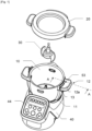
- FIG. 1 represents a first embodiment of a food preparation appliance with a housing 40, removably receiving a tank 10 which can contain a mobile working member 30 and be closed by a lid 20.
- the tank 10 can here be mounted according to an axial movement on the housing 40.
- the mobile working member 30, here a cutting tool is placed in the tank 10, and is then coupled with a motor located in the housing 40, to be driven in rotation, once the tank 10 is closed with the lid 20.
- the tank 10 has two lateral extensions 11 which go up along the tank 10, and which end in two handles 12 at the level of the upper part of the tank 10, and each comprising a slot 13 provided on an upper surface 12a.
- the cover 20 is provided to be mounted on the tank 10 following a rotational movement (a pivot connection is provided), in order to engage a male part of the cover 20 in the slots 13, passing from an unlocked position (cover 20 placed on the tank 10) to a closed position, locked, in which the cover 20 is in the final position on the food preparation appliance.
- This locking system is for example a bayonet locking.
- the lid 20 in the unlocked position closes the tank 10, and can be removed freely, but can no longer be lifted from the tank 10 once it has been moved/pivoted towards the closed position, locked, which provides safety of use when the mobile working member 30 is rotating in the tank 10.
- the bayonet locking means mentioned above can be elastic, that is to say that the user makes pass a "notch" to the cover 20 by mounting the cover 20 so that a flexible tab of the bayonet locking means forms an obstacle to a return back during use.
- the user by turning the lid 20 in the opposite direction, unlocks the bayonet locking means, by forcing to pass the "notch" again, and can remove the lid 20 by finishing the pivoting.
- the food preparation appliance can also comprise a heating device for heating and/or cooking the food to be prepared, in particular an induction heating device arranged in the casing 40, or else an electric heating resistance placed in the casing 40, on the housing 40, under the tank 10, around the tank 10, or in the tank 10.
- a heating device for heating and/or cooking the food to be prepared in particular an induction heating device arranged in the casing 40, or else an electric heating resistance placed in the casing 40, on the housing 40, under the tank 10, around the tank 10, or in the tank 10.
- the device of the figure 1 comprises a control panel 44 in the front part of the housing 40 to allow a user to select a culinary gesture (typically a preparation operation or a cooking temperature) or a complete cooking recipe (a series of culinary gestures spread over time ).
- a culinary gesture typically a preparation operation or a cooking temperature
- a complete cooking recipe a series of culinary gestures spread over time .
- the food preparation appliance may include detection means (presence sensors) which indicate that the tank 10 is in place, and that the lid 20 is in position, before starting the preparation, by heating and/or working the food to be prepared.
- detection means presence sensors
- a speed of rotation of the mobile working member 30 can be imposed in a speed range ranging from 0 to 300 revolutions / min (300min-1), in stages, from variable or constant way.
- the motor located in the housing 40 is advantageously associated with a reduction gear.
- the heating device can be chosen to impose on the food to be prepared a temperature ranging up to 130° C. for example.
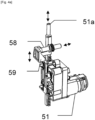
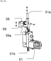
- THE figure 4a And 4b show in detail the arrangement of the means for securing the locking at the level of the geared motor 51.
- the rack 51b, engaged with the geared motor 51 is integral with the control arm 51a which can therefore move in translation.
- the cam 59 is embedded on the control arm 51a, so that it follows the movement of the latter. Consequently, the second locking member 58, in contact with the cam track 59a of the cam 59 can move in a direction perpendicular to the direction of movement of the control arm 51a (in a vertical plane).
- a spring is provided to constantly push the second blocking member 58 against the cam track 59a and bring it back to the non-securing position of the tank 10.
- a spring is also provided to constantly push the rod 52 against the control arm 51a and consequently return the first locking member 53 to the non-securing position of the cover 20.
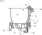
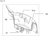
- FIG. 5 shows a partial section of the housing 40, without the tank 10, so as to represent the orifices in the housing 40 from which emerge the second blocking member 58, and the control arm 51a.
- the geared motor 51 is therefore arranged to move the first blocking member 53 and the second blocking member 58. For this purpose, it can be controlled between a rest configuration ( figure 2 ), and a limit switch configuration ( picture 3 ).
- the first blocking member 53 is movable in a first direction of movement (a vertical direction, that of the rod 52), between a non-securing position of the cover 20, in which a movement of opening of the lid 20 from the closed position is authorized, and a securing position of the lid 20, in which the first blocking member 53 hinders the opening movement of the lid 20 from the closed position.
- the cover 20 comprises a counter form of engagement 22 to receive the end (an engagement portion) of the first locking member 53 when it is in the securing position of the cover 20, so as to block an unlocking movement of the cover 20.
- the second locking member 58 is movable, under the effect of the cam 59) according to a second direction of displacement (a horizontal direction on the figure 2 ), between a non-securing position of the tank 10, in which disassembly of the tank 10 mounted on the housing 40 is authorized, and a securing position of the tank 10, in which the second blocking member 58 hinders the disassembly of the tank 10 mounted on the housing 40.
- the second blocking member 58 is mounted on the housing 40 according to a sliding connection or a sliding pivot connection.
- the tank 10 comprises a hole 18 to accommodate the end (an engagement portion) of the second blocking member 58 when it is in the position for securing the tank 10, so as to block a dismantling/unlocking movement of the tank 10.
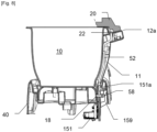
- FIG. 2 therefore shows the food preparation appliance with the first blocking member 53 in the non-securing position of the cover 20, and the second blocking member 58 in the non-securing position of the tank 10. Consequently, the tank 10 and the cover 20 can be assembled or disassembled freely by the user, since no movement is impeded by the first blocking member 53 or the second blocking member 58, the geared motor 51 having been controlled to be in a rest configuration.
- the tank 10 and the cover 20 can no longer be disassembled / unlocked freely by the user, because these disassembly / unlocking movements are hindered by the first locking member 53 and the second locking member 58, the geared motor 51 being then in the end-of-travel configuration.
- the food preparation appliance drives the gearmotor 51 to simultaneously lock the tank 10 and secure the locking of the lid 20, as described above.
- the movement of the first blocking member 53 is perpendicular to the movement of the counter engagement form 22 during the unlocking of the cover 20, and the movement of the second blocking member 58 is also perpendicular to the movement of the hole 18 during disassembly. of the tank 10.
- the blocking of the tank 10 and of the lid 20 is therefore effective.
- the example shown shows a cam 59 to provide these two different directions of movement between the first blocking member 53 and the second blocking member 58.
- a connecting rod, a double rack, etc. can be considered.
- FIG. 6 represents a second implementation in which it is planned to be able to dissociate the locking of the tank 10 and the securing of the locking of the lid 20.
- it can be interesting to allow, under certain conditions, to be able to unlock and disassemble the lid 20, without however unlocking/removing tank 10, to add ingredients for example.
- it must be guaranteed that the cover 20 cannot be unlocked/dismantled, in the event of a risk of boiling/overflowing for example. It may therefore be advantageous to allow unlocking/removal of the cover 20 alone, under conditions.
- control arm 151a is shorter than control arm 51a of the first embodiment.
- the geared motor 151 in the rest configuration there is then a predetermined clearance JP between the control arm 151a and the rod 52.
- the first blocking member 53 is in the non-securing position of the cover 20, and the second blocking member 58 is in the non-securing position of the tank 10. Consequently, the tank 10 and cover 20 can be assembled or disassembled freely by the user, since no movement is impeded by the first blocking member 53 or the second blocking member 58.
- FIG 8 shows the food preparation appliance of the figure 7 , where the geared motor 151 has been controlled to go into the intermediate configuration.
- the control arm 151a has been moved upwards by a stroke less than or equal to the predetermined play JP, and the cam 159, on board the control arm 151a, has pushed the second locking member 58 into the position for securing the tank 10.
- the control arm 151a has not moved the rod 52, so that the first locking member 53 remains in the non-securing position of the cover 20. Consequently, the tank 10 can no longer be disassembled freely by the user, since such movement is hindered by the second blocking member 58.
- the cover 20 can always be mounted or dismounted freely by the user, since no movement is hampered by the first blocking member 53.
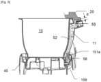
- FIG 9 shows the food preparation appliance of the figure 7 , where the gearmotor 151 has been controlled to go to the end of race.
- the control arm 151a has again been moved upwards this time by a total travel greater than the predetermined clearance JP.
- the cam 159 on board the control arm 151a, continues to push the second blocking member 58 into the position for securing the tank 10.
- the control arm 151a has moved the rod 52, so that the first locking member lock 53 is now in position for securing cover 20 (see distance d). Consequently, the tank 10 and the cover 20 can no longer be disassembled freely by the user, since such movements are hindered by the first blocking member 53 and the second blocking member 58.
- the figure 9 shows the means for securing the locking of the food preparation appliance in a secure configuration in which neither the lid 20 nor the tank 10 can be disassembled
- the figure 8 shows the means for securing the locking of the food preparation appliance in a partial securing configuration in which only the lid 20 can be removed
- the figure 7 shows the means for securing the locking of the food preparation appliance in a free dismantling configuration in which any dismantling is authorized. It is possible to switch the food preparation appliance from one configuration to the other under certain conditions, in particular depending on the recipe steps and the state of the food in the tank 10.
- the solution presented here is based on a predetermined play JP in the transmission between the geared motor 151 and the first blocking member 53.
- the first locking member 53 is set back significantly from the upper surface 12a; in partial securing configuration, the first blocking member 53 is flush with the upper surface 12a; in a secure configuration, the first control unit Lock 53 projects from top surface 12a and can engage cover 20.
- the locking of the lid 20 in the locked position is systematic, and the unlocking is carried out either immediately or simultaneously when the food preparation appliance is stopped if no risk of overflow is identified, be delayed, if a risk of overflow is identified (predetermined temperature exceeded and predetermined speed exceeded).
- the locking securing means are conditionally deactivated.
- the cover 20 can be blocked in the locked position only if the two conditions are programmed (that is to say when the food preparation appliance starts up, for example simultaneously when the movement of the mobile working member or even after, but before the speed exceeds the predetermined speed and the temperature exceeds the predetermined temperature), or as soon as these two conditions are measured by the food preparation appliance (during program). It is then possible to maintain the locking securing means activated in a secure configuration throughout the subsequent use of the food preparation appliance, and during a rest timer (at least five seconds, and preferably at least eight or ten seconds), after the moving part and/or the heating has completely stopped. Thus the opening of the cover 20 is impossible only when there is a risk of overflow.
- the means for securing the locking are not switched to the secure configuration of the figure 9 at start-up or during use only if it is planned or measured to exceed the predetermined speed and the predetermined temperature during the next cycle, and the blockage is maintained for a short time even after the appliance has completely stopped culinary preparation. Provision can be made on the control panel 44 to inform the user whether opening is possible or not. In other words, the locking securing means are conditionally activated.
- the food preparation appliance therefore comprises a control unit and means for measuring or acquiring the temperature, and means for measuring or acquiring the speed of the mobile working member 30.
- the predetermined temperature can be 50° C. or preferentially 60° C.
- the means for securing the locking must be changed to a secure configuration (if the predetermined temperature is exceeded), as soon as a speed range is chosen or measured (for example the last step of several preprogrammed speed steps), or as soon as the chosen or measured speed exceeds a particular value, for example 160 revolutions/min or more preferably 250 revolutions/min.
Landscapes
- Engineering & Computer Science (AREA)
- Food Science & Technology (AREA)
- Manufacturing & Machinery (AREA)
- Mechanical Engineering (AREA)
- Food-Manufacturing Devices (AREA)
- Cookers (AREA)
- Frying-Pans Or Fryers (AREA)
- Baking, Grill, Roasting (AREA)
- Seeds, Soups, And Other Foods (AREA)
- Jellies, Jams, And Syrups (AREA)
Claims (16)
- Gerät zur Essenszubereitung, umfassend:- ein Gehäuse (40),- einen Behälter (10), der abnehmbar am Gehäuse (40) angebracht und so eingerichtet ist, dass er zuzubereitende Lebensmittel aufnehmen kann,- mindestens ein bewegliches Arbeitsorgan (30), das im Behälter (10) angeordnet und so eingerichtet ist, dass es die im Behälter (10) aufgenommenen Lebensmittel bearbeiten kann,- einen Motor, der im Gehäuse (40) angeordnet und so eingerichtet ist, dass er das bewegliche Arbeitsorgan (30) in Bewegung setzen kann,- einen abnehmbaren Deckel (20), der abnehmbar in einer Verschlussstellung angebracht ist, sodass er dem Behälter (10) einen geschlossenen Zustand verleiht, in dem der Behälter (10) vom Deckel (20) geschlossen wird, wobei das Gerät zur Essenszubereitung Mittel zum Sichern der Verriegelung des Deckels (20) umfasst, wobei die Mittel zum Sichern der Verriegelung umfassen:dadurch gekennzeichnet:• ein erstes Sperrorgan (53), das in einer ersten Bewegungsrichtung zwischen einer Stellung zur Nichtsicherung des Deckels (20), in der eine Bewegung zum Öffnen des Deckels (20) aus der Verschlussstellung heraus möglich ist, und einer Stellung zur Sicherung des Deckels (20), in der das erste Sperrorgan (53) die Bewegung zum Öffnen des Deckels (20) aus der Verschlussstellung heraus behindert, beweglich ist,• einen Getriebemotor (51; 151), der so eingerichtet ist, dass er das erste Sperrorgan (53) in der ersten Bewegungsrichtung zwischen der Stellung zur Nichtsicherung des Deckels (20) und der Stellung zur Sicherung des Deckels (20) bewegen kann,- dass die Mittel zum Sichern der Verriegelung ein zweites Sperrorgan (58) umfassen, das in einer zweiten Bewegungsrichtung zwischen einer Stellung zur Nichtsicherung des Behälters (10), in der ein Ausbauen des am Gehäuse (40) angebrachten Behälters (10) möglich ist, und einer Stellung zur Sicherung des Behälters (10), in der das zweite Sperrorgan (58) das Ausbauen des am Gehäuse (40) angebrachten Behälters (10) behindert, beweglich ist,- und dass der Getriebemotor (51; 151) so eingerichtet ist, dass er das zweite Sperrorgan (58) in der zweiten Bewegungsrichtung zwischen der Stellung zur Nichtsicherung des Behälters (10) und der Stellung zur Sicherung des Behälters (10) bewegen kann.
- Gerät zur Essenszubereitung nach Anspruch 1, dadurch gekennzeichnet, dass die Mittel zum Sichern der Verriegelung mindestens eine Verbindungsvorrichtung umfassen, die zwischen dem Getriebemotor (51; 151) und dem zweiten Sperrorgan (58) eingerichtet ist.
- Gerät zur Essenszubereitung nach Anspruch 2, dadurch gekennzeichnet, dass die Verbindungsvorrichtung eine Winkeltriebvorrichtung umfasst.
- Gerät zur Essenszubereitung nach Anspruch 2 oder 3, dadurch gekennzeichnet, dass die Verbindungsvorrichtung eine Nockenvorrichtung (59) umfasst.
- Gerät zur Essenszubereitung nach einem der Ansprüche 1 bis 4, wobei der Getriebemotor (51; 151) so eingerichtet ist, dass er angesteuert werden kann zwischen:- einer Ruhekonfiguration, in der sich das erste Sperrorgan (53) in der Stellung zur Nichtsicherung des Deckels (20) befindet und sich das zweite Sperrorgan (58) in der Stellung zur Nichtsicherung des Behälters (10) befindet, und- einer Hubende-Konfiguration, in der sich das erste Sperrorgan (53) in der Stellung zur Sicherung des Deckels (20) befindet und sich das zweite Sperrorgan (58) in der Stellung zur Sicherung des Behälters (10) befindet, dadurch gekennzeichnet, dass der Getriebemotor (51; 151) so eingerichtet ist, dass er in einer Zwischenkonfiguration anhalten kann, in der:- sich das erste Sperrorgan (53) in der Stellung zur Nichtsicherung des Deckels (20) befindet und sich das zweite Sperrorgan (58) in der Stellung zur Sicherung des Behälters (10) befindet.
- Gerät zur Essenszubereitung nach Anspruch 5, das eine Übertragung zwischen dem Getriebemotor (51; 151) und einem Eingriffsabschnitt des ersten Sperrorgans (53) umfasst, der so eingerichtet ist, dass er in eine Gegeneingriffsform (22) des Deckels (20) eingreifen kann, dadurch gekennzeichnet:- dass ein vorbestimmtes Spiel (JP) im Bereich der Übertragung oder zwischen dem Eingriffsabschnitt des ersten Sperrorgans (53) und der Gegeneingriffsform (22) des Deckels (20) vorgesehen ist,- dass der vom Getriebemotor (51; 151) vorgegebene Hub des ersten Sperrorgans (53) zwischen der Ruhekonfiguration und der Zwischenkonfiguration kleiner oder gleich dem vorbestimmten Spiel (JP) ist.
- Gerät zur Essenszubereitung nach einem der Ansprüche 1 bis 6, wobei der Behälter (10) einen Griff (12) umfasst, dadurch gekennzeichnet, dass:- sich das erste Sperrorgan (53) aus dem Griff (12) heraus erstreckt, wenn das erste Sperrorgan (53) die Stellung zur Sicherung des Deckels (20) einnimmt, und/oder- sich das zweite Sperrorgan (58) aus dem Gehäuse (40) heraus erstreckt, wenn das zweite Sperrorgan (58) die Stellung zur Sicherung des Behälters (10) einnimmt.
- Gerät zur Essenszubereitung nach einem der Ansprüche 1 bis 7, dadurch gekennzeichnet, dass die Mittel zum Sichern der Verriegelung eine Stange (12) umfassen, die das erste Sperrorgan (53) trägt und so eingerichtet ist, dass sie vom Getriebemotor (51; 151) in einer Verschiebebewegung zwischen der Stellung zur Sicherung des Deckels (20) und der Stellung zur Nichtsicherung des Deckels (20), vorzugsweise gemäß einer Gleitverbindung, bewegt werden kann.
- Gerät zur Essenszubereitung nach Anspruch 8, dadurch gekennzeichnet, dass die Mittel zum Sichern der Verriegelung eine Zahnstange (51b; 151b) umfassen, die mit dem Getriebemotor (51; 151) ineinandergreift, um die Stange (12) zu bewegen.
- Gerät zur Essenszubereitung nach Anspruch 9 in Abhängigkeit von einem der Ansprüche 2 bis 6, dadurch gekennzeichnet, dass die Verbindungsvorrichtung an die Zahnstange (51b; 151b) gekoppelt ist.
- Gerät zur Essenszubereitung nach einem der Ansprüche 1 bis 10, dadurch gekennzeichnet, dass die Mittel zum Sichern der Verriegelung umfassen:- ein erstes elastisches Organ, wie etwa eine Feder, das so eingerichtet ist, dass es das erste Sperrorgan (53) aus der Stellung zur Sicherung des Deckels (20) in die Stellung zur Nichtsicherung des Deckels (20) drücken kann, und/oder- ein zweites elastisches Organ, wie etwa eine Feder, das so eingerichtet ist, dass es das zweite Sperrorgan (58) aus der Stellung zur Sicherung des Behälters (10) in die Stellung zur Nichtsicherung des Behälters (10) drücken kann.
- Gerät zur Essenszubereitung nach einem der Ansprüche 1 bis 11, dadurch gekennzeichnet, dass sich die erste Bewegungsrichtung von der zweiten Bewegungsrichtung unterscheidet, und vorzugsweise wobei die erste Bewegungsrichtung in einer ersten Ebene liegt, die 90°±15° in Bezug auf eine zweite Ebene, in welcher die zweite Bewegungsrichtung liegt, positioniert ist.
- Gerät zur Essenszubereitung nach einem der Ansprüche 1 bis 12, dadurch gekennzeichnet, dass es Mittel zum Verriegeln des Deckels (20) umfasst, die so eingerichtet sind, dass sie den Deckel (20) in der Verschlussstellung verriegeln können, und so eingerichtet sind, dass sie manuell betätigt werden können.
- Gerät zur Essenszubereitung nach einem der Ansprüche 1 bis 13, dadurch gekennzeichnet, dass der Behälter (10) so eingerichtet ist, dass er in einer Richtung zum Anbringen des Behälters (10), vorzugsweise in einer axialen Richtung des Behälters (10), verschiebbar am Gehäuse (40) angebracht werden kann, und wobei die zweite Bewegungsrichtung des zweiten Sperrorgans (58) senkrecht zur Anbringrichtung des Behälters (10) verläuft.
- Gerät zur Essenszubereitung nach einem der Ansprüche 1 bis 14, dadurch gekennzeichnet, dass der Deckel (20) so eingerichtet ist, dass er entlang einer Drehachse zum Anbringen des Deckels (20), welche vorzugsweise zu einer axialen Richtung des abnehmbaren Behälters (10) parallel verläuft, drehend am Behälter (10) angebracht werden kann, und wobei die erste Bewegungsrichtung des ersten Sperrorgans (53) parallel zur Drehachse zum Anbringen des Deckels (20) verläuft.
- Gerät zur Essenszubereitung nach einem der Ansprüche 1 bis 15, dadurch gekennzeichnet, dass es eine Heizvorrichtung umfasst, die so eingerichtet ist, dass sie eine Wärme zum Garen der im Behälter (10) aufgenommenen Lebensmittel bereitstellen kann.
Applications Claiming Priority (1)
| Application Number | Priority Date | Filing Date | Title |
|---|---|---|---|
| FR2005919A FR3111060B1 (fr) | 2020-06-05 | 2020-06-05 | Appareil de preparation culinaire |
Publications (3)
| Publication Number | Publication Date |
|---|---|
| EP3922149A1 EP3922149A1 (de) | 2021-12-15 |
| EP3922149C0 EP3922149C0 (de) | 2023-07-05 |
| EP3922149B1 true EP3922149B1 (de) | 2023-07-05 |
Family
ID=72266541
Family Applications (1)
| Application Number | Title | Priority Date | Filing Date |
|---|---|---|---|
| EP21177848.5A Active EP3922149B1 (de) | 2020-06-05 | 2021-06-04 | Gerät zur essenszubereitung |
Country Status (4)
| Country | Link |
|---|---|
| EP (1) | EP3922149B1 (de) |
| CN (1) | CN113749522A (de) |
| ES (1) | ES2952216T3 (de) |
| FR (1) | FR3111060B1 (de) |
Families Citing this family (1)
| Publication number | Priority date | Publication date | Assignee | Title |
|---|---|---|---|---|
| GB2618866A (en) * | 2022-02-17 | 2023-11-22 | Alpha Home Group Ltd | A food processing apparatus as well as its container cover and its container |
Family Cites Families (5)
| Publication number | Priority date | Publication date | Assignee | Title |
|---|---|---|---|---|
| PT2698088E (pt) * | 2012-08-16 | 2015-02-10 | Vorwerk Co Interholding | Máquina de cozinha de acionamento elétrico |
| DE102013012192A1 (de) | 2012-08-16 | 2014-03-13 | Vorwerk & Co. Interholding Gmbh | Elektrisch betriebene Küchenmaschine |
| DE102012110239A1 (de) * | 2012-10-26 | 2014-04-30 | Vorwerk & Co. Interholding Gmbh | Elektrisch betriebene Küchenmaschine |
| FR3068875B1 (fr) | 2017-07-12 | 2019-07-26 | Seb S.A. | Appareil de preparation culinaire |
| CN109924903B (zh) * | 2018-11-28 | 2022-03-25 | 浙江绍兴苏泊尔生活电器有限公司 | 料理机 |
-
2020
- 2020-06-05 FR FR2005919A patent/FR3111060B1/fr active Active
-
2021
- 2021-05-27 CN CN202110586443.3A patent/CN113749522A/zh active Pending
- 2021-06-04 EP EP21177848.5A patent/EP3922149B1/de active Active
- 2021-06-04 ES ES21177848T patent/ES2952216T3/es active Active
Also Published As
| Publication number | Publication date |
|---|---|
| FR3111060A1 (fr) | 2021-12-10 |
| FR3111060B1 (fr) | 2022-04-29 |
| EP3922149C0 (de) | 2023-07-05 |
| EP3922149A1 (de) | 2021-12-15 |
| ES2952216T3 (es) | 2023-10-30 |
| CN113749522A (zh) | 2021-12-07 |
Similar Documents
| Publication | Publication Date | Title |
|---|---|---|
| FR3068875B1 (fr) | Appareil de preparation culinaire | |
| EP3155940B1 (de) | Haushaltskochgerät | |
| EP2557973B1 (de) | Vorrichtung zum dampfgaren von speisen mit beweglichem übertragungsteil | |
| EP2557972B1 (de) | Gerät zum garen von speisen unter druck mit einem wahlschalter und einem druckregelungselement | |
| FR2940601A1 (fr) | Appareil de cuisson sous pression a organe de commande du verrouillage/deverrouillage bi-fonctionnel | |
| EP3922149B1 (de) | Gerät zur essenszubereitung | |
| EP1130990B1 (de) | BEFESTIGUNGSMECHANISMUS ZUM FIXIEREN EINES DECKELS MIT EINGEBAUTEM MOTOR EINER KüCHENMASCHINE AUF EINER SCHüSSEL | |
| FR2939298A1 (fr) | Appareil electromenager de preparation culinaire comportant un boitier supportant un bras de transmission amovible au dessus d'un recipient de travail | |
| EP2433534B1 (de) | Haushaltsgerät mit einem Gefäß, das ein von einem Motor angetriebenes Schneidewerkzeug umfasst | |
| EP1745728B1 (de) | Küchengerät mit rotierendem Werkzeug und spezieller Sicherheitsvorrichtung | |
| EP1493370B1 (de) | Haushaltsgerät zum Bereiten von Nahrungsmitteln mit einem verbesserten Griff | |
| EP1566129B1 (de) | Elektrisches Haushaltsgerät zur Nahrungszubereitung | |
| EP3079544B1 (de) | Haushaltsgerät zur lebensmittelzubereitung mit einem unterem arm an einem sockel und einem oberem arm, der über scharniere mit dem unteren arm verbunden ist | |
| EP3079545B1 (de) | Haushaltsvorrichtung zur speisenzubereitung mit einem unterarm und einem drehbar am unterarm montierten oberarm | |
| EP2381822B1 (de) | Aufbrühelement | |
| WO1999017646A1 (fr) | Dispositif de securite pour appareil electromenager de preparation culinaire, du genre robot menager, et appareil comportant un tel dispositif | |
| EP3079542B1 (de) | Haushaltsgerät zur lebensmittelzubereitung mit einem unterem arm an einem sockel und einem oberem arm, der über scharniere mit dem unteren arm verbunden ist | |
| FR2851445A1 (fr) | Gril a retournement simplifie | |
| WO2023186812A1 (fr) | Appareil de préparation culinaire comprenant un couvercle interne | |
| EP4014808B1 (de) | Elektrisches kochgerät für das kochen von lebensmittelprodukten | |
| EP2606786B1 (de) | Kochgerät mit Sicherheitspräsenz von Heizplatten | |
| EP3079543B1 (de) | Haushaltsgerät zur lebensmittelzubereitung mit einem sockel, einem unter arm und einem oberem arm, die über scharniere miteinander verbunden sind | |
| EP0865884B1 (de) | Sicherheitseinrichtung für ein Schneidegerät zum Schneiden von Lebensmitteln wie Obst oder Gemüse | |
| EP3651624A1 (de) | Nahrungsmittelzubereitungsvorrichtung und verfahren zu ihrer steuerung | |
| FR2717408A1 (fr) | Baguetteuse pour ourler un boudin dans une plaque métallique. |
Legal Events
| Date | Code | Title | Description |
|---|---|---|---|
| PUAI | Public reference made under article 153(3) epc to a published international application that has entered the european phase |
Free format text: ORIGINAL CODE: 0009012 |
|
| STAA | Information on the status of an ep patent application or granted ep patent |
Free format text: STATUS: THE APPLICATION HAS BEEN PUBLISHED |
|
| AK | Designated contracting states |
Kind code of ref document: A1 Designated state(s): AL AT BE BG CH CY CZ DE DK EE ES FI FR GB GR HR HU IE IS IT LI LT LU LV MC MK MT NL NO PL PT RO RS SE SI SK SM TR |
|
| B565 | Issuance of search results under rule 164(2) epc |
Effective date: 20211111 |
|
| STAA | Information on the status of an ep patent application or granted ep patent |
Free format text: STATUS: REQUEST FOR EXAMINATION WAS MADE |
|
| 17P | Request for examination filed |
Effective date: 20220613 |
|
| RBV | Designated contracting states (corrected) |
Designated state(s): AL AT BE BG CH CY CZ DE DK EE ES FI FR GB GR HR HU IE IS IT LI LT LU LV MC MK MT NL NO PL PT RO RS SE SI SK SM TR |
|
| INTG | Intention to grant announced |
Effective date: 20221116 |
|
| RIN1 | Information on inventor provided before grant (corrected) |
Inventor name: BENESTEAU, PASCAL Inventor name: GERARD, EMMANUEL Inventor name: DESHAYES, JEAN-LOUIS Inventor name: MORICE, KATELL |
|
| GRAS | Grant fee paid |
Free format text: ORIGINAL CODE: EPIDOSNIGR3 |
|
| STAA | Information on the status of an ep patent application or granted ep patent |
Free format text: STATUS: GRANT OF PATENT IS INTENDED |
|
| GRAA | (expected) grant |
Free format text: ORIGINAL CODE: 0009210 |
|
| STAA | Information on the status of an ep patent application or granted ep patent |
Free format text: STATUS: THE PATENT HAS BEEN GRANTED |
|
| AK | Designated contracting states |
Kind code of ref document: B1 Designated state(s): AL AT BE BG CH CY CZ DE DK EE ES FI FR GB GR HR HU IE IS IT LI LT LU LV MC MK MT NL NO PL PT RO RS SE SI SK SM TR |
|
| REG | Reference to a national code |
Ref country code: CH Ref legal event code: EP |
|
| REG | Reference to a national code |
Ref country code: AT Ref legal event code: REF Ref document number: 1584011 Country of ref document: AT Kind code of ref document: T Effective date: 20230715 |
|
| REG | Reference to a national code |
Ref country code: DE Ref legal event code: R096 Ref document number: 602021003237 Country of ref document: DE |
|
| REG | Reference to a national code |
Ref country code: IE Ref legal event code: FG4D Free format text: LANGUAGE OF EP DOCUMENT: FRENCH |
|
| U01 | Request for unitary effect filed |
Effective date: 20230726 |
|
| U07 | Unitary effect registered |
Designated state(s): AT BE BG DE DK EE FI FR IT LT LU LV MT NL PT SE SI Effective date: 20230801 |
|
| REG | Reference to a national code |
Ref country code: LT Ref legal event code: MG9D |
|
| REG | Reference to a national code |
Ref country code: ES Ref legal event code: FG2A Ref document number: 2952216 Country of ref document: ES Kind code of ref document: T3 Effective date: 20231030 |
|
| PG25 | Lapsed in a contracting state [announced via postgrant information from national office to epo] |
Ref country code: GR Free format text: LAPSE BECAUSE OF FAILURE TO SUBMIT A TRANSLATION OF THE DESCRIPTION OR TO PAY THE FEE WITHIN THE PRESCRIBED TIME-LIMIT Effective date: 20231006 |
|
| PG25 | Lapsed in a contracting state [announced via postgrant information from national office to epo] |
Ref country code: IS Free format text: LAPSE BECAUSE OF FAILURE TO SUBMIT A TRANSLATION OF THE DESCRIPTION OR TO PAY THE FEE WITHIN THE PRESCRIBED TIME-LIMIT Effective date: 20231105 |
|
| PG25 | Lapsed in a contracting state [announced via postgrant information from national office to epo] |
Ref country code: RS Free format text: LAPSE BECAUSE OF FAILURE TO SUBMIT A TRANSLATION OF THE DESCRIPTION OR TO PAY THE FEE WITHIN THE PRESCRIBED TIME-LIMIT Effective date: 20230705 Ref country code: NO Free format text: LAPSE BECAUSE OF FAILURE TO SUBMIT A TRANSLATION OF THE DESCRIPTION OR TO PAY THE FEE WITHIN THE PRESCRIBED TIME-LIMIT Effective date: 20231005 Ref country code: IS Free format text: LAPSE BECAUSE OF FAILURE TO SUBMIT A TRANSLATION OF THE DESCRIPTION OR TO PAY THE FEE WITHIN THE PRESCRIBED TIME-LIMIT Effective date: 20231105 Ref country code: HR Free format text: LAPSE BECAUSE OF FAILURE TO SUBMIT A TRANSLATION OF THE DESCRIPTION OR TO PAY THE FEE WITHIN THE PRESCRIBED TIME-LIMIT Effective date: 20230705 Ref country code: GR Free format text: LAPSE BECAUSE OF FAILURE TO SUBMIT A TRANSLATION OF THE DESCRIPTION OR TO PAY THE FEE WITHIN THE PRESCRIBED TIME-LIMIT Effective date: 20231006 |
|
| PG25 | Lapsed in a contracting state [announced via postgrant information from national office to epo] |
Ref country code: PL Free format text: LAPSE BECAUSE OF FAILURE TO SUBMIT A TRANSLATION OF THE DESCRIPTION OR TO PAY THE FEE WITHIN THE PRESCRIBED TIME-LIMIT Effective date: 20230705 |
|
| REG | Reference to a national code |
Ref country code: DE Ref legal event code: R097 Ref document number: 602021003237 Country of ref document: DE |
|
| PG25 | Lapsed in a contracting state [announced via postgrant information from national office to epo] |
Ref country code: SM Free format text: LAPSE BECAUSE OF FAILURE TO SUBMIT A TRANSLATION OF THE DESCRIPTION OR TO PAY THE FEE WITHIN THE PRESCRIBED TIME-LIMIT Effective date: 20230705 Ref country code: RO Free format text: LAPSE BECAUSE OF FAILURE TO SUBMIT A TRANSLATION OF THE DESCRIPTION OR TO PAY THE FEE WITHIN THE PRESCRIBED TIME-LIMIT Effective date: 20230705 Ref country code: CZ Free format text: LAPSE BECAUSE OF FAILURE TO SUBMIT A TRANSLATION OF THE DESCRIPTION OR TO PAY THE FEE WITHIN THE PRESCRIBED TIME-LIMIT Effective date: 20230705 Ref country code: SK Free format text: LAPSE BECAUSE OF FAILURE TO SUBMIT A TRANSLATION OF THE DESCRIPTION OR TO PAY THE FEE WITHIN THE PRESCRIBED TIME-LIMIT Effective date: 20230705 |
|
| PLBE | No opposition filed within time limit |
Free format text: ORIGINAL CODE: 0009261 |
|
| STAA | Information on the status of an ep patent application or granted ep patent |
Free format text: STATUS: NO OPPOSITION FILED WITHIN TIME LIMIT |