EP3922137A1 - Drawer rail for drawer extension guide - Google Patents
Drawer rail for drawer extension guide Download PDFInfo
- Publication number
- EP3922137A1 EP3922137A1 EP21190138.4A EP21190138A EP3922137A1 EP 3922137 A1 EP3922137 A1 EP 3922137A1 EP 21190138 A EP21190138 A EP 21190138A EP 3922137 A1 EP3922137 A1 EP 3922137A1
- Authority
- EP
- European Patent Office
- Prior art keywords
- rail
- drawer
- spring means
- rails
- projection
- Prior art date
- Legal status (The legal status is an assumption and is not a legal conclusion. Google has not performed a legal analysis and makes no representation as to the accuracy of the status listed.)
- Withdrawn
Links
Images


Classifications
-
- A—HUMAN NECESSITIES
- A47—FURNITURE; DOMESTIC ARTICLES OR APPLIANCES; COFFEE MILLS; SPICE MILLS; SUCTION CLEANERS IN GENERAL
- A47B—TABLES; DESKS; OFFICE FURNITURE; CABINETS; DRAWERS; GENERAL DETAILS OF FURNITURE
- A47B88/00—Drawers for tables, cabinets or like furniture; Guides for drawers
- A47B88/40—Sliding drawers; Slides or guides therefor
- A47B88/473—Braking devices, e.g. linear or rotational dampers or friction brakes; Buffers; End stops
-
- A—HUMAN NECESSITIES
- A47—FURNITURE; DOMESTIC ARTICLES OR APPLIANCES; COFFEE MILLS; SPICE MILLS; SUCTION CLEANERS IN GENERAL
- A47B—TABLES; DESKS; OFFICE FURNITURE; CABINETS; DRAWERS; GENERAL DETAILS OF FURNITURE
- A47B88/00—Drawers for tables, cabinets or like furniture; Guides for drawers
- A47B88/40—Sliding drawers; Slides or guides therefor
- A47B88/407—Adjustably or detachably mounted drawers
-
- A—HUMAN NECESSITIES
- A47—FURNITURE; DOMESTIC ARTICLES OR APPLIANCES; COFFEE MILLS; SPICE MILLS; SUCTION CLEANERS IN GENERAL
- A47B—TABLES; DESKS; OFFICE FURNITURE; CABINETS; DRAWERS; GENERAL DETAILS OF FURNITURE
- A47B88/00—Drawers for tables, cabinets or like furniture; Guides for drawers
- A47B88/40—Sliding drawers; Slides or guides therefor
- A47B88/423—Fastening devices for slides or guides
-
- A—HUMAN NECESSITIES
- A47—FURNITURE; DOMESTIC ARTICLES OR APPLIANCES; COFFEE MILLS; SPICE MILLS; SUCTION CLEANERS IN GENERAL
- A47B—TABLES; DESKS; OFFICE FURNITURE; CABINETS; DRAWERS; GENERAL DETAILS OF FURNITURE
- A47B88/00—Drawers for tables, cabinets or like furniture; Guides for drawers
- A47B88/40—Sliding drawers; Slides or guides therefor
- A47B88/483—Sliding drawers; Slides or guides therefor with single extensible guides or parts
- A47B88/487—Sliding drawers; Slides or guides therefor with single extensible guides or parts with rollers, ball bearings, wheels, or the like
-
- A—HUMAN NECESSITIES
- A47—FURNITURE; DOMESTIC ARTICLES OR APPLIANCES; COFFEE MILLS; SPICE MILLS; SUCTION CLEANERS IN GENERAL
- A47B—TABLES; DESKS; OFFICE FURNITURE; CABINETS; DRAWERS; GENERAL DETAILS OF FURNITURE
- A47B88/00—Drawers for tables, cabinets or like furniture; Guides for drawers
- A47B88/40—Sliding drawers; Slides or guides therefor
- A47B88/49—Sliding drawers; Slides or guides therefor with double extensible guides or parts
- A47B88/493—Sliding drawers; Slides or guides therefor with double extensible guides or parts with rollers, ball bearings, wheels, or the like
Definitions
- the invention relates to a drawer extension slide with at least one drawer rail of the type to be described and a piece of furniture with a furniture body and a drawer mounted so as to be movable relative to the furniture body, the first rail being preassembled on the drawer and the second rail being preassembled on the furniture body
- Drawer connected first rail can be connected to the second rail by sliding onto the second rail.
- first rail on the drawer and a drawer extension guide with a second rail on the furniture body are usually preassembled. Subsequently, the drawer with the first rail is pushed onto the second rail of the drawer extension slide until an automatic locking occurs between the first rail and the second rail.
- first and the second rails are arranged so as to be immovable relative to one another and form, as it were, a two-part drawer rail of the pull-out drawer.
- the spring means can for example be designed as a bendable spring tab or spring tongue which is punched out of the material of a rail and by means of which the existing play between the first and second rails can be compensated.
- the spring tab or spring tongue must be dimensioned relatively large, which means that, in addition to an unsightly design, there is also the risk of damage to the spring means, for example by shearing off.
- a drawer pull-out guide is shown with a first rail arranged on a drawer which, according to FIGS. 8-10, has laterally protruding, resilient tabs.
- a function carrier in the form of a plastic part is attached to the front end area of the pull-out rail of the drawer extension guide, the resilient tabs of the first rail interacting with the stepped support surfaces of the function carrier when the rails are connected (Fig. 12). In this way, longitudinal compensation and centering of the first rail with respect to the functional carrier can be made possible.
- the disadvantage here is that the resilient tabs protrude relatively far from the first rail and the arrangement of a separate functional part is also associated with additional costs.
- the object of the present invention is to provide a drawer rail of the type mentioned at the beginning while avoiding the disadvantages discussed above.
- At least one projection is arranged on the other rail, the position of which on and / or its extension along the other rail is selected so that the at least one projection in the connected state of the first and second rails to limit transverse movements the two rails interacts with one another with the spring means.
- the spring means of one rail rests on the projection of the other rail, so that the spring means can be designed with a reduced, for example approximately half, structural height on a rail.
- the risk of damage to the spring means and the necessary material requirements for the spring means can be reduced.
- the remaining difference play between the rails is thus compensated for by the projection arranged on the other rail, which in the assembled state of the rails rests on the spring element without play.
- the first rail can be pushed open from a front end region of the second rail to a rear end region of the second rail, the at least one projection interacting with the at least one spring means only over a partial region immediately in front of the rear end region of the second rail.
- the first rail and the second rail can each have at least one side leg running in the longitudinal direction of the rails, the at least one spring means and the at least one projection being arranged or formed on a side leg of the rails. It can be provided that the at least one spring means and the at least one projection each protrude transversely from the side legs of the rails.
- the at least one spring means and / or the at least one projection is or are formed in one piece with the rails.
- the at least one spring means can be designed to be elastically bendable or reversibly deformable in a direction running transversely to the longitudinal direction of the rail, whereby it is preferably provided that the at least one spring means is designed in the form of a spring tab or spring tongue on one of the rails.
- the spring tab or spring tongue can, for example, be punched out of a metallic material of a rail.
- the spring means it is possible for the spring means to have at least one mechanical spring element (for example a compression spring).
- the at least one protrusion can be designed essentially rigid in a direction running transversely to the longitudinal direction of the rail, whereby it is preferably provided that the at least one protrusion is designed in the form of an embossing on one of the rails.
- the projection is also designed to be elastically flexible and / or is attached to a rail (for example by screwing or gluing).
- At least two spring means are arranged on the first or second rail, spaced apart from one another in the longitudinal direction of the rail, which spring means, in the connected state of the first and second rails, are arranged with at least two in the longitudinal direction from one another cooperate spaced projections of the other rail.
- the two rails are then at least in those areas in which the at least two spring means spaced apart from one another in the longitudinal direction bear against the projections assigned to them, in a direction running transversely to the longitudinal direction without play relative to one another.
- the at least two spring means and / or the at least two projections can each have a different height. According to a first variant, it can be provided that when the first rail is pushed onto the second rail, a spring means with a lower height can be moved past a projection with a lower height, wherein in the connected state of the first and second rails the spring means with a lower height can be moved past a projection with a greater height Height is applied.
- a projection with a lower height can be moved past a spring means with a lower height, the lower-height projection with a spring means in the connected state of the first and second rails greater height.
- the pull-out drawer slide according to the invention has a carcass rail to be fastened to a furniture carcass and at least one drawer rail of the type described, the drawer rail being relative to the carcass rail is movably mounted.
- an additional central rail can be provided, which is mounted displaceably between the carcass rail and the drawer rail.
- the furniture according to the invention has a furniture body and a drawer mounted so as to be movable relative to the furniture body, the first rail being preassembled on the drawer and the second rail being preassembled on the furniture body, the first rail connected to the drawer being pushed onto the second rail with the second rail is connectable.
- Fig. 1 shows a piece of furniture 1 with a cabinet-shaped furniture body 2, with drawers 3 being mounted so as to be movable relative to the furniture body 2 via drawer extension guides 4.
- the drawers 3 each have a front panel 5, a drawer bottom 6, side walls 7 and a rear wall 8.
- the drawer pull-out guides 4 each comprise a carcass rail 9, which is to be fastened to the furniture carcass 2 via fastening sections 10a, 10b, and at least one drawer rail 11 which is displaceable relative to the carcass rail 9 or attached first rail 12 ( Fig. 2a ) and a second rail 13 to be arranged or arranged on the drawer extension guide 4.
- the drawers 3 are mounted on the drawer extension guides 4 by first placing the drawer 3 on the second rails 13 opposite on the furniture body 2.
- first rails 12 attached to the drawer 3 are pushed onto the second rails 13 until the first and second rails 12, 13 are automatically locked together, so that the first and second rails 12, 13 are arranged in a fixed position relative to one another in the connected state.
- the rails 12, 13 can be locked to one another with the aid of a conventional locking device 23 ( Figure 4a ), which is known according to the state of the art and which does not need to be described in more detail at this point.
- Fig. 2a shows the drawer 3 to be attached to the drawer extension guide 4 in a perspective view, a side wall 7 of the drawer 3 being hidden for reasons of clarity.
- the first rail 12 of the drawer rail 11 arranged on the drawer 3 can be seen, with a first fastening adapter 16 for fastening the front panel 5 in the front end region of the first rail 12 and in the rear
- a second fastening adapter 17 for fastening the rear wall 8 is arranged in the end region of the first rail 12.
- the first rail 12 has two side legs 12a running in the longitudinal direction (L) of the rail 12 and essentially parallel spaced apart, with at least one spring means 18 in the form of an elastically bendable spring tab being arranged on one of the side legs 12a.
- two spring means 18, 19 spaced apart from one another in the longitudinal direction (L) are provided on the first rail 12.
- the body rail 9 of the pull-out drawer slide 4 is mounted on the furniture body 2 via the fastening sections 10a, 10b, the second rail 13 of the drawer rail 11 and the center rail 14 being mounted so as to be displaceable relative to the stationary body rail 9.
- the drawer 3 is mounted on the second rail 13 in that the first rails 12 arranged on the two side walls 7 of the drawer 3 are pushed onto the second rails 13 of the drawer extension guides 4 in the direction of the arrow 20 shown.
- Figure 2b shows the connected state of the drawer 3 on the drawer extension guide 4, the second rail 13 being received in a cross-sectionally U-shaped profile of the first rail 12 and the rails 12, 13 being supported by the spring means 18, 19 in a direction transverse to the longitudinal direction ( L) running direction, preferably in a direction running laterally to the longitudinal direction (L) of the rails 12, 13, are arranged free of play with respect to one another.
- the spring means 18, 19 are approximately trapezoidal with two base sides running parallel to one another, the longer base sides of the trapezoidal spring means 18, 19 being fixed relative to the first rail 12 and the shorter base sides being elastic in a direction transverse to the longitudinal direction (L) are bendable.
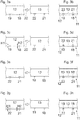
- Figures 3a-3h show schematic top views of the first rail 12 and second rail 13 with different arrangements of the spring means 18, 19 and the projections 21, 22.
- the first rail 12 is pushed onto the second rail 13 in the direction of arrow 20.
- Fig. 3a shows a first embodiment in which on the first rail 12 two longitudinally (L) spaced apart spring means 18, 19 with a substantially identical height and on the second rail 13 two longitudinally (L) spaced apart projections 21, 22 with a are arranged substantially identical in height.
- Figure 3b shows the connected state of the first and second rails 12, 13, the spring means 18, 19 and the projections 21, 22 resting against one another and thus limiting transverse movements of the two rails 12, 13 relative to one another.
- FIG. 3c a second embodiment is shown, in which on the first rail 12 two longitudinally (L) spaced apart spring means 18, 19 with different heights H1, H2 and on the second rail 13 two projections 21, 22 with different heights are arranged.
- This has the advantage that, when the first rail 12 is pushed onto the second rail 13 in the direction of arrow 20, the spring means 18 with a low height H2 can be moved past the projection 22 with a low height, preferably at a predetermined distance, and thus a low-friction retraction of the first rail 12 relative to second rail 13 is made possible.
- Fig. 3e shows a third embodiment, in which two longitudinally (L) spaced projections 21, 22 with an essentially identical height are arranged on the first rail 12 and two spring means 18, 19 with an essentially identical height are arranged on the second rail 13.
- Fig. 3g shows a fourth embodiment in which two longitudinally (L) spaced projections 21, 22 with different heights H1, H2 are arranged on the first rail 12 and two spring means 18, 19 protrude differently from the second rail 13 on the second rail 13 .
- Fig. 3h the connected state of the first and second rails 12, 13 is shown, the projection 21 arranged at the rear end region of the first rail 12 having a lower height H2 on the spring means 18 having a greater height and the front projection 22 having a greater height H1 on the spring means 19 having a lower height Height is applied.
- This embodiment also has the advantage that when the first rail 12 is pushed onto the second rail 13, the projection 21 with a lower height H2 does not interact in a dragging manner with the projection 19 of the second rail 13, so that the first rail 12 requires less force and less noise can be connected to the second rail 13.
- Figure 4a shows the first rail 12 to be fastened or fastened to the drawer 3 in a perspective view.
- the first rail 12 has in a cross section a U-profile with two perpendicular and mutually parallel side legs 12a, the spring means 18, 19 being arranged or formed on at least one side leg 12a.
- a locking device 23 shown schematically, by means of which the first and second rails 12, 13 can be releasably locked to one another, so that the first and second rails 12, 13 in the connected state in the longitudinal direction (L) are relative are immovable to each other.
- the locking device 23 can for example have a resilient locking lever arranged on the first rail 12 or on the drawer 3, which in the connected state of the first and second rails 12, 13 engages in a corresponding opening in the second rail 13.
- Figure 4b shows a side view of the first rail 12, the spring means 18, 19 preferably being arranged in the rear half of the first rail 12.
- Figure 4c FIG. 11 shows a cross section of the first rail 12 along the plane AA according to FIG Figure 4b , wherein the perpendicular and parallel side legs 12a of the first rail 12 can be seen.
- a projection 24 is arranged on a first side limb 12a and the spring means 18 is arranged on the opposite second side limb 12a, which in the rest state protrudes into a cavity delimited between the side limbs 12a.
- the spring means 18 can be pressed against the resilient force of the spring element 18 in the direction of a position flush with the side limb 12a.
- the first rail 12 also has a support leg 25, which runs horizontally in the assembly position, for the drawer bottom 6.
- Figure 5a shows the second rail 13 to be arranged or arranged on the pull-out drawer slide 4 in a perspective view.
- the cross section of the second rail 13 also has a U-profile with two perpendicular side legs 13a running parallel to one another, the second rail 13 being receivable in the U-profile of the first rail 12.
- the projections 21, 22 are arranged on at least one of the side legs 13a, it being preferably provided that the rear projection 21 is larger than the front projection 22.
- Figure 5b shows the second rail 13 in a cross section in the area of the projection 21 with a greater height H1.
- the height H1 of the larger projection 21 can be between 0.3 mm and 0.6 mm, preferably between 0.4 mm and 0.5 mm.
- Figure 5c shows the second rail 13 in a cross section in the area of the projection 22 with a lower height H2.
- the height H2 of the lower ledge 22 can be between 0.1 mm and 0.4 mm, preferably between 0.2 mm and 0.3 mm.
- Fig. 5d shows a cross-section of the connected state of the first and second rails 12, 13 in the region of the projection 21 of greater height H1, the rails 12, 13 together forming the drawer rail 11 for the drawer extension slide 4.
- the larger projection 21 of the second rail 13 rests on the spring means 18 of the first rail 12, while the opposite projection 24 of the first rail 12 rests on a side leg 13a of the second rail 13 without play, so that the second rail 13 is centered relative to the first rail 12 and transverse movements of the rails 12, 13 relative to one another are limited.
- Figure 5e shows a cross section of the connected state of the first and second rails 12, 13 in the region of the projection 22 with a lower height H2.
Abstract
Ladenschiene (11) für eine Schubladenausziehführung (4), mit:- einer an einer Schublade (3) zu befestigenden oder befestigten ersten Schiene (12),- einer an einer Korpusschiene (9) oder Mittelschiene (14) einer Schubladenausziehführung (4) anzuordnenden oder angeordneten zweiten Schiene (13),- wobei die erste Schiene (12) und die zweite Schiene (13) durch Aufschieben miteinander verbindbar sind, wobei an der ersten oder zweiten Schiene (12, 13) zumindest ein Federmittel (18, 19) angeordnet ist,wobei an der anderen Schiene (12, 13) wenigstens ein Vorsprung (21, 22, 24) angeordnet ist, dessen Lage an und/oder dessen Erstreckung entlang der anderen Schiene (12, 13) so gewählt ist, dass der wenigstens eine Vorsprung (21, 22, 24) im verbundenen Zustand der ersten und zweiten Schiene (12, 13) zur Begrenzung von Querbewegungen der zwei Schienen (12, 13) zueinander mit dem Federmittel (18, 19) zusammenwirkt.Drawer rail (11) for a drawer extension runner (4), with: - a first rail (12) to be fastened or fastened to a drawer (3), - one to be arranged on a body rail (9) or center rail (14) of a drawer extension runner (4) or arranged second rail (13), - wherein the first rail (12) and the second rail (13) can be connected to one another by being pushed on, with at least one spring means (18, 19) being arranged on the first or second rail (12, 13) is, with at least one projection (21, 22, 24) being arranged on the other rail (12, 13), the position of which on and / or its extension along the other rail (12, 13) is selected such that the at least one Projection (21, 22, 24) in the connected state of the first and second rails (12, 13) interacts with the spring means (18, 19) to limit transverse movements of the two rails (12, 13) with respect to one another.
Description
Die vorliegende Erfindung bezieht sich auf eine Ladenschiene für eine Schubladenausziehführung, mit:
- einer an einer Schublade zu befestigenden oder befestigten ersten Schiene,
- einer an einer Korpusschiene oder Mittelschiene einer Schubladenausziehführung anzuordnenden oder angeordneten zweiten Schiene,
- wobei die erste Schiene und die zweite Schiene durch Aufschieben miteinander verbindbar sind, wobei an der ersten oder zweiten Schiene zumindest ein Federmittel angeordnet ist.
- a first rail to be fastened or fastened to a drawer,
- a second rail to be arranged or arranged on a carcass rail or middle rail of a drawer extension runner,
- wherein the first rail and the second rail can be connected to one another by sliding them on, wherein at least one spring means is arranged on the first or second rail.
Im Weiteren betrifft die Erfindung eine Schubladenausziehführung mit zumindest einer Ladenschiene der zu beschreibenden Art sowie ein Möbel mit einem Möbelkorpus und einer relativ zum Möbelkorpus verfahrbar gelagerten Schublade, wobei die erste Schiene an der Schublade und die zweite Schiene am Möbelkorpus vormontiert sind, wobei die mit der Schublade verbundene erste Schiene durch Aufschieben auf die zweite Schiene mit der zweiten Schiene verbindbar ist.Furthermore, the invention relates to a drawer extension slide with at least one drawer rail of the type to be described and a piece of furniture with a furniture body and a drawer mounted so as to be movable relative to the furniture body, the first rail being preassembled on the drawer and the second rail being preassembled on the furniture body Drawer connected first rail can be connected to the second rail by sliding onto the second rail.
Bei der erstmaligen Montage einer Schublade an einer Schubladenausziehführung werden üblicherweise eine erste Schiene an der Schublade sowie eine Schubladenausziehführung mit einer zweiten Schiene am Möbelkorpus vormontiert. Im Anschluss daran wird die Schublade mit der ersten Schiene auf die zweite Schiene der Schubladenausziehführung aufgeschoben, bis eine selbsttätige Verriegelung zwischen der ersten Schiene und der zweiten Schiene erfolgt. Im Normalbetrieb sind die erste und die zweite Schiene relativ zueinander unverschiebbar angeordnet und bilden quasi eine zweiteilige Ladenschiene der Schubladenausziehführung aus. Durch ein an der ersten oder zweiten Schiene angeordnetes Federmittel, welches an der anderen Schiene abstützbar ist, kann im montierten Zustand der Schienen ein seitlich zur Längsrichtung der Schienen auftretendes Spiel zwischen der ersten und zweiten Schiene kompensiert werden. Das Federmittel kann beispielsweise als verbiegbare Federlasche oder Federzunge ausgebildet sein, welche aus dem Material einer Schiene ausgestanzt ist und durch welche das vorhandene Spiel zwischen der ersten und zweiten Schiene ausgleichbar ist. Je nach der Größe des vorhandenen Spiels zwischen der ersten und zweiten Schiene ist die Federlasche oder Federzunge relativ groß zu dimensionieren, wodurch neben einer unschönen Ausbildung auch die Gefahr einer Beschädigung des Federmittels, beispielsweise durch Abscheren, besteht.When a drawer is mounted on a drawer extension guide for the first time, a first rail on the drawer and a drawer extension guide with a second rail on the furniture body are usually preassembled. Subsequently, the drawer with the first rail is pushed onto the second rail of the drawer extension slide until an automatic locking occurs between the first rail and the second rail. In normal operation, the first and the second rails are arranged so as to be immovable relative to one another and form, as it were, a two-part drawer rail of the pull-out drawer. By a spring means arranged on the first or second rail, which spring means on the other rail can be supported, a play occurring laterally to the longitudinal direction of the rails between the first and second rails can be compensated for in the assembled state of the rails. The spring means can for example be designed as a bendable spring tab or spring tongue which is punched out of the material of a rail and by means of which the existing play between the first and second rails can be compensated. Depending on the size of the existing play between the first and second rails, the spring tab or spring tongue must be dimensioned relatively large, which means that, in addition to an unsightly design, there is also the risk of damage to the spring means, for example by shearing off.
In der
Aufgabe der vorliegenden Erfindung ist es, eine Ladenschiene der eingangs erwähnten Gattung unter Vermeidung der oben diskutierten Nachteile anzugeben.The object of the present invention is to provide a drawer rail of the type mentioned at the beginning while avoiding the disadvantages discussed above.
Dies wird erfindungsgemäß durch die Merkmale des Patentanspruchs 1 gelöst. Weitere vorteilhafte Ausführungen der Erfindung sind in den abhängigen Ansprüchen definiert.This is achieved according to the invention by the features of
Gemäß der Erfindung ist vorgesehen, dass an der anderen Schiene wenigstens ein Vorsprung angeordnet ist, dessen Lage an und/oder dessen Erstreckung entlang der anderen Schiene so gewählt ist, dass der wenigstens eine Vorsprung im verbundenen Zustand der ersten und zweiten Schiene zur Begrenzung von Querbewegungen der zwei Schienen zueinander mit dem Federmittel zusammenwirkt.According to the invention it is provided that at least one projection is arranged on the other rail, the position of which on and / or its extension along the other rail is selected so that the at least one projection in the connected state of the first and second rails to limit transverse movements the two rails interacts with one another with the spring means.
Mit anderen Worten liegt im verbundenen Zustand der beiden Schienen das Federmittel einer Schiene am Vorsprung der anderen Schiene an, sodass das Federmittel mit einer reduzierten, beispielsweise etwa der halben, Bauhöhe an einer Schiene ausgebildet werden kann. Auf diese Weise kann die Gefahr einer Beschädigung des Federmittels und der erforderliche Materialbedarf des Federmittels verringert werden kann. Das verbleibende Differenzspiel zwischen den Schienen wird also durch den an der anderen Schiene angeordneten Vorsprung ausgeglichen, welcher im montierten Zustand der Schienen am Federelement spielfrei anliegt.In other words, in the connected state of the two rails, the spring means of one rail rests on the projection of the other rail, so that the spring means can be designed with a reduced, for example approximately half, structural height on a rail. In this way, the risk of damage to the spring means and the necessary material requirements for the spring means can be reduced. The remaining difference play between the rails is thus compensated for by the projection arranged on the other rail, which in the assembled state of the rails rests on the spring element without play.
Gemäß einem Ausführungsbeispiel ist die erste Schiene ausgehend von einem vorderen Endbereich der zweiten Schiene zu einem hinteren Endbereich der zweiten Schiene aufschiebbar, wobei der wenigstens eine Vorsprung nur über einen dem hinteren Endbereich der zweiten Schiene unmittelbar vorgelagerten Teilbereich mit dem zumindest einen Federmittel zusammenwirkt. Dies hat den besonderen Vorteil, dass die Schublade mit der ersten Schiene über einen Großteil des Aufschiebeweges mit einem reduzierten Reibungswiderstand relativ zur zweiten Schiene bewegbar ist, ohne dass dabei ein an einer Schiene schleifendes Federmittel den Reibungswiderstand erhöht. Erst gegen Ende des Aufschiebeweges treten das Federmittel und der Vorsprung miteinander in Kontakt und kompensieren durch gegenseitiges Aneinanderliegen das Spiel zwischen den beiden Schienen.According to one embodiment, the first rail can be pushed open from a front end region of the second rail to a rear end region of the second rail, the at least one projection interacting with the at least one spring means only over a partial region immediately in front of the rear end region of the second rail. This has the particular advantage that the drawer with the first rail can be moved relative to the second rail over a large part of the sliding path with reduced frictional resistance, without a spring means dragging against a rail increasing the frictional resistance. Only towards the end of the sliding path do the spring means and the projection come into contact with one another and compensate for the play between the two rails by resting against one another.
Die erste Schiene und die zweite Schiene können jeweils zumindest einen in Längsrichtung der Schienen verlaufenden Seitenschenkel aufweisen, wobei das zumindest eine Federmittel und der wenigstens eine Vorsprung jeweils an einem Seitenschenkel der Schienen angeordnet oder ausgebildet sind. Dabei kann vorgesehen sein, dass das zumindest eine Federmittel und der wenigstens eine Vorsprung jeweils von den Seitenschenkeln der Schienen quer abstehen.The first rail and the second rail can each have at least one side leg running in the longitudinal direction of the rails, the at least one spring means and the at least one projection being arranged or formed on a side leg of the rails. It can be provided that the at least one spring means and the at least one projection each protrude transversely from the side legs of the rails.
Bei einer konstruktiv einfachen Ausführung kann vorgesehen sein, dass das zumindest eine Federmittel und/oder der wenigstens eine Vorsprung mit den Schienen einstückig ausgebildet ist oder sind.In a structurally simple embodiment, it can be provided that the at least one spring means and / or the at least one projection is or are formed in one piece with the rails.
Das zumindest eine Federmittel kann in einer quer zur Längsrichtung der Schiene verlaufenden Richtung elastisch verbiegbar oder reversibel verformbar ausgebildet sein, wobei vorzugsweise vorgesehen ist, dass das zumindest eine Federmittel in Form einer Federlasche oder Federzunge an einer der Schienen ausgebildet ist. Die Federlasche oder Federzunge kann beispielsweise aus einem metallischen Material einer Schiene ausgestanzt sein. Alternativ ist es möglich, dass das Federmittel zumindest ein mechanisches Federelement (beispielsweise eine Druckfeder) aufweist.The at least one spring means can be designed to be elastically bendable or reversibly deformable in a direction running transversely to the longitudinal direction of the rail, whereby it is preferably provided that the at least one spring means is designed in the form of a spring tab or spring tongue on one of the rails. The spring tab or spring tongue can, for example, be punched out of a metallic material of a rail. Alternatively, it is possible for the spring means to have at least one mechanical spring element (for example a compression spring).
Der wenigstens eine Vorsprung kann in einer quer zur Längsrichtung der Schiene verlaufenden Richtung im Wesentlichen starr ausgebildet sein, wobei vorzugsweise vorgesehen ist, dass der wenigstens eine Vorsprung in Form einer Prägung an einer der Schienen ausgebildet ist. Alternativ ist es möglich, dass der Vorsprung ebenfalls elastisch nachgiebig ausgebildet ist und/oder an einer Schiene (beispielsweise durch Anschrauben oder Verkleben) befestigt ist.The at least one protrusion can be designed essentially rigid in a direction running transversely to the longitudinal direction of the rail, whereby it is preferably provided that the at least one protrusion is designed in the form of an embossing on one of the rails. Alternatively, it is possible that the projection is also designed to be elastically flexible and / or is attached to a rail (for example by screwing or gluing).
Gemäß einem Ausführungsbeispiel kann vorgesehen sein, dass an der ersten oder zweiten Schiene zumindest zwei in Längsrichtung der Schiene voneinander beabstandete Federmittel angeordnet sind, welche im verbundenen Zustand der ersten und zweiten Schiene mit zumindest zwei in Längsrichtung voneinander beabstandeten Vorsprüngen der anderen Schiene zusammenwirken. Die zwei Schienen sind dann zumindest in jenen Bereichen, in welchen die zumindest zwei voneinander in Längsrichtung beabstandeten Federmittel an den ihnen zugeordneten Vorsprüngen anliegen, in einer quer zur Längsrichtung verlaufenden Richtung spielfrei zueinander angeordnet.According to one embodiment it can be provided that at least two spring means are arranged on the first or second rail, spaced apart from one another in the longitudinal direction of the rail, which spring means, in the connected state of the first and second rails, are arranged with at least two in the longitudinal direction from one another cooperate spaced projections of the other rail. The two rails are then at least in those areas in which the at least two spring means spaced apart from one another in the longitudinal direction bear against the projections assigned to them, in a direction running transversely to the longitudinal direction without play relative to one another.
Die zumindest zwei Federmittel und/oder die zumindest zwei Vorsprünge können jeweils eine unterschiedliche Höhe aufweisen. Gemäß einer ersten Variante kann vorgesehen sein, dass beim Aufschieben der ersten Schiene auf die zweite Schiene ein Federmittel mit geringerer Höhe an einem Vorsprung mit geringerer Höhe vorbeibewegbar ist, wobei im verbundenen Zustand der ersten und zweiten Schiene das Federmittel geringerer Höhe an einem Vorsprung mit größerer Höhe anliegt.The at least two spring means and / or the at least two projections can each have a different height. According to a first variant, it can be provided that when the first rail is pushed onto the second rail, a spring means with a lower height can be moved past a projection with a lower height, wherein in the connected state of the first and second rails the spring means with a lower height can be moved past a projection with a greater height Height is applied.
Gemäß einer zweiten Variante kann vorgesehen sein, dass beim Aufschieben der ersten Schiene auf die zweite Schiene ein Vorsprung mit geringerer Höhe an einem Federmittel mit geringerer Höhe vorbeibewegbar ist, wobei im verbundenen Zustand der ersten und zweiten Schiene der Vorsprung mit geringerer Höhe an einem Federmittel mit größerer Höhe anliegt.According to a second variant, it can be provided that when the first rail is pushed onto the second rail, a projection with a lower height can be moved past a spring means with a lower height, the lower-height projection with a spring means in the connected state of the first and second rails greater height.
Diese beiden Varianten haben den Vorteil, dass die Schublade auf die zweite Schiene für eine Person leichtgängig aufschiebbar ist, da der Vorsprung und das Federmittel, vorzugsweise unter Bildung eines Spaltes oder allenfalls nur mit einer geringen Reibung, aneinander vorbeibewegbar sind und erst im verbundenen Zustand oder unmittelbar vor Erreichen des verbundenen Zustandes eine spielfreie Verbindung zwischen den beiden Schienen durch die an den Federmitteln anliegenden Vorsprünge hergestellt wird.These two variants have the advantage that the drawer can easily be slid onto the second rail for one person, since the projection and the spring means can be moved past one another, preferably with the formation of a gap or at most only with little friction, and only in the connected state or immediately before the connected state is reached, a backlash-free connection between the two rails is established by the projections resting on the spring means.
Die erfindungsgemäße Schubladenausziehführung weist eine an einem Möbelkorpus zu befestigende Korpusschiene und zumindest eine Ladenschiene der beschriebenen Art auf, wobei die Ladenschiene relativ zur Korpusschiene verfahrbar gelagert ist. Um einen Vollauszug der Schublade relativ zum Möbelkorpus zu ermöglichen, kann eine zusätzliche Mittelschiene vorgesehen sein, welche zwischen der Korpusschiene und der Ladenschiene verschiebbar gelagert ist.The pull-out drawer slide according to the invention has a carcass rail to be fastened to a furniture carcass and at least one drawer rail of the type described, the drawer rail being relative to the carcass rail is movably mounted. In order to enable the drawer to be fully extended relative to the furniture carcass, an additional central rail can be provided, which is mounted displaceably between the carcass rail and the drawer rail.
Das erfindungsgemäße Möbel weist einen Möbelkorpus und eine relativ zum Möbelkorpus verfahrbar gelagerte Schublade auf, wobei die erste Schiene an der Schublade und die zweite Schiene am Möbelkorpus vormontiert sind, wobei die mit der Schublade verbundene erste Schiene durch Aufschieben auf die zweite Schiene mit der zweiten Schiene verbindbar ist.The furniture according to the invention has a furniture body and a drawer mounted so as to be movable relative to the furniture body, the first rail being preassembled on the drawer and the second rail being preassembled on the furniture body, the first rail connected to the drawer being pushed onto the second rail with the second rail is connectable.
Weitere Einzelheiten und Vorteile der vorliegenden Erfindung werden anhand der nachfolgenden Figurenbeschreibung erläutert.
- Fig. 1
- zeigt eine perspektivische Darstellung eines Möbels mit Schubladen, welche durch Schubladenausziehführungen relativ zu einem Möbelkorpus verfahrbar gelagert sind,
- Fig. 2a, 2b
- zeigen die an der Schubladenausziehführung zu befestigende Schublade sowie die an der Schubladenausziehführung befestigte Schublade in perspektivischen Ansichten,
- Fig. 3a-3h
- zeigen schematische Draufsichten auf die erste und zweite Schiene mit unterschiedlichen Anordnungen der Federmittel und der Vorsprünge,
- Fig. 4a-4c
- zeigen die an der Schublade zu befestigende oder befestigte erste Schiene in verschiedenen Ansichten,
- Fig. 5a-5e
- zeigen verschiedene Ansichten der an der Schubladenausziehführung anzuordnenden oder angeordneten zweiten Schiene sowie zwei Ansichten der miteinander verbundenen Schienen in einem Querschnitt.
- Fig. 1
- shows a perspective view of a piece of furniture with drawers, which are mounted so that they can be moved relative to a furniture body by means of drawer extension guides,
- Figures 2a, 2b
- show the drawer to be fastened to the drawer extension runner and the drawer fastened to the drawer extension runner in perspective views,
- Figures 3a-3h
- show schematic top views of the first and second rails with different arrangements of the spring means and the projections,
- Figures 4a-4c
- show the first rail to be fastened or fastened to the drawer in different views,
- Figures 5a-5e
- show different views of the second rail to be arranged or arranged on the pull-out drawer slide, as well as two views of the rails connected to one another in a cross section.
Die Korpusschiene 9 der Schubladenausziehführung 4 wird über die Befestigungsabschnitte 10a, 10b am Möbelkorpus 2 montiert, wobei die zweite Schiene 13 der Ladenschiene 11 und die Mittelschiene 14 relativ zur stationären Korpusschiene 9 verschiebbar gelagert sind. Die Schublade 3 wird an der zweiten Schiene 13 montiert, indem die an den beiden Seitenwänden 7 der Schublade 3 angeordneten ersten Schienen 12 auf die zweiten Schienen 13 der Schubladenausziehführungen 4 in Richtung des eingezeichneten Pfeils 20 aufgeschoben werden.The
In
In
Claims (15)
Applications Claiming Priority (3)
| Application Number | Priority Date | Filing Date | Title |
|---|---|---|---|
| ATA50097/2018A AT520734B1 (en) | 2018-02-01 | 2018-02-01 | Drawer rail for a drawer pull-out guide |
| EP18829191.8A EP3745918B1 (en) | 2018-02-01 | 2018-12-21 | Loading rail for a pull-out guide for a drawer |
| PCT/AT2018/060317 WO2019148216A1 (en) | 2018-02-01 | 2018-12-21 | Loading rail for a pull-out guide for a drawer |
Related Parent Applications (1)
| Application Number | Title | Priority Date | Filing Date |
|---|---|---|---|
| EP18829191.8A Division EP3745918B1 (en) | 2018-02-01 | 2018-12-21 | Loading rail for a pull-out guide for a drawer |
Publications (1)
| Publication Number | Publication Date |
|---|---|
| EP3922137A1 true EP3922137A1 (en) | 2021-12-15 |
Family
ID=64901797
Family Applications (2)
| Application Number | Title | Priority Date | Filing Date |
|---|---|---|---|
| EP18829191.8A Active EP3745918B1 (en) | 2018-02-01 | 2018-12-21 | Loading rail for a pull-out guide for a drawer |
| EP21190138.4A Withdrawn EP3922137A1 (en) | 2018-02-01 | 2018-12-21 | Drawer rail for drawer extension guide |
Family Applications Before (1)
| Application Number | Title | Priority Date | Filing Date |
|---|---|---|---|
| EP18829191.8A Active EP3745918B1 (en) | 2018-02-01 | 2018-12-21 | Loading rail for a pull-out guide for a drawer |
Country Status (7)
| Country | Link |
|---|---|
| US (1) | US11464333B2 (en) |
| EP (2) | EP3745918B1 (en) |
| JP (1) | JP7065983B2 (en) |
| CN (1) | CN111655078B (en) |
| AT (1) | AT520734B1 (en) |
| ES (1) | ES2898860T3 (en) |
| WO (1) | WO2019148216A1 (en) |
Families Citing this family (2)
| Publication number | Priority date | Publication date | Assignee | Title |
|---|---|---|---|---|
| CN112586916A (en) * | 2020-12-05 | 2021-04-02 | 海宁金茂五金有限公司 | Composite sliding rail |
| CN114468628A (en) * | 2022-01-24 | 2022-05-13 | 无锡海达尔精密滑轨股份有限公司 | Sliding rail assembly |
Citations (9)
| Publication number | Priority date | Publication date | Assignee | Title |
|---|---|---|---|---|
| CH568735A5 (en) * | 1973-05-19 | 1975-11-14 | Thoma Robert Ohg | Writing desk drawer with safety retaining catch - is released when required with pencil or similar article |
| US4119377A (en) * | 1976-07-16 | 1978-10-10 | Standard Precision, Inc. | Self-aligning drawer slide tab |
| DE9402042U1 (en) * | 1994-02-08 | 1994-03-31 | Hettich Paul Gmbh & Co | Side frame of a drawer |
| EP1316275A1 (en) * | 2001-12-03 | 2003-06-04 | Miguel Angel Rioja Calvo | System for the assembly/disassembly between two sliding adjustable parts placed against each other |
| EP1483984A1 (en) | 2003-06-05 | 2004-12-08 | Grass AG | Drawer slide |
| ES2239249T3 (en) * | 2001-08-17 | 2005-09-16 | Accuride International, Inc. | SLIDE GUIDE WITH GUIDE TONGUE. |
| DE202006000519U1 (en) * | 2006-01-13 | 2006-05-24 | King Slide Works Co., Ltd., Lu-Chu Hsiang | Locking device for three ply guiding set, has two latches with respective rear ends and enlarged front ends, and middle rail, coupled with inner rail, engaged with rear end in one of notches by related latch |
| CN104873012A (en) * | 2014-02-28 | 2015-09-02 | 日本电气株式会社 | Slide Rail And Equipment Mounting Rack |
| JP6433779B2 (en) * | 2014-12-18 | 2018-12-05 | 日本アキュライド株式会社 | Brake device for slide rail |
Family Cites Families (41)
| Publication number | Priority date | Publication date | Assignee | Title |
|---|---|---|---|---|
| AT379497B (en) * | 1981-10-30 | 1986-01-10 | Blum Gmbh Julius | EXTENSION GUIDE SET FOR DRAWERS OD. DGL. |
| DE8307469U1 (en) * | 1983-03-15 | 1983-10-13 | Bbp-Kunststoffwerk Marbach Baier & Co, 7142 Marbach | PLASTIC DRAWER FOR FURNITURE |
| DE8710830U1 (en) * | 1987-08-07 | 1987-09-24 | Paul Hettich Gmbh & Co, 4983 Kirchlengern, De | |
| US5281021A (en) * | 1989-10-06 | 1994-01-25 | Julius Blum Gesellschaft M.B.H. | Arrangement for removably mounting a drawer to pull-out rails of drawer guide assemblies |
| CA2080351A1 (en) * | 1991-02-12 | 1992-08-13 | Erich Rock | Extension guide assembly for a drawer |
| DE9215250U1 (en) * | 1992-11-10 | 1993-02-25 | Grass Ag, Hoechst, Vorarlberg, At | |
| AT401713B (en) * | 1993-06-29 | 1996-11-25 | Blum Gmbh Julius | DIFFERENTIAL EXTRACT FOR DRAWERS OD. DGL. |
| US5980007A (en) * | 1997-04-23 | 1999-11-09 | Accuride International, Inc. | Drawer slide undermount bracket with flexible locking tab |
| US5951132A (en) * | 1997-11-18 | 1999-09-14 | Jonathan Manufacturing Corp. | Multi-use snap-part body for slider |
| AT409072B (en) * | 1998-06-24 | 2002-05-27 | Blum Gmbh Julius | drawer |
| DE19944639A1 (en) * | 1999-09-17 | 2001-03-22 | Hettich Paul Gmbh & Co | Fastening arrangement |
| AT410504B (en) * | 2000-01-14 | 2003-05-26 | Blum Gmbh Julius | LOCKING AND / OR PULL-IN DEVICE FOR MOVABLE FURNITURE PARTS |
| US6257683B1 (en) * | 2000-03-13 | 2001-07-10 | Jun-Long Yang | Detachable rail for a drawer track |
| TW589967U (en) * | 2002-05-10 | 2004-06-01 | King Slide Works Co Ltd | Positioning track assembly for drawer |
| MY131063A (en) * | 2002-05-17 | 2007-07-31 | Harn Marketing Sdn Bhd | Guide rails pull-out drawer/equipment |
| DE102006018426A1 (en) * | 2006-04-20 | 2007-10-25 | BSH Bosch und Siemens Hausgeräte GmbH | Multi-part household appliance |
| ES2344230T3 (en) * | 2006-12-15 | 2010-08-20 | Harn Marketing Sdn. Bhd. | CORNER ACCESSORY. |
| MY151706A (en) * | 2009-08-12 | 2014-06-30 | Harn Marketing Sdn Bhd | Drawer assembly |
| JP5290086B2 (en) * | 2009-08-18 | 2013-09-18 | Thk株式会社 | Exercise guidance device |
| AT510773B1 (en) * | 2010-11-23 | 2014-09-15 | Blum Gmbh Julius | Drawer arrangement with a container rail preassembled on a drawer container |
| AT511081B1 (en) * | 2011-05-05 | 2012-09-15 | Blum Gmbh Julius | ARRANGEMENT WITH A DRAWER AND WITH A DRAWER EXTRACTOR |
| US9198322B2 (en) * | 2013-01-23 | 2015-11-24 | Dot Hill Systems Corporation | Compliant drawer latch assembly |
| TW201442672A (en) | 2013-05-14 | 2014-11-16 | Hon Hai Prec Ind Co Ltd | Slide |
| CN203302662U (en) * | 2013-05-25 | 2013-11-27 | 陈明开 | Drawer guide rail rapid disassembling and assembling structure |
| US9743765B2 (en) * | 2013-07-02 | 2017-08-29 | Stephen John Lawson | Customizable modular storage unit organizer apparatus, system and method of using same |
| EP2901891B1 (en) * | 2014-01-29 | 2016-12-07 | King Slide Works Co., Ltd. | Slide assembly |
| DE102014203677A1 (en) * | 2014-02-28 | 2015-09-17 | BSH Hausgeräte GmbH | Domestic refrigerator with a shelf and a shelf mounted on the fixture |
| AT515527B1 (en) * | 2014-05-14 | 2015-10-15 | Blum Gmbh Julius | Drawer side wall |
| DE202014104929U1 (en) * | 2014-10-16 | 2016-01-19 | Grass Gmbh | Frame for a drawer with a frame body and drawer and furniture with a drawer |
| DE102015203436B4 (en) * | 2015-02-26 | 2020-07-02 | BSH Hausgeräte GmbH | Extractor hood with pull-out body |
| TWI548369B (en) * | 2015-10-06 | 2016-09-11 | King Slide Works Co Ltd | Mounting part for slide rail assembly |
| TWI548370B (en) * | 2015-11-12 | 2016-09-11 | 川湖科技股份有限公司 | Quick release mechanism for drawer slide parts |
| TWI539915B (en) * | 2015-11-12 | 2016-07-01 | 川湖科技股份有限公司 | Drawer parts and mounting fitting thereof |
| TWI538638B (en) * | 2015-11-12 | 2016-06-21 | 川湖科技股份有限公司 | Drive mechanism and method for furniture parts |
| US10314398B2 (en) * | 2015-12-17 | 2019-06-11 | Grass America, Inc. | Pull-out guide for the guidance of a drawer |
| AT518049B1 (en) * | 2015-12-22 | 2017-07-15 | Blum Gmbh Julius | drawer arrangement |
| AT518980B1 (en) * | 2016-10-28 | 2018-03-15 | Blum Gmbh Julius | drawer |
| TWI629956B (en) * | 2017-05-04 | 2018-07-21 | 川湖科技股份有限公司 | Slide rail assembly |
| TWI638624B (en) * | 2017-06-23 | 2018-10-21 | 川湖科技股份有限公司 | Slide rail assembly |
| DE102017119909A1 (en) * | 2017-08-30 | 2019-02-28 | Paul Hettich Gmbh & Co. Kg | Pull-out guide for relative to a furniture body movable furniture parts, drawer and furniture or household appliance |
| CN108720379B (en) * | 2018-05-25 | 2021-04-23 | 海尔智家股份有限公司 | Drawer sliding rail assembly and refrigeration equipment |
-
2018
- 2018-02-01 AT ATA50097/2018A patent/AT520734B1/en active
- 2018-12-21 EP EP18829191.8A patent/EP3745918B1/en active Active
- 2018-12-21 ES ES18829191T patent/ES2898860T3/en active Active
- 2018-12-21 JP JP2020542017A patent/JP7065983B2/en active Active
- 2018-12-21 EP EP21190138.4A patent/EP3922137A1/en not_active Withdrawn
- 2018-12-21 CN CN201880088283.6A patent/CN111655078B/en active Active
- 2018-12-21 WO PCT/AT2018/060317 patent/WO2019148216A1/en unknown
-
2020
- 2020-07-28 US US16/940,665 patent/US11464333B2/en active Active
Patent Citations (9)
| Publication number | Priority date | Publication date | Assignee | Title |
|---|---|---|---|---|
| CH568735A5 (en) * | 1973-05-19 | 1975-11-14 | Thoma Robert Ohg | Writing desk drawer with safety retaining catch - is released when required with pencil or similar article |
| US4119377A (en) * | 1976-07-16 | 1978-10-10 | Standard Precision, Inc. | Self-aligning drawer slide tab |
| DE9402042U1 (en) * | 1994-02-08 | 1994-03-31 | Hettich Paul Gmbh & Co | Side frame of a drawer |
| ES2239249T3 (en) * | 2001-08-17 | 2005-09-16 | Accuride International, Inc. | SLIDE GUIDE WITH GUIDE TONGUE. |
| EP1316275A1 (en) * | 2001-12-03 | 2003-06-04 | Miguel Angel Rioja Calvo | System for the assembly/disassembly between two sliding adjustable parts placed against each other |
| EP1483984A1 (en) | 2003-06-05 | 2004-12-08 | Grass AG | Drawer slide |
| DE202006000519U1 (en) * | 2006-01-13 | 2006-05-24 | King Slide Works Co., Ltd., Lu-Chu Hsiang | Locking device for three ply guiding set, has two latches with respective rear ends and enlarged front ends, and middle rail, coupled with inner rail, engaged with rear end in one of notches by related latch |
| CN104873012A (en) * | 2014-02-28 | 2015-09-02 | 日本电气株式会社 | Slide Rail And Equipment Mounting Rack |
| JP6433779B2 (en) * | 2014-12-18 | 2018-12-05 | 日本アキュライド株式会社 | Brake device for slide rail |
Also Published As
| Publication number | Publication date |
|---|---|
| JP7065983B2 (en) | 2022-05-12 |
| ES2898860T3 (en) | 2022-03-09 |
| JP2021511908A (en) | 2021-05-13 |
| EP3745918A1 (en) | 2020-12-09 |
| US11464333B2 (en) | 2022-10-11 |
| WO2019148216A1 (en) | 2019-08-08 |
| CN111655078A (en) | 2020-09-11 |
| AT520734A4 (en) | 2019-07-15 |
| AT520734B1 (en) | 2019-07-15 |
| CN111655078B (en) | 2022-01-14 |
| US20200352327A1 (en) | 2020-11-12 |
| EP3745918B1 (en) | 2021-08-11 |
Similar Documents
| Publication | Publication Date | Title |
|---|---|---|
| EP2642897B1 (en) | Coupling device for drawers | |
| EP2916688B1 (en) | Drawer pull out guide | |
| DE3832701A1 (en) | FASTENING ARRANGEMENT FOR THE GUIDE RAIL OF A EXTENSION GUIDE | |
| AT511081A4 (en) | ARRANGEMENT WITH A DRAWER AND WITH A DRAWER EXTRACTOR | |
| WO2013029067A1 (en) | Drawer | |
| EP0011675A1 (en) | Slide for drawers or the like | |
| EP3092919B1 (en) | Guide device for guiding a movable part of a piece of furniture relative to the body of a piece of furniture | |
| EP3745918B1 (en) | Loading rail for a pull-out guide for a drawer | |
| EP0957714B1 (en) | Flush-mounted extraction guide for drawers etc. | |
| EP0780071A2 (en) | Drawer with ball drawer slide | |
| EP1513429B1 (en) | Arrangement for connecting a drawer frame to the bottom of a drawer | |
| EP3434144B1 (en) | Slide rail | |
| AT521105B1 (en) | Drawer rail for a drawer pull-out guide | |
| EP3727087A1 (en) | Drawer pull-out guide | |
| AT515689B1 (en) | drawer | |
| EP3838068A1 (en) | Drawer slide guide | |
| EP2979581B1 (en) | Guide device for guiding a movable part of a piece of furniture relative to the body of a piece of furniture | |
| EP2716182A1 (en) | Extension guide for a pull-out furniture part extendible from a furniture body | |
| AT395809B (en) | EXTENSION GUIDE FOR DRAWERS AND THE LIKE | |
| DE102017128747B4 (en) | Movement mechanism for a guidance system | |
| DE102013009193B3 (en) | Height-adjustable piece of furniture with a sliding element and method for its production | |
| DE4411921A1 (en) | Sliding rail system for drawer | |
| AT402600B (en) | Runner (withdrawal guide), especially under-base runner, for drawers, compartments or the like | |
| DE20321394U1 (en) | Drawer rail system comprises two rails attached to carcass, rails attached to drawer bottom and intermediate rails with roller at its front end, two rollers one above the other at its center and one roller at its rear end | |
| AT520817A4 (en) | Arrangement of pull-out guide, rail synchronization device and driver |
Legal Events
| Date | Code | Title | Description |
|---|---|---|---|
| PUAI | Public reference made under article 153(3) epc to a published international application that has entered the european phase |
Free format text: ORIGINAL CODE: 0009012 |
|
| STAA | Information on the status of an ep patent application or granted ep patent |
Free format text: STATUS: THE APPLICATION HAS BEEN PUBLISHED |
|
| AC | Divisional application: reference to earlier application |
Ref document number: 3745918 Country of ref document: EP Kind code of ref document: P |
|
| AK | Designated contracting states |
Kind code of ref document: A1 Designated state(s): AL AT BE BG CH CY CZ DE DK EE ES FI FR GB GR HR HU IE IS IT LI LT LU LV MC MK MT NL NO PL PT RO RS SE SI SK SM TR |
|
| B565 | Issuance of search results under rule 164(2) epc |
Effective date: 20211020 |
|
| STAA | Information on the status of an ep patent application or granted ep patent |
Free format text: STATUS: THE APPLICATION IS DEEMED TO BE WITHDRAWN |
|
| 18D | Application deemed to be withdrawn |
Effective date: 20220616 |