EP2642897B1 - Coupling device for drawers - Google Patents
Coupling device for drawers Download PDFInfo
- Publication number
- EP2642897B1 EP2642897B1 EP11788006.2A EP11788006A EP2642897B1 EP 2642897 B1 EP2642897 B1 EP 2642897B1 EP 11788006 A EP11788006 A EP 11788006A EP 2642897 B1 EP2642897 B1 EP 2642897B1
- Authority
- EP
- European Patent Office
- Prior art keywords
- rail
- drawer
- extendable
- releasably
- spring tongue
- Prior art date
- Legal status (The legal status is an assumption and is not a legal conclusion. Google has not performed a legal analysis and makes no representation as to the accuracy of the status listed.)
- Active
Links
- 230000008878 coupling Effects 0.000 title claims description 18
- 238000010168 coupling process Methods 0.000 title claims description 18
- 238000005859 coupling reaction Methods 0.000 title claims description 18
- 238000003780 insertion Methods 0.000 claims description 4
- 230000037431 insertion Effects 0.000 claims description 4
- 239000004033 plastic Substances 0.000 claims description 4
- 238000010276 construction Methods 0.000 claims description 2
- 210000002105 tongue Anatomy 0.000 description 22
- 238000005452 bending Methods 0.000 description 2
- 238000009434 installation Methods 0.000 description 2
- 230000008859 change Effects 0.000 description 1
- 238000004140 cleaning Methods 0.000 description 1
- 230000007423 decrease Effects 0.000 description 1
- 230000001419 dependent effect Effects 0.000 description 1
- 230000000881 depressing effect Effects 0.000 description 1
- 238000006073 displacement reaction Methods 0.000 description 1
- 230000000694 effects Effects 0.000 description 1
- 238000002347 injection Methods 0.000 description 1
- 239000007924 injection Substances 0.000 description 1
- 238000001746 injection moulding Methods 0.000 description 1
- 230000009467 reduction Effects 0.000 description 1
- 239000000243 solution Substances 0.000 description 1
- 239000003351 stiffener Substances 0.000 description 1
- 239000012815 thermoplastic material Substances 0.000 description 1
- 230000003313 weakening effect Effects 0.000 description 1
Images


Classifications
-
- A—HUMAN NECESSITIES
- A47—FURNITURE; DOMESTIC ARTICLES OR APPLIANCES; COFFEE MILLS; SPICE MILLS; SUCTION CLEANERS IN GENERAL
- A47B—TABLES; DESKS; OFFICE FURNITURE; CABINETS; DRAWERS; GENERAL DETAILS OF FURNITURE
- A47B88/00—Drawers for tables, cabinets or like furniture; Guides for drawers
- A47B88/40—Sliding drawers; Slides or guides therefor
- A47B88/423—Fastening devices for slides or guides
- A47B88/427—Fastening devices for slides or guides at drawer side
-
- A—HUMAN NECESSITIES
- A47—FURNITURE; DOMESTIC ARTICLES OR APPLIANCES; COFFEE MILLS; SPICE MILLS; SUCTION CLEANERS IN GENERAL
- A47B—TABLES; DESKS; OFFICE FURNITURE; CABINETS; DRAWERS; GENERAL DETAILS OF FURNITURE
- A47B88/00—Drawers for tables, cabinets or like furniture; Guides for drawers
- A47B88/40—Sliding drawers; Slides or guides therefor
- A47B88/483—Sliding drawers; Slides or guides therefor with single extensible guides or parts
-
- A—HUMAN NECESSITIES
- A47—FURNITURE; DOMESTIC ARTICLES OR APPLIANCES; COFFEE MILLS; SPICE MILLS; SUCTION CLEANERS IN GENERAL
- A47B—TABLES; DESKS; OFFICE FURNITURE; CABINETS; DRAWERS; GENERAL DETAILS OF FURNITURE
- A47B88/00—Drawers for tables, cabinets or like furniture; Guides for drawers
- A47B88/50—Safety devices or the like for drawers
- A47B88/57—Safety devices or the like for drawers preventing complete withdrawal of the drawer
Definitions
- the invention relates to a drawer extension with a device of the type to be described and a drawer, which is to be connected via such a device with an extendable rail a drawer extension.
- coupling devices are known, by means of which a drawer in its entirety can be mounted or dismounted on an extendable rail of a drawer extension guide, so that the drawer can be completely detached from the drawer extension guide, for example for cleaning purposes, and then re-attached.
- the coupling of the drawer with the pull-out can be done automatically by a resilient locking part of the device locked with a predetermined connection point of the pull-out rail.
- the drawer extension guide is first preassembled on the furniture, whereupon the drawer to be fastened is pushed onto the pull-out rail located in the closed position, until the drawer is automatically latched to the pull-out rail via the latching part.
- the disassembly of the drawer relative to the pull-out can also be done without tools by a designed for manual operation grip part is actuated, whereby the locking part is released from the latch and the drawer can then be removed.
- a drawer extension guide is described with a running rail, at the front end of a Einschubbegrenzer is arranged with a form spring. This ensures that the running rail can only be moved so far in the insertion direction until a front end of the form spring bears against the middle rail of the drawer extension guide, wherein the detent of a coupling device engages in a recess provided in the running rail and moves the form spring out of the displacement of the center rail becomes. This ensures that the running rail is reliably coupled to the sliding furniture part.
- a device for releasably coupling a drawer to a drawer extension guide wherein a hook part can be latched to corresponding webs of the pull-out rail. By manual pressure on an elastic part of the hook part can be unlocked by the webs, whereby the drawer can be separated from the pull-out rail.
- the pull-out during installation of the drawer occupies a more or less predetermined position to the locking part, so that the locking part can lock as intended with the predetermined connection point of the extendable rail. If this position is not within a predetermined tolerance range, it would be possible for parts of the coupling device injection molded from plastic to be damaged by the sliding of the drawer onto the pull-out rail or even to be sheared off completely therefrom.
- An apparatus according to the preamble of claim 1 is made US 20040227440 A1 known.
- Object of the present invention is therefore to propose a device of the type mentioned above while avoiding the above drawback.
- the counter-holding part has at least one spring tongue.
- the spring tongue form, together with the opposite latching part, an insertion funnel for the front end of the pull-out rail, wherein the width of the insertion funnel decreases in the mounting position in the direction of the drawer front panel.
- the spring tongue may have a, preferably curved, inlet bevel through which the extendable rail can be pressed against the latching part when it is pushed into the device. It can also be provided that the spring tongue and / or the locking part is designed to be resilient in a direction transverse to the longitudinal direction of the rail or are so that any occurring position tolerances of the drawer relative to the extendable rail can be compensated. Depending on the installation position of the device, the spring tongue and / or the locking part may be resilient in the horizontal or in the vertical direction.
- the drawer extension according to the invention has a to be fastened to a furniture body carcass rail, at least one displaceable relative to the carcass rail mounted pull-out rail and a device of the type in question through which a drawer is releasably connected to the pull-out of Schubladenauszieh Installation.
- the locking part and the handle part are integrally formed. It is particularly advantageous if the device is made in one piece from plastic in its entirety. Such a device can thus be produced in a simple manner in the course of an injection molding process integrally from a thermoplastic material.
- the drawer according to the invention is characterized by at least one drawer extension guide of the type mentioned above.
- Fig. 1 shows a perspective view of a piece of furniture 1 with a plurality of drawers 2, which can be moved via drawer extension guides 3 relative to a furniture carcass 7 are stored.
- the drawer extension guides 3 each comprise a cabinet rail 4 to be fastened to the furniture carcass 7 and at least one rail 8 which can be pulled out relative thereto, the drawers 2 being detachably connectable to the extendable rails 8 via a device to be described later.
- Each drawer 2 are each associated with two drawer extension guides 3, which are pre-mounted on opposite side walls of the furniture body 7. The drawers 2 can be mounted and dismounted without the use of a tool on the extendable rails 8.
- Fig. 2 shows a perspective view of a drawer 2, which is coupled to the drawer extension guide 3.
- the drawer 2 comprises a front panel 2a, side walls 2b, a drawer bottom 2c and a drawer rear wall 2d.
- Visible are the stationary carcass rail 4 and the relatively movable rail 8 of the drawer extension guide 3, wherein between the carcass rail 4 and the extendable rail 8, an additional displaceable middle rail 5 can be arranged so as to allow a full extension of the drawer 2 relative to the furniture body 7.
- a stop with a - preferably adjustable - pin 6 is mounted, which is located in the mounted state of the drawer 2 in a designated opening of the drawer rear wall 2d.
- the position of the pin 6 can be adjusted so that thereby also the position of the front panel 2a (and thus the outer joint pattern) is adjustable.
- this is pushed onto the located in the closed position rail 8 until the pin 6 enters the intended opening of the drawer rear wall 2 d and thus defines the rear end stop of the drawer 2 relative to the rail 8.
- the front portion of the drawer 2 is releasably coupled via the coupling device to be described with the front end of the extendable rail 8.
- Fig. 3a-3d show various views of the device 9, which is provided for releasably coupling the drawer 2 with the extendable rail 8 of the drawer extension guide 3.
- This device 9 has a resilient locking part 10 which is releasably latched with a predetermined connection point of the extendable rail 8.
- the locking part 10 is designed for manual operation grip part 11 is connected, wherein by manual pressure on the handle part 11 in the direction of arrow 12a of the locking member 10 against its resilient Effect in the direction of arrow 12b is movable, so that the locking member 10 can be released from the predetermined connection point of the extendable rail 8 again.
- the locking part 10 and the handle part 11 can be connected to a base body 14 of the device 9 via a bending joint 13.
- the device 9 comprises a counter-holding part 15, which is arranged opposite the latching part 10, wherein the front-side end of the extendable rail 8 is received in the mounted state between the latching part 10 and the counter-holding part 15.
- the counter-holding part 15 comprises a spring tongue 16, which has a, preferably curved, inlet bevel for the front end of the extendable rail 8, whereby a lateral clearance compensation of the drawer 2 relative to the rail 8 can be brought about.
- Fig. 3b shows a further perspective view of the device 9.
- the device 9 is injected in the embodiment shown in its entirety in one piece from plastic.
- the spring tongue 16 of the counter-holding part 15 and the resilient locking part 10 form an inlet funnel for the front end of the pull-out rail 8, so that the drawer 2 to be mounted can be centered relative to the pull-out rail 8.
- the handle member 11 can be moved in the direction of arrow 12a, an elongated slot 17 is provided between the base body 14 and the handle portion 11, which allows pivotal movement of the handle portion 11 relative to the base body 14.
- the device 9 further comprises injection-molded fastening dowels 18 with expanding wedges 18a, by means of which the device 9 can be fastened to the drawer 2, preferably to a carrier rail preassembled thereon.
- Fig. 3c shows the device 9 in a perspective view from below. Visible are the molded fixing dowels 18, which are passed in a first assembly step through an opening of a (not shown here) support rail, whereupon in a further assembly step expanding wedges 18 a, which are stored at predetermined breaking points of the fastening dowel 18, detached from these predetermined breaking points and in the Fixing dowels 18 are pressed, so that the fixing dowels 18 are widened by the pressed in expanding wedges 18a in the mounting position and thus locked.
- Fig. 3d shows a plan view of the device 9.
- the locking part 10 has a catch part 19, through which the device 9 (and thus the drawer 2) relative to the extendable rail 8 in a first depth position can be releasably locked. This way will a pre-positioning of the device 9 relative to the pull-out rail 8 brought about.
- the latching part 10 has at least one stop surface 20, by means of which the device 9 can be releasably locked in a second depth position deviating from the first depth position. It can be provided that the catch part 19 engage in the first depth position and the stop surface 20 in the second depth position in each case in one and the same recess of the extendable rail 8.
- the spring tongue 16 preferably has a free end, but it can also be provided that both ends of the spring tongue 16 are connected to form a gap with the base body 14 and with the counter-holding part 15.
- Fig. 4 shows a perspective view of a support rail 22, which is connected in mounting position with a drawer 2.
- the drawer bottom 2c and the drawer rear wall 2d can be seen.
- the drawer bottom 2c has on at least one edge region a step-shaped fold 26, ie a recess open towards the edge of the drawer bottom 2c, which extends substantially over the entire length of the drawer bottom 2c.
- the fold 26 forms a vertically standing portion 26a and a horizontally extending portion 26b in the mounting position.
- the edge region of the drawer bottom 2c thus has a smaller thickness, without underneath the stability of the drawer bottom 2c suffers, since this local weakening is compensated by the intended support rail 22.
- the support rail 22 has a first horizontal abutment web 25 for engaging the underside of the drawer bottom 2c and an upper horizontal leg 23 for abutment with the horizontal portion 26b of the fold 26, the lower horizontal abutment web 25 and the upper horizontal leg 23 via a, preferably essentially vertical or curved, second abutment web 24 are connected to each other.
- a plurality of punched tabs 24a and 25a are provided which can be pressed in the direction of the drawer bottom 2c, whereby the drawer bottom 2c is fixed relative to the support rail 22 non-positively.
- a drawer side wall 2b is connected. It can be seen that the vertically extending abutment web 24 with the horizontal leg 23 and the drawer side wall 2b forming a U-profile, wherein the device in question 9 is arranged in mounting position within this U-profile of the support rail 22.
- Fig. 5a shows a representation of the drawer side wall 2b in a perspective view from below.
- the drawer side wall 2b is connected to the support rail 22, to which the drawer bottom 2c (not shown here) is to be fastened.
- the support rail 22 has a U-profile, wherein the device 9 is attached to the front end of the support rail 22 within this U-profile of the support rail 22.
- the fastening dowels 18 are used ( Fig. 3b ), these fastening dowels 18 are anchored to the horizontal leg 23 of the support rail 22.
- the device 9 can therefore be used in a comfortable manner from above into the U-profile of the support rail 22 and secured to the horizontal leg 23.
- Fig. 5b shows an enlarged view of the in Fig. 5a circled area.
- the drawer 2 connected to the support rail 22 is thus in the assembly of the drawer 2 on the in Fig. 1 shown extendable rail 8 of the drawer extension guide 3 is pushed, wherein the rail 8 is guided within the U-profile of the support rail 22 and wherein the rail 8 in the direction of the arrow X in the device 9 retractable and latched there.
- Fig. 6a shows the carrier rail 22 in a view from below.
- the device 9 is fixed, which is releasably coupled to a predetermined connection point of the extendable rail 8 of the drawer extension guide 3.
- Fig. 6b shows an enlarged detail view of the in Fig. 6a circled area.
- the predetermined connection point of the extendable rail 8 may be formed by a arranged on the rail 8 recess or arranged on the rail 8 locking edge on which the stop surface 20 of the locking member 10 can attack.
- Both the locking part 10 and the spring tongue 16 of the counter-holding part 15 are in this coupled position on the pull-out rail 8.
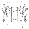
- Fig. 7a and Fig. 7b each show devices 9, wherein the in Fig. 7a shown device 9 on the left side of the drawer 2 and in Fig. 7b shown device 9 'on the right side of the drawer 2 can be arranged.
- the spring tongue 16 is provided with a stiffening 21 (for example, with a stiffening rib), which limits the flexibility of the spring tongue 16.
- a stiffening 21 for example, with a stiffening rib
- the device 9 'in Fig. 7b has a carrier 30 which receives in the mounting position, the front end of the extendable rail 8.
- This carrier 30 protrudes in Fig. 7b close to the stop surface 20 zoom, so as to accommodate the extendable rail 8 on the right side largely stable in position.
- the spring tongue 16, no stiffener 21, making it softer than the spring tongue 16 according to Fig. 7b is formed and can thus enable the desired lateral clearance compensation.
- the carrier 30 left ( Fig. 7a ) has a greater relative distance to the stop surface 20, so as to compensate for a lateral clearance between the device 9 and the rail 8.
- the device 9 may also have a further tongue 29, which rests in the mounting position at the front end of the rail 8, wherein by the further tongue 29 in the latched position between the device 9 and the rail 8 any occurring longitudinal play of the device 9 in relation to Rail 8 is compensated.
- the tongue 29 is formed bendable in the longitudinal direction of the rail 8.
- the longitudinal extension of the handle member 11 extends in the mounting position approximately parallel to the longitudinal extent of the rail 8, wherein the free end of the handle member 11 and the free end of the body 14 are substantially at the same height. In this way, a compact construction of the device 9 and an easily accessible operation of the handle member 11 can be made possible.
- the device 9 is at least made in two parts, wherein an integrally formed first leg - consisting of the counter-holding part 15 and the base body 14 - with a one-piece second leg - consisting of the locking part 10 and the handle part 11 - via a Helical spring are biased.
- the helical spring also serves as a hinge, so that the arrangement of a bending joint 13 (FIG. Fig. 3a ) can be omitted.
- the present invention is not limited to the embodiment shown, but includes any technical equivalents that may fall within the scope of the following claims. Also, the location information chosen in the description, such as top, bottom, side, left, right, etc. related to the immediately described and illustrated figure and are mutatis mutandis to transfer to the new situation in a change in position.
Description
Die vorliegende Erfindung bezieht sich auf eine Vorrichtung zum lösbaren Kuppeln einer Schublade mit einer ausziehbaren Schiene einer Schubladenausziehführung, umfassend:
- einen Rastteil, der zum lösbaren Kuppeln der Schublade mit der Schiene der Schubladenausziehführung lösbar arretierbar ist,
- einen zur Handbetätigung ausgebildeten Griffteil, durch den der Rastteil relativ zur Schiene der Schubladenausziehführung lösbar ist,
- einen Gegenhalteteil, wobei die Schiene in Montagelage zwischen dem Gegenhalteteil und dem Rastteil aufgenommen ist,
- wobei der Rastteil durch händischen Druck auf den Griffteil in eine vom Gegenhalteteil weg weisende Richtung bewegbar ist.
- a locking part, which is detachably lockable for releasably coupling the drawer to the rail of the drawer extension guide,
- a handle part designed for manual actuation, by means of which the latching part is releasable relative to the rail of the drawer pull-out guide,
- a counter-holding part, wherein the rail is received in the mounting position between the counter-holding part and the latching part,
- wherein the locking part is movable by manual pressure on the handle part in a direction away from the counter-holding part direction.
Im Weiteren betrifft die Erfindung eine Schubladenausziehführung mit einer Vorrichtung der zu beschreibenden Art sowie eine Schublade, welche über eine solche Vorrichtung mit einer ausziehbaren Schiene einer Schubladenausziehführung zu verbinden ist.Furthermore, the invention relates to a drawer extension with a device of the type to be described and a drawer, which is to be connected via such a device with an extendable rail a drawer extension.
Gemäß dem Stand der Technik sind Kupplungsvorrichtungen bekannt, durch die eine Schublade in ihrer Gesamtheit an einer ausziehbaren Schiene einer Schubladenausziehführung montierbar bzw. demontierbar ist, sodass die Schublade - beispielsweise zu Reinigungszwecken - vollständig von der Schubladenausziehführung gelöst und im Anschluss daran wieder befestigt werden kann. Die Kupplung der Schublade mit der Ausziehschiene kann automatisch erfolgen, indem ein federnder Rastteil der Vorrichtung mit einer vorgegebenen Verbindungsstelle der Ausziehschiene verrastet. Bei der Montage wird zunächst die Schubladenausziehführung am Möbel vormontiert, woraufhin die zu befestigende Schublade auf die in der Schließstellung befindliche Ausziehschiene aufgeschoben wird, bis über den Rastteil eine selbsttätige Verrastung der Schublade mit der Ausziehschiene erfolgt. Die Demontage der Schublade relativ zur Ausziehschiene kann ebenfalls werkzeuglos erfolgen, indem ein zur Handbetätigung ausgebildeter Griffteil betätigt wird, wodurch der Rastteil aus der Verrastung gelöst wird und die Schublade sodann entfernt werden kann.According to the prior art, coupling devices are known, by means of which a drawer in its entirety can be mounted or dismounted on an extendable rail of a drawer extension guide, so that the drawer can be completely detached from the drawer extension guide, for example for cleaning purposes, and then re-attached. The coupling of the drawer with the pull-out can be done automatically by a resilient locking part of the device locked with a predetermined connection point of the pull-out rail. During assembly, the drawer extension guide is first preassembled on the furniture, whereupon the drawer to be fastened is pushed onto the pull-out rail located in the closed position, until the drawer is automatically latched to the pull-out rail via the latching part. The disassembly of the drawer relative to the pull-out can also be done without tools by a designed for manual operation grip part is actuated, whereby the locking part is released from the latch and the drawer can then be removed.
Solche Kupplungsvorrichtungen für Schubladen sind in der
In der
In der
Bei der Verrastung zwischen der Schublade und der Ausziehschiene ist es günstig, wenn die Ausziehschiene bei der Montage des Schubkastens eine mehr oder weniger vorgegebene Position zum Rastteil einnimmt, sodass der Rastteil bestimmungsgemäß mit der vorgegebenen Verbindungsstelle der ausziehbaren Schiene verrasten kann. Wenn diese Lage nicht innerhalb eines vorgegebenen Toleranzbereiches liegt, so wäre es möglich, dass aus Kunststoff gespritzte Teile der Kupplungsvorrichtung durch das Aufschieben der Schublade auf die Ausziehschiene beschädigt oder von dieser sogar ganz abgeschert werden können.When locking between the drawer and the pull-out, it is advantageous if the pull-out during installation of the drawer occupies a more or less predetermined position to the locking part, so that the locking part can lock as intended with the predetermined connection point of the extendable rail. If this position is not within a predetermined tolerance range, it would be possible for parts of the coupling device injection molded from plastic to be damaged by the sliding of the drawer onto the pull-out rail or even to be sheared off completely therefrom.
Eine Vorrichtung gemäß dem Oberbegriff des Anspruchs 1 ist aus
Dies wir erfindungsgemäß durch die Merkmale des Patentanspruchs 1 gelöst. Weitere vorteilhafte Ausgestaltungen der Erfindung sind in den abhängigen Unteransprüchen angegeben.This we according to the invention by the features of claim 1. Further advantageous embodiments of the invention are specified in the dependent subclaims.
Gemäß der Erfindung ist also vorgesehen, dass der Gegenhalteteil wenigstens eine Federzunge aufweist.According to the invention it is thus provided that the counter-holding part has at least one spring tongue.
Durch diese Federzunge ist es möglich, dass die Schublade bei der Montage relativ zur ausziehbaren Schiene der Schubladenausziehführung in einer quer zur Ausziehrichtung verlaufenden Richtung - insbesondere seitlich - geführt wird, sodass also die Schublade bei der Montage durch die durch die Federzunge relativ zur Ausziehschiene zentriert wird und ein damit ein - insbesondere seitlicher - Spielausgleich der Schublade relativ zur ausziehbaren Schiene herbeigeführt wird.By this spring tongue, it is possible that the drawer during assembly relative to the pull-out rail of the drawer pull-out in a direction transverse to the extension direction - is guided, in particular laterally - so that so the drawer is centered during assembly by the spring tongue relative to the pull-out and thus a - in particular lateral - clearance compensation of the drawer is brought about relative to the pull-out rail.
Bei einem möglichen Ausführungsbeispiel kann vorgesehen sein, dass die Federzunge gemeinsam mit dem gegenüberliegenden Rastteil einen Einführtrichter für das vordere Ende der Ausziehschiene ausbilden, wobei die Breite des Einführtrichters in Montagelage in Richtung Schubladenfrontblende abnimmt.In one possible embodiment, it may be provided that the spring tongue form, together with the opposite latching part, an insertion funnel for the front end of the pull-out rail, wherein the width of the insertion funnel decreases in the mounting position in the direction of the drawer front panel.
Die Federzunge kann eine, vorzugsweise gekrümmte, Einlaufschräge aufweisen, durch welche die ausziehbare Schiene beim Einschieben in die Vorrichtung gegen den Rastteil drückbar ist. Es kann auch vorgesehen sein, dass die Federzunge und/oder der Rastteil in einer zur Längsrichtung der Schiene quer verlaufenden Richtung federnd ausgebildet ist bzw. sind, sodass allfällig auftretende Lagetoleranzen der Schublade relativ zur ausziehbaren Schiene kompensierbar sind. Je nach Einbaulage der Vorrichtung kann die Federzunge und/oder der Rastteil in horizontaler oder auch in vertikaler Richtung federnd ausgebildet sein.The spring tongue may have a, preferably curved, inlet bevel through which the extendable rail can be pressed against the latching part when it is pushed into the device. It can also be provided that the spring tongue and / or the locking part is designed to be resilient in a direction transverse to the longitudinal direction of the rail or are so that any occurring position tolerances of the drawer relative to the extendable rail can be compensated. Depending on the installation position of the device, the spring tongue and / or the locking part may be resilient in the horizontal or in the vertical direction.
Die erfindungsgemäße Schubladenausziehführung weist eine an einem Möbelkorpus zu befestigende Korpusschiene, wenigstens eine relativ zur Korpusschiene verschiebbar gelagerte Ausziehschiene sowie eine Vorrichtung der in Rede stehenden Art auf, durch welche eine Schublade lösbar mit der Ausziehschiene der Schubladenausziehführung zu verbinden ist.The drawer extension according to the invention has a to be fastened to a furniture body carcass rail, at least one displaceable relative to the carcass rail mounted pull-out rail and a device of the type in question through which a drawer is releasably connected to the pull-out of Schubladenausziehführung.
Bei einer konstruktiv einfachen Lösung kann vorgesehen sein, wenn der Rastteil und der Griffteil einstückig ausgebildet sind. Besonders günstig ist es, wenn die Vorrichtung in ihrer Gesamtheit einstückig aus Kunststoff hergestellt ist. Eine solche Vorrichtung kann also in einfacher Weise im Zuge eines Spritzgießverfahrens integral aus einem thermoplastischen Kunststoffmaterial hergestellt werden.In a structurally simple solution can be provided when the locking part and the handle part are integrally formed. It is particularly advantageous if the device is made in one piece from plastic in its entirety. Such a device can thus be produced in a simple manner in the course of an injection molding process integrally from a thermoplastic material.
Die erfindungsgemäße Schublade ist durch wenigstens eine Schubladenausziehführung der vorstehend genannten Art gekennzeichnet.The drawer according to the invention is characterized by at least one drawer extension guide of the type mentioned above.
Weitere Einzelheiten und Vorteile der vorliegenden Erfindung werden anhand der nachfolgenden Figurenbeschreibung erläutert. Dabei zeigt bzw. zeigen:
- Fig. 1
- eine perspektivische Ansicht eines Möbels mit Schubladen, welche in ihrer Gesamtheit an einer Schubladenausziehführung montierbar und demontierbar sind,
- Fig. 2
- eine perspektivische Ansicht einer an der Schubladenausziehführung befestigten Schublade,
- Fig. 3a-3d
- ein mögliches Ausführungsbeispiel einer Kupplungsvorrichtung in verschiedenen Ansichten,
- Fig. 4
- eine perspektivische Darstellung einer Schublade, welche über eine Trägerschiene lösbar mit einer ausziehbaren Schiene der Schubladenausziehführung verbindbar ist,
- Fig. 5a, 5b
- eine perspektivische Ansicht der Trägerschiene von unten mit einer daran montierten Kupplungsvorrichtung sowie eine vergrößerte Detaildarstellung hierzu,
- Fig. 6a, 6b
- eine Draufsicht auf die Trägerschiene von unten mit einer damit gekuppelten Ausziehschiene sowie eine vergrößerte Detaildarstellung hierzu,
- Fig. 7a, 7b
- Darstellungen von zwei verschiedenen Kupplungsvorrichtungen, wobei eine Kupplungsvorrichtung auf einer ersten Seite der Schublade und eine zweite Kupplungsvorrichtung auf der anderen Seite der Schublade angeordnet werden kann (links/rechts).
- Fig. 1
- a perspective view of a cabinet with drawers, which are mounted and dismounted in its entirety on a drawer extension guide,
- Fig. 2
- a perspective view of a drawer attached to the drawer pull-out,
- Fig. 3a-3d
- A possible embodiment of a coupling device in different views,
- Fig. 4
- a perspective view of a drawer, which is detachably connectable via a carrier rail with an extendable rail of the drawer extension guide,
- Fig. 5a, 5b
- a perspective view of the support rail from below with a coupling device mounted thereon and an enlarged detail illustration of this,
- Fig. 6a, 6b
- a top view of the carrier rail from below with a pull-out rail coupled thereto and an enlarged detail illustration of this,
- Fig. 7a, 7b
- Representations of two different coupling devices, wherein a coupling device on a first side of the drawer and a second coupling device on the other side of the drawer can be arranged (left / right).
Die Längserstreckung des Griffteiles 11 verläuft in Montagelage annähernd parallel zur Längserstreckung der Schiene 8, wobei das freie Ende des Griffteiles 11 und das freie Ende des Grundkörpers 14 im Wesentlichen auf selber Höhe liegen. Auf diese Weise kann eine kompakte Konstruktion der Vorrichtung 9 und eine leicht zugängliche Betätigung des Griffteiles 11 ermöglicht werden. Bei einem möglichen Ausführungsbeispiel kann auch vorgesehen sein, dass die Vorrichtung 9 zumindest zweiteilig ausgeführt ist, wobei ein einstückig ausgebildeter erster Schenkel - bestehend aus dem Gegenhalteteil 15 und dem Grundkörper 14 - mit einem einstückigen zweiten Schenkel - bestehend aus dem Rastteil 10 und dem Griffteil 11 - über eine Schraubenfeder vorgespannt sind. Die Schraubenfeder dient dabei auch als Gelenk, sodass auf die Anordnung eines Biegegelenkes 13 (
Die vorliegende Erfindung beschränkt sich nicht auf das gezeigte Ausführungsbeispiel, sondern umfasst bzw. erstreckt sich auf alle technischen Äquivalente, die in die Reichweite der nachfolgenden Ansprüche fallen können. Auch sind die in der Beschreibung gewählten Lageangaben, wie z.B. oben, unten, seitlich, links, rechts usw. auf die unmittelbar beschriebene sowie dargestellte Figur bezogen und sind bei einer Lageänderung sinngemäß auf die neue Lage zu übertragen.The present invention is not limited to the embodiment shown, but includes any technical equivalents that may fall within the scope of the following claims. Also, the location information chosen in the description, such as top, bottom, side, left, right, etc. related to the immediately described and illustrated figure and are mutatis mutandis to transfer to the new situation in a change in position.
Claims (15)
- A device (9) for releasably coupling a drawer (2) to an extendable rail (8) of a drawer extension guide (3), comprising:- a latching portion (10) which can be releasably arrested for releasably coupling the drawer (2) to the extendable rail (8) of the drawer extension guide (3),- a hand-actuated handle portion (11) for releasing the latching portion (10) relative to the extendable rail (8) of the drawer extension guide (3),- a counterpart holding portion (15), wherein the rail (8), in the mounted position, is accommodated between the counterpart holding portion (15) and the latching portion (10),- wherein the latching portion (10) is movable in a direction facing away from the counterpart holding portion (15) by hand pressure applied on the handle portion (11),
characterized in that the counterpart holding portion (15) has at least one spring tongue (16). - The device according to claim 1, characterized in that the spring tongue (16) has a, preferably curved, run-in incline for pressing the rail (8) against the latching portion (10) upon insertion of the rail into the device (9).
- The device according to claim 1 or 2, characterized in that the spring tongue (16) and the latching portion (10) are resilient in a direction extending transversely relative to the longitudinal direction of the rail (8).
- The device according to one of the claims 1 to 3, characterized in that the spring tongue (16) has a stiffening member (21).
- The device according to one of the claims 1 to 4, characterized in that a free end of the handle portion (11) is located at an end of the device (9) opposite to the latching portion (10).
- The device according to one of the claims 1 to 5, characterized in that the latching portion (10) has a catch portion (19) by which the device (9) can be releasably arrested relative to the rail (8) in a first depth position.
- The device according to claim 6, characterized in that the latching portion (10) has at least one abutment surface (20) for releasably arresting the device (9) in a second depth position differing from the first depth position.
- The device according to claim 7, characterized in that the catch portion (19) in the first depth position and the abutment surface (20) in the second depth position respectively engage into one and the same opening in the extendable rail (8).
- The device according to one of the claims 1 to 8, characterized in that the device (9) has a further tongue (29) which, in the mounted position, bears against the front end of the rail (8) so as to compensate for any longitudinal play between the device (1) and the rail (8) in the latched position between the device (9) and the rail (8).
- The device according to one of the claims 1 to 9, characterized in that the device (9) has at least one injection-molded fixing dowel (18) to fix the device (9) to a carrier rail (22) to be mounted to the drawer (2).
- The device according to one of the claims 1 to 10, characterized in that the device (9) is formed of plastic material and has a one-piece construction.
- A drawer extension guide (3) comprising a carcass rail (4) to be fixed to a furniture carcass (7), at least one rail (8) which is extendable relative to the carcass rail (4), and a device (9) according to one of the claims 1 to 11, by which a drawer (2) is to be releasably connected to the extendable rail (8).
- A drawer (2) comprising at least one drawer extension guide (3) according to claim 12.
- The drawer according to claim 13, characterized in that a carrier rail (22) is premounted to the drawer (2), wherein the carrier rail (22) can be releasably coupled by the device (9) relative to the extendable rail (8).
- The drawer according to claim 13 or 14, characterized in that a first device (9') is arranged at one side of the drawer (2) and a second device (9) is arranged on the other side of the drawer (2), wherein the spring tongue (16) of the first device (9'), preferably by providing a stiffening member (21), is configured to be stiffer than the spring tongue (16) of the second device (9).
Applications Claiming Priority (2)
| Application Number | Priority Date | Filing Date | Title |
|---|---|---|---|
| ATA1940/2010A AT510777B1 (en) | 2010-11-23 | 2010-11-23 | COUPLING DEVICE FOR DRAWERS |
| PCT/AT2011/000383 WO2012068594A1 (en) | 2010-11-23 | 2011-09-20 | Coupling device for drawers |
Publications (2)
| Publication Number | Publication Date |
|---|---|
| EP2642897A1 EP2642897A1 (en) | 2013-10-02 |
| EP2642897B1 true EP2642897B1 (en) | 2014-11-26 |
Family
ID=45044213
Family Applications (1)
| Application Number | Title | Priority Date | Filing Date |
|---|---|---|---|
| EP11788006.2A Active EP2642897B1 (en) | 2010-11-23 | 2011-09-20 | Coupling device for drawers |
Country Status (8)
| Country | Link |
|---|---|
| US (1) | US8696078B2 (en) |
| EP (1) | EP2642897B1 (en) |
| JP (1) | JP6006727B2 (en) |
| CN (1) | CN103220944B (en) |
| AT (1) | AT510777B1 (en) |
| ES (1) | ES2531213T3 (en) |
| MY (1) | MY164736A (en) |
| WO (1) | WO2012068594A1 (en) |
Families Citing this family (18)
| Publication number | Priority date | Publication date | Assignee | Title |
|---|---|---|---|---|
| US8979223B2 (en) * | 2012-12-12 | 2015-03-17 | Nan Juen International Co., Ltd. | Adjustable coupling device for connection between sliding rail assembly and a sliding box |
| US9101213B2 (en) * | 2013-11-22 | 2015-08-11 | Hardware Resources, Inc. | Undermount drawer slide position adjustment apparatus and method of use |
| US10149539B2 (en) | 2013-11-22 | 2018-12-11 | Hardware Resources, Inc. | Undermount drawer slide position adjustment apparatus and method of use |
| US9986829B2 (en) | 2013-11-22 | 2018-06-05 | Hardware Resources, Inc. | Undermount drawer slide position adjustment apparatus and method of use |
| TWM495781U (en) * | 2014-11-28 | 2015-02-21 | Sun Chain Trading Co Ltd | Front connection device of concealed sliding rail |
| DE102015101006A1 (en) * | 2015-01-23 | 2016-07-28 | Paul Hettich Gmbh & Co. Kg | Pull-out guide, set of two pull-out guides, furniture and motor vehicle with at least one storage device |
| DE202015001489U1 (en) * | 2015-02-25 | 2016-05-30 | Grass Gmbh | Device for the detachable connection of a furniture drawer movably guided in a furniture body via a guide unit with the guide unit |
| US10240632B2 (en) * | 2015-08-06 | 2019-03-26 | Handy Button Machine Co. | Drawer guide system |
| DE202015006943U1 (en) * | 2015-10-05 | 2017-01-09 | Grass Gmbh | Device for releasably connecting a movable in a furniture body of a furniture part via a guide unit furniture drawer with the guide unit |
| TWI548370B (en) * | 2015-11-12 | 2016-09-11 | 川湖科技股份有限公司 | Quick release mechanism for drawer slide parts |
| US20170174140A1 (en) * | 2015-12-17 | 2017-06-22 | Ford Global Technologies, Llc | Drawer assembly with anti-squeak and rattle system |
| USD858263S1 (en) * | 2016-06-16 | 2019-09-03 | Martas Precision Slide Co., Ltd. | Connector |
| USD884463S1 (en) * | 2016-06-16 | 2020-05-19 | Martas Precision Slide Co., Ltd. | Connector |
| DE102017128749A1 (en) * | 2017-12-04 | 2019-06-06 | Grass Gmbh | Device for connecting a push element to a guide rail, guide system and furniture or household appliance |
| CN109770584B (en) * | 2018-12-29 | 2023-12-01 | 广东库博精密科技有限公司 | Electric drawer easy to disassemble and assemble |
| DE102019204697B4 (en) * | 2019-04-02 | 2021-01-21 | Volkswagen Aktiengesellschaft | Device for holding a display and control device |
| DE102019113107A1 (en) | 2019-05-17 | 2020-11-19 | Paul Hettich Gmbh & Co. Kg | Drawer and method of assembling a drawer |
| DE102019113108A1 (en) * | 2019-05-17 | 2020-11-19 | Paul Hettich Gmbh & Co. Kg | Device for fixing a drawer |
Family Cites Families (23)
| Publication number | Priority date | Publication date | Assignee | Title |
|---|---|---|---|---|
| AT393203B (en) * | 1987-12-07 | 1991-09-10 | Alfit Gmbh | DRAWER WITH EXTENSION SET |
| DE8903741U1 (en) * | 1989-03-25 | 1989-05-03 | Paul Hettich Gmbh & Co, 4983 Kirchlengern, De | |
| US5281021A (en) | 1989-10-06 | 1994-01-25 | Julius Blum Gesellschaft M.B.H. | Arrangement for removably mounting a drawer to pull-out rails of drawer guide assemblies |
| DE4103045C1 (en) * | 1991-02-01 | 1992-08-20 | Ninkaplast Gmbh, 4902 Bad Salzuflen, De | Extension rail faster on drawer side wall - has hook, bolt, and bolt release as integral fastener unit, fitted into wall strip aperture |
| DE9215250U1 (en) * | 1992-11-10 | 1993-02-25 | Grass Ag, Hoechst, Vorarlberg, At | |
| DE9310582U1 (en) * | 1993-07-15 | 1993-09-23 | Hettich Paul Gmbh & Co | LOCKING DEVICE FOR DRAWERS OR THE LIKE |
| DE4432820B4 (en) * | 1994-09-15 | 2007-03-22 | MEPLA-WERKE LAUTENSCHLäGER GMBH & CO. KG | Fitting for height adjustment of drawers |
| AT404219B (en) * | 1995-01-19 | 1998-09-25 | Blum Gmbh Julius | DRAWER |
| DE20107278U1 (en) * | 2001-04-27 | 2001-08-02 | Hettich Paul Gmbh & Co | Device for producing a snap connection |
| CN1176625C (en) * | 2002-01-15 | 2004-11-24 | 南俊国际股份有限公司 | Slide-drawer connecting assembly and drawer opening and closing unit with the assembly |
| DE20217545U1 (en) * | 2002-11-13 | 2003-01-23 | Salice Arturo Spa | hinge |
| CN100534355C (en) * | 2003-05-13 | 2009-09-02 | 格拉斯有限公司 | Front locking device for releasably engaging a drawer to a drawer slide |
| US6945618B2 (en) * | 2003-06-02 | 2005-09-20 | Accuride International Inc. | Drawer slide adjustment mechanism |
| DE202004015100U1 (en) * | 2004-09-29 | 2006-02-09 | Alfit Ag | Fastening arrangement for the detachable fastening of pull-out guides to drawers |
| JP4623718B2 (en) * | 2004-12-17 | 2011-02-02 | 株式会社マッキンリー | Slide rail attachment / detachment device |
| DE202005005489U1 (en) * | 2005-04-07 | 2005-06-09 | Paul Hettich Gmbh & Co. Kg | Telescopic guide for furniture part, e.g. drawer, movably arranged in furniture body has insertion limiter on leading end region of running rail that contacts guide rail or central rail end when running rail has not yet been fully inserted |
| DE202005018788U1 (en) | 2005-12-01 | 2007-04-12 | Hettich Paul Gmbh & Co Kg | Telescopic guide for a furniture part displaceably arranged in a furniture carcass |
| DE202007001782U1 (en) * | 2006-09-08 | 2008-01-10 | Paul Hettich Gmbh & Co. Kg | drawer |
| CN101305867B (en) * | 2007-05-18 | 2011-09-21 | 川湖科技股份有限公司 | Fixture unit of drawer sliding rail |
| TW200944157A (en) * | 2008-04-18 | 2009-11-01 | King Slide Works Co Ltd | Positioning device for a drawer with a drawer slide |
| AT506879B1 (en) | 2008-06-10 | 2011-07-15 | Blum Gmbh Julius | DEVICE FOR RELEASABLE DUPLICATION OF A DRAWER WITH A RAIL OF A DRAWER EXTRACTOR |
| CN101711627B (en) * | 2008-10-08 | 2011-09-21 | 世塑有限公司 | Up-pressing detachment and combination structure |
| DE202009013706U1 (en) * | 2009-11-10 | 2011-03-31 | Paul Hettich Gmbh & Co. Kg | Device for coupling a drawer with a running rail of a pullout guide |
-
2010
- 2010-11-23 AT ATA1940/2010A patent/AT510777B1/en not_active IP Right Cessation
-
2011
- 2011-09-20 ES ES11788006T patent/ES2531213T3/en active Active
- 2011-09-20 JP JP2013539084A patent/JP6006727B2/en active Active
- 2011-09-20 MY MYPI2013001794A patent/MY164736A/en unknown
- 2011-09-20 CN CN201180056163.6A patent/CN103220944B/en active Active
- 2011-09-20 EP EP11788006.2A patent/EP2642897B1/en active Active
- 2011-09-20 WO PCT/AT2011/000383 patent/WO2012068594A1/en active Application Filing
-
2013
- 2013-05-22 US US13/899,931 patent/US8696078B2/en active Active
Also Published As
| Publication number | Publication date |
|---|---|
| US20130249366A1 (en) | 2013-09-26 |
| WO2012068594A1 (en) | 2012-05-31 |
| US8696078B2 (en) | 2014-04-15 |
| JP6006727B2 (en) | 2016-10-12 |
| ES2531213T3 (en) | 2015-03-12 |
| CN103220944B (en) | 2015-03-11 |
| JP2014500073A (en) | 2014-01-09 |
| MY164736A (en) | 2018-01-30 |
| AT510777A1 (en) | 2012-06-15 |
| AT510777B1 (en) | 2014-06-15 |
| CN103220944A (en) | 2013-07-24 |
| EP2642897A1 (en) | 2013-10-02 |
Similar Documents
| Publication | Publication Date | Title |
|---|---|---|
| EP2642897B1 (en) | Coupling device for drawers | |
| AT511081B1 (en) | ARRANGEMENT WITH A DRAWER AND WITH A DRAWER EXTRACTOR | |
| AT506879B1 (en) | DEVICE FOR RELEASABLE DUPLICATION OF A DRAWER WITH A RAIL OF A DRAWER EXTRACTOR | |
| EP2587962B1 (en) | Cabinet having a pull-out part | |
| CH626521A5 (en) | ||
| EP2750550A1 (en) | Drawer | |
| WO2006106029A1 (en) | Telescopic guide for a furniture part that can be displaced in the body of a piece of furniture | |
| WO2014071425A1 (en) | Drawer pull‑out guide | |
| EP2916686B1 (en) | Sliding-guide element and tabletop-fastening system for fastening a tabletop in a displaceable manner | |
| EP1513429B1 (en) | Arrangement for connecting a drawer frame to the bottom of a drawer | |
| EP2642896B1 (en) | Container rail for a drawer container | |
| EP4082394A1 (en) | Drawer rail for drawer extension guide | |
| EP3368734B1 (en) | Guide assembly for sliding doors and cupboard unit | |
| EP0914051A2 (en) | Guide fittings for pulling out drawers | |
| EP3189749B1 (en) | Pull-out guide for a movable furniture part | |
| DE202009002035U1 (en) | pull-out guide | |
| DE3135222C2 (en) | ||
| EP1084659B1 (en) | Assembly unit | |
| DE102018108647A1 (en) | Pull-out guide and drawer series | |
| EP0639687B1 (en) | Slide | |
| EP1449460B1 (en) | Pull-out rail, in particular for kitchen furniture | |
| WO2022207260A1 (en) | Coupling element, locking system and piece of furniture | |
| WO2012065195A1 (en) | Carrier rail for a drawer base | |
| WO2012065197A1 (en) | Support rail for a drawer bottom |
Legal Events
| Date | Code | Title | Description |
|---|---|---|---|
| PUAI | Public reference made under article 153(3) epc to a published international application that has entered the european phase |
Free format text: ORIGINAL CODE: 0009012 |
|
| 17P | Request for examination filed |
Effective date: 20130412 |
|
| AK | Designated contracting states |
Kind code of ref document: A1 Designated state(s): AL AT BE BG CH CY CZ DE DK EE ES FI FR GB GR HR HU IE IS IT LI LT LU LV MC MK MT NL NO PL PT RO RS SE SI SK SM TR |
|
| DAX | Request for extension of the european patent (deleted) | ||
| GRAP | Despatch of communication of intention to grant a patent |
Free format text: ORIGINAL CODE: EPIDOSNIGR1 |
|
| INTG | Intention to grant announced |
Effective date: 20140805 |
|
| GRAS | Grant fee paid |
Free format text: ORIGINAL CODE: EPIDOSNIGR3 |
|
| GRAA | (expected) grant |
Free format text: ORIGINAL CODE: 0009210 |
|
| AK | Designated contracting states |
Kind code of ref document: B1 Designated state(s): AL AT BE BG CH CY CZ DE DK EE ES FI FR GB GR HR HU IE IS IT LI LT LU LV MC MK MT NL NO PL PT RO RS SE SI SK SM TR |
|
| REG | Reference to a national code |
Ref country code: GB Ref legal event code: FG4D Free format text: NOT ENGLISH |
|
| REG | Reference to a national code |
Ref country code: CH Ref legal event code: EP |
|
| REG | Reference to a national code |
Ref country code: AT Ref legal event code: REF Ref document number: 697677 Country of ref document: AT Kind code of ref document: T Effective date: 20141215 |
|
| REG | Reference to a national code |
Ref country code: IE Ref legal event code: FG4D Free format text: LANGUAGE OF EP DOCUMENT: GERMAN |
|
| REG | Reference to a national code |
Ref country code: DE Ref legal event code: R096 Ref document number: 502011005126 Country of ref document: DE Effective date: 20150108 |
|
| REG | Reference to a national code |
Ref country code: ES Ref legal event code: FG2A Ref document number: 2531213 Country of ref document: ES Kind code of ref document: T3 Effective date: 20150312 |
|
| REG | Reference to a national code |
Ref country code: NL Ref legal event code: VDEP Effective date: 20141126 |
|
| REG | Reference to a national code |
Ref country code: LT Ref legal event code: MG4D |
|
| PG25 | Lapsed in a contracting state [announced via postgrant information from national office to epo] |
Ref country code: IS Free format text: LAPSE BECAUSE OF FAILURE TO SUBMIT A TRANSLATION OF THE DESCRIPTION OR TO PAY THE FEE WITHIN THE PRESCRIBED TIME-LIMIT Effective date: 20150326 Ref country code: NL Free format text: LAPSE BECAUSE OF FAILURE TO SUBMIT A TRANSLATION OF THE DESCRIPTION OR TO PAY THE FEE WITHIN THE PRESCRIBED TIME-LIMIT Effective date: 20141126 Ref country code: LT Free format text: LAPSE BECAUSE OF FAILURE TO SUBMIT A TRANSLATION OF THE DESCRIPTION OR TO PAY THE FEE WITHIN THE PRESCRIBED TIME-LIMIT Effective date: 20141126 Ref country code: NO Free format text: LAPSE BECAUSE OF FAILURE TO SUBMIT A TRANSLATION OF THE DESCRIPTION OR TO PAY THE FEE WITHIN THE PRESCRIBED TIME-LIMIT Effective date: 20150226 Ref country code: FI Free format text: LAPSE BECAUSE OF FAILURE TO SUBMIT A TRANSLATION OF THE DESCRIPTION OR TO PAY THE FEE WITHIN THE PRESCRIBED TIME-LIMIT Effective date: 20141126 Ref country code: PT Free format text: LAPSE BECAUSE OF FAILURE TO SUBMIT A TRANSLATION OF THE DESCRIPTION OR TO PAY THE FEE WITHIN THE PRESCRIBED TIME-LIMIT Effective date: 20150326 |
|
| PG25 | Lapsed in a contracting state [announced via postgrant information from national office to epo] |
Ref country code: SE Free format text: LAPSE BECAUSE OF FAILURE TO SUBMIT A TRANSLATION OF THE DESCRIPTION OR TO PAY THE FEE WITHIN THE PRESCRIBED TIME-LIMIT Effective date: 20141126 Ref country code: CY Free format text: LAPSE BECAUSE OF FAILURE TO SUBMIT A TRANSLATION OF THE DESCRIPTION OR TO PAY THE FEE WITHIN THE PRESCRIBED TIME-LIMIT Effective date: 20141126 Ref country code: HR Free format text: LAPSE BECAUSE OF FAILURE TO SUBMIT A TRANSLATION OF THE DESCRIPTION OR TO PAY THE FEE WITHIN THE PRESCRIBED TIME-LIMIT Effective date: 20141126 Ref country code: GR Free format text: LAPSE BECAUSE OF FAILURE TO SUBMIT A TRANSLATION OF THE DESCRIPTION OR TO PAY THE FEE WITHIN THE PRESCRIBED TIME-LIMIT Effective date: 20150227 Ref country code: LV Free format text: LAPSE BECAUSE OF FAILURE TO SUBMIT A TRANSLATION OF THE DESCRIPTION OR TO PAY THE FEE WITHIN THE PRESCRIBED TIME-LIMIT Effective date: 20141126 Ref country code: RS Free format text: LAPSE BECAUSE OF FAILURE TO SUBMIT A TRANSLATION OF THE DESCRIPTION OR TO PAY THE FEE WITHIN THE PRESCRIBED TIME-LIMIT Effective date: 20141126 |
|
| PG25 | Lapsed in a contracting state [announced via postgrant information from national office to epo] |
Ref country code: CZ Free format text: LAPSE BECAUSE OF FAILURE TO SUBMIT A TRANSLATION OF THE DESCRIPTION OR TO PAY THE FEE WITHIN THE PRESCRIBED TIME-LIMIT Effective date: 20141126 Ref country code: EE Free format text: LAPSE BECAUSE OF FAILURE TO SUBMIT A TRANSLATION OF THE DESCRIPTION OR TO PAY THE FEE WITHIN THE PRESCRIBED TIME-LIMIT Effective date: 20141126 Ref country code: DK Free format text: LAPSE BECAUSE OF FAILURE TO SUBMIT A TRANSLATION OF THE DESCRIPTION OR TO PAY THE FEE WITHIN THE PRESCRIBED TIME-LIMIT Effective date: 20141126 Ref country code: RO Free format text: LAPSE BECAUSE OF FAILURE TO SUBMIT A TRANSLATION OF THE DESCRIPTION OR TO PAY THE FEE WITHIN THE PRESCRIBED TIME-LIMIT Effective date: 20141126 Ref country code: SK Free format text: LAPSE BECAUSE OF FAILURE TO SUBMIT A TRANSLATION OF THE DESCRIPTION OR TO PAY THE FEE WITHIN THE PRESCRIBED TIME-LIMIT Effective date: 20141126 |
|
| REG | Reference to a national code |
Ref country code: DE Ref legal event code: R097 Ref document number: 502011005126 Country of ref document: DE |
|
| PG25 | Lapsed in a contracting state [announced via postgrant information from national office to epo] |
Ref country code: PL Free format text: LAPSE BECAUSE OF FAILURE TO SUBMIT A TRANSLATION OF THE DESCRIPTION OR TO PAY THE FEE WITHIN THE PRESCRIBED TIME-LIMIT Effective date: 20141126 |
|
| PLBE | No opposition filed within time limit |
Free format text: ORIGINAL CODE: 0009261 |
|
| STAA | Information on the status of an ep patent application or granted ep patent |
Free format text: STATUS: NO OPPOSITION FILED WITHIN TIME LIMIT |
|
| 26N | No opposition filed |
Effective date: 20150827 |
|
| PG25 | Lapsed in a contracting state [announced via postgrant information from national office to epo] |
Ref country code: SI Free format text: LAPSE BECAUSE OF FAILURE TO SUBMIT A TRANSLATION OF THE DESCRIPTION OR TO PAY THE FEE WITHIN THE PRESCRIBED TIME-LIMIT Effective date: 20141126 |
|
| PG25 | Lapsed in a contracting state [announced via postgrant information from national office to epo] |
Ref country code: MC Free format text: LAPSE BECAUSE OF FAILURE TO SUBMIT A TRANSLATION OF THE DESCRIPTION OR TO PAY THE FEE WITHIN THE PRESCRIBED TIME-LIMIT Effective date: 20141126 Ref country code: LU Free format text: LAPSE BECAUSE OF FAILURE TO SUBMIT A TRANSLATION OF THE DESCRIPTION OR TO PAY THE FEE WITHIN THE PRESCRIBED TIME-LIMIT Effective date: 20150920 |
|
| REG | Reference to a national code |
Ref country code: CH Ref legal event code: PL |
|
| GBPC | Gb: european patent ceased through non-payment of renewal fee |
Effective date: 20150920 |
|
| REG | Reference to a national code |
Ref country code: IE Ref legal event code: MM4A |
|
| REG | Reference to a national code |
Ref country code: FR Ref legal event code: ST Effective date: 20160531 |
|
| PG25 | Lapsed in a contracting state [announced via postgrant information from national office to epo] |
Ref country code: IE Free format text: LAPSE BECAUSE OF NON-PAYMENT OF DUE FEES Effective date: 20150920 Ref country code: GB Free format text: LAPSE BECAUSE OF NON-PAYMENT OF DUE FEES Effective date: 20150920 Ref country code: LI Free format text: LAPSE BECAUSE OF NON-PAYMENT OF DUE FEES Effective date: 20150930 Ref country code: CH Free format text: LAPSE BECAUSE OF NON-PAYMENT OF DUE FEES Effective date: 20150930 |
|
| PG25 | Lapsed in a contracting state [announced via postgrant information from national office to epo] |
Ref country code: FR Free format text: LAPSE BECAUSE OF NON-PAYMENT OF DUE FEES Effective date: 20150930 |
|
| REG | Reference to a national code |
Ref country code: DE Ref legal event code: R079 Ref document number: 502011005126 Country of ref document: DE Free format text: PREVIOUS MAIN CLASS: A47B0088040000 Ipc: A47B0088400000 |
|
| PG25 | Lapsed in a contracting state [announced via postgrant information from national office to epo] |
Ref country code: MT Free format text: LAPSE BECAUSE OF FAILURE TO SUBMIT A TRANSLATION OF THE DESCRIPTION OR TO PAY THE FEE WITHIN THE PRESCRIBED TIME-LIMIT Effective date: 20141126 |
|
| PG25 | Lapsed in a contracting state [announced via postgrant information from national office to epo] |
Ref country code: SM Free format text: LAPSE BECAUSE OF FAILURE TO SUBMIT A TRANSLATION OF THE DESCRIPTION OR TO PAY THE FEE WITHIN THE PRESCRIBED TIME-LIMIT Effective date: 20141126 Ref country code: HU Free format text: LAPSE BECAUSE OF FAILURE TO SUBMIT A TRANSLATION OF THE DESCRIPTION OR TO PAY THE FEE WITHIN THE PRESCRIBED TIME-LIMIT; INVALID AB INITIO Effective date: 20110920 Ref country code: BG Free format text: LAPSE BECAUSE OF FAILURE TO SUBMIT A TRANSLATION OF THE DESCRIPTION OR TO PAY THE FEE WITHIN THE PRESCRIBED TIME-LIMIT Effective date: 20141126 |
|
| PG25 | Lapsed in a contracting state [announced via postgrant information from national office to epo] |
Ref country code: BE Free format text: LAPSE BECAUSE OF NON-PAYMENT OF DUE FEES Effective date: 20150930 |
|
| PG25 | Lapsed in a contracting state [announced via postgrant information from national office to epo] |
Ref country code: MK Free format text: LAPSE BECAUSE OF FAILURE TO SUBMIT A TRANSLATION OF THE DESCRIPTION OR TO PAY THE FEE WITHIN THE PRESCRIBED TIME-LIMIT Effective date: 20141126 |
|
| PG25 | Lapsed in a contracting state [announced via postgrant information from national office to epo] |
Ref country code: AL Free format text: LAPSE BECAUSE OF FAILURE TO SUBMIT A TRANSLATION OF THE DESCRIPTION OR TO PAY THE FEE WITHIN THE PRESCRIBED TIME-LIMIT Effective date: 20141126 |
|
| P01 | Opt-out of the competence of the unified patent court (upc) registered |
Effective date: 20230523 |
|
| PGFP | Annual fee paid to national office [announced via postgrant information from national office to epo] |
Ref country code: TR Payment date: 20230828 Year of fee payment: 13 Ref country code: IT Payment date: 20230920 Year of fee payment: 13 Ref country code: AT Payment date: 20230928 Year of fee payment: 13 |
|
| PGFP | Annual fee paid to national office [announced via postgrant information from national office to epo] |
Ref country code: DE Payment date: 20230928 Year of fee payment: 13 |
|
| PGFP | Annual fee paid to national office [announced via postgrant information from national office to epo] |
Ref country code: ES Payment date: 20231017 Year of fee payment: 13 |