EP3921607B1 - Gravimetrisches messsystem - Google Patents
Gravimetrisches messsystem Download PDFInfo
- Publication number
- EP3921607B1 EP3921607B1 EP20704453.8A EP20704453A EP3921607B1 EP 3921607 B1 EP3921607 B1 EP 3921607B1 EP 20704453 A EP20704453 A EP 20704453A EP 3921607 B1 EP3921607 B1 EP 3921607B1
- Authority
- EP
- European Patent Office
- Prior art keywords
- weighing
- module
- recesses
- weighing chamber
- chamber
- Prior art date
- Legal status (The legal status is an assumption and is not a legal conclusion. Google has not performed a legal analysis and makes no representation as to the accuracy of the status listed.)
- Active
Links
Images

Classifications
-
- G—PHYSICS
- G01—MEASURING; TESTING
- G01G—WEIGHING
- G01G21/00—Details of weighing apparatus
- G01G21/28—Frames, Housings
- G01G21/286—Frames, Housings with windshields
-
- H—ELECTRICITY
- H05—ELECTRIC TECHNIQUES NOT OTHERWISE PROVIDED FOR
- H05K—PRINTED CIRCUITS; CASINGS OR CONSTRUCTIONAL DETAILS OF ELECTRIC APPARATUS; MANUFACTURE OF ASSEMBLAGES OF ELECTRICAL COMPONENTS
- H05K5/00—Casings, cabinets or drawers for electric apparatus
- H05K5/02—Details
- H05K5/03—Covers
-
- H—ELECTRICITY
- H05—ELECTRIC TECHNIQUES NOT OTHERWISE PROVIDED FOR
- H05K—PRINTED CIRCUITS; CASINGS OR CONSTRUCTIONAL DETAILS OF ELECTRIC APPARATUS; MANUFACTURE OF ASSEMBLAGES OF ELECTRICAL COMPONENTS
- H05K7/00—Constructional details common to different types of electric apparatus
- H05K7/14—Mounting supporting structure in casing or on frame or rack
- H05K7/1422—Printed circuit boards receptacles, e.g. stacked structures, electronic circuit modules or box like frames
- H05K7/1424—Card cages
-
- H—ELECTRICITY
- H05—ELECTRIC TECHNIQUES NOT OTHERWISE PROVIDED FOR
- H05K—PRINTED CIRCUITS; CASINGS OR CONSTRUCTIONAL DETAILS OF ELECTRIC APPARATUS; MANUFACTURE OF ASSEMBLAGES OF ELECTRICAL COMPONENTS
- H05K7/00—Constructional details common to different types of electric apparatus
- H05K7/18—Construction of rack or frame
-
- G—PHYSICS
- G01—MEASURING; TESTING
- G01G—WEIGHING
- G01G23/00—Auxiliary devices for weighing apparatus
- G01G23/48—Temperature-compensating arrangements
Definitions
- An electromechanical weighing system ie a typically complex lever system with an input-side load pickup and an output-side plunger coil arrangement, is arranged in a weighing system space that is intended to ensure the best possible shielding from environmental influences.
- a carrier connected to the load receiver protrudes into a usually adjacent weighing space, which is also largely shielded from the environment, namely by its weighing space wall.
- the weighing chamber wall usually consists of the weighing chamber floor, the weighing chamber cover, weighing chamber side walls and a front and rear wall.
- the back wall can often coincide with a wall of the weighing system room.
- One or both side walls of the weighing compartment are often designed as movable windbreak elements.
- the cover and/or the front can also contain access openings, which can usually be closed.
- the coupling of the carrier for carrying the load of the weighing system usually passes through the rear wall or the floor of the weighing chamber.
- Such scales always contain a control device which, in particular, activates the weighing sensors and thereby specifically regulates the plunger coil arrangement of the weighing system.
- the control devices of modern scales can be designed to be significantly more complex and, in particular, can make different operating variants of the system operation available.
- Such operating variants can relate to the control of the sensors or a cooling device, but they can alternatively or additionally relate to the activation of certain auxiliary devices in or on the weighing room.
- a cooling device, a wind protection control, lifting devices within the weighing chamber, lighting devices and the like are mentioned purely by way of example.
- auxiliary devices with reference to the weighing function in the form of modules, i.e. as modules related to the weighing function, or function modules for short, and to provide a rail-like holding device in the weighing room, in particular on its rear wall, which has different mechanical interfaces which function modules required in the specific individual case can be specified in the required position.
- said function modules can be inserted into corresponding module receptacles on the weighing chamber wall as required.
- the Post-Released EP 3 557 199 A1 discloses a scale with a weighing chamber rear wall that can be assembled from several wall elements, the height of which can be adjusted in this way to different draft protection heights, and consequently weighing chambers of different heights can be built up.
- the EP 1 312 902 A1 discloses a scale, on the rear wall of the weighing chamber, an additional electronic unit, in which supply units, for example a battery, or else control electronics can be arranged, thus a functional module in the local sense, can be attached.
- U.S. 2010/0276213 A1 discloses a scale on whose weighing chamber rear wall control electronics are arranged. This is mechanically and electronically connected to a dosing nozzle located above the load receptor, so that the scale can be used as a dosing device.
- the EP 1 396 711 B1 discloses a scale with a weighing chamber that is not equipped with any functional modules, which has heat dissipation from the weighing electronics and from the weighing chamber mediated by a thermoelectric element, with the special thermal coupling to the rear wall of the weighing chamber ensuring the formation of a temperature gradient within the weighing chamber.
- the DE 10 2014 101 561 A1 discloses a gravimetric dosing device with a climate measuring module arranged in the weighing chamber. On the basis of the climate data determined in this way components to be mixed can be preheated outside of the device as part of the dosing process.
- the at least one weighing chamber wall is designed as a support structure made up of posts and struts, for example, which free spaces occupying the majority of the wall surface represent said Has recesses forming module receptacles, the recesses being optionally closable by said, spatially adapted to them, non-weighing screens or said functional modules.
- Preferred embodiments are subject of the dependent claims.
- the invention envisages constructing at least one weighing chamber wall, preferably several weighing chamber walls, as a skeleton or lattice structure which offers several recesses of the same design for the insertion of different functional modules. Because the module receptacles are designed in the same way, function modules that are designed in the same way but have different effects can be installed at virtually any point on the weighing chamber wall, particularly where they are needed according to current needs.
- the design of the module receptacles as recesses also allows additional connections, which will be discussed further below, to be positioned outside of the weighing chamber, so that only the components that are absolutely necessary there are located in the weighing chamber itself. This is of great importance in terms of safety, cleanliness, temperature management, etc.
- the aim of the invention is to offer particular flexibility when packaging a scale, more module receptacles are preferably provided than functional modules have to be installed in typical applications.
- the invention provides that the gravimetric measuring system also has, in addition to the scale and the functional modules, panels without a weighing function, with which those module receptacles can be closed in which no functional module is currently installed. In this way, different scales can be assembled for different applications, which, however, all have a weighing chamber with equipment reduced to the minimum required for the desired function.
- the module receptacles according to the invention preferably not only provide a purely mechanical fixing interface. Rather, further interfaces are made available, particularly with regard to active function modules.
- the invention provides that the support structure has a device-side identification interface component in the area of at least one of its recesses, which is contacted by a corresponding, module-side identification interface component to transmit identification data when a functional module is inserted.
- the device-side identification interface components can be embodied as optical, magnetic, tactile, radio or electronic receiving units and the module-side identification interface components can be embodied as corresponding optical, magnetic, tactile, radio or electronic transmitter units.
- the background to these measures is the creation of a possibility of automatic detection and identification of the respectively installed function modules. In particular, an automatic detection of the module constellation can be provided by the control unit of the scale. This information can then be used to adjust the functional controls of the scale.
- the support structure in The area of at least one of its recesses has a device-side thermal interface component that is thermally connected to a central cooling device and that is thermally contacted by a corresponding module-side thermal interface component when a (particularly active) functional module is inserted.
- a device-side thermal interface component that is thermally connected to a central cooling device and that is thermally contacted by a corresponding module-side thermal interface component when a (particularly active) functional module is inserted.
- Such thermal interfaces allow the targeted dissipation of heat generated in active function modules by their electrical and electronic components. Motorized units, lighting units, ionizers, etc. are given here purely by way of example.
- control device can activate special operating variants of the cooling device depending on the detected module constellation, so that despite the differences in the amount and distribution of the heat output with different module constellations, an exact cooling compensation is nevertheless implemented. This means that a constant, optimized temperature distribution in the weighing chamber can be achieved.
- module receptacles should also have corresponding interface components for electrical and electronic, in particular data-related contacting of the active functional modules, which are then preferably automatically contacted by corresponding module-side interface components when the functional modules are installed.
- the wall of the weighing room where there is the greatest need for the installation of function modules is usually the partition wall to the weighing system room, i.e. to the room in which the mechatronic weighing system is located, e.g. a strain gauge (strain gauge) or EMF (electromagnetic compensation) system , located.
- This weighing system room must be completely sealed, ie inaccessible to the user of the scale, so that the corresponding scale can meet the legal calibration requirements. This appears to be in conflict with the accessibility of all interfaces explained above.
- a development of the invention therefore provides that if the weighing chamber wall designed as said support structure is positioned as a separating element between the weighing chamber and a weighing system chamber, which encloses the weighing system connected to a weighing goods carrier arranged in the weighing chamber, the Recesses in the support structure on the weighing system room side through a permanently installed end wall are locked.
- the weighing chamber wall in question is constructed in two layers.
- the recesses according to the invention are open toward the weighing chamber and have the device-side interface components that are accessible from the weighing chamber.
- FIG 1 shows a schematic representation of a gravimetric measuring system 10 according to the invention, which consists essentially of a scale 12 and two functional modules 14, 16 used therein and a diaphragm 15.
- the functional module provided with reference number 14 is a laser scanner unit suitable for recognizing bar codes and the functional module provided with reference number 16 is a lighting unit.
- the specific functions of the function modules 14, 16 play no role in the context of the present invention.
- the scale 12 essentially comprises three areas, namely a weighing system space 18, in which an in figure 3 indicated weighing system 181 is arranged.
- the specific structure of the weighing system 181 is irrelevant in the context of the present invention.
- the weighing system 181 comprises a load receiver, not shown separately, which is connected to a carrier 20 for the weighing item, which in turn is arranged in a weighing space 22 adjoining the weighing system space 18 in the illustrated embodiment.
- the weighing chamber 22 is surrounded by a weighing chamber wall which figure 1 is only partially shown.
- the weighing chamber rear wall 28 is in the representation of figure 1 essentially covered by the front sides of the functional modules 14, 16 and the panel 15 arranged between these functional modules 14, 16.
- the weighing chamber wall also includes another weighing chamber side wall, a weighing chamber front wall and a (only in the Figures 2 and 3 indicated) weighing chamber cover 23, which for reasons of clarity in figure 1 however, are not shown.
- the scale 12 includes an electronics unit 30 which, in the embodiment shown, essentially includes a large-format display.
- the electronic unit 30 can additionally contain a control device, which is referred to further below will have to be dealt with in more detail.
- this control device can also be arranged at a different point on the scale 12 . It is considered favorable if this control unit is thermally insulated from the weighing system space 18 and from the weighing space 22 .
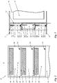
- figure 2 shows a front view of the weighing chamber rear wall 28, but without the function modules 14, 16 used and without the panel 15.
- figure 3 shows a sectional view of the weighing chamber rear wall 28 and adjacent areas of the scale 12, the representation of figure 3 however, the function modules 14, 16 used and the panel 15 used also show. Despite this difference, a synopsis of the Figures 2 and 3 understanding of the following description.
- the rear wall 28 of the weighing chamber is made up of vertical posts 281 and struts 282 arranged transversely thereto. Recesses 283, which are also referred to here as module receptacles 283, extend between these.
- the weighing compartment rear wall 28 On the weighing system compartment side, the weighing compartment rear wall 28 has an end wall 284 that seals the weighing system compartment 18 and prevents the module receptacles 283 from reaching into the weighing system compartment 18 .
- the end wall 284 is also the front wall of the weighing system compartment 18.
- the module recordings 283 are used for the spatially adapted recording of the function modules 14, 16 Figures 2 and 3 middle module receptacle 283 is in the embodiment of figures 1 and 3 no function module used. This recess 283 between the post 281 and struts 282 is closed by the screen 15 to the weighing chamber.
- the module mounts 283 are of identical design with regard to their equipment, which is to be described in more detail below, so that the function modules 14, 16 can be inserted into each of the module mounts 283, just like other functional modules of compatible design.
- the module receptacles 283 are preferably identical, particularly preferably designed to merge into one another without a separating element, so that functional modules 14, 16, the size of which corresponds to an integer multiple of a standard size, can be inserted exactly into one or more adjacent module receptacles 283.
- module receptacles 283 themselves are different integer multiples of a standard size.
- function modules 14, 16 also applies to the panels 15.
- Each module receptacle 283 has a device-side identification interface component 30a, which can interact with a corresponding, module-side identification interface component 30b of a functional module 14, 16 used, in order to identify the functional module 14, 16 used and via a corresponding data line (dashed lines). connect to a control unit.
- each module receptacle 283 has a device-side thermal interface component 32a, which is in thermal contact with a corresponding, module-side thermal interface component 32b of an inserted functional module 14, 16.
- the device-side thermal interface components 32b are thermally connected to one another and to a cooling device (not shown) (dotted lines).
- module-side thermal interface components 32b of the embodiment shown have different contact surface sizes compared to the device-side thermal interface components 32a and among one another. All module-side thermal interface components 32b are smaller than or at most the same size as the device-side thermal interface components 32a of the same size.
- the specific size of the module-side contact surfaces depends on the heat output of the respective functional modules 14, 16. In particular, there can be a proportionality between the heat output and the size of the thermal contact area of the modules.
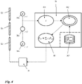
- FIG 4 shows a preferred embodiment of a controller for the scales 12.
- the thermal ones are shown below one another and with a cooling device 34 connected device-side thermal interface components 32a and device-side identification interface components 30a, which are each identified here with the index i.
- the identification data obtained through the interaction of the device-side and module-side identification interface components 30a, b are sent to a control device 36, there in particular to the identification unit 361.
- the identification can be module-type-specific or even module-specific.
- the identification data are sent from the identification unit 361 to a central unit 362 .
- the storage unit 363 can be integrated into the control device 36 or kept remote from it, for example in a server connected via the Internet.
- this information can also be stored in a memory unit of the functional module itself.
- a type-specific deposit without individual measurement is also possible.
- storing information in the module itself combines the advantages of relieving the load on the scales control unit, independence from external data sources and the possibility of individualisation.
- the central unit 362 calculates the default values for controlling the cooling device 34, which are forwarded to a cooling control unit 364 connected to the cooling device.
- the weighting factor c i can be used, for example, to take into account the special position, ie the special module receptacle, in which a function module 14, 16 is inserted. Such a weighting can of course also be dispensed with, ie the weighting factor then corresponds to 1 or is identical in all summands.
- This static cooling power P st is distributed equally by the cooling device 34 to all of the device-side thermal interface components 32a.
- the needs-based distribution to the functional modules 14, 16 takes place via the different sizes of the module-side thermal interface components 32b.
- the correction cooling power P v is also provided, with which small fluctuations in the temperature T in the weighing chamber 22 can be compensated.
Landscapes
- Physics & Mathematics (AREA)
- General Physics & Mathematics (AREA)
- Engineering & Computer Science (AREA)
- Microelectronics & Electronic Packaging (AREA)
- Cooling Or The Like Of Electrical Apparatus (AREA)
- Weight Measurement For Supplying Or Discharging Of Specified Amounts Of Material (AREA)
- Investigating Or Analyzing Materials Using Thermal Means (AREA)
- Arrangements For Transmission Of Measured Signals (AREA)
- Control Of Temperature (AREA)
Description
- Die Erfindung bezieht sich auf ein gravimetrisches Messsystem, umfassend
- eine Waage mit einem von einer Wägeraumwandung umgebenen Wägeraum, einem elektromechanischen Wägesystem und einer elektronischen Steuereinrichtung zur Steuerung des Systembetriebs gemäß in ihrem Speicher hinterlegten Regeln sowie
- eine Mehrzahl von Funktionsmodulen, die bedarfsweise in an der Wägeraumwandung angeordnete Modulaufnahmen einsetzbar sind.
- Derartige gravimetrische Messsysteme sind bekannt aus der
EP 1 195 584 A1 . - Analyse- und Laborwaagen, insbesondere solche, die auf dem Prinzip der elektromagnetischen Kompensation arbeiten, sind allgemein bekannt. Ein elektromechanisches Wägesystem, d. h. ein typischerweise komplexes Hebelwerk mit einer eingangsseitigen Lastaufnahme und einer ausgangsseitigen Tauchspulenanordnung, ist dabei in einem Wägesystemraum angeordnet, der eine möglichst gute Abschirmung gegenüber Umgebungseinflüssen gewähren soll. Ein mit der Lastaufnahme verbundener Träger ragt in einen üblicherweise benachbarten Wägeraum hinein, der ebenfalls, nämlich durch seine Wägeraumwandung, weitgehend von der Umgebung abgeschirmt ist. Die Wägeraumwandung setzt sich üblicherweise aus dem Wägeraumboden, den Wägeraumdeckel, Wägeraumseitenwänden sowie eine Vorder- und Rückwand zusammen. Die Rückwand kann häufig mit einer Wand des Wägesystemraums zusammenfallen. Eine oder beide Seitenwände des Wägeraums sind häufig als bewegbare Windschutz-Elemente ausgebildet. Auch der Deckel und/oder die Vorderseite können, in der Regel verschließbare, Zugangsöffnungen enthalten. Die Kopplung des Trägers zur Lastaufnahme des Wägesystems durchsetzt üblicherweise die Rückwand oder den Boden des Wägeraums.
- Weiter enthalten derartige Waagen stets eine Steuereinrichtung, die insbesondere die Wägesensorik ansteuert und dabei speziell die Tauchspulenanordnung des Wägesystems regelt. Allerdings können die Steuereinrichtungen moderner Waagen deutlich komplexer ausgestaltet sein und insbesondere verschiedene Betriebsvarianten des Systembetriebs zur Verfügung stellen. Solche Betriebsvarianten können die Steuerung der Sensorik oder einer Kühlvorrichtung betreffen, sie können sich jedoch alternativ oder zusätzlich auf die Ansteuerung bestimmter Hilfseinrichtungen im oder am Wägeraum beziehen. Rein beispielhaft seien eine Kühlvorrichtung, eine Windschutzsteuerung, Hebevorrichtungen innerhalb des Wägeraums, Beleuchtungseinrichtungen und ähnliches genannt.
- Aus der eingangs genannten, gattungsbildenden Druckschrift ist es bekannt, solche Hilfseinrichtungen mit Wägefunktionsbezug in Form von Modulen, d. h. als wägefunktionsbezogene Module, kurz Funktionsmodule, vorzuhalten und im Wägeraum, insbesondere an dessen Rückwand, eine schienenartige Haltevorrichtung vorzusehen, welche unterschiedliche mechanische Schnittstellen aufweist, an welchen im konkreten Einzelfall benötigte Funktionsmodule in der jeweils benötigten Position festgelegt werden können. Mit anderen Worten sind besagte Funktionsmodule bedarfsweise in entsprechende Modulaufnahmen an der Wägeraumwandung einsetzbar. Ein solch modulares System ist insbesondere in Laborumgebungen vorteilhaft, in denen mit ein und derselben Waage unterschiedliche Wägeaufgaben durchgeführt werden müssen. Die Waage kann dann vom Benutzer selbst entsprechend seinem konkreten Bedarf im Einzelfall konfektioniert werden. Selbst in Fällen, in denen die mechanischen Schnittstellen so gestaltet sind, dass ein Modulaustausch durch den Benutzer unmöglich ist, sind solch modulare Systeme auch herstellerseitig vorteilhaft. Aufbauend auf demselben Waagengrundkörper können durch Wahl der in die Modulaufnahmen eingesetzten Funktionsmodule Waagen für unterschiedliche Wägeaufgaben vorkonfektioniert werden. Die Anzahl herzustellender Spezialteile verringert sich drastisch, was zu einer deutlichen Kosteneinsparung führt.
- Weitgehend unproblematisch ist dieses Konzept, wenn ausschließlich passive Funktionsmodule Einsatz finden. Als passive Funktionselemente seien hier solche bezeichnet, die lediglich eine mechanische Ankopplung zu ihrer Fixierung benötigen. Rein beispielhaft seien hier Träger, Halter, Abschirmungen etc. angegeben. Aktive Funktionsmodule hingegen, die eigene elektrische oder elektronische Komponenten enthalten, können bei dem bekannten gravimetrischen Messsystem zwar auch mittels der angebotenen, mechanischen Schnittstelle im Wägeraum fixiert werden; sie bedürfen jedoch zusätzlicher Anschlüsse, die individuell gestaltet werden müssen. Dies ist im Hinblick auf die oben erläuterte Flexibilisierung bei der Konfektionierung von gravimetrischen Messsystemen nachteilig.
- Die nachveröffentlichte
EP 3 557 199 A1 offenbart eine Waage mit einer aus mehreren Wandelementen zusammensetzbaren Wägeraum-Rückwand, deren Höhe auf diese Weise an unterschiedliche Windschutz-Höhen anpassbar ist, mithin Wägeräume unterschiedlicher Höhen aufbaubar sind. - Die
EP 1 312 902 A1 offenbart eine Waage, an deren Wägeraum-Rückwand eine elektronische Zusatzeinheit, in welcher Versorgungseinheiten, bspw. eine Batterie, oder auch eine Steuerungselektronik angeordnet sein können, mithin ein Funktionsmodul im hiesigen Sinne, anbringbar ist. - Auch die
US 2010/0276213 A1 offenbart eine Waage, an deren Wägeraum-Rückwand eine Steuerungselektronik angeordnet ist. Diese ist mechanisch und elektronisch mit einer über dem Lastaufnehmer angeordneten Dosierdüse verbunden, sodass die Waage insgesamt als Dosiervorrichtung nutzbar ist. - Die
EP 1 396 711 B1 offenbart eine Waage mit einem ohne jegliche Funktionsmodule ausgestatteten Wägeraum, die eine über ein thermoelektrisches Element vermittelte Wärmeabfuhr der Wägeelektronik und aus dem Wägeraum aufweist, wobei die spezielle thermische Ankopplung an die Wägeraum-Rückwand für die Ausbildung eines Temperaturgradienten innerhalb des Wägeraums sorgt. - Die
DE 10 2014 101 561 A1 offenbart eine gravimetrische Dosiervorrichtung mit einem im Wägeraum angeordneten Klimamessmodul. Auf Basis der damit ermittelten Klimadaten können im Rahmen des Dosiervorgangs zu mischende Komponenten außerhalb der Vorrichtung vortemperiert werden. - Weiterer Stand der Technik ist durch die Schriften
EP 1 367 372 A1 ,EP 1 312 902 undDE 10 2014 101 558 A1 gegeben. - Es ist die Aufgabe der vorliegenden Erfindung, ein gattungsgemäßes gravimetrisches Messsystem derart weiterzubilden, dass eine bedarfsgerecht individualisierte Konfektionierung erleichtert wird.
- Diese Aufgabe wird in Verbindung mit den Merkmalen des Oberbegriffs von Anspruch 1 dadurch gelöst, dass weiter wägefunktionslose Blenden umfasst sind und die wenigstens eine Wägeraumwand als eine z.B. aus Pfosten und Streben aufgebaute Trägerstruktur ausgebildet ist, welche den überwiegenden Teil der Wandfläche einnehmende Freilassungen darstellende, besagte Modulaufnahmen bildende Ausnehmungen aufweist, wobei die Ausnehmungen wahlweise durch besagte, räumlich an sie angepasste wägefunktionslose Blenden oder besagte Funktionsmodule verschließbar sind. Bevorzugte Ausführungsformen sind Gegenstand der abhängigen Ansprüche.
- Die Erfindung sieht vor, wenigstens eine Wägeraumwand, bevorzugt mehrere Wägeraumwände, als Gerippe- oder Gitterstruktur aufzubauen, welche mehrere, gleich gestaltete Ausnehmungen zum Einsetzen unterschiedlicher Funktionsmodule bietet. Aufgrund der gleichen Gestaltung der Modulaufnahmen können entsprechend gleich gestaltete, jedoch unterschiedlich wirksame Funktionsmodule an quasi beliebiger Stelle der Wägeraumwandung, insbesondere dort, wo sie gemäß aktuellem Bedarf benötigt werden, installiert werden. Die Gestaltung der Modulaufnahmen als Ausnehmungen erlaubt es zudem, zusätzliche Anschlüsse, auf die weiter unten noch eingegangen werden soll, außerhalb des Wägeraums zu positionieren, sodass sich im Wägeraum selbst nur die dort zwingend erforderlichen Komponenten befinden. Dies ist im Hinblick auf Sicherheit, Sauberkeit, Temperaturmanagement etc. von großer Bedeutung.
- Da es Ziel der Erfindung ist, eine besondere Flexibilität bei der Konfektionierung einer Waage zu bieten, sind bevorzugt mehr Modulaufnahmen vorgesehen, als bei typischen Anwendungsfällen Funktionsmodule installiert werden müssen. Um gleichwohl die angestrebte "Aufgeräumtheit" des Wägeraums zu gewährleisten, sieht die Erfindung vor, dass das gravimetrische Messsystem außer der Waage und den Funktionsmodulen auch wägefunktionslose Blenden aufweist, mit denen diejenigen Modulaufnahmen verschlossen werden können, in denen gerade kein Funktionsmodul installiert ist. Auf diese Weise lassen sich für unterschiedliche Anwendungen unterschiedliche Waagen konfektionieren, die jedoch sämtlich einen Wägeraum mit auf das für die angestrebte Funktion erforderliche Minimum reduzierter Ausstattung aufweisen.
- Wie oben bereits angedeutet, gewähren die erfindungsgemäßen Modulaufnahmen bevorzugt nicht nur eine rein mechanische Fixierungsschnittstelle. Vielmehr werden insbesondere im Hinblick auf aktive Funktionsmodule weitere Schnittstellen zur Verfügung gestellt. So ist bei der Erfindung vorgesehen, dass die Trägerstruktur im Bereich wenigstens einer ihrer Ausnehmungen eine geräteseitige Identifikations-Schnittstellenkomponente aufweist, die beim Einsetzen eines Funktionsmoduls von einer korrespondierenden, modulseitigen Identifikations-Schnittstellenkomponente identifikationsdatenübertragend kontaktiert wird. Dabei können die geräteseitigen Identifikations-Schnittstellenkomponenten als optische, magnetische, taktile, funktechnische oder elektronische Empfangseinheiten und die modulseitigen Identifikations-Schnittstellenkomponenten als korrespondierende optische, magnetische, taktile, funktechnische oder elektronische Sendeeinheiten ausgebildet sein. Hintergrund dieser Maßnahmen ist die Schaffung einer Möglichkeit der automatischen Erkennung und Identifizierung der jeweils installierten Funktionsmodule. Insbesondere kann eine automatische Erkennung der Modulkonstellation durch die Steuereinheit der Waage vorgesehen sein. Diese Information kann dann zur Anpassung der Funktionssteuerung der Waage verwendet werden.
- Insbesondere können, je nach erkannter Modulkonstellation, unterschiedliche Varianten des Waagenbetriebssystems aktiviert werden. Solche Varianten können die Ansteuerung der Funktionsmodule selbst betreffen. Andererseits können auch Aspekte betroffen sein, die sich auf die Gesamtvorrichtung beziehen. So ist bei einer alternativ oder zusätzlich realisierbaren Ausführungsform der Erfindung vorgesehen, dass die Trägerstruktur im Bereich wenigstens einer ihrer Ausnehmungen eine mit einer zentralen Kühlvorrichtung thermisch verbundene, geräteseitige Thermo-Schnittstellenkomponente aufweist, die beim Einsetzen eines (insbesondere aktiven) Funktionsmoduls von einer korrespondierenden, modulseitigen Thermo-Schnittstellenkomponente, thermisch kontaktiert wird. Derartige Thermo-Schnittstellen erlauben die gezielte Abführung von Wärme, die in aktiven Funktionsmodulen von deren elektrischen und elektronischen Komponenten erzeugt wird. Rein beispielhaft seien hier motorische Einheiten, Beleuchtungseinheiten, Ionisatoren etc. angegeben. Insbesondere in Kombination mit den zuvor genannten identifikations-Schnittstellen kann die Steuereinrichtung in Abhängigkeit von der erkannten Modulkonstellation spezielle Betriebsvarianten der Kühlvorrichtung aktivieren, sodass trotz der Unterschiede in Betrag und Verteilung der Wärmeleistung bei unterschiedlichen Modulkonstellationen gleichwohl eine exakte Kühlkompensation realisiert wird. Hierdurch kann eine stets gleiche, optimierte Temperaturverteilung im Wägeraum erzielt werden.
- Selbstverständlich sollten die Modulaufnahmen auch zur elektrischen und elektronischen, insbesondere datentechnischen Kontaktierung der aktiven Funktionsmodule entsprechende Schnittstellenkomponenten aufweisen, die dann bei Installation der Funktionsmodule vorzugsweise automatisch von entsprechenden modulseitigen Schnittstellenkomponenten kontaktiert werden.
- Üblicherweise ist diejenige Wägeraumwand, an welcher sich der größte Bedarf für die Installation von Funktionsmodulen ergibt, die Trennwand zum Wägesystemraum, d.h. zu demjenigen Raum, in dem sich das mechatronische Wägesystem, z.B. ein DMS-(Dehnmessstreifen) oder EMK- (elektromagnetische Kompensation) System, befindet. Dieser Wägesystemraum muss, damit die entsprechende Waage ggf. den gesetzlichen Eichanforderungen genügt, komplett versiegelt, d.h. für den Waagenbenutzer unzugänglich sein. Das steht in scheinbarem Zielkonflikt mit der oben erläuterten Zugänglichkeit sämtlicher Schnittstellen. Zur Überbrückung dieses Zielkonfliktes sieht eine Weiterbildung der Erfindung daher vor, dass im Fall, dass die als besagte Trägerstruktur ausgebildete Wägeraumwand als ein Trennelement zwischen dem Wägeraum und einem Wägesystemraum, der das mit einem im Wägeraum angeordneten Wägegutträger verbundene Wägesystem umschließt, positioniert ist, wobei die Ausnehmungen der Trägerstruktur wägesystemraumseitig durch eine fest installierte Abschlusswand verschlossen sind. Mit anderen Worten wird die fragliche Wägeraumwand doppelschichtig ausgebildet. Zum Wägeraum hin sind die erfindungsgemäßen Ausnehmungen offen und weisen die vom Wägeraum her zugänglichen, geräteseitigen Schnittstellenkomponenten auf. Wägesystemraumseitig hingegen sind sämtliche Ausnehmungen durch eine nicht lösbare Wandung verschlossen, sodass ein Durchgriff vom Wägeraum zum Wägesystemraum ausgeschlossen ist. Der Wägesystemraum bleibt damit versiegelt, sodass die Eichfähigkeit der Waage nicht beeinträchtigt ist. Gleichzeitig jedoch können die eingangs erläuterten Vorteile der Erfindung im Hinblick auf die Flexibilität bei der Konfektionierung voll genutzt werden.
- Weitere Merkmale und Vorteile der Erfindung ergeben sich aus der nachfolgenden speziellen Beschreibung und den Zeichnungen.
- Es zeigen:
- Figur 1:
- eine schematische Darstellung eines erfindungsgemäßen gravimetrischen Messsystems im Montageendzustand mit unvollständig dargestellter Wägeraumwandung,
- Figur 2:
- die Wägeraumrückwand der Waage des gravimetrischen Messsystems von
Figur 1 in einem Montagezwischenzustand ohne eingesetzte Funktionsmodule oder Blenden, - Figur 3:
- eine unvollständige Schnittdarstellung der Wägeraumrückwand der Waage des gravimetrischen Messsystems von
Figur 1 und daran angrenzender Bereiche sowie - Figur 4:
- eine schematische Darstellung einer bevorzugten Kühlungssteuerung der Waage des gravimetrischen Messsystems von
Figur 1 . - Gleiche Bezugszeichen in den Figuren deuten auf gleiche oder analoge Elemente hin.
-
Figur 1 zeigt eine schematische Darstellung eines erfindungsgemäßen gravimetrischen Messsystems 10, welches im Wesentlichen aus einer Waage 12 und zwei darin eingesetzten Funktionsmodulen 14, 16 sowie einer Blende 15 besteht. Bei der gezeigten Ausführungsform ist das mit dem Bezugszeichen 14 versehene Funktionsmodul eine zur Erkennung von Barcodes geeignete Laserscannereinheit und das mit dem Bezugszeichen 16 versehene Funktionsmodul eine Beleuchtungseinheit. Die konkreten Funktionen der Funktionsmodule 14, 16 spielen im Kontext der vorliegenden Erfindung jedoch keine Rolle. - Die Waage 12 umfasst bei der gezeigten Ausführungsform im Wesentlichen drei Bereiche, nämlich einen Wägesystemraum 18, in dem ein in
Figur 3 angedeutetes Wägesystem 181 angeordnet ist. Der konkrete Aufbau des Wägesystems 181 spielt im Kontext der vorliegenden Erfindung keine Rolle. Das Wägesystem 181 umfasst in jedem Fall eine nicht gesondert dargestellte Lastaufnahme, die mit einem Wägegutträger 20 verbunden ist, welcher seinerseits in einem bei der dargestellten Ausführungsform an den Wägesystemraum 18 angrenzenden Wägeraum 22 angeordnet ist. Der Wägeraum 22 ist von einer Wägeraumwandung umgeben, die inFigur 1 nur unvollständig dargestellt ist. Insbesondere sind der von dem Wägegutträger 20 durchsetzte Wägeraumboden 24, eine Wägeraumseitenwand 26 sowie eine Wägeraumrückwand 28, auf die weiter unten noch näher einzugehen sein wird, dargestellt. Die Wägeraumrückwand 28 ist bei der Darstellung vonFigur 1 im Wesentlichen durch die Frontseiten der Funktionsmodule 14, 16 sowie die zwischen diesen Funktionsmodulen 14, 16 angeordnete Blende 15 verdeckt. Typischerweise umfasst die Wägeraumwandung zusätzlich eine weitere Wägeraumseitenwand, eine Wägeraumvorderwand und einen (nur in denFiguren 2 und 3 angedeuteten) Wägeraumdeckel 23, die aus Gründen der besseren Übersichtlichkeit inFigur 1 jedoch nicht dargestellt sind. - Weiter umfasst die Waage 12 eine Elektronikeinheit 30, die bei der gezeigten Ausführungsform im Wesentlichen eine großformatige Anzeige umfasst. Die Elektronikeinheit 30 kann zusätzlich eine Steuereinrichtung enthalten, auf die weiter unten noch näher einzugehen sein wird. Diese Steuereinrichtung kann jedoch auch an anderer Stelle der Waage 12 angeordnet sein. Als günstig wird angesehen, wenn diese Steuereinheit thermisch isoliert vom Wägesystemraum 18 sowie vom Wägeraum 22 angeordnet ist.
-
Figur 2 zeigt eine Frontalansicht der Wägeraumrückwand 28, allerdings ohne die eingesetzten Funktionsmodule 14, 16 und ohne die Blende 15.Figur 3 zeigt eine Schnittansicht der Wägeraumrückwand 28 und angrenzender Bereiche der Waage 12, wobei die Darstellung vonFigur 3 allerdings auch die eingesetzten Funktionsmodule 14, 16, sowie die eingesetzte Blende 15 zeigt. Trotz dieses Unterschiedes erleichtert eine Zusammenschau derFiguren 2 und 3 das Verständnis der nachfolgenden Beschreibung. - Die Wägeraumrückwand 28 ist aus senkrechten Pfosten 281 und quer dazu angeordneten Streben 282 aufgebaut. Zwischen diesen erstrecken sich Ausnehmungen 283, die hier auch als Modulaufnahmen 283 bezeichnet werden. Wägesystemraumseitig weist die Wägeraumrückwand 28 eine den Wägesystemraum 18 versiegelnde Abschlusswand 284 auf, die einen Durchgriff durch die Modulaufnahmen 283 in den Wägesystemraum 18 verhindert. Bei der dargestellten Ausführungsform ist die Abschlusswand 284 zugleich die Vorderwand des Wägesystemraums 18.
- Die Modulaufnahmen 283 dienen der räumlich angepassten Aufnahme der Funktionsmodule 14, 16. In die in den
Figuren 2 und 3 mittlere Modulaufnahme 283 ist bei der Ausführungsform derFiguren 1 und3 kein Funktionsmodul eingesetzt. Diese Ausnehmung 283 zwischen den Pfosten 281 und Streben 282 ist durch die Blende 15 zum Wägeraum hin verschlossen. Die Modulaufnahmen 283 sind hinsichtlich ihrer nachfolgend näher zu beschreibenden Ausstattung identisch ausgebildet, sodass die Funktionsmodule 14, 16 ebenso wie andere, kompatibel ausgebildete Funktionsmodule in jede der Modulaufnahmen 283 einsetzbar sind. Hinsichtlich ihrer Größe sind die Modulaufnahmen 283 bevorzugt identisch, besonders bevorzugt ohne Trennelement ineinander übergehend ausgebildet, sodass Funktionsmodule 14, 16, deren Größe einem ganzzahligen Vielfachen einer Einheitsgröße entspricht, exakt in eine oder in mehrere einander benachbarte Modulaufnahmen 283 passend eingesetzt werden können. - Denkbar ist auch, dass die Größen der Modulaufnahmen 283 selbst unterschiedliche ganzzahlige Vielfache einer Einheitsgröße sind. Gleiches wie für die Funktionsmodule 14, 16 gilt selbstverständlich auch für die Blenden 15.
- Jede Modulaufnahme 283 verfügt über eine geräteseitige Identifikations-schnittstellenkomponente 30a, die mit einer korrespondierenden, modulseitigen Identifikations-Schnittstellenkomponente 30b eines eingesetzten Funktionsmoduls 14, 16 wechselwirken kann, um das eingesetzte Funktionsmodul 14, 16 zu identifizieren und über eine entsprechende Datenleitung (gestrichelte Linien) mit einer Steuereinheit zu verbinden.
- Weiter weist jede Modulaufnahme 283 eine geräteseitige Thermo-Schnittstellenkomponente 32a auf, die mit einer korrespondierenden, modulseitigen Thermo-Schnittstellenkomponente 32b eines eingesetzten Funktionsmoduls 14, 16 in thermischem Kontakt steht. Die geräteseitigen Thermo-Schnittstellenkomponenten 32b sind untereinander sowie mit einer nicht dargestellten Kühlvorrichtung thermisch verbunden (punktierte Linien).
- Weitere Schnittstellen, wie beispielsweise elektrische und datentechnische Schnittstellen zur Ansteuerung der Funktionsmodule 14, 16 sind zwar vorzugsweise vorgesehen, in den Figuren der Übersichtlichkeit halber nicht dargestellt.
- Eine Besonderheit der modulseitigen Thermo-Schnittstellenkomponenten 32b der gezeigten Ausführungsform liegt darin, dass sie im Vergleich zu den geräteseitigen Thermo-Schnittstellenkomponenten 32a sowie untereinander unterschiedliche Kontaktflächengrößen aufweisen. Sämtliche modulseitigen Thermo-Schnittstellenkomponenten 32b sind kleiner als oder höchstens genauso groß wie die untereinander gleich großen, geräteseitigen Thermo-Schnittstellenkomponenten 32a. Die spezielle Größe der modulseitigen Kontaktflächen hängt von der Wärmeleistung der jeweiligen Funktionsmodule 14, 16 ab. Insbesondere kann eine Proportionalität zwischen der Wärmeleistung und der thermischen Kontaktflächengröße der Module bestehen.
-
Figur 4 zeigt eine bevorzugte Ausführungsform einer Steuerung der Waage 12. Dargestellt sind die thermisch untereinander sowie mit einer Kühlvorrichtung 34 verbundenen, geräteseitigen Thermo-Schnittstellenkomponenten 32a sowie die geräteseitigen Identifikations-Schnittstellenkomponenten 30a, die hier jeweils mit dem Index i identifiziert sind. Die durch Wechselwirkung der geräteseitigen und modulseitigen Identifikations-Schnittstellenkomponenten 30a, b gewonnenen Identifikationsdaten, werden an eine Steuereinrichtung 36, dort insbesondere an die Identifikationseinheit 361 gesendet. Bei der in denFiguren 1 und3 dargestellten Ausführungsform würde die Identifikations-Schnittstelle i=1 die Information über das eingesetzte - Beleuchtungsmodul 16 liefern. Die Identifikations-Schnittstelle i=2 würde die Information über das Fehlen eines eingesetzten Funktionsmoduls liefern und die Identifikations-Schnittstelle i=3 würde die Information über das eingesetzte Laserscanner-Modul 14 liefern. Die Identifikation kann modultypspezifisch oder sogar modulindividuell erfolgen.
- Die Identifikationsdaten werden von der Identifikationseinheit 361 an eine Zentraleinheit 362 gesendet. Diese erhält aus einer Speichereinheit 363 Informationen über die konkreten Wärmeleistungen der identifizierten Funktionsmodule 14, 16. Wie durch die strichpunktierte Linie angedeutet, kann die Speichereinheit 363 in die Steuereinrichtung 36 integriert oder entfernt davon, beispielsweise in einem über Internet angebundenen Server, vorgehalten sein. Allerdings kann diese Information auch in einer Speichereinheit des Funktionsmoduls selbst vorgehalten werden. Insbesondere kann vorgesehen sein, dass das Funktionsmodul nach seiner Fertigung werksseitig im Rahmen der Qualitätskontrolle eine individuelle Messung seiner Wärmeleistung durchläuft, deren Ergebnis dann in der Speichereinheit hinterlegt wird. Auch eine typenspezifische Hinterlegung ohne individuelle Messung ist möglich. In jedem Fall verbindet die Informationshinterlegung im Modul selbst die Vorteile der Entlastung der Waagen-Steuereinheit, der Unabhängigkeit von externen Datenquellen und der Möglichkeit der Individualisierung.
- Aus den Identifikationsdaten einerseits und den Wärmeleistungsdaten andererseits berechnet die Zentraleinheit 362 die Vorgabewerte zur Ansteuerung der Kühlvorrichtung 34, die an eine mit der Kühlvorrichtung verbundene Kühlungssteuerungseinheit 364 weitergegeben werden. Bei der dargestellten Ausführungsform entspricht die vorgegebene Kühlleistung Pst einer statischen Kühlleistung, die sich aus der Summe der Einzelwärmeleistungen Pmi der identifizierten Funktionsmodule 14, 16, jeweils multipliziert mit einem Wichtungsfaktor ci, zusammensetzt: Pst = Σ iciPmi. Die Gesamtkühlleistung P ergibt sich in diesem Fall als Summe einer in
Figur 4 nicht erwähnten, modulunabhängigen Grundkühlleistung Po und der modulabhängigen statischen Kühlleistung Pst : P = P 0 + Pst + Pv - Mit dem Wichtungsfaktor ci kann beispielsweise die spezielle Position, d.h. die spezielle Modulaufnahme, berücksichtigt werden, in der ein Funktionsmodul 14, 16 eingesetzt ist. Selbstverständlich kann auf eine solche Wichtung auch verzichtet werden, d.h. der Wichtungsfaktor entspricht dann 1 bzw. ist in allen Summanden identisch.
- Diese statische Kühlleistung Pst wird von der Kühlvorrichtung 34 an sämtliche geräteseitigen Thermo-Schnittstellenkomponenten 32a gleich verteilt. Die jeweils bedarfsgerechte Verteilung an die Funktionsmodule 14, 16 erfolgt über die unterschiedlichen Größen der modulseitigen Thermo-Schnittstellenkomponenten 32b.
- Bei einer Weiterbildung dieser Kühlungssteuerung bildet die statische Kühlleistung Pst nur einen von mehreren Termen der Gesamtkühlleistung P: P = P 0 + Pst + Pv mit Pv = Pv (T). Bei dieser Ausführungsform ist zusätzlich zur statischen Kühlleistung Pst noch ein geringer, geregelter Kühlleistungsbeitrag, die Korrekturkühlleistung Pv vorgesehen, mit dem geringe Schwankungen der Temperatur T im Wägeraum 22 kompensiert werden können.
- Natürlich stellen die in der speziellen Beschreibung diskutierten und in den Figuren gezeigten Ausführungsformen nur illustrative Ausführungsbeispiele der vorliegenden Erfindung dar. Dem Fachmann ist im Lichte der hiesigen Offenbarung ein breites Spektrum von Variationsmöglichkeiten an die Hand gegeben. Insbesondere ist es möglich, alternativ oder zusätzlich zur Wägeraumrückwand 28 eine oder mehrere der übrigen Wände der Wägeraumwandung in der beschriebenen Weise als Pfosten/Streben-Struktur mit als Modulaufnahmen ausgebildeten Ausnehmungen zu gestalten. In solchen Fällen, in denen die Modulaufnahmen nicht an einen, insbesondere aus eichrechtlichen Gründen zu versiegelnden Raum grenzen, wird eine spezielle Versiegelungswand wie bei der hier gezeigten Ausführungsform nicht erforderlich sein.
-
- 10
- gravimetrisches Messsystem
- 12
- Waage
- 14
- Funktionsmodul
- 15
- Blende
- 16
- Funktionsmodul
- 18
- Wägesystemraum
- 181
- Wägesystem
- 20
- Wägegutträger
- 22
- Wägeraum
- 23
- Wägeraumdeckel
- 24
- Wägeraumboden
- 26
- Wägeraumseitenwand
- 28
- Wägeraumrückwand
- 281
- Pfosten
- 282
- Strebe
- 283
- Ausnehmung/Modulaufnahme
- 284
- Abschlusswand
- 30a/b
- geräteseitige/modulseitige Identifikations-Schnittstellenkomponente
- 32a/b
- geräteseitige/modulseitige Thermo-Schnittstellenkomponente
- 34
- Kühlvorrichtung
- 36
- Steuereinrichtung
- 361
- Identifikationseinheit
- 362
- Zentraleinheit
- 363
- Speichereinheit
- 364
- Kühlungssteuerungseinheit
- P
- Gesamtkühlleistung
- Po
- Grundkühlleistung
- Pst
- statische Kühlleistung
- Pv
- Korrekturkühlleistung
- ci
- Wichtungsfaktor
- Pmi
- modulspezifische Wärmeleistung
- T
- Temperatur (im Wägeraum)
Claims (4)
- Gravimetrisches Messsystem (10), umfassend- eine Waage (12) mit einem von einer Mehrzahl von Wägeraumwänden (23, 24, 26, 28) umgebenen Wägeraum (22), einem elektromechanischen Wägesystem (181) und einer elektronischen Steuereinrichtung (36) zur Steuerung des Systembetriebs gemäß in ihrem Speicher (363) hinterlegten Regeln,
wobei wenigstens eine der Wägeraumwände (28) als eine Trägerstruktur ausgebildet ist, welche Freilassungen darstellende Ausnehmungen (283) aufweist,- eine Mehrzahl von Funktionsmodulen (14, 16), die bedarfsweise in von den Ausnehmungen (283) gebildete Modulaufnahmen einsetzbar sind, sowie- wägefunktionslose, räumlich an die Ausnehmungen (283) angepasste Blenden (15),wobei die Ausnehmungen (283) wahlweise durch die Blenden (15) oder die Funktionsmodule (14, 16) verschließbar sind,dadurch gekennzeichnet,dass die Ausnehmungen (283) den überwiegenden Teil der Wandfläche der als besagte Trägerstruktur ausgebildeten Wägeraumwand (28) einnehmen und die Trägerstruktur im Bereich wenigstens einer ihrer Ausnehmungen (283) eine geräteseitige Identifikations-Schnittstellenkomponente (30a) aufweist, die beim Einsetzen eines Funktionsmoduls (14, 16) von einer korrespondierenden, modulseitigen Identifikations-Schnittstellenkomponente (30b) identifikationsdatenübertragend kontaktiert wird. - Gravimetrisches Messsystem (10) nach Anspruch 1
dadurch gekennzeichnet,
dass die geräteseitige Identifikations-Schnittstellenkomponente (30a) als eine optische, magnetische, taktile, funktechnische oder elektronische Empfangseinheit und die modulseitige Identifikations-Schnittstellenkomponente (30b) als eine korrespondierende optische, magnetische, taktile, funktechnische bzw. elektronische Sendeeinheit ausgebildet ist. - Gravimetrisches Messsystem (10) nach einem der vorangehenden Ansprüche, dadurch gekennzeichnet,
dass die Trägerstruktur im Bereich wenigstens einer ihrer Ausnehmungen (283) eine mit einer zentralen Kühlvorrichtung (34) thermisch verbundene, geräteseitige Thermo-Schnittstellenkomponente (32a) aufweist, die beim Einsetzen eines Funktionsmoduls (14, 16) von einer korrespondierenden, modulseitigen Thermo-Schnittstellenkomponente (32b) thermisch kontaktiert wird. - Gravimetrisches Messsystem (10) nach einem der vorangehenden Ansprüche, dadurch gekennzeichnet,dass die als besagte Trägerstruktur ausgebildete Wägeraumwand (28) als ein Trennelement zwischen dem Wägeraum (22) und einem Wägesystemraum (18), der ein mit einem im Wägeraum (22) angeordneten Wägegutträger (20) verbundenes Wägesystem (181) umschließt, positioniert ist,wobei die Ausnehmungen (283) der Trägerstruktur wägesystemraumseitig durch eine fest installierte Abschlusswand (284) verschlossen sind.
Applications Claiming Priority (2)
| Application Number | Priority Date | Filing Date | Title |
|---|---|---|---|
| DE102019102801.9A DE102019102801B8 (de) | 2019-02-05 | 2019-02-05 | Gravimetrisches Messsystem |
| PCT/EP2020/052676 WO2020161101A1 (de) | 2019-02-05 | 2020-02-04 | Gravimetrisches messsystem |
Publications (2)
| Publication Number | Publication Date |
|---|---|
| EP3921607A1 EP3921607A1 (de) | 2021-12-15 |
| EP3921607B1 true EP3921607B1 (de) | 2022-12-14 |
Family
ID=69528791
Family Applications (1)
| Application Number | Title | Priority Date | Filing Date |
|---|---|---|---|
| EP20704453.8A Active EP3921607B1 (de) | 2019-02-05 | 2020-02-04 | Gravimetrisches messsystem |
Country Status (5)
| Country | Link |
|---|---|
| US (1) | US12061111B2 (de) |
| EP (1) | EP3921607B1 (de) |
| CN (1) | CN113348342B (de) |
| DE (1) | DE102019102801B8 (de) |
| WO (1) | WO2020161101A1 (de) |
Families Citing this family (4)
| Publication number | Priority date | Publication date | Assignee | Title |
|---|---|---|---|---|
| DE102019102805B4 (de) * | 2019-02-05 | 2021-07-15 | Sartorius Lab Instruments Gmbh & Co. Kg | Gravimetrisches Messsystem |
| DE102019102811B4 (de) * | 2019-02-05 | 2021-07-15 | Sartorius Lab Instruments Gmbh & Co. Kg | Gravimetrisches Messsystem |
| DE102020104518B4 (de) | 2020-02-20 | 2021-12-09 | Sartorius Lab Instruments Gmbh & Co. Kg | Gravimetrische Messvorrichtung |
| DE102020110865A1 (de) | 2020-04-22 | 2021-10-28 | Sartorius Lab Instruments Gmbh & Co. Kg | Gravimetrische Messvorrichtung |
Citations (1)
| Publication number | Priority date | Publication date | Assignee | Title |
|---|---|---|---|---|
| DE102014101558A1 (de) * | 2013-11-08 | 2015-05-13 | Sartorius Lab Instruments Gmbh & Co. Kg | Präzisionswaage mit abnehmbarem Klimamodul |
Family Cites Families (11)
| Publication number | Priority date | Publication date | Assignee | Title |
|---|---|---|---|---|
| US6134615A (en) * | 1997-05-13 | 2000-10-17 | Micron Electronics, Inc. | System for facilitating the replacement or insertion of devices in a computer system through the use of a graphical user interface |
| US6603081B2 (en) | 2000-10-04 | 2003-08-05 | Mettler-Toledo Gmbh | Balance with a weighing compartment |
| US6686545B2 (en) * | 2000-10-04 | 2004-02-03 | Mettler-Toledo Gmbh | Balance with a weighing compartment |
| EP1367372B1 (de) | 2002-05-29 | 2005-11-23 | Mettler-Toledo GmbH | Windschutzvorrichtung für eine Waage und Waage mit Windschutz |
| DE50205510D1 (de) * | 2002-09-06 | 2006-03-30 | Mettler Toledo Gmbh | Waage mit einer Vorrichtung zur Wärmeabfuhr |
| EP2060885A1 (de) * | 2007-11-19 | 2009-05-20 | Mettler-Toledo AG | Laborgerät mit einem geschützten arbeitsraum |
| WO2013111340A1 (ja) * | 2012-01-27 | 2013-08-01 | 富士通株式会社 | 筐体及び電子機器 |
| TW201343061A (zh) * | 2012-04-13 | 2013-10-16 | Freesia Macross Corp | 散熱構造 |
| CN106298705B (zh) * | 2016-10-14 | 2018-06-01 | 郑州云海信息技术有限公司 | 一种功率mos管及其制造方法 |
| PL3557199T3 (pl) * | 2018-04-17 | 2021-05-31 | Mettler-Toledo Gmbh | Waga laboratoryjna z tylną ścianą komory ważenia o konstrukcji modułowej |
| JP6773339B2 (ja) * | 2018-11-09 | 2020-10-21 | Necプラットフォームズ株式会社 | 電子機器 |
-
2019
- 2019-02-05 DE DE102019102801.9A patent/DE102019102801B8/de active Active
-
2020
- 2020-02-04 CN CN202080009178.6A patent/CN113348342B/zh active Active
- 2020-02-04 EP EP20704453.8A patent/EP3921607B1/de active Active
- 2020-02-04 WO PCT/EP2020/052676 patent/WO2020161101A1/de not_active Ceased
-
2021
- 2021-08-04 US US17/393,851 patent/US12061111B2/en active Active
Patent Citations (1)
| Publication number | Priority date | Publication date | Assignee | Title |
|---|---|---|---|---|
| DE102014101558A1 (de) * | 2013-11-08 | 2015-05-13 | Sartorius Lab Instruments Gmbh & Co. Kg | Präzisionswaage mit abnehmbarem Klimamodul |
Also Published As
| Publication number | Publication date |
|---|---|
| EP3921607A1 (de) | 2021-12-15 |
| US20210364341A1 (en) | 2021-11-25 |
| DE102019102801A1 (de) | 2020-08-06 |
| US12061111B2 (en) | 2024-08-13 |
| CN113348342B (zh) | 2023-05-16 |
| DE102019102801B4 (de) | 2021-05-20 |
| DE102019102801B8 (de) | 2021-07-15 |
| WO2020161101A1 (de) | 2020-08-13 |
| CN113348342A (zh) | 2021-09-03 |
Similar Documents
| Publication | Publication Date | Title |
|---|---|---|
| DE102019102801B4 (de) | Gravimetrisches Messsystem | |
| EP3921609B1 (de) | Gravimetrisches messsystem | |
| EP1509751A1 (de) | Waage mit windschutz | |
| WO2008116626A1 (de) | Drahtlos ansteuerbare elektrische funktionseinheit für ein luftfahrzeug | |
| DE102018200141A1 (de) | Bordküchenmonument mit elektrischer verriegelung für ein luft- oder raumfahrzeug | |
| DE2904261C2 (de) | Elektronische Waage, insb. Ladenwaage | |
| WO2021032278A1 (de) | Elektronisches regaletiketten-system mit kontaktloser regaletiketten-energie- und/oder datenversorgung | |
| EP3921610B1 (de) | Gravimetrisches messsystem | |
| CH668125A5 (de) | Elektronische waage zum einsatz in explosionsgefaehrdeten bereichen. | |
| DE202011110066U1 (de) | Waage | |
| EP3921608B1 (de) | Gravimetrisches messsystem | |
| DE60006300T2 (de) | Unter Strahlung arbeitendes elektronisches System, Verfahren zur Gestaltung desselben und dessen Anwendung zur Steuerung eines beweglichen Roboters | |
| EP3586091B1 (de) | Verfahren zum automatisierten justieren einer waage | |
| EP3885693A1 (de) | Verfahren zum erfassen von in sicherheitsschränken gelagerten produkten | |
| EP4139640B1 (de) | Gravimetrische messvorrichtung | |
| DE102008019311A1 (de) | Verfahren zum Wiegen beliebiger Güter mit einer Waage und eine Waage | |
| DE102016121782A1 (de) | Vorrichtung zur additiven Herstellung dreidimensionaler Objekte | |
| DE112018007318B4 (de) | Betriebsmittel mit auswechselbarem Anschlusselement und Prozessventilbaueinheit | |
| DE102015103853A1 (de) | Verfahren zur Herstellung von Blecheinrichtungen sowie Computerprogramm, Computerprogrammprodukt und System hierzu | |
| EP4107495B1 (de) | Gravimetrische messvorrichtung | |
| DE102019119840A1 (de) | Feldgerät der Automatisierungstechnik | |
| DE202024100579U1 (de) | Elektroinstallationsverteiler, Türelement und Anordnung | |
| WO2022159995A1 (de) | Übergabesystem zur zeitlich entkoppelten übergabe von gegenständen | |
| DE102022133798A1 (de) | Radiometrische Detektor-Anordnung | |
| DE202008002642U1 (de) | Steuerung für eine Aufzuganlage |
Legal Events
| Date | Code | Title | Description |
|---|---|---|---|
| STAA | Information on the status of an ep patent application or granted ep patent |
Free format text: STATUS: UNKNOWN |
|
| STAA | Information on the status of an ep patent application or granted ep patent |
Free format text: STATUS: THE INTERNATIONAL PUBLICATION HAS BEEN MADE |
|
| PUAI | Public reference made under article 153(3) epc to a published international application that has entered the european phase |
Free format text: ORIGINAL CODE: 0009012 |
|
| STAA | Information on the status of an ep patent application or granted ep patent |
Free format text: STATUS: REQUEST FOR EXAMINATION WAS MADE |
|
| 17P | Request for examination filed |
Effective date: 20210614 |
|
| AK | Designated contracting states |
Kind code of ref document: A1 Designated state(s): AL AT BE BG CH CY CZ DE DK EE ES FI FR GB GR HR HU IE IS IT LI LT LU LV MC MK MT NL NO PL PT RO RS SE SI SK SM TR |
|
| DAV | Request for validation of the european patent (deleted) | ||
| DAX | Request for extension of the european patent (deleted) | ||
| GRAP | Despatch of communication of intention to grant a patent |
Free format text: ORIGINAL CODE: EPIDOSNIGR1 |
|
| STAA | Information on the status of an ep patent application or granted ep patent |
Free format text: STATUS: GRANT OF PATENT IS INTENDED |
|
| INTG | Intention to grant announced |
Effective date: 20220902 |
|
| RIN1 | Information on inventor provided before grant (corrected) |
Inventor name: HOLST, HEYKO Inventor name: LAUBSTEIN, MICHAEL Inventor name: VON STEUBEN, JAN Inventor name: STAENDER, MALTE |
|
| GRAS | Grant fee paid |
Free format text: ORIGINAL CODE: EPIDOSNIGR3 |
|
| GRAA | (expected) grant |
Free format text: ORIGINAL CODE: 0009210 |
|
| STAA | Information on the status of an ep patent application or granted ep patent |
Free format text: STATUS: THE PATENT HAS BEEN GRANTED |
|
| RIN1 | Information on inventor provided before grant (corrected) |
Inventor name: HOLST, HEYKO Inventor name: LAUBSTEIN, MICHAEL Inventor name: VON STEUBEN, JAN Inventor name: STAENDER, MALTE |
|
| AK | Designated contracting states |
Kind code of ref document: B1 Designated state(s): AL AT BE BG CH CY CZ DE DK EE ES FI FR GB GR HR HU IE IS IT LI LT LU LV MC MK MT NL NO PL PT RO RS SE SI SK SM TR |
|
| REG | Reference to a national code |
Ref country code: GB Ref legal event code: FG4D Free format text: NOT ENGLISH |
|
| REG | Reference to a national code |
Ref country code: CH Ref legal event code: EP |
|
| REG | Reference to a national code |
Ref country code: DE Ref legal event code: R096 Ref document number: 502020002192 Country of ref document: DE |
|
| REG | Reference to a national code |
Ref country code: IE Ref legal event code: FG4D Free format text: LANGUAGE OF EP DOCUMENT: GERMAN |
|
| REG | Reference to a national code |
Ref country code: AT Ref legal event code: REF Ref document number: 1537945 Country of ref document: AT Kind code of ref document: T Effective date: 20230115 |
|
| REG | Reference to a national code |
Ref country code: LT Ref legal event code: MG9D |
|
| REG | Reference to a national code |
Ref country code: NL Ref legal event code: MP Effective date: 20221214 |
|
| PG25 | Lapsed in a contracting state [announced via postgrant information from national office to epo] |
Ref country code: SE Free format text: LAPSE BECAUSE OF FAILURE TO SUBMIT A TRANSLATION OF THE DESCRIPTION OR TO PAY THE FEE WITHIN THE PRESCRIBED TIME-LIMIT Effective date: 20221214 Ref country code: NO Free format text: LAPSE BECAUSE OF FAILURE TO SUBMIT A TRANSLATION OF THE DESCRIPTION OR TO PAY THE FEE WITHIN THE PRESCRIBED TIME-LIMIT Effective date: 20230314 Ref country code: LT Free format text: LAPSE BECAUSE OF FAILURE TO SUBMIT A TRANSLATION OF THE DESCRIPTION OR TO PAY THE FEE WITHIN THE PRESCRIBED TIME-LIMIT Effective date: 20221214 Ref country code: FI Free format text: LAPSE BECAUSE OF FAILURE TO SUBMIT A TRANSLATION OF THE DESCRIPTION OR TO PAY THE FEE WITHIN THE PRESCRIBED TIME-LIMIT Effective date: 20221214 |
|
| PG25 | Lapsed in a contracting state [announced via postgrant information from national office to epo] |
Ref country code: RS Free format text: LAPSE BECAUSE OF FAILURE TO SUBMIT A TRANSLATION OF THE DESCRIPTION OR TO PAY THE FEE WITHIN THE PRESCRIBED TIME-LIMIT Effective date: 20221214 Ref country code: LV Free format text: LAPSE BECAUSE OF FAILURE TO SUBMIT A TRANSLATION OF THE DESCRIPTION OR TO PAY THE FEE WITHIN THE PRESCRIBED TIME-LIMIT Effective date: 20221214 Ref country code: HR Free format text: LAPSE BECAUSE OF FAILURE TO SUBMIT A TRANSLATION OF THE DESCRIPTION OR TO PAY THE FEE WITHIN THE PRESCRIBED TIME-LIMIT Effective date: 20221214 Ref country code: GR Free format text: LAPSE BECAUSE OF FAILURE TO SUBMIT A TRANSLATION OF THE DESCRIPTION OR TO PAY THE FEE WITHIN THE PRESCRIBED TIME-LIMIT Effective date: 20230315 |
|
| PG25 | Lapsed in a contracting state [announced via postgrant information from national office to epo] |
Ref country code: NL Free format text: LAPSE BECAUSE OF FAILURE TO SUBMIT A TRANSLATION OF THE DESCRIPTION OR TO PAY THE FEE WITHIN THE PRESCRIBED TIME-LIMIT Effective date: 20221214 |
|
| P01 | Opt-out of the competence of the unified patent court (upc) registered |
Effective date: 20230526 |
|
| PG25 | Lapsed in a contracting state [announced via postgrant information from national office to epo] |
Ref country code: SM Free format text: LAPSE BECAUSE OF FAILURE TO SUBMIT A TRANSLATION OF THE DESCRIPTION OR TO PAY THE FEE WITHIN THE PRESCRIBED TIME-LIMIT Effective date: 20221214 Ref country code: RO Free format text: LAPSE BECAUSE OF FAILURE TO SUBMIT A TRANSLATION OF THE DESCRIPTION OR TO PAY THE FEE WITHIN THE PRESCRIBED TIME-LIMIT Effective date: 20221214 Ref country code: PT Free format text: LAPSE BECAUSE OF FAILURE TO SUBMIT A TRANSLATION OF THE DESCRIPTION OR TO PAY THE FEE WITHIN THE PRESCRIBED TIME-LIMIT Effective date: 20230414 Ref country code: ES Free format text: LAPSE BECAUSE OF FAILURE TO SUBMIT A TRANSLATION OF THE DESCRIPTION OR TO PAY THE FEE WITHIN THE PRESCRIBED TIME-LIMIT Effective date: 20221214 Ref country code: EE Free format text: LAPSE BECAUSE OF FAILURE TO SUBMIT A TRANSLATION OF THE DESCRIPTION OR TO PAY THE FEE WITHIN THE PRESCRIBED TIME-LIMIT Effective date: 20221214 Ref country code: CZ Free format text: LAPSE BECAUSE OF FAILURE TO SUBMIT A TRANSLATION OF THE DESCRIPTION OR TO PAY THE FEE WITHIN THE PRESCRIBED TIME-LIMIT Effective date: 20221214 |
|
| PG25 | Lapsed in a contracting state [announced via postgrant information from national office to epo] |
Ref country code: SK Free format text: LAPSE BECAUSE OF FAILURE TO SUBMIT A TRANSLATION OF THE DESCRIPTION OR TO PAY THE FEE WITHIN THE PRESCRIBED TIME-LIMIT Effective date: 20221214 Ref country code: PL Free format text: LAPSE BECAUSE OF FAILURE TO SUBMIT A TRANSLATION OF THE DESCRIPTION OR TO PAY THE FEE WITHIN THE PRESCRIBED TIME-LIMIT Effective date: 20221214 Ref country code: IS Free format text: LAPSE BECAUSE OF FAILURE TO SUBMIT A TRANSLATION OF THE DESCRIPTION OR TO PAY THE FEE WITHIN THE PRESCRIBED TIME-LIMIT Effective date: 20230414 Ref country code: AL Free format text: LAPSE BECAUSE OF FAILURE TO SUBMIT A TRANSLATION OF THE DESCRIPTION OR TO PAY THE FEE WITHIN THE PRESCRIBED TIME-LIMIT Effective date: 20221214 |
|
| REG | Reference to a national code |
Ref country code: DE Ref legal event code: R097 Ref document number: 502020002192 Country of ref document: DE |
|
| PG25 | Lapsed in a contracting state [announced via postgrant information from national office to epo] |
Ref country code: MC Free format text: LAPSE BECAUSE OF FAILURE TO SUBMIT A TRANSLATION OF THE DESCRIPTION OR TO PAY THE FEE WITHIN THE PRESCRIBED TIME-LIMIT Effective date: 20221214 |
|
| REG | Reference to a national code |
Ref country code: BE Ref legal event code: MM Effective date: 20230228 |
|
| PLBE | No opposition filed within time limit |
Free format text: ORIGINAL CODE: 0009261 |
|
| STAA | Information on the status of an ep patent application or granted ep patent |
Free format text: STATUS: NO OPPOSITION FILED WITHIN TIME LIMIT |
|
| PG25 | Lapsed in a contracting state [announced via postgrant information from national office to epo] |
Ref country code: LU Free format text: LAPSE BECAUSE OF NON-PAYMENT OF DUE FEES Effective date: 20230204 Ref country code: DK Free format text: LAPSE BECAUSE OF FAILURE TO SUBMIT A TRANSLATION OF THE DESCRIPTION OR TO PAY THE FEE WITHIN THE PRESCRIBED TIME-LIMIT Effective date: 20221214 |
|
| 26N | No opposition filed |
Effective date: 20230915 |
|
| PG25 | Lapsed in a contracting state [announced via postgrant information from national office to epo] |
Ref country code: SI Free format text: LAPSE BECAUSE OF FAILURE TO SUBMIT A TRANSLATION OF THE DESCRIPTION OR TO PAY THE FEE WITHIN THE PRESCRIBED TIME-LIMIT Effective date: 20221214 |
|
| REG | Reference to a national code |
Ref country code: IE Ref legal event code: MM4A |
|
| PG25 | Lapsed in a contracting state [announced via postgrant information from national office to epo] |
Ref country code: IE Free format text: LAPSE BECAUSE OF NON-PAYMENT OF DUE FEES Effective date: 20230204 |
|
| PG25 | Lapsed in a contracting state [announced via postgrant information from national office to epo] |
Ref country code: BE Free format text: LAPSE BECAUSE OF NON-PAYMENT OF DUE FEES Effective date: 20230228 |
|
| PG25 | Lapsed in a contracting state [announced via postgrant information from national office to epo] |
Ref country code: IT Free format text: LAPSE BECAUSE OF FAILURE TO SUBMIT A TRANSLATION OF THE DESCRIPTION OR TO PAY THE FEE WITHIN THE PRESCRIBED TIME-LIMIT Effective date: 20221214 |
|
| PG25 | Lapsed in a contracting state [announced via postgrant information from national office to epo] |
Ref country code: BG Free format text: LAPSE BECAUSE OF FAILURE TO SUBMIT A TRANSLATION OF THE DESCRIPTION OR TO PAY THE FEE WITHIN THE PRESCRIBED TIME-LIMIT Effective date: 20221214 |
|
| PG25 | Lapsed in a contracting state [announced via postgrant information from national office to epo] |
Ref country code: BG Free format text: LAPSE BECAUSE OF FAILURE TO SUBMIT A TRANSLATION OF THE DESCRIPTION OR TO PAY THE FEE WITHIN THE PRESCRIBED TIME-LIMIT Effective date: 20221214 |
|
| PGFP | Annual fee paid to national office [announced via postgrant information from national office to epo] |
Ref country code: AT Payment date: 20250417 Year of fee payment: 5 |
|
| PG25 | Lapsed in a contracting state [announced via postgrant information from national office to epo] |
Ref country code: CY Free format text: LAPSE BECAUSE OF FAILURE TO SUBMIT A TRANSLATION OF THE DESCRIPTION OR TO PAY THE FEE WITHIN THE PRESCRIBED TIME-LIMIT; INVALID AB INITIO Effective date: 20200204 |
|
| PG25 | Lapsed in a contracting state [announced via postgrant information from national office to epo] |
Ref country code: HU Free format text: LAPSE BECAUSE OF FAILURE TO SUBMIT A TRANSLATION OF THE DESCRIPTION OR TO PAY THE FEE WITHIN THE PRESCRIBED TIME-LIMIT; INVALID AB INITIO Effective date: 20200204 |
|
| PG25 | Lapsed in a contracting state [announced via postgrant information from national office to epo] |
Ref country code: TR Free format text: LAPSE BECAUSE OF FAILURE TO SUBMIT A TRANSLATION OF THE DESCRIPTION OR TO PAY THE FEE WITHIN THE PRESCRIBED TIME-LIMIT Effective date: 20221214 |
|
| REG | Reference to a national code |
Ref country code: CH Ref legal event code: U11 Free format text: ST27 STATUS EVENT CODE: U-0-0-U10-U11 (AS PROVIDED BY THE NATIONAL OFFICE) Effective date: 20260301 |
|
| PGFP | Annual fee paid to national office [announced via postgrant information from national office to epo] |
Ref country code: GB Payment date: 20260219 Year of fee payment: 7 |
|
| PGFP | Annual fee paid to national office [announced via postgrant information from national office to epo] |
Ref country code: DE Payment date: 20260217 Year of fee payment: 7 |
|
| PG25 | Lapsed in a contracting state [announced via postgrant information from national office to epo] |
Ref country code: AT Free format text: LAPSE BECAUSE OF NON-PAYMENT OF DUE FEES Effective date: 20250204 |
|
| REG | Reference to a national code |
Ref country code: AT Ref legal event code: MM01 Ref document number: 1537945 Country of ref document: AT Kind code of ref document: T Effective date: 20250204 |
|
| PGFP | Annual fee paid to national office [announced via postgrant information from national office to epo] |
Ref country code: FR Payment date: 20260219 Year of fee payment: 7 |
|
| PGFP | Annual fee paid to national office [announced via postgrant information from national office to epo] |
Ref country code: CH Payment date: 20260301 Year of fee payment: 7 |