EP3919683A1 - Verbindungsvorrichtung - Google Patents
Verbindungsvorrichtung Download PDFInfo
- Publication number
- EP3919683A1 EP3919683A1 EP20177827.1A EP20177827A EP3919683A1 EP 3919683 A1 EP3919683 A1 EP 3919683A1 EP 20177827 A EP20177827 A EP 20177827A EP 3919683 A1 EP3919683 A1 EP 3919683A1
- Authority
- EP
- European Patent Office
- Prior art keywords
- connecting device
- base body
- guide element
- pontoon
- fastening element
- Prior art date
- Legal status (The legal status is an assumption and is not a legal conclusion. Google has not performed a legal analysis and makes no representation as to the accuracy of the status listed.)
- Granted
Links
- 230000000295 complement effect Effects 0.000 claims description 9
- 230000000284 resting effect Effects 0.000 description 5
- 230000000903 blocking effect Effects 0.000 description 3
- 238000006073 displacement reaction Methods 0.000 description 3
- XLYOFNOQVPJJNP-UHFFFAOYSA-N water Substances O XLYOFNOQVPJJNP-UHFFFAOYSA-N 0.000 description 3
- 238000010276 construction Methods 0.000 description 1
- 230000006378 damage Effects 0.000 description 1
- 230000003993 interaction Effects 0.000 description 1
- 238000000034 method Methods 0.000 description 1
Images


Classifications
-
- E—FIXED CONSTRUCTIONS
- E01—CONSTRUCTION OF ROADS, RAILWAYS, OR BRIDGES
- E01D—CONSTRUCTION OF BRIDGES, ELEVATED ROADWAYS OR VIADUCTS; ASSEMBLY OF BRIDGES
- E01D15/00—Movable or portable bridges; Floating bridges
- E01D15/14—Floating bridges, e.g. pontoon bridges
-
- F—MECHANICAL ENGINEERING; LIGHTING; HEATING; WEAPONS; BLASTING
- F16—ENGINEERING ELEMENTS AND UNITS; GENERAL MEASURES FOR PRODUCING AND MAINTAINING EFFECTIVE FUNCTIONING OF MACHINES OR INSTALLATIONS; THERMAL INSULATION IN GENERAL
- F16B—DEVICES FOR FASTENING OR SECURING CONSTRUCTIONAL ELEMENTS OR MACHINE PARTS TOGETHER, e.g. NAILS, BOLTS, CIRCLIPS, CLAMPS, CLIPS OR WEDGES; JOINTS OR JOINTING
- F16B2/00—Friction-grip releasable fastenings
- F16B2/02—Clamps, i.e. with gripping action effected by positive means other than the inherent resistance to deformation of the material of the fastening
- F16B2/14—Clamps, i.e. with gripping action effected by positive means other than the inherent resistance to deformation of the material of the fastening using wedges
-
- F—MECHANICAL ENGINEERING; LIGHTING; HEATING; WEAPONS; BLASTING
- F16—ENGINEERING ELEMENTS AND UNITS; GENERAL MEASURES FOR PRODUCING AND MAINTAINING EFFECTIVE FUNCTIONING OF MACHINES OR INSTALLATIONS; THERMAL INSULATION IN GENERAL
- F16B—DEVICES FOR FASTENING OR SECURING CONSTRUCTIONAL ELEMENTS OR MACHINE PARTS TOGETHER, e.g. NAILS, BOLTS, CIRCLIPS, CLAMPS, CLIPS OR WEDGES; JOINTS OR JOINTING
- F16B5/00—Joining sheets or plates, e.g. panels, to one another or to strips or bars parallel to them
- F16B5/0004—Joining sheets, plates or panels in abutting relationship
- F16B5/0056—Joining sheets, plates or panels in abutting relationship by moving the sheets, plates or panels or the interlocking key perpendicular to the main plane
Definitions
- the present invention relates to a connecting device and a component which is connected to the connecting device, in particular the invention relates to a pontoon element which is connected to the connecting device and a corresponding pontoon bridge.
- Pontoon bridges usually consist of individual pontoon elements that are connected to one another. Each individual pontoon element is a separate float.
- pontoon bridges Compared to classic bridges, pontoon bridges have the advantage that they can be built quickly and cheaply. Since pontoon bridges are usually composed of individual elements, they can be designed very flexibly and thus used for a wide variety of purposes.
- pontoon bridges are used when crossing a river if, due to the subsoil, a fixed bridge could not be built or only with disproportionately great effort.
- pontoon bridges are used when, for example, a replacement has to be available quickly due to the destruction of a bridge after natural disasters or war missions.
- pontoon bridges are temporary bridges. In some cases, however, this could also be a permanent solution.
- pontoon platforms are used near the shore.
- the advantage of such pontoon platforms is that they rise or fall as the water level rises or falls. This property is used in particular in the case of moorings for boats, so that the boats and the moorings essentially always have the same height when the water level changes.
- the large number of possible applications and the high flexibility of the pontoon bridge are due, among other things, to the fact that individual pontoon elements can be flexibly linked in order to be able to adapt the pontoon bridge or pontoon platform to the external conditions.
- pontoon bridges or pontoon platforms are exposed to high loads, for example due to vehicles crossing the bridge, wind or changing water levels, there are high demands on the stability of the connection of the individual pontoon elements to form a pontoon bridge or pontoon platform.
- the connection between individual pontoon elements must be able to absorb high forces. If pontoon bridges are required, for example, as replacement bridges for destroyed bridges or if a rapid crossing of a river is necessary in places where no bridges exist, then in addition to the requirement for a high stability of the connection between the pontoon elements there is also the requirement to connect the pontoon elements together quickly to be able to.
- the object of the present invention is to provide a connecting device with the aid of which it is possible to connect components, in particular pontoon elements, to one another quickly and securely.
- the object is achieved by a connecting device according to claim 1 and a pontoon bridge with at least one pontoon element which is connected to such a connecting device.
- the connecting device comprises at least one base body and at least one connecting unit with a fastening element, an adjustment body with a longitudinal axis and an adjustment device, the distance between the fastening element and the base body being variable, the base body having a wall with a first guide element, the fastening element has a wall with a second guide element, the wall of the base body on which the first guide element is provided and the wall of the fastening element on which the second guide element is provided face one another, the adjustment body being arranged between the base body and the fastening element and has a first transverse side facing the base body and a second transverse side facing the fastening element, the adjusting body by means of the adjusting device along an axis parallel to the longitudinal axis of the bar ll stressess is displaceable and has a counter-guide element which interacts with the first or second guide element, and wherein the counter-guide element of the adjustment body is inclined with respect to the longitudinal axis of the adjustment body.
- the connecting device is essentially a clamping device. With the aid of the adjustment body, it is possible to change the distance between the base body and the fastening element, so that a clamping connection can be achieved in this way.
- the adjusting body is displaced by means of the adjusting device perpendicular to the axis formed by the base body and the fastening element. Because the adjustment body has a counter-guide element which is inclined with respect to the longitudinal axis of the adjustment body, the adjustment body drives the base body and the fastening element apart in the manner of a wedge when this is displaced in a predetermined direction along an axis parallel to the longitudinal axis of the adjustment body.
- the adjusting body can itself be designed as a wedge with inclined transverse sides, with the transverse sides already being able to serve as a counter-guide element.
- the adjusting device comprises an adjusting rod and an adjusting means, the adjusting rod being connected to the adjusting body in an adjustable manner, in particular rotatably.
- the adjusting means can be, for example, a screw or a handle on the end face of the adjusting rod.
- the adjusting rod can be actuated with the aid of the adjusting means, so that the adjusting body connected to the adjusting rod can easily be moved.
- a particularly uniform and controlled displacement of the adjustment body along the adjustment rod can be achieved, for example, in that the adjustment body has a bore and the adjustment rod is rotatably arranged in the bore, a thread being provided in the bore and at least the portion of the adjustment rod that is in the bore is mounted, has a threaded portion.
- a fixing element is provided in which the connecting rod is mounted in a stationary and rotatable manner.
- first guide element interact with a first counter-guide element on the adjustment body and / or the second guide element interact with a second counter-guide element on the adjustment body, the first guide element and the first counter-guide element forming a linear guide unit and / or the second guide element and the second Counter-guide element form a linear guide unit.
- first guide element and the first counter-guide element are designed to be complementary to one another in cross-section and / or the second guide element and the second counter-guide element are designed to be complementary to one another in cross-section.
- the guide element or the counter-guide element is designed as a groove, with at least one side wall of the groove preferably having a side guide.
- a groove provided, for example, along the wall of the base body and / or along the wall of the fastening element reliably guides the movement of the adjustment body parallel to its longitudinal axis.
- the side guides which can for example be provided in the groove as depressions in the side wall of the groove, ensure that the adjustment body is securely held on the fastening element or the base body and, in particular, does not shift in a plane perpendicular to its longitudinal axis.
- the guide element and the counter-guide element each have a guide section which has the same inclination with respect to the longitudinal axis of the adjustment body.
- the guide element and / or the counter-guide element has inclined side guides, which are provided, for example, in the side wall of a groove, it is possible to change the distance between the fastening element and the base body by means of the adjustment body so that the adjustment device changes from an open one can be converted into a closed position and vice versa.
- An open position is understood to mean a position in which the connecting device is not attached to an element. It can also be referred to as a relaxed position.
- a closed or tensioned position is a position in which the connecting device is connected to an element.
- a connecting part which connects the fastening element and the base body directly or indirectly, the connecting part preferably having a connecting rod. If a connecting rod is provided which connects the fastening element and the base body to one another, the fastening element and / or the base body can be displaced along the connecting rod. This connecting rod ensures that the fastening element is displaced perpendicular to the longitudinal axis of the adjustment body in order to change the distance between the base body and the adjustment body, while the fastening element and the base body are held in the same plane.
- the fastening element and the base body have the same shape.
- the main body can perform the same function as that Take over fastening element.
- the connecting device can also be made very compact.
- the base body is block-like, the base body having a central section and two opposite end sections, the connecting unit being provided on one end section and a further connecting unit or component being provided on the opposite end section.
- the base body can serve as a kind of adapter for various components so that, for example, a pontoon element can be connected to a component such as a railing. Due to the provision of a base body, various elements such as pontoon elements can be connected to one another at a distance from one another.
- the base body expands to form at least one end section.
- the base body can expand in a funnel shape to one side. This geometric shape is particularly advantageous if a recess with an essentially complementary cross section is provided on the element to which the connecting device is to be attached. This enables the connecting device to be easily positioned on the element to which it is to be attached, since the movement of the connecting device with respect to the element to which it is to be connected is already restricted in two spatial directions.
- connection devices can be provided which have two basic elements arranged one above the other in the vertical direction with corresponding connection units in order to connect high elements, such as high pontoon elements, securely, in particular in a rotationally secure manner, to one another on their side walls.
- the fastening element of the connection unit provided on the first base body and the fastening element of the connection unit provided on the second base body can be displaced by means of a common adjusting device and the first connection unit is designed axially symmetrical to the second connection unit.
- the present invention relates to a pontoon bridge comprising at least one pontoon element and at least one connecting device according to the present invention, preferably at least two pontoon elements being provided which are connected to one another by means of a connecting device.
- pontoon bridge here includes not only bridge-like structures but also platforms near the shore. For linguistic reasons, only the term pontoon bridge was chosen.
- the pontoon element has a recess for receiving a section of the connecting device, wherein the section of the connecting device received in the recess can be clamped in the recess. This allows the connecting device to be held securely on the pontoon element.
- the recess for receiving a section of the connecting device has a contour in cross section, the basic shape of which is complementary to the contour of the section of the connecting device which is arranged in the recess of the pontoon element.
- the recess preferably has a stop surface for the at least one connection unit.
- the rear wall and / or the side wall of the recess has a stop surface for the fastening element.
- the recess is, for example, a groove that is open at its two end sections and has an opening pointing outward in the longitudinal direction, the groove being at least partially wider in the interior than the opening of the groove.
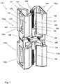
- Fig. 1 shows a connecting device 10 according to a first embodiment in a first functional position.
- This functional position is a position in which the connecting device 10 is in a partially open or relaxed position. In this position it is possible to connect the connecting device 10 to the desired element, such as a component or pontoon element, to which it is to be connected.
- Fig. 2 is the connecting device of the Fig. 1 shown in a partially closed or tensioned or assembled state, in which the connecting device 10 connects two components to one another.
- the connecting device 10 comprises two block-like base bodies 12a, 12b each with an upper side 16a, 16b, a lower side 18a, 18b, a first end side 20a, 20b, a second end side 22a, 22b, and two opposite longitudinal sides 24a, 24b.
- the two block-like base bodies 12a, 12b are constructed identically. They are arranged one above the other and parallel to one another at a distance from one another and are connected to one another via a holder 26, the two undersides 18a, 18b of the base body 12a, 12b being opposite one another. In this arrangement, the top side 16a of the first base body 12a and the top side 16b of the second base body 16b each point outwards.
- the base body 12a, 12b has a middle section 28a, 28b and two end sections 30a, 30b which are opposite to the middle section 28a, 28b.
- the first and second end faces 20a, 20b, 22a, 22b of the base body 12a, 12b are at the same time the first and second end faces, respectively, of the end section 30a, 30b.
- the base body 12a, 12b tapers from one end section 30a, 30b of the base body 12a, 12b to the middle section 28a, 28b of the base body 12a, 12b and then widens again in the direction of the other end section 30a, 30b of the base body 12a, 12b.
- the longitudinal sides 24a, 24b are beveled in the end section of the base body 12.
- the base body 12a, 12b thus has an axially symmetrical funnel shape.
- a groove 32a, 32b On each end face 20a, 20b, 22a, 22b of the base body 12a, 12b, a groove 32a, 32b is provided which has a T-shaped cross section, extends from the top side 16a, 16b to the bottom side 18a, 18b of the base body 12a, 12b and is open to the top 16a, 16b and bottom 18a, 18b of the base body 12a, 12b.
- Each groove 32a, 32b has a predetermined inclination with respect to the end face 20a, 20b, 22a, 22b of the base body 12a, 12b.
- a connecting unit 34 is provided on each end face of the two base bodies 20a, 20b, 22a, 22b.
- connection unit 34 comprises a fastening element 36, an adjustment body 38 and an adjustment device.
- the adjusting device in turn comprises an adjusting rod 40 and an adjusting means.
- connection unit 34 on an end face 20a, 20b, 22a, 22b of the base body 12a, 12b is described below.
- the fastening element 36 has a block-like basic structure with a beveled side surface 44.
- the fastening element 36 is arranged on the end face 20a, 20b, 22a, 22b of the base body 12a, 12b, the beveled side surface 44 of the fastening element 36 facing the end face 20a, 20b, 22a, 22b of the base body 12a, 12b has.
- a T-shaped groove 46 is provided which is inclined in a mirror-inverted manner to the groove 32a, 32b in the base body 12a, 12b.
- two parallel and spaced-apart connecting rods 48 are provided perpendicular to the end face 20a, 20b, 22a, 22b of the base body 12a, 12b.
- the connecting rods 48 connect the fastening element 36 and the base body 12a, 12b 12a, 12b, one end of each connecting rod being firmly connected to the base body 12a, 12b and the other end of the connecting rod 48 being slidably mounted in an opening in the fastening element 36.
- the two connecting rods 148 thus form a connecting part with the aid of which the fastening element 36 can be displaced along the connecting rod 48 in order to be able to vary the distance between the fastening element 36 and the base body 12a, 12b.
- the connecting rod 48 ensures that the fastening element 36 and the base body 12a, 12b always move in the same plane.
- the connecting rod 48 is firmly connected to the fastening element 36 and is arranged displaceably in an opening of the base body 12a, 12b.
- the adjustment body 38 is arranged between the base body 12a, 12b and the fastening element 36 and between the two parallel connecting rods 48. It is designed as a wedge-shaped block with a longitudinal axis, the wedge tip pointing to the top side 16a, 16b of the base body 12a, 12b.
- the adjustment body 38 has two opposite longitudinal sides 52, two opposite transverse sides 54, an upper side 56 and a lower side 58. Furthermore, a through-hole 60 with a thread pointing parallel to the longitudinal axis of the adjustment body 38 is provided.
- the transverse sides 54 of the adjustment body 38 are inclined with respect to the longitudinal axis of the adjustment body 38 and thus with respect to the through hole 60.
- the angle of inclination of the transverse sides 54 corresponds to the angle of inclination of the groove 46 in the fastening element 36 or the angle of inclination of the groove 32a, 32b in the base body 12a, 12b, so that the transverse sides of the adjustment body 38 along the end face 20a, 20b, 22a, 22b of the Base body 12a, 12b or can slide along the beveled side surface 44 of the fastening element 36.
- the Transverse sides 54 of the adjustment body 38 form contact sides to the fastening element 36 or the base body 12a, 12b.
- Guide strips 62 are provided on the respective end sections of the longitudinal sides of the adjustment body 38 and extend along the two inclined edges of the two longitudinal sides 52 of the adjustment body 38.
- the adjusting body 38 thus has a double-T-shaped contour.
- the size of the guide strips 62 and the width of the transverse sides 54 of the adjustment body 38 are selected so that the end section can be moved precisely in the T-shaped groove 46 of the fastening element 36 or in the T-shaped groove 32a, 32b of the base body 12a, 12b .
- the end section of the adjustment body 38 thus forms a profile element which can be displaced in the T-shaped groove 46 of the fastening element 36 or in the T-shaped groove 32a, 32b of the base body 12a, 12b.
- the profile element forms a linear guide unit, the guide strips 62 serving as lateral guides.
- the guide strips 62 are thus also part of a counter-guide element for the guide element designed as a groove 32a, 32b.
- the adjusting rod 40 has a threaded section 64 (see FIG Fig. 2 ) on.
- other known adjusting means such as handles, can also be used.
- One end section of the adjusting rod 40 is located in the through-hole 60 of the adjusting body 38, the threaded section 64 of the adjusting rod 40 interacting with the thread of the through-hole 60 and the wedge-shaped end of the adjusting body 38 pointing towards the end of the adjusting rod 40.
- a fixing element 68 is provided which is fastened to the holder 26 and has a passage 70 for the adjusting rod 40.
- the adjusting rod 40 is rotatably mounted in the passage 70 of the fixing element 68.
- a blocking against a longitudinal displacement of the adjusting rod 40 in the fixing element 68 is provided.
- the blocking is formed in that the adjusting rod 40 has a recess 72 on its outside.
- the recess 72 is designed in a ring shape on the outside of the adjusting rod 40, the fixing element 68 being positioned in sections in the recess 72.
- the screw 66 is rotated by means of a corresponding tool, so that the adjusting rod 40 is rotated. Since the adjusting rod 40 rotates, but is not longitudinally displaceable, the adjusting body 38 slides along the Adjusting rod 40. Depending on the direction of rotation of the adjusting rod 40, the adjusting body 38 slides either in the direction of the top side 16a, 16b or the bottom side 18a, 18b of the base body 12a, 12b.
- the distance between the base body 12a, 12b and the fastening element 36 is increased because the adjustment body is driven in a wedge-like manner between the base body 12a, 12b and the fastening element 36. Since the base body 12a, 12b and the fastening element 36 are connected to one another via the connecting rods 48, the base body 12a, 12b and the fastening element 36 remain in one plane during the adjustment process.
- the connecting device 10 is in its closed position ( Fig. 2 ) brought.
- the adjustment body 38 slides along the guide strips 62 on the fastening element 36 or on the base body 12a, 12b. Since the fastening element 36 can only perform a movement perpendicular to the longitudinal axis of the connecting rod 48 due to the connecting rod 48, the movement of the adjusting body 38 in the direction of the underside 18a, 18b of the base body 12a, 12b causes the fastening element 36 to be pulled onto the base element 12a, 12b and the distance between the fastening element 36 and the base element 12a, 12b is reduced. The connecting device 10 is thereby moved from a closed position to an open position ( Fig. 1 ) brought.
- FIG. 1 and 2 the end positions of a closed position or an open position of the connecting device 10 are not shown. In many applications it is not necessary to transfer the connecting device 10 from a completely closed position to an open position or vice versa. A partially open position is often sufficient to position a connection device 10 or a partially closed position to fix a connection device 10 on a component.
- a connecting unit 34 is provided on each of the four end faces of the base body 12a, 12b.
- the two adjustment rods 40 on the first end face 20a, 20b of the first and second base body 12a, 12b and the two adjustment rods on the second end face 22a, 22b of the first and second base body 12a, 12b are integrally connected to one another.
- Each adjusting rod 40 thus has threaded sections 64 at both of its ends.
- the length of each adjusting rod 40 is selected such that the end sections of the adjusting rods 40 provided with the thread are respectively are arranged at least in sections in the bore of the adjustment body 38.
- the adjustment means can be provided on both end faces of the adjustment rod 40.
- each connecting unit 34 point with the wedge tip outwards in the direction of the top side 16a, 16b of the base body 12a, 12b, so that the connecting device 10 is axially symmetrical with respect to an axis parallel to the longitudinal axis of the adjusting rod 40 and axially symmetrical with respect to an axis perpendicular to the longitudinal axis of the adjusting rod 40 is formed.
- both adjusting bodies 38 connected to the adjusting rod 40 move the correspondingly assigned fastening body 36 in the same direction. Both fastening bodies 36 can thus be brought from an open to a closed position or vice versa at the same time.
- Each pontoon element 80 comprises a recess 82.
- the recess 82 is designed as a groove 84 open at both ends.
- the cross section of the groove 84 has a basic shape which is essentially complementary to one half of the contour of the connecting device 10 in cross section.
- Two pontoon elements 80 arranged next to one another thus have a recess 82 which essentially corresponds to the contour of the cross section of the connecting device 10.
- the groove 84 has a groove opening 86 which has a smaller width than the groove 84 in the interior.
- the width of the groove opening 86 is somewhat larger than the width of the central section 28a, 28b of the base body 12a, 12b, so that there is play here.
- the groove 84 has inclined wall sections 88 on which the inclined longitudinal sides 24a, 24b of an end section 30a, 30b of the base body 12a, 12b rest.
- the inclined wall sections 88 of the groove 84 form a stop surface for the inclined longitudinal sides 24a, 24b of the connecting device 10, so that a section of the connecting device 10 can be firmly attached, in particular clamped, in the recess 82 or groove 84 of the pontoon element 80.
- the two pontoon elements 80 are placed against one another and the connecting device 10 is inserted from the top of the pontoon elements 80 with play into the recesses 82 of the two pontoon elements 80.
- Fig. 5 the state in which the connecting device 10 is located inside the two recesses 82 of the pontoon elements 80 to be connected can be seen.
- the connecting device 10 is located in the recesses 82 of the pontoon elements 80 in its clamped or closed position, the fastening element resting against the inside of the groove 84 so that the two pontoon elements are firmly connected to one another.
- connection device 10 has the in Fig. 1 unopened condition shown.
- the connecting device 10 can be operated as described above in order to clamp the two pontoon elements 80 firmly together (see Fig. 6 ).
- connection units 34 on two base bodies 12a, 12b arranged one above the other has the advantage that the pontoon elements 80 can be held in a rotationally secure manner.
- the risk of two pontoon elements 80 connected to one another rotating about their connecting axis is very low with this connecting device 10.
- a component such as a railing or a post can be provided on an end face of the base body, so that, for example, components can be attached to pontoon elements.
- a base body and the corresponding connection units provided on the base body can be omitted, so that the connection device comprises only one base body, on the two end faces of which a connection unit can be provided.
- This embodiment is useful when the height of the components to be connected is low.
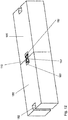
- Fig. 7 shows a connecting device 110 according to a second embodiment in a first functional position.
- This functional position is a position in which the connecting device 110 is in a partially open or relaxed position. In this position it is possible to connect the connecting device 110 to the desired element, such as a component or pontoon element, to which it is to be connected.
- Fig. 8 is the connecting device of the Fig. 7 shown in a partially closed or tensioned or assembled state, in which the connecting device 110 connects two components to one another.
- the connecting device 110 comprises two base bodies 112a, 112b which are arranged one above the other and which are connected to one another in one piece.
- a connecting unit 134a, 134b is provided on each base body 112a, 112b.
- Each connecting unit 134a, 134b comprises a fastening element 136a, 136b, the two fastening elements 136a, 136b being firmly connected to one another.
- the two interconnected fastening elements 136a and 136b and the two interconnected base bodies 112a, 112b are of identical construction and are therefore interchangeable with one another.
- Each fastening element 136a, 136b has the basic shape of a hollow profile element open on one side with a rear wall 137 and two side walls 139, which is C-shaped in cross section.
- the rear wall 137 of the fastening element 136a, 136b forms a wall on which guide elements are provided.
- the guide elements are formed by the two side walls 139 of the fastening element 136a, 136b, the side walls 139 each having a first section 141 which is oriented perpendicular to the rear wall 137 and a second section 143 which is bent inward relative to the first section 141.
- the inside of the rear wall 137 and the inside of the side walls 139 form a groove in which the adjusting element 138 can be displaced.
- the outer wall of the second section 143 serves, as described further below, as a stop surface for a component.
- the base body 112a, 112b and the fastening element 136a, 136b are arranged such that their open sides face one another.
- An adjustment body 138 is provided between each base body 112a, 112b and fastening element 136a, 136b, which is slidably mounted in the fastening element 136a, 136b or base body 112a, 112b, the adjustment body 138 being guided along the side guides 145.
- the adjustment body 138 has, seen in cross section, a central section 151 and two end sections 153 which are aligned opposite to one another (see FIG Fig. 8 ).
- the end sections 153 each have a contour that is complementary to the cross section of the fastening element 136a, 136b or the base body 112a, 112b, so that the fastening element 136a, 136b or the base body 112a, 112b the respective end sections 153 of the adjustment body 138 encompass.
- the adjusting body 138 has a through-hole 160 with a thread along its longitudinal axis, in which an adjusting rod 140 in the form of a spindle is rotatably guided.
- the transverse sides of the adjustment body 138 which point towards the base body 112a, 112b or fastening element 136a, 136b, are inclined with respect to the longitudinal axis of the adjustment body 138.
- the adjustment body 138 has a wedge-shaped basic shape, the wedge tips of both adjustment bodies 138, in contrast to the first embodiment of the adjustment device 10, each pointing inward or facing one another. Viewed in the longitudinal direction of the adjustment body 138, the adjustment body 138 has a shorter length than the fastening element 136a, 136b.
- the two spindles of the connecting device 110 are integrally connected to one another and are rotatably but stationary in a fixing element 168 which is provided between the two base bodies 112a, 112b or between the two fastening elements 136a, 136b.
- a fixing element 168 which is provided between the two base bodies 112a, 112b or between the two fastening elements 136a, 136b.
- corresponding blocking elements are provided.
- the base body 112a, 112b and the fastening element 136a, 136b are connected to one another via connecting rods 148 which are perpendicular to the spindle.
- the connecting rods 148 are arranged in the fixing element 168, which supports the spindle in a rotatable and stationary manner.
- adjusting screws 166 are provided at the free ends of the adjusting rod 140. If these are rotated, both adjusting elements 138 move along the spindles. Depending on the direction of rotation, the two adjusting bodies 138 move towards or away from one another.
- each adjustment body 138 presses the main body 112a, 112b resting against it and the fastening element 136a, 136b resting against it apart, so that the connecting device moves into its open or first functional position.
- the connecting rods 148 ensure that the fastening element 136a, 136b and the base body 112a, 112b move in one plane.
- each adjustment body 138 pulls the base body 112a, 112b resting against it and the fastening element 136a, 136b resting against it towards one another by guiding the adjustment body 138 along the inclined side guides 145.
- the connecting device 110 is in its clamped or second functional position.
- the connecting device 110 is inserted and prepositioned in two opposing recesses 182 of two components arranged next to one another, such as pontoon elements 180.
- the two opposing recesses 182 have the same contour in cross section as the connecting device 110.
- the recess 182 is designed as a groove open at both ends and thus has a rear wall 183 and two side walls, each side wall having a first, perpendicular to the rear wall standing section 185 and a second section 187 bent relative to the first section.
- the distance between the fastening element 136a, 136b and the base element 112a, 112b is greater than in the clamped or second functional position. There is a gap between the two pontoon elements 182.
- the spindle is rotated by means of the adjusting screw 166 located on the end face of the spindle and the fastening element 136a, 136b and the base body 112a, 112b approach.
- the beveled side surfaces 141 of the fastening element 136a, 136b or of the base body 112a, 112b rest on the beveled second section 187 of the side wall of the recess 182.
- the two pontoon elements 182 rest against one another without a gap.
- a connecting device can be omitted in a variant not shown, one of the two base bodies and the corresponding connecting unit.
- connection is also not, as shown, limited to the transverse sides of the pontoon element.
- the pontoon elements also have corresponding recesses on the longitudinal sides, so that not only elongated but also flat pontoon bridge elements can be produced.
- the connecting devices can also be used on any other structural elements that have a corresponding recess for receiving at least one section of the connecting device.
Landscapes
- Engineering & Computer Science (AREA)
- General Engineering & Computer Science (AREA)
- Mechanical Engineering (AREA)
- Architecture (AREA)
- Civil Engineering (AREA)
- Structural Engineering (AREA)
- Bridges Or Land Bridges (AREA)
Abstract
Description
- Die vorliegende Erfindung betrifft eine Verbindungsvorrichtung sowie ein Bauteil, das mit der Verbindungsvorrichtung verbunden ist, insbesondere betrifft die Erfindung ein Pontonelement, das mit der Verbindungsvorrichtung verbunden ist, sowie eine entsprechende Pontonbrücke.
- Pontonbrücken bestehen in der Regel aus einzelnen Pontonelementen, die miteinander verbunden sind. Jedes einzelne Pontonelement ist hierbei ein eigener Schwimmkörper.
- Pontonbrücken haben im Vergleich zu klassischen Brücken den Vorteil, dass sie schnell und günstig gebaut werden können. Da Pontonbrücken in der Regel aus Einzelelementen zusammengesetzt sind, können sie sehr flexibel gestaltet und somit für unterschiedlichste Zwecke eingesetzt werden.
- So finden Pontonbrücken beispielsweise Anwendung bei der Überquerung eines Flusses, wenn aufgrund des Untergrunds eine feste Brücke nicht oder nur mit unverhältnismäßig großem Aufwand gebaut werden könnte. Darüber hinaus werden Pontonbrücken dann eingesetzt, wenn beispielsweise aufgrund von Zerstörungen einer Brücke nach Naturkatastrophen oder Kriegseinsätzen schnell ein Ersatz zur Verfügung stehen muss.
- In vielen Fällen sind Pontonbrücken provisorische Brücken. In einigen Fällen könne diese jedoch auch eine Dauerlösung sein.
- Darüber hinaus werden Pontonplattformen in Ufernähe eingesetzt. Der Vorteil solcher Pontonplattformen liegt darin, dass sie sich mit steigendem bzw. fallendem Wasserstand heben bzw. senken. Diese Eigenschaft wird insbesondere bei Anlegestellen von Booten genutzt, so dass die Boote und die Anlegestellen bei wechselndem Wasserstand im Wesentlichen immer die gleiche Höhe haben.
- Die Vielzahl von Anwendungsmöglichkeiten und die hohe Flexibilität der Pontonbrücke sind u.a. auch darauf zurückzuführen, dass einzelne Pontonelemente flexibel verknüpft werden können, um eine Anpassung der Pontonbrücke bzw. Pontonplattform an die äußeren Gegebenheiten vornehmen zu können.
- Da die Pontonbrücken bzw. Pontonplattformen hohen Belastungen ausgesetzt sind, beispielsweise aufgrund von die Brücke querenden Fahrzeugen, Wind oder wechselnden Wasserständen, bestehen hohe Anforderungen an die Stabilität der Verbindung der einzelnen Pontonelemente zur Ausbildung einer Pontonbrücke bzw. Pontonplattform. Insbesondere muss die Verbindung zwischen einzelnen Pontonelementen hohe Kräfte aufnehmen können. Werden Pontonbrücken beispielsweise als Ersatzbrücken für zerstörte Brücken benötigt oder ist eine rasche Überquerung eines Flusses an Stellen notwendig, an denen keine Brücken existieren, so besteht neben der Anforderung an eine hohe Stabilität der Verbindung zwischen den Pontonelementen auch noch die Anforderung, die Pontonelemente schnell miteinander verbinden zu können.
- Es ist Aufgabe der vorliegenden Erfindung, eine Verbindungsvorrichtung bereitzustellen, mit Hilfe deren es möglich ist, Bauteile, insbesondere Pontonelemente schnell und sicher miteinander zu verbinden. Darüber hinaus ist es Aufgabe der Erfindung, eine stabile Pontonbrücke bzw. Pontonplattform bereitzustellen, die auch hohen Belastungen standhält.
- Erfindungsgemäß wird die Aufgabe gelöst durch eine Verbindungsvorrichtung gemäß Anspruch 1 sowie eine Pontonbrücke mit wenigstens einem Pontonelement, das mit einer solchen Verbindungsvorrichtung verbunden ist.
- Die erfindungsgemäße Verbindungsvorrichtung umfasst wenigstens einen Grundkörper und wenigstens eine Verbindungseinheit mit einem Befestigungselement, einem Verstellkörper mit einer Längsachse und einer Verstellvorrichtung, wobei der Abstand zwischen dem Befestigungselement und dem Grundkörper veränderbar ist, wobei der Grundkörper eine Wand mit einem ersten Führungselement aufweist, wobei das Befestigungselement eine Wand mit einem zweiten Führungselement aufweist, wobei die Wand des Grundkörpers, an der das erste Führungselement vorgesehen ist, und die Wand des Befestigungselements, an der das zweite Führungselement vorgesehen ist, zueinander weisen, wobei der Verstellkörper zwischen dem Grundkörper und dem Befestigungselement angeordnet ist und über eine erste Querseite verfügt, die zum Grundkörper weist, sowie über eine zweite Querseite, die zum Befestigungselement weist, wobei der Verstellkörper mittels der Verstellvorrichtung entlang einer Achse parallel zur Längsachse des Verstellkörpers verschiebbar ist und ein Gegenführungselement aufweist, das mit dem ersten oder zweiten Führungselement wechselwirkt, und wobei das Gegenführungselement des Verstellkörpers gegenüber der Längsachse des Verstellkörpers geneigt ist.
- Bei der Verbindungsvorrichtung handelt es sich im Wesentlichen um eine Klemmvorrichtung. Mit Hilfe des Verstellkörpers ist es möglich, den Abstand zwischen dem Grundkörper und dem Befestigungselement zu verändern, so dass hierdurch eine Klemmverbindung erzielt werden kann.
- Der Verstellkörper wird mittels der Verstellvorrichtung senkrecht zu der von dem Grundkörper und dem Befestigungselement gebildeten Achse verschoben. Dadurch, dass der Verstellkörper ein Gegenführungselement aufweist, das gegenüber der Längsachse des Verstellkörpers geneigt ist, treibt der Verstellkörper den Grundkörper und das Befestigungselement in der Art eines Keils auseinander, wenn dieser in einer vorgegebenen Richtung entlang einer Achse parallel zur Längsachse des Verstellkörpers verschoben wird. Hierbei kann der Verstellkörper beispielsweise selbst als Keil mit geneigten Querseiten ausgebildet sein, wobei die Querseiten bereits als Gegenführungselement dienen können.
- Bei einer bevorzugten Ausführungsform umfasst die Verstellvorrichtung eine Verstellstange und ein Verstellmittel, wobei die Verstellstange mit dem Verstellkörper verstellbar, insbesondere verdrehbar verbunden ist. Das Verstellmittel kann beispielsweise eine Schraube oder ein Griff an der Stirnseite der Verstellstange sein. Mit Hilfe des Verstellmittels lässt sich die Verstellstange betätigen, so dass der mit der Verstellstange verbundene Verstellkörper einfach verschoben werden kann. Ein besonders gleichmäßiges und kontrolliertes Verschieben des Verstellkörpers entlang der Verstellstange lässt sich beispielsweise dadurch erreichen, dass der Verstellkörper eine Bohrung aufweist und die Verstellstange in der Bohrung drehbar angeordnet ist, wobei in der Bohrung ein Gewinde vorgesehen ist und zumindest der Abschnitt der Verstellstange, der in der Bohrung gelagert wird, einen Gewindeabschnitt aufweist.
- Um sicherzustellen, dass bei dieser Ausführungsform der Verstellkörper entlang der Verstellstange verschoben wird und nicht die Verstellstange selbst, ist ein Fixierungselement vorgesehen, in dem die Verbindungsstange ortsfest und drehbar gelagert ist.
- Es ist von Vorteil, dass das erste Führungselement mit einem ersten Gegenführungselement am Verstellkörper und/oder das zweite Führungselement mit einem zweiten Gegenführungselement am Verstellkörper wechselwirken, wobei das erste Führungselement und das erste Gegenführungselement eine lineare Führungseinheit bilden und/oder das zweite Führungselement und das zweite Gegenführungselement eine lineare Führungseinheit bilden. Hierdurch wird sichergestellt, dass der Verstellkörper zuverlässig entlang eines vorgegebenen Verschiebewegs geführt werden kann und die Verbindungsvorrichtung beispielsweise auch in optisch nicht kontrollierbaren Anwendungen eingesetzt werden kann.
- Hierbei hat es sich als vorteilhaft erwiesen, dass das erste Führungselement und das erste Gegenführungselement im Querschnitt komplementär zueinander ausgebildet sind und/oder das zweite Führungselement und das zweite Gegenführungselement im Querschnitt komplementär zueinander ausgebildet sind.
- Hierbei ist es besonders bevorzugt, dass das Führungselement oder das Gegenführungselement als Nut ausgebildet ist, wobei vorzugsweise wenigstens eine Seitenwand der Nut eine Seitenführung aufweist. Eine beispielsweise entlang der Wand des Grundkörpers und/oder entlang der Wand des Befestigungselements vorgesehene Nut führt den Verstellkörper sicher in seiner Bewegung parallel zu seiner Längsachse. Die Seitenführungen, die beispielsweise in der Nut als Vertiefungen in der Seitenwand der Nut vorgesehen sein können, sorgen dafür, dass der Verstellkörper sicher an dem Befestigungselement bzw. dem Grundkörper gehalten wird und sich insbesondere nicht in einer Ebene senkrecht zur seiner Längsachse verschiebt.
- Um eine Klemmverbindung mit einem kontrollierbaren Anpressdruck zu erhalten, ist es vorteilhaft, dass das Führungselement und das Gegenführungselement jeweils einen Führungsabschnitt aufweisen, der über die gleiche Neigung gegenüber der Längsachse des Verstellkörpers verfügt.
- Bei einer Ausführungsform, bei der das Führungselement und/oder das Gegenführungselement geneigte Seitenführungen aufweist, die beispielsweise in der Seitenwand einer Nut vorgesehen sind, ist es möglich, mittels des Verstellkörpers den Abstand zwischen Befestigungselement und Grundkörper so zu verändern, so die Verstellvorrichtung von einer geöffneten in eine geschlossene Stellung und umgekehrt überführbar ist.
- Unter einer geöffneten Stellung wird eine Stellung verstanden, in der die Verbindungsvorrichtung nicht an einem Element befestigt ist. Sie kann auch als entspannte Stellung bezeichnet werden. Eine geschlossene oder verspannte Stellung ist eine Stellung, in der die Verbindungsvorrichtung mit einem Element verbunden ist.
- Es ist bevorzugt, dass ein Verbindungsteil vorgesehen ist, welches das Befestigungselement und den Grundkörper direkt oder indirekt verbindet, wobei das Verbindungsteil vorzugsweise eine Verbindungsstange aufweist. Wenn eine Verbindungsstange vorgesehen ist, die das Befestigungselement und den Grundkörper miteinander verbindet, können das Befestigungselement und/oder der Grundkörper entlang der Verbindungsstange verschoben werden. Diese Verbindungsstange sorgt dafür, dass das Befestigungselement senkrecht zur Längsachse des Verstellkörpers verschoben wird, um den Abstand zwischen Grundkörper und Verstellkörper zu verändern, während das Befestigungselement und der Grundkörper in der gleichen Ebene gehalten werden.
- Bei einer bevorzugten Ausführungsform weisen das Befestigungselement und der Grundkörper die gleiche Form auf. In diesem Fall kann der Grundkörper die gleiche Funktion wie das Befestigungselement übernehmen. Bei dieser Ausführungsform kann die Verbindungsvorrichtung darüber hinaus sehr kompakt gestaltet werden.
- Bei einer weiteren Ausführungsform ist der Grundkörper blockartig ausgebildet, wobei der Grundkörper einen mittleren Abschnitt und zwei entgegengesetzt liegende Endabschnitte aufweist, wobei an einem Endabschnitt die Verbindungseinheit und an dem entgegengesetzt liegenden Endabschnitt eine weitere Verbindungseinheit oder ein Bauteil vorgesehen sind. Der Grundkörper kann hierbei als eine Art Adapter für verschiedene Bauteile dienen, so dass beispielsweise ein Pontonelement mit einem Bauteil wie etwa einem Geländer verbunden werden kann. Aufgrund des Vorsehens eines Grundkörpers können verschiedene Element wie etwa Pontonelemente mit Abstand voneinander miteinander verbunden werden.
- Bei einer bevorzugten Weiterbildung erweitert sich der Grundkörper zu zumindest einem Endabschnitt. Beispielsweise kann der Grundkörper sich zu einer Seite trichterförmig erweitern Diese geometrische Form ist insbesondere dann von Vorteil, wenn an dem Element, an dem die Verbindungsvorrichtung angebracht werden soll, eine Aussparung mit einem im Wesentlichen komplementären Querschnitt vorgesehen ist. Dies ermöglicht eine einfache Positionierung der Verbindungsvorrichtung an dem Element, an dem sie angebracht werden soll, da die Bewegung der Verbindungsvorrichtung gegenüber dem Element, mit dem sie verbunden werden soll, bereits in zwei Raumrichtungen eingeengt wird.
- Es ist von Vorteil, dass zwei Grundkörper übereinander und im Abstand voneinander angeordnet sind, wobei die beiden Grundkörper miteinander verbunden sind. Hierbei können Verbindungsvorrichtungen bereitgestellt werden, die in vertikaler Richtung zwei übereinander angeordnete Grundelemente mit entsprechenden Verbindungseinheiten aufweisen, um hohe Elemente, wie etwa hohe Pontonelemente, sicher, insbesondere drehsicher an ihren Seitenwänden miteinander zu verbinden.
- Bei dieser Ausführungsform ist es besonders bevorzugt, dass das Befestigungselement der am ersten Grundkörper vorgesehenen Verbindungseinheit und das Befestigungselement der am zweiten Grundkörper vorgesehenen Verbindungseinheit mittels einer gemeinsamen Verstellvorrichtung verschiebbar sind und die erste Verbindungseinheit achssymmetrisch zur zweiten Verbindungseinheit ausgebildet ist. Mit Hilfe dieser Anordnung ist es möglich, beide Verbindungseinheiten gleichzeitig so zu betätigen, dass sie gleichzeitig von einer geöffneten Stellung in eine geschlossene Stellung und umgekehrt überführbar sind.
- Gegenstand der vorliegenden Erfindung ist eine Pontonbrücke, umfassend wenigstens ein Pontonelement und wenigstens eine Verbindungsvorrichtung gemäß der vorliegenden Erfindung, wobei vorzugsweise wenigstens zwei Pontonelemente vorgesehen sind, die mittels einer Verbindungsvorrichtung miteinander verbunden sind.
- Der Begriff Pontonbrücke umfasst hier nicht nur brückenartige Gebilde sondern auch Plattformen in Ufernähe. Aus sprachlichen Gründen wurde nur der Begriff Pontonbrücke gewählt.
- Es ist von Vorteil, dass das Pontonelement eine Aussparung zur Aufnahme eines Abschnitts der Verbindungsvorrichtung aufweist, wobei der in der Aussparung aufgenommene Abschnitt der Verbindungsvorrichtung in der Aussparung verklemmbar ist. Hierdurch lässt sich die Verbindungsvorrichtung sicher an dem Pontonelement halten.
- Bei einer bevorzugten Weiterbildung verfügt die Aussparung zur Aufnahme eines Abschnitts der Verbindungsvorrichtung im Querschnitt über eine Kontur, deren Grundform komplementär zu der Kontur des Abschnitts der Verbindungsvorrichtung ist, welche in der Aussparung des Pontonelements angeordnet ist. Wie bereits oben angeführt kann dadurch eine einfache Vorpositionierung der Verbindungsvorrichtung an dem Pontonelement vorgenommen werden
- Vorzugsweise weist die Aussparung eine Anschlagfläche für die wenigstens eine Verbindungseinheit auf. Insbesondere weist die Rückwand und/oder die Seitenwand der Aussparung eine Anschlagfläche für das Befestigungselement auf. Hierdurch kann auf eine Vielzahl zusätzlicher Befestigungsmaßnahmen verzichtet werden und es reicht eine Klemmverbindung, um die Verbindungsvorrichtung sicher an dem Pontonelement zu halten.
- Die Aussparung ist beispielsweise eine an ihren beiden Endabschnitten offene Nut mit einer in Längsrichtung nach außen weisenden Öffnung, wobei die Nut im Inneren zumindest abschnittsweise breiter ist als die Öffnung der Nut.
- Bevorzugte Ausführungsformen werden anhand der beigefügten Zeichnungen näher erläutert, in denen zeigen:
- Fig. 1
- eine erste Ausführungsform einer Verbindungsvorrichtung in einer ersten Funktionsstellung,
- Fig. 2
- die in
Fig. 1 dargestellte Verbindungsvorrichtung in einer zweiten Funktionsstellung, - Fig. 3
- Teile einer Pontonbrücke,
- Fig. 4
- einen Montageschritt zum Verbinden zweier Pontonelemente zu einer Pontonbrücke mit einer Verbindungsvorrichtung gemäß einer ersten Ausführungsform,
- Fig. 5
- zwei miteinander verbundene Pontonelemente in einer vorpositionierten Stellung,
- Fig. 6
- zwei fest miteinander verbundene Pontonelemente,
- Fig. 7
- eine zweite Ausführungsform einer Verbindungsvorrichtung in einer ersten Funktionsstellung,
- Fig. 8
- die in
Fig. 7 dargestellte Verbindungsvorrichtung in einer zweiten Funktionsstellung, - Fig. 9
- Teile einer Pontonbrücke,
- Fig. 10
- einen Montageschritt zum Verbinden zweier Pontonelemente zu einer Pontonbrücke mit einer Verbindungsvorrichtung gemäß einer ersten Ausführungsform,
- Fig. 11
- zwei miteinander verbundene Pontonelemente in einer vorpositionierten Stellung und
- Fig. 12
- zwei fest miteinander verbundene Pontonelemente.
-
Fig. 1 zeigt eine Verbindungsvorrichtung 10 gemäß einer ersten Ausführungsform in einer ersten Funktionsstellung. Bei dieser Funktionsstellung handelt es sich um eine Stellung, in der die Verbindungsvorrichtung 10 sich in einer teilweise geöffneten oder entspannten Stellung befindet. In dieser Stellung ist es möglich, die Verbindungsvorrichtung 10 mit dem gewünschten Element wie etwa einem Bauteil oder Pontonelement, mit welchem es verbunden werden soll, zu verbinden. - In
Fig. 2 ist die Verbindungsvorrichtung derFig. 1 in einem teilweise geschlossenen bzw. verspannten oder montierten Zustand gezeigt, in dem die Verbindungsvorrichtung 10 zwei Bauteile miteinander verbindet. - Die Verbindungsvorrichtung 10 umfasst zwei blockartige Grundkörper 12a, 12b jeweils mit einer Oberseite 16a, 16b, einer Unterseite 18a, 18b, einer ersten Stirnseite 20a, 20b, einer zweiten Stirnseite 22a, 22b, und zwei entgegengesetzt liegenden Längsseiten 24a, 24b.
- Die beiden blockartigen Grundkörper 12a, 12b sind identisch aufgebaut. Sie sind übereinander und parallel zueinander mit Abstand voneinander angeordnet und über eine Halterung 26 miteinander verbunden, wobei die beiden Unterseiten 18a, 18b des Grundkörpers 12a, 12b einander gegenüber liegen. Bei dieser Anordnung weisen somit die Oberseite 16a des ersten Grundkörpers 12a und die Oberseite 16b des zweiten Grundkörpers 16b jeweils nach außen.
- Der Grundkörper 12a, 12b weist einen Mittelabschnitt 28a, 28b und zwei bezüglich des Mittelabschnitts 28a, 28b entgegengesetzt liegende Endabschnitte 30a, 30b auf. Die erste und zweite Stirnseite 20a, 20b, 22a, 22b des Grundkörpers 12a, 12b sind gleichzeitig die erste bzw. zweite Stirnseite des Endabschnitts 30a, 30b. Der Grundkörper 12a, 12b verjüngt von sich von einem Endabschnitte 30a, 30b des Grundkörpers 12a, 12b zum Mittelabschnitt 28a, 28b des Grundkörpers 12a, 12b und erweitert sich dann wieder in Richtung des anderen Endabschnitts 30a, 30b des Grundkörpers 12a, 12b. Die Längsseiten 24a, 24b sind aufgrund dessen im Endabschnitt des Grundkörpers 12 abgeschrägt. Der Grundkörper 12a, 12b weist somit eine achssymmetrische Trichterform auf.
- An jeder Stirnseite 20a, 20b, 22a, 22b des Grundkörpers 12a, 12b ist eine Nut 32a, 32b vorgesehen, die einen T-förmigen Querschnitt aufweist, sich von der Oberseite 16a, 16b zur Unterseite 18a, 18b des Grundkörpers 12a, 12b erstreckt und zur Oberseite 16a, 16b und Unterseite 18a, 18b des Grundkörpers 12a, 12b offen ist. Jede Nut 32a, 32b weist gegenüber der Stirnseite 20a, 20b, 22a, 22b des Grundkörpers 12a, 12b eine vorgegebene Neigung auf.
- An jeder Stirnseite der beiden Grundkörper 20a, 20b, 22a, 22b ist eine Verbindungseinheit 34 vorgesehen.
- Jede Verbindungseinheit 34 umfasst ein Befestigungselement 36, einen Verstellkörper 38 und eine Verstellvorrichtung. Die Verstellvorrichtung umfasst wiederum eine Verstellstange 40 und ein Verstellmittel.
- Im Folgenden wird eine Verbindungseinheit 34 an einer Stirnseite 20a, 20b, 22a, 22b des Grundkörpers 12a, 12b beschrieben.
- Das Befestigungselement 36 hat eine blockartige Grundstruktur mit einer abgeschrägten Seitenfläche 44. Das Befestigungselement 36 ist an der Stirnseite 20a, 20b, 22a, 22b des Grundkörpers 12a, 12b angeordnet, wobei die abgeschrägte Seitenfläche 44 des Befestigungselements 36 zur Stirnseite 20a, 20b, 22a, 22b des Grundkörpers 12a, 12b weist.
- An der zum Grundkörper 12a, 12b weisenden Seite des Befestigungselements 36 ist eine T-förmige Nut 46 vorgesehen, die spiegelbildlich zu der Nut 32a, 32b im Grundkörper 12a, 12b geneigt ist.
- Zwischen dem Befestigungselement 36 und dem Grundkörper 12a, 12b sind senkrecht zur Stirnseite 20a, 20b, 22a, 22b des Grundkörpers 12a, 12b zwei parallel und im Abstand angeordnete Verbindungsstangen 48 vorgesehen. Die Verbindungsstangen 48 verbinden das Befestigungselement 36 und den Grundkörper 12a, 12b 12a, 12b, wobei das eine Ende jeder Verbindungsstange fest mit dem Grundkörper 12a, 12b verbunden ist und das andere Ende der Verbindungsstange 48 in einer Öffnung des Befestigungselements 36 verschiebbar gelagert ist. Die beiden Verbindungsstangen 148 bilden somit ein Verbindungsteil, mit Hilfe dessen sich das Befestigungselement 36 entlang der Verbindungsstange 48 verschieben lässt, um den Abstand zwischen Befestigungselement 36 und Grundkörper 12a, 12b variieren zu können. Die Verbindungsstange 48 sorgt dafür, dass das Befestigungselement 36 und der Grundkörper 12a, 12b sich immer in der gleichen Ebene bewegen.
- Bei einer nicht dargestellten Ausführungsform ist die Verbindungsstange 48 fest mit dem Befestigungselement 36 verbunden und verschiebbar in einer Öffnung des Grundkörpers 12a, 12b angeordnet.
- Der Verstellkörper 38 ist zwischen dem Grundkörper 12a, 12b und dem Befestigungselement 36 sowie zwischen den beiden parallelen Verbindungsstangen 48 angeordnet. Er ist als keilförmiger Block mit einer Längsachse ausgebildet, wobei die Keilspitze zur Oberseite 16a, 16b des Grundkörpers 12a, 12b zeigt.
- Der Verstellkörper 38 weist zwei entgegengesetzt liegende Längsseiten 52, zwei entgegengesetzt liegende Querseiten 54, eine Oberseite 56 und einer Unterseite 58 auf. Weiterhin ist eine parallel zur Längsachse des Verstellkörpers 38 weisende Durchgangsbohrung 60 mit einem Gewinde vorgesehen.
- Die Querseiten 54 des Verstellkörpers 38 sind gegenüber der Längsachse des Verstellkörpers 38 und somit gegenüber der Durchgangsbohrung 60 geneigt. Hierbei entspricht der Neigungswinkel der Querseiten 54 dem Neigungswinkel der Nut 46 in dem Befestigungselement 36 bzw. dem Neigungswinkel der Nut 32a, 32b in dem Grundkörper 12a, 12b, so dass die Querseiten des Verstellkörpers 38 entlang der Stirnseite 20a, 20b, 22a, 22b des Grundkörpers 12a, 12b bzw. entlang der abgeschrägten Seitenfläche 44 des Befestigungselements 36 gleiten können. Die Querseiten 54 des Verstellkörpers 38 bilden Kontaktseiten zu dem Befestigungselement 36 bzw. dem Grundkörper 12a, 12b.
- An den jeweiligen Endabschnitten der Längsseiten des Verstellkörpers 38 sind Führungsleisten 62 vorgesehen, die sich entlang der beiden schrägen Kanten der beiden Längsseiten 52 des Verstellkörpers 38 erstrecken. Im Querschnitt weist der Verstellkörper 38 somit eine doppel-T-förmige Kontur auf. Die Größe der Führungsleisten 62 und die Breite der Querseiten 54 des Verstellkörpers 38 sind so gewählt, dass der Endabschnitt passgenau in der T-förmigen Nut 46 des Befestigungselements 36 bzw. in der T-förmigen Nut 32a, 32b des Grundkörpers 12a, 12b verschiebbar ist. Der Endabschnitt des Verstellkörpers 38 bildet somit ein Profilelement, das in der T-förmigen Nut 46 des Befestigungselements 36 bzw. in der T-förmigen Nut 32a, 32b des Grundkörpers 12a, 12b verschoben werden kann. Das Profilelement bildet in Wechselwirkung mit den entsprechenden Nuten 32a, 32b, 36 eine lineare Führungseinheit, wobei die Führungsleisten 62 als Seitenführungen dienen. Die Führungsleisten 62 sind somit auch Teil eines Gegenführungselements für das als Nut 32a, 32b ausgebildete Führungselement.
- Die Verstellstange 40 weist an beiden Endabschnitten jeweils einen Gewindeabschnitt 64 (siehe
Fig. 2 ) auf. An zumindest einer Stirnseite der Verstellstange 40 ist ein Verstellmittel in Form einer Schraube 66, insbesondere eine Sechskantschraube angebracht. Anstelle der Schraube 66 können auch andere bekannte Verstellmittel wie etwa Griffe verwendet werden. - Ein Endabschnitt der Verstellstange 40 befindet sich in der Durchgangsbohrung 60 des Verstellkörpers 38, wobei der Gewindeabschnitt 64 der Verstellstange 40 mit dem Gewinde der Durchgangsbohrung 60 wechselwirkt und das keilförmige Ende des Verstellkörpers 38 in Richtung des Endes der Verstellstange 40 weist.
- Weiterhin ist ein Fixierungselement 68 vorgesehen, das an der Halterung 26 befestigt ist und einen Durchgang 70 für die Verstellstange 40 aufweist. Die Verstellstange 40 ist in dem Durchgang 70 des Fixierungselements 68 drehbar gelagert. Zusätzlich ist eine Blockierung gegen eine Längsverschiebung der Verstellstange 40 in dem Fixierungselement 68 vorgesehen. Die Blockierung wird dadurch gebildet, dass die Verstellstange 40 an ihrer Außenseite eine Vertiefung 72 aufweist. Die Vertiefung 72 ist ringförmig an der Außenseite der Verstellstange 40 ausgebildet, wobei das Fixierungselement 68 abschnittsweise in der Vertiefung 72 positioniert ist.
- Um die Verbindungseinheit 34 zu betätigen, wird die Schraube 66 mittels eines entsprechenden Werkzeugs gedreht, so dass die Verstellstange 40 gedreht wird. Da die Verstellstange 40 sich zwar dreht, aber nicht längsverschiebbar ist, gleitet der Verstellkörper 38 entlang der Verstellstange 40. Abhängig von der Drehrichtung der Verstellstange 40 gleitet der Verstellkörper 38 entweder in Richtung Oberseite 16a, 16b oder Unterseite 18a, 18b des Grundkörpers 12a, 12b.
- Gleitet der Verstellkörper 38 in Richtung Oberseite 16a, 16b des Grundkörpers 12a, 12b wird der Abstand zwischen Grundkörper 12a, 12b und Befestigungselement 36 vergrößert, da der Verstellkörper keilartig zwischen Grundkörper 12a, 12b und Befestigungselement 36 getrieben wird. Da der Grundkörper 12a, 12b und das Befestigungselement 36 über die Verbindungsstangen 48 miteinander verbunden sind, bleiben der Grundkörper 12a, 12b und das Befestigungselement 36 während des Verstellvorgangs in einer Ebene. Die Verbindungvorrichtung 10 wird in ihre geschlossene Stellung (
Fig. 2 ) gebracht. - Wird die Schraube 66 in umgekehrter Richtung gedreht und bewegt sich der Verstellkörper 38 in Richtung Unterseite 18a, 18b des Grundkörpers 12a, 12b, gleitet der Verstellkörper 38 entlang der Führungsleisten 62 an dem Befestigungselement 36 bzw. an dem Grundkörper 12a, 12b. Da das Befestigungselement 36 aufgrund der Verbindungsstange 48 nur eine Bewegung senkrecht zur Längsachse der Verbindungsstange 48 durchführen kann, führt die Bewegung des Verstellkörpers 38 in Richtung Unterseite 18a, 18b des Grundkörpers 12a, 12b dazu, dass das Befestigungselement 36 an das Grundelement 12a, 12b herangezogen wird und sich der Abstand zwischen Befestigungselement 36 und Grundelement 12a, 12b verringert. Die Verbindungsvorrichtung 10 wird dadurch von einer geschlossenen Stellung in eine geöffnete Stellung (
Fig. 1 ) gebracht. - Es sei angemerkt, dass in den
Fig. 1 und2 nicht die Endpositionen einer geschlossenen Stellung bzw. einer geöffneten Stellung der Verbindungsvorrichtung 10 dargestellt sind. Bei vielen Anwendungen ist es nicht notwendig, die Verbindungsvorrichtung 10 von einer vollständig geschlossenen Stellung in eine geöffnete Stellung bzw. umgekehrt zu überführen. Häufig reicht eine teilweise geöffnete Stellung, um eine Verbindungsvorrichtung 10 zu positionieren bzw. eine teilweise geschlossene Stellung um eine Verbindungsvorrichtung 10 an einem Bauteil zu fixieren. - Bei der in den
Fig. 1 und2 dargestellten Verbindungsvorrichtung ist an allen vier Stirnseiten des Grundkörpers 12a, 12b jeweils eine Verbindungseinheit 34 vorgesehen. Hierbei sind jeweils die beiden Verstellstangen 40 an der ersten Stirnseite 20a, 20b des ersten bzw. zweiten Grundkörpers 12a, 12b und die beiden Verstellstangen an der zweiten Stirnseite 22a, 22b des ersten bzw. zweiten Grundkörpers 12a, 12b einstückig miteinander verbunden. Jede Verstellstange 40 weist somit an ihren beiden Enden Gewindeabschnitte 64 auf. Die Länge jeder Verstellstange 40 ist so gewählt, dass die mit dem Gewinde versehenen Endabschnitte der Verstellstangen 40 jeweils zumindest abschnittsweise in der Bohrung des Verstellkörpers 38 angeordnet sind. Die Verstellmittel können an beiden Stirnseiten der Verstellstange 40 vorgesehen sein. - Die Verstellkörper 38 jeder Verbindungseinheit 34 weisen mit der Keilspitze nach Außen in Richtung der Oberseite 16a, 16b des Grundkörpers 12a, 12b, so dass die Verbindungsvorrichtung 10 achssymmetrisch bezüglich einer Achse parallel zur Längsachse der Verstellstange 40 sowie achssymmetrisch bezüglich einer Achse senkrecht zur Längsachse der Verstellstange 40 ausgebildet ist.
- Die führt dazu, dass beim Drehen der Verstellstange 40 mittels des Verstellmittels beide mit der Verstellstange 40 verbundenen Verstellkörper 38 den entsprechend zugeordneten Befestigungskörper 36 in die gleiche Richtung bewegen. Beide Befestigungskörper 36 können somit gleichzeitig von einer geöffneten in eine geschlossene Stellung oder umgekehrt gebracht werden.
- In den
Figuren 3 bis 6 ist ein Einsatz der Verbindungsvorrichtung 10 im Zusammenhang mit Pontonelementen 80 gezeigt. - Jedes Pontonelement 80 umfasst eine Aussparung 82. Die Aussparung 82 ist als eine an den beiden Enden offene Nut 84 ausgebildet. Der Querschnitt der Nut 84 weist eine Grundform auf, die im Wesentlichen komplementär zu einer Hälfte der Kontur der Verbindungsvorrichtung 10 im Querschnitt ausgebildet ist. Zwei nebeneinander angeordnete Pontonelemente 80 verfügen somit über eine Aussparung 82, die im Wesentlichen der Kontur des Querschnitts der Verbindungsvorrichtung 10 entspricht.
- Im Detail besitzt die Nut 84 eine Nutöffnung 86, die eine geringere Breite aufweist als die Nut 84 im Inneren. Die Breite der Nutöffnung 86 ist etwas größer als die Breite des Mittelabschnitts 28a, 28b des Grundkörpers 12a, 12b, so dass hier ein Spiel vorhanden ist. Die Nut 84 verfügt im Querschnitt über schräge Wandabschnitte 88, an denen die schräg ausgebildeten Längsseiten 24a, 24b eines Endabschnitts 30a, 30b des Grundkörpers 12a, 12b anliegen. Die schrägen Wandabschnitte 88 der Nut 84 bilden hierbei eine Anschlagfläche für die schräg ausgebildeten Längsseiten 24a, 24b der Verbindungsvorrichtung 10, so dass ein Abschnitt der Verbindungsvorrichtung 10 fest in der Aussparung 82 bzw. Nut 84 des Pontonelements 80 befestigt, insbesondere verklemmt werden kann.
- Wie in
Fig. 4 zu erkennen ist, werden die beiden Pontonelemente 80 aneinander gelegt und die Verbindungsvorrichtung 10 wird von der Oberseite der Pontonelemente 80 mit Spiel in die Aussparungen 82 der beiden Pontonelemente 80 eingeführt. - In
Fig. 5 ist der Zustand zu erkennen, in dem die Verbindungsvorrichtung 10 sich im Inneren der beiden Aussparungen 82 der zu verbindenden Pontonelemente 80 befindet. Die schräg ausgebildeten Längsseiten 24a, 24b eines Endabschnitts 30a, 30b des Grundkörpers 12a, 12b liegen hierbei an den schrägen Wänden 88 der Nut 84 an, wobei die Verbindungsvorrichtung 10 sich nicht in einer geöffneten oder entspannten Stellung befindet. - In
Fig. 6 befindet sich die Verbindungsvorrichtung 10 in den Aussparungen 82 der Pontonelemente 80 in seiner verspannten oder geschlossenen Stellung, wobei das Befestigungselement an der Innenseite der Nut 84 anliegt, so dass die beiden Pontonelemente fest miteinander verbunden sind. - Die in den
Figuren 3 bis 5 dargestellte Verbindungsvorrichtung weist den inFig. 1 dargestellten ungeöffneten Zustand auf. Sobald sich die Verbindungsvorrichtung 10 in den Aussparungen 82 der Pontonelemente 80 gemäßFig. 5 befindet, kann sie wie oben beschrieben betätigt werden, um die beiden Pontonelemente 80 fest miteinander zu verklemmen (sieheFig. 6 ). - Das Vorsehen von vier Verbindungseinheiten 34 an zwei übereinander angeordneten Grundkörpern 12a, 12b hat den Vorteil, dass die Pontonelemente 80 drehsicher gehalten werden können. Die Gefahr, dass sich zwei miteinander verbundene Pontonelemente 80 um ihre Verbindungsachse drehen, ist bei dieser Verbindungsvorrichtung 10 sehr gering.
- Bei der vorliegenden Verbindungsvorrichtung 10 ist es nicht zwingend notwendig, dass an beiden Stirnseiten des Grundkörpers Verbindungseinheiten vorgesehen sind.
- Beispielsweise kann an einer Stirnseite des Grundkörpers anstelle einer Verbindungseinheit ein Bauteil wie etwa ein Geländer oder ein Pfosten vorgesehen sein, so dass sich beispielsweise Bauteile an Pontonelementen befestigen lassen.
- Bei einer nicht dargestellten Ausführungsform können ein Grundkörper sowie die entsprechenden an dem Grundkörper vorgesehenen Verbindungseinheiten weggelassen werden, sodass die Verbindungsvorrichtung nur einen Grundkörper umfasst, an dessen beiden Stirnseiten eine Verbindungseinheit vorgesehen sein kann.
- Diese Ausführungsform ist dann sinnvoll, wenn die Höhe der zu verbindenden Bauteile gering ist.
-
Fig. 7 zeigt eine Verbindungsvorrichtung 110 gemäß einer zweiten Ausführungsform in einer ersten Funktionsstellung. Bei dieser Funktionsstellung handelt es sich um eine Stellung, in der die Verbindungsvorrichtung 110 sich in einer teilweise geöffneten oder entspannten Stellung befindet. In dieser Stellung ist es möglich, die Verbindungsvorrichtung 110 mit dem gewünschten Element wie etwa einem Bauteil oder Pontonelement, mit welchem sie verbunden werden soll, zu verbinden. - In
Fig. 8 ist die Verbindungsvorrichtung derFig. 7 in einem teilweise geschlossenen bzw. verspannten oder montierten Zustand gezeigt, in dem die Verbindungsvorrichtung 110 zwei Bauteile miteinander verbindet. - Die Verbindungsvorrichtung 110 umfasst zwei übereinander angeordnete Grundkörper 112a, 112b, die einstückig miteinander verbunden sind. An jedem Grundkörper 112a, 112b ist eine Verbindungseinheit 134a, 134b vorgesehen. Jede Verbindungseinheit 134a, 134b umfasst ein Befestigungselement 136a, 136b, wobei die zwei Befestigungselemente 136a, 136b fest miteinander verbunden sind. Die beiden miteinander verbundenen Befestigungselemente 136a und 136b und die beiden miteinander verbundenen Grundkörper 112a, 112b sind baugleich gestaltet und somit untereinander austauschbar.
- Im Folgenden wird somit nur die Form der beiden miteinander verbundenen Befestigungselemente 136a, 136b beschrieben, da diese Form der Form der beiden miteinander verbundenen Grundkörper 112a, 112b entspricht.
- Jedes Befestigungselement 136a, 136b weist die Grundform eines einseitig offenen, hohlen Profilelements mit einer Rückwand 137 und zwei Seitenwänden 139 auf, welches im Querschnitt C-förmig ausgebildet ist. Die Rückwand 137 des Befestigungselements 136a, 136b bildet eine Wand, an der Führungselemente vorgesehen sind. Die Führungselemente werden von den zwei Seitenwänden 139 des Befestigungselements 136a, 136b gebildet, wobei die Seitenwände 139 jeweils einen ersten Abschnitt 141 aufweisen, der senkrecht zur Rückwand 137 ausgerichtet ist und einen zweiten Abschnitt 143, der gegenüber dem ersten Abschnitt 141 nach innen geknickt ist.
- Die Innenseite der Rückwand 137 und die Innenseiten der Seitenwände 139 bilden eine Nut, in der der Verstellkörper 138 verschiebbar ist. Die Außenwand des zweiten Abschnitts 143 dient, wie weiter unten beschrieben, als Anschlagsfläche für ein Bauteil.
- An der Innenwand des ersten Abschnitts 141 der Seitenwände 139 befinden sich schräg verlaufende Seitenführungen 145, welche die gleiche Neigung aufweisen wie entsprechende, leistenartige Ansätze 147 an dem Verstellkörper 138. Die Seitenführung 145 ist somit Teil eines Führungselements, das mit einem einen leistenartigen Ansatz 147 umfassenden Gegenführungsmittel wechselwirkt.
- Der Grundkörper 112a, 112b und das Befestigungselement 136a, 136b sind so angeordnet, dass ihre offenen Seiten zueinander weisen.
- Zwischen jedem Grundkörper 112a, 112b und Befestigungselement 136a, 136b ist ein Verstellkörper 138 vorgesehen, der verschiebbar in dem Befestigungselement 136a, 136b bzw. Grundkörper 112a, 112b gelagert ist, wobei der Verstellkörper 138 entlang der Seitenführungen 145 geführt wird.
- Der Verstellkörper 138 weist im Querschnitt gesehen einen mittleren Abschnitt 151 sowie zwei Endabschnitte 153 auf, die entgegengesetzt zueinander ausgerichtet sind (siehe
Fig. 8 ). Die Endabschnitte 153 weisen jeweils eine Kontur auf, die komplementär zu dem Querschnitt des Befestigungselements 136a, 136b bzw. des Grundkörpers 112a, 112b ausgebildet ist, so dass das Befestigungselement 136a, 136b bzw. der Grundkörper 112a, 112b die jeweiligen Endabschnitte 153 des Verstellkörpers 138 umgreifen. - Weiterhin weist der Verstellkörper 138 entlang seiner Längsachse eine Durchgangsbohrung 160 mit einem Gewinde auf, in welcher eine Verstellstange 140 in Form einer Spindel drehbar geführt ist. Die Querseiten des Verstellkörpers 138, welche zu dem Grundkörper 112a, 112b bzw. Befestigungselement 136a, 136b weisen, sind gegenüber der Längsachse des Verstellkörpers 138 geneigt. Der Verstellkörper 138 weist eine keilförmige Grundform auf, wobei die Keilspitzen beider Verstellkörper 138 im Gegensatz zu der ersten Ausführungsform der Verstellvorrichtung 10 jeweils nach innen weisen, bzw. zueinander weisen. In Längsrichtung des Verstellkörpers 138 gesehen, weist der Verstellkörper 138 eine geringere Länge auf als das Befestigungselement 136a, 136b.
- Die beiden Spindeln der Verbindungsvorrichtung 110 sind einstückig miteinander verbunden und werden in einem Fixierungselement 168, das zwischen den beiden Grundkörpern 112a, 112b bzw. zwischen den beiden Befestigungselementen 136a, 136b vorgesehen ist, zwar drehbar, aber dennoch ortsfest gelagert. Hierfür sind entsprechende nicht dargestellte Blockierelemente vorgesehen.
- Der Grundkörper 112a, 112b und das Befestigungselement 136a, 136b sind über Verbindungsstangen 148, die senkrecht zur Spindel stehen, miteinander verbunden. Die Verbindungsstangen 148 sind in dem Fixierungselement 168, welches die Spindel drehbar und ortsfest lagert, angeordnet.
- Zur Betätigung der Verbindungsvorrichtung 110 sind an den freien Enden der Verstellstange 140 Stellschrauben 166 vorgesehen. Werden diese gedreht, bewegen sich beide Verstellkörper 138 entlang der Spindeln. Je nach Drehrichtung bewegen sich die beiden Verstellkörper 138 aufeinander zu oder voneinander weg.
- Bewegen sich die Verstellkörper 138 aufeinander zu, gleiten die Verstellkörper 138 in den Seitenführungen. Hierdurch drückt jeder Verstellkörper 138 den an ihm anliegenden Grundkörper 112a, 112b und das an ihm anliegende Befestigungselement 136a, 136b auseinander, so dass die Verbindungsvorrichtung in ihre geöffnete oder ersten Funktionsstellung gelangt. Die Verbindungsstangen 148 sorgen dafür, dass das Befestigungselement 136a, 136b und der Grundkörper 112a, 112b sich in einer Ebene bewegen.
- In dem Fall, in dem sich die Verstellkörper 138 voneinander wegbewegen, zieht jeder Verstellkörper 138 den an ihm anliegenden Grundkörper 112a, 112b und das an ihm anliegende Befestigungselement 136a, 136b zueinander, indem der Verstellkörper 138 an den geneigten Seitenführungen 145 entlanggeführt wird. Die Verbindungsvorrichtung 110 befindet sich in ihrer verspannten oder zweiten Funktionsstellung.
- In den
Figuren 9 bis 12 wird die Funktionsweise der Verbindungsvorrichtung 110 in Zusammenhang mit einer Pontonbrücke dargestellt. - Zur Montage wird die Verbindungsvorrichtung 110 in zwei gegenüberliegende Aussparungen 182 zweier nebeneinander angeordneter Bauteile wie Pontonelemente 180 eingeführt und vorpositioniert. Die beiden gegenüberliegenden Aussparungen 182 weisen im Querschnitt die gleiche Kontur auf wie die Verbindungsvorrichtung 110. Die Aussparung 182 ist als eine an den beiden Enden offene Nut ausgebildet und verfügt somit über eine Rückwand 183 und zwei Seitenwände, wobei jede Seitenwand einen ersten, senkrecht zur Rückwand stehenden Abschnitt 185 und einen gegenüber dem ersten Abschnitt geknickten zweiten Abschnitt 187 aufweist.
- In der vorpositionierten Stellung ist der Abstand zwischen dem Befestigungselement 136a, 136b und dem Grundelement 112a, 112b größer als in der verspannten oder zweiten Funktionsstellung. Zwischen den beiden Pontonelementen 182 ist ein Spalt vorhanden.
- Sobald die Verbindungsvorrichtung sich wunschgemäß in der Aussparung 182 zwischen zwei Bauteilen bzw. Pontonelementen 182 befindet, wird die Spindel mittels der an der Stirnseite der Spindel befindlichen Stellschraube 166 gedreht und das Befestigungselement 136a, 136b sowie der Grundkörper 112a, 112b nähern sich an. Hierbei liegen die abgeschrägten Seitenflächen 141 des Befestigungselements 136a, 136b bzw. des Grundkörpers 112a, 112b an dem abgeschrägten zweiten Abschnitt 187 der Seitenwand der Aussparung 182 an. Die beiden Pontonelemente 182 liegen ohne Spalt aneinander an.
- Mit dieser Ausführungsform kann eine sehr enge Verbindung zwischen zwei Bauteilen erreicht werden. Mit Hilfe dieser Verbindungsvorrichtung ist es insbesondere möglich, dass zwei Bauteile ohne Zwischenspalt miteinander verbunden werden können.
- Bei der in den
Fig. 9 und10 dargestellten Ausführungsform einer Verbindungsvorrichtung können bei einer nicht dargestellten Variante einer der beiden Grundkörper und die entsprechende Verbindungseinheit weggelassen werden. - Wenn in den
Figuren 3 bis 6 und11 bis 14 auch nur zwei Pontonelemente 80, 180 dargestellt sind, die mittels der Verbindungsvorrichtung verbunden sind, so kann bei einer nicht dargestellten Ausführungsform eine Vielzahl von Pontonelementen miteinander verbunden werden. - Die Verbindung ist auch nicht, wie dargestellt, auf Querseiten des Pontonelements beschränkt. Bei einer nicht dargestellten Ausführungsform weisen die Pontonelemente auch an den Längsseiten entsprechende Aussparungen auf, so dass nicht nur längliche, sondern auch flächige Pontonbrückenelemente hergestellt werden können.
- Wenn die Anwendung der Verbindungsvorrichtungen nur in Zusammenhang mit Pontonelementen dargestellt wurde, so können die Verbindungsvorrichtungen auch an beliebigen anderen Bauelementen eingesetzt werden, die eine entsprechende Aussparung zur Aufnahme wenigstens eines Abschnitts der Verbindungsvorrichtung aufweisen.
- Es versteht sich, dass Merkmale, die bezüglich einer Ausführungsform beschrieben wurden, auch mit anderen Ausführungsformen kombiniert werden können.
Claims (17)
- Verbindungsvorrichtung umfassend wenigstens einen Grundkörper (12a, 12b; 112a, 112b) und wenigstens eine Verbindungseinheit (34; 134a, 134b) mit- einem Befestigungselement (36; 136),- einem Verstellkörper (38; 138) mit einer Längsachse und- einer Verstellvorrichtung,wobei der Abstand zwischen dem Befestigungselement (36; 136) und dem Grundkörper (12a, 12b; 112a, 112b) veränderbar ist,
wobei der Grundkörper (12a, 12b; 112a, 112b) eine Wand mit einem ersten Führungselement aufweist,
wobei das Befestigungselement (36; 136) eine Wand mit einem zweiten Führungselement aufweist,
wobei die Wand des Grundkörpers (12a, 12b; 112a, 112b), an der das erste Führungselement vorgesehen ist, und die Wand des Befestigungselements, an der das zweite Führungselement vorgesehen ist, zueinander weisen,
wobei der Verstellkörper (38; 138) zwischen dem Grundkörper (12a, 12b; 112a, 112b) und dem Befestigungselement (36; 136) angeordnet ist und über eine erste Querseite (54) verfügt, die zum Grundkörper (12a, 12b; 112a, 112b) weist, sowie über eine zweite Querseite (54), die zum Befestigungselement (36; 136) weist,
wobei der Verstellkörper (38; 138) mittels der Verstellvorrichtung entlang einer Achse parallel zur Längsachse des Verstellkörpers (38; 138) verschiebbar ist und ein Gegenführungselement aufweist, das mit dem ersten oder zweiten Führungselement wechselwirkt, und wobei das Gegenführungselement des Verstellkörpers (38; 138) gegenüber der Längsachse des Verstellkörpers (38; 138) geneigt ist. - Verbindungsvorrichtung nach Anspruch 1, dadurch gekennzeichnet, dass die Verstellvorrichtung eine Verstellstange (40; 140) und ein Verstellmittel umfasst, wobei die Verstellstange (40; 140) mit dem Verstellkörper (38; 138) verstellbar, insbesondere verdrehbar verbunden ist.
- Verbindungsvorrichtung nach Anspruch 2 dadurch gekennzeichnet, dass ein Fixierungselement (68; 138) vorgesehen ist, in dem die Verbindungsstange (40; 140) ortsfest und drehbar gelagert ist.
- Verbindungsvorrichtung nach einem der vorhergehenden Ansprüche, dadurch gekennzeichnet, dass das erste Führungselement mit einem ersten Gegenführungselement am Verstellkörper (38; 138) und/oder das zweite Führungselement mit einem zweiten Gegenführungselement am Verstellkörper (38; 138) wechselwirken, wobei das erste Führungselement und das erste Gegenführungselement eine lineare Führungseinheit bilden und/oder das zweite Führungselement und das zweite Gegenführungselement jeweils eine lineare Führungseinheit bilden.
- Verbindungsvorrichtung nach Anspruch 4, dadurch gekennzeichnet, dass das erste Führungselement und das erste Gegenführungselement im Querschnitt komplementär zueinander ausgebildet sind und/oder das zweite Führungselement und das zweite Gegenführungselement im Querschnitt komplementär zueinander ausgebildet sind.
- Verbindungsvorrichtung nach Anspruch 4 oder 5, dadurch gekennzeichnet, dass das Führungselement oder das Gegenführungselement als Nut ausgebildet ist, wobei vorzugsweise wenigstens eine Seitenwand der Nut eine Seitenführung (145) aufweist.
- Verbindungsvorrichtung nach einem der Ansprüche 4 bis 6, dadurch gekennzeichnet, dass das Führungselement und das Gegenführungselement jeweils einen Führungsabschnitt aufweisen, der die gleiche Neigung gegenüber der Längsachse des Verstellkörpers (38; 138) aufweist.
- Verbindungsvorrichtung nach einem der vorhergehenden Ansprüche, dadurch gekennzeichnet, dass ein Verbindungsteil vorgesehen ist, welches das Befestigungselement (36; 136) und den Grundkörper (12a, 12b; 112a, 112b) verbindet, wobei das Verbindungsteil vorzugsweise eine Verbindungsstange (48; 148) aufweist.
- Verbindungsvorrichtung nach einem der vorhergehenden Ansprüche, dadurch gekennzeichnet, dass das Befestigungselement (36; 136) und der Grundkörper (12a, 12b; 112a, 112b) die gleiche Form aufweisen.
- Verbindungsvorrichtung nach einem der vorhergehenden Ansprüche, dadurch gekennzeichnet, dass der Grundkörper (12a, 12b; 112a, 112b) blockartig ausgebildet ist, wobei der Grundkörper (12a, 12b; 112a, 112b) einen mittleren Abschnitt (28a, 28b) und zwei entgegengesetzt liegende Endabschnitte (30a, 30b) aufweist, wobei an einem Endabschnitt (30a, 30b) die Verbindungseinheit (34; 134a, 134b) und an dem entgegengesetzt liegenden Endabschnitt (30a, 30b) eine weitere Verbindungseinheit (34; 134a, 134b) oder ein Bauteil vorgesehen ist.
- Verbindungsvorrichtung nach Anspruch 10, dadurch gekennzeichnet, dass sich der Grundkörper (12a, 12b; 112a, 112b) zu zumindest einem Endabschnitt erweitert (30a, 30b).
- Verbindungsvorrichtung nach einem der vorhergehenden Ansprüche, dadurch gekennzeichnet, dass zwei Grundkörper (12a, 12b; 112a, 112b) übereinander und im Abstand voneinander angeordnet sind, wobei die beiden Grundkörper (12a, 12b; 112a, 112b) miteinander verbunden sind.
- Verbindungsvorrichtung nach Anspruch 12, dadurch gekennzeichnet, dass das Befestigungselement (36a; 136a) der am ersten Grundkörper (12a; 112a) vorgesehenen Verbindungeinheit und das Befestigungselement (36b; 136b) der am zweiten Grundkörper (12b; 112b) vorgesehenen Verbindungeinheit (34; 134a, 134b) mittels einer gemeinsamen Verstellvorrichtung verschiebbar sind und die erste Verbindungseinheit (34; 134a, 134b) achssymmetrisch zur zweiten Verbindungseinheit (34; 134a, 134b) ausgebildet ist.
- Pontonbrücke umfassend wenigstens ein Pontonelement (80; 180) und wenigstens eine Verbindungsvorrichtung (10; 110) nach einem der vorhergehenden Ansprüche, wobei vorzugsweise wenigstens zwei Pontonelemente (80; 180) vorgesehen sind, die mittels einer Verbindungsvorrichtung (10; 110) miteinander verbunden sind.
- Pontonbrücke nach Anspruch 13, dadurch gekennzeichnet, dass das Pontonelement (80; 180) eine Aussparung (82; 182) zur Aufnahme eines Abschnitts der Verbindungsvorrichtung (10; 110) aufweist, wobei der in der Aussparung aufgenommene Abschnitt der Verbindungsvorrichtung (10; 110) in der Aussparung (82; 182) verklemmbar ist.
- Pontonbrücke nach einem der Ansprüche 13 oder 14, dadurch gekennzeichnet, dass die Aussparung (82; 182) zur Aufnahme eines Abschnitts der Verbindungsvorrichtung (10; 110) im Querschnitt über eine Kontur verfügt, deren Grundform komplementär zu der Kontur des Abschnitts der Verbindungsvorrichtung (10; 110) ist, welche in der Aussparung (82; 182) des Pontonelements (80; 180) angeordnet ist.
- Pontonbrücke nach einem der Ansprüche 15 oder 16, dadurch gekennzeichnet, dass die Aussparung (82; 182) eine Anschlagfläche aufweist, wobei vorzugsweise die Rückwand (183) und/oder die Seitenwand der Aussparung (82; 182) eine Anschlagfläche für das Befestigungselement (36; 136) bildet.
Priority Applications (1)
| Application Number | Priority Date | Filing Date | Title |
|---|---|---|---|
| EP20177827.1A EP3919683B1 (de) | 2020-06-02 | 2020-06-02 | Verbindungsvorrichtung |
Applications Claiming Priority (1)
| Application Number | Priority Date | Filing Date | Title |
|---|---|---|---|
| EP20177827.1A EP3919683B1 (de) | 2020-06-02 | 2020-06-02 | Verbindungsvorrichtung |
Publications (3)
| Publication Number | Publication Date |
|---|---|
| EP3919683A1 true EP3919683A1 (de) | 2021-12-08 |
| EP3919683B1 EP3919683B1 (de) | 2023-08-30 |
| EP3919683C0 EP3919683C0 (de) | 2023-08-30 |
Family
ID=70975796
Family Applications (1)
| Application Number | Title | Priority Date | Filing Date |
|---|---|---|---|
| EP20177827.1A Active EP3919683B1 (de) | 2020-06-02 | 2020-06-02 | Verbindungsvorrichtung |
Country Status (1)
| Country | Link |
|---|---|
| EP (1) | EP3919683B1 (de) |
Citations (5)
| Publication number | Priority date | Publication date | Assignee | Title |
|---|---|---|---|---|
| FR2490297A1 (fr) * | 1980-09-18 | 1982-03-19 | Michel Martial | Goujon de fixation |
| DE3803292A1 (de) * | 1988-02-04 | 1989-08-24 | Eisenberg Hans Jochen | Verbinder fuer zwei mit ihren offenen seiten einander zugewandte c-profilschienen |
| US5356692A (en) * | 1992-07-27 | 1994-10-18 | Lockheed Missiles & Space Company, Inc. | Grid structure with sinuous interstices |
| WO2007057635A1 (en) * | 2005-11-15 | 2007-05-24 | Fergus Ardern | Bridging system |
| KR101986978B1 (ko) * | 2019-03-06 | 2019-06-10 | 주식회사 혁신 | 해상부유구조물 |
-
2020
- 2020-06-02 EP EP20177827.1A patent/EP3919683B1/de active Active
Patent Citations (5)
| Publication number | Priority date | Publication date | Assignee | Title |
|---|---|---|---|---|
| FR2490297A1 (fr) * | 1980-09-18 | 1982-03-19 | Michel Martial | Goujon de fixation |
| DE3803292A1 (de) * | 1988-02-04 | 1989-08-24 | Eisenberg Hans Jochen | Verbinder fuer zwei mit ihren offenen seiten einander zugewandte c-profilschienen |
| US5356692A (en) * | 1992-07-27 | 1994-10-18 | Lockheed Missiles & Space Company, Inc. | Grid structure with sinuous interstices |
| WO2007057635A1 (en) * | 2005-11-15 | 2007-05-24 | Fergus Ardern | Bridging system |
| KR101986978B1 (ko) * | 2019-03-06 | 2019-06-10 | 주식회사 혁신 | 해상부유구조물 |
Also Published As
| Publication number | Publication date |
|---|---|
| EP3919683B1 (de) | 2023-08-30 |
| EP3919683C0 (de) | 2023-08-30 |
Similar Documents
| Publication | Publication Date | Title |
|---|---|---|
| EP0596986B1 (de) | Dehnschraube zur zahnregulierung | |
| EP1411871A1 (de) | Platzhalter mit veränderbarer axialer länge | |
| EP1704957A1 (de) | Kupplungsvorrichtung mit elastischen Bereichen zur X-Y-Ausrichtung | |
| EP1394012B1 (de) | Verriegelungsvorrichtung für zwei relativ zueinander verschiebbar gelagerte Bauteile | |
| AT393302B (de) | Vorrichtung zur verbindung zweier werkzeugteile | |
| EP1482187B1 (de) | Vorrichtung zum Verbinden von Stabenden | |
| EP0275441A1 (de) | Spannvorrichtung | |
| DE3941937C2 (de) | ||
| EP3919683B1 (de) | Verbindungsvorrichtung | |
| DE2325148C3 (de) | Vorrichtung zum Zusammenbau von Profilen für Metallstrukturen | |
| WO2008037549A1 (de) | Verstelleinrichtung | |
| DE3241105A1 (de) | Dehnschraube fuer kieferndehnvorrichtungen | |
| EP0509267B1 (de) | Spannelement, enthaltend eine Schnellzustellvorrichtung kombiniert mit einem Kraftverstärker | |
| DE10319524A1 (de) | Vorrichtung am vorlaufenden Zweistufen-Auswerfer vom Einbautyp | |
| DE3941935C2 (de) | Spannschloß | |
| DE10319523A1 (de) | Vorrichtung beim nachlaufenden Zweistufen-Auswerfer vom Einbautyp | |
| DE102022109309B3 (de) | Niederzugspanner | |
| WO2005028148A1 (de) | Schnittstelle eines werkzeugs | |
| DE10151912C1 (de) | Verbinder für Profilstäbe, die eine hinterschnittene Nut aufweisen, sowie Verfahren zum Verbinden von Profilstäben | |
| DE102006007771B4 (de) | Vorrichtung mit Führung und herausnehmbaren taillierten Nocken | |
| EP3775375B1 (de) | Zungenschiene | |
| EP4245928A1 (de) | Hydrant | |
| EP3359825A1 (de) | Verbindungsvorrichtung zum starren verbinden eines ersten rohres mit einem zweiten rohr | |
| DE202021103863U1 (de) | Vorrichtung zum Positionieren eines Bauelementes | |
| EP1692965A1 (de) | Ausziehtisch |
Legal Events
| Date | Code | Title | Description |
|---|---|---|---|
| PUAI | Public reference made under article 153(3) epc to a published international application that has entered the european phase |
Free format text: ORIGINAL CODE: 0009012 |
|
| STAA | Information on the status of an ep patent application or granted ep patent |
Free format text: STATUS: REQUEST FOR EXAMINATION WAS MADE |
|
| 17P | Request for examination filed |
Effective date: 20210520 |
|
| AK | Designated contracting states |
Kind code of ref document: A1 Designated state(s): AL AT BE BG CH CY CZ DE DK EE ES FI FR GB GR HR HU IE IS IT LI LT LU LV MC MK MT NL NO PL PT RO RS SE SI SK SM TR |
|
| B565 | Issuance of search results under rule 164(2) epc |
Effective date: 20201119 |
|
| GRAP | Despatch of communication of intention to grant a patent |
Free format text: ORIGINAL CODE: EPIDOSNIGR1 |
|
| STAA | Information on the status of an ep patent application or granted ep patent |
Free format text: STATUS: GRANT OF PATENT IS INTENDED |
|
| INTG | Intention to grant announced |
Effective date: 20221208 |
|
| GRAJ | Information related to disapproval of communication of intention to grant by the applicant or resumption of examination proceedings by the epo deleted |
Free format text: ORIGINAL CODE: EPIDOSDIGR1 |
|
| STAA | Information on the status of an ep patent application or granted ep patent |
Free format text: STATUS: REQUEST FOR EXAMINATION WAS MADE |
|
| GRAP | Despatch of communication of intention to grant a patent |
Free format text: ORIGINAL CODE: EPIDOSNIGR1 |
|
| STAA | Information on the status of an ep patent application or granted ep patent |
Free format text: STATUS: GRANT OF PATENT IS INTENDED |
|
| INTC | Intention to grant announced (deleted) | ||
| INTG | Intention to grant announced |
Effective date: 20230412 |
|
| GRAS | Grant fee paid |
Free format text: ORIGINAL CODE: EPIDOSNIGR3 |
|
| GRAA | (expected) grant |
Free format text: ORIGINAL CODE: 0009210 |
|
| STAA | Information on the status of an ep patent application or granted ep patent |
Free format text: STATUS: THE PATENT HAS BEEN GRANTED |
|
| AK | Designated contracting states |
Kind code of ref document: B1 Designated state(s): AL AT BE BG CH CY CZ DE DK EE ES FI FR GB GR HR HU IE IS IT LI LT LU LV MC MK MT NL NO PL PT RO RS SE SI SK SM TR |
|
| REG | Reference to a national code |
Ref country code: GB Ref legal event code: FG4D Free format text: NOT ENGLISH |
|
| REG | Reference to a national code |
Ref country code: CH Ref legal event code: EP |
|
| REG | Reference to a national code |
Ref country code: DE Ref legal event code: R096 Ref document number: 502020004932 Country of ref document: DE |
|
| REG | Reference to a national code |
Ref country code: IE Ref legal event code: FG4D Free format text: LANGUAGE OF EP DOCUMENT: GERMAN |
|
| U01 | Request for unitary effect filed |
Effective date: 20230927 |
|
| U07 | Unitary effect registered |
Designated state(s): AT BE BG DE DK EE FI FR IT LT LU LV MT NL PT SE SI Effective date: 20231005 |
|
| PG25 | Lapsed in a contracting state [announced via postgrant information from national office to epo] |
Ref country code: GR Free format text: LAPSE BECAUSE OF FAILURE TO SUBMIT A TRANSLATION OF THE DESCRIPTION OR TO PAY THE FEE WITHIN THE PRESCRIBED TIME-LIMIT Effective date: 20231201 |
|
| PG25 | Lapsed in a contracting state [announced via postgrant information from national office to epo] |
Ref country code: IS Free format text: LAPSE BECAUSE OF FAILURE TO SUBMIT A TRANSLATION OF THE DESCRIPTION OR TO PAY THE FEE WITHIN THE PRESCRIBED TIME-LIMIT Effective date: 20231230 |
|
| PG25 | Lapsed in a contracting state [announced via postgrant information from national office to epo] |
Ref country code: RS Free format text: LAPSE BECAUSE OF FAILURE TO SUBMIT A TRANSLATION OF THE DESCRIPTION OR TO PAY THE FEE WITHIN THE PRESCRIBED TIME-LIMIT Effective date: 20230830 Ref country code: NO Free format text: LAPSE BECAUSE OF FAILURE TO SUBMIT A TRANSLATION OF THE DESCRIPTION OR TO PAY THE FEE WITHIN THE PRESCRIBED TIME-LIMIT Effective date: 20231130 Ref country code: IS Free format text: LAPSE BECAUSE OF FAILURE TO SUBMIT A TRANSLATION OF THE DESCRIPTION OR TO PAY THE FEE WITHIN THE PRESCRIBED TIME-LIMIT Effective date: 20231230 Ref country code: HR Free format text: LAPSE BECAUSE OF FAILURE TO SUBMIT A TRANSLATION OF THE DESCRIPTION OR TO PAY THE FEE WITHIN THE PRESCRIBED TIME-LIMIT Effective date: 20230830 Ref country code: GR Free format text: LAPSE BECAUSE OF FAILURE TO SUBMIT A TRANSLATION OF THE DESCRIPTION OR TO PAY THE FEE WITHIN THE PRESCRIBED TIME-LIMIT Effective date: 20231201 |
|
| PG25 | Lapsed in a contracting state [announced via postgrant information from national office to epo] |
Ref country code: PL Free format text: LAPSE BECAUSE OF FAILURE TO SUBMIT A TRANSLATION OF THE DESCRIPTION OR TO PAY THE FEE WITHIN THE PRESCRIBED TIME-LIMIT Effective date: 20230830 |
|
| PG25 | Lapsed in a contracting state [announced via postgrant information from national office to epo] |
Ref country code: ES Free format text: LAPSE BECAUSE OF FAILURE TO SUBMIT A TRANSLATION OF THE DESCRIPTION OR TO PAY THE FEE WITHIN THE PRESCRIBED TIME-LIMIT Effective date: 20230830 |
|
| PG25 | Lapsed in a contracting state [announced via postgrant information from national office to epo] |
Ref country code: SM Free format text: LAPSE BECAUSE OF FAILURE TO SUBMIT A TRANSLATION OF THE DESCRIPTION OR TO PAY THE FEE WITHIN THE PRESCRIBED TIME-LIMIT Effective date: 20230830 Ref country code: RO Free format text: LAPSE BECAUSE OF FAILURE TO SUBMIT A TRANSLATION OF THE DESCRIPTION OR TO PAY THE FEE WITHIN THE PRESCRIBED TIME-LIMIT Effective date: 20230830 Ref country code: ES Free format text: LAPSE BECAUSE OF FAILURE TO SUBMIT A TRANSLATION OF THE DESCRIPTION OR TO PAY THE FEE WITHIN THE PRESCRIBED TIME-LIMIT Effective date: 20230830 Ref country code: CZ Free format text: LAPSE BECAUSE OF FAILURE TO SUBMIT A TRANSLATION OF THE DESCRIPTION OR TO PAY THE FEE WITHIN THE PRESCRIBED TIME-LIMIT Effective date: 20230830 Ref country code: SK Free format text: LAPSE BECAUSE OF FAILURE TO SUBMIT A TRANSLATION OF THE DESCRIPTION OR TO PAY THE FEE WITHIN THE PRESCRIBED TIME-LIMIT Effective date: 20230830 |