EP3917302A1 - Feeder determination method and feeder determination device - Google Patents
Feeder determination method and feeder determination device Download PDFInfo
- Publication number
- EP3917302A1 EP3917302A1 EP19911230.1A EP19911230A EP3917302A1 EP 3917302 A1 EP3917302 A1 EP 3917302A1 EP 19911230 A EP19911230 A EP 19911230A EP 3917302 A1 EP3917302 A1 EP 3917302A1
- Authority
- EP
- European Patent Office
- Prior art keywords
- feeder
- component
- size
- type
- performance result
- Prior art date
- Legal status (The legal status is an assumption and is not a legal conclusion. Google has not performed a legal analysis and makes no representation as to the accuracy of the status listed.)
- Granted
Links
- 238000000034 method Methods 0.000 title claims abstract description 39
- 238000005259 measurement Methods 0.000 claims description 18
- 238000012546 transfer Methods 0.000 description 5
- 238000004891 communication Methods 0.000 description 4
- 238000012545 processing Methods 0.000 description 4
- 230000015556 catabolic process Effects 0.000 description 3
- 238000010586 diagram Methods 0.000 description 2
- 230000000694 effects Effects 0.000 description 2
- 238000005516 engineering process Methods 0.000 description 2
- 230000002349 favourable effect Effects 0.000 description 2
- 238000012986 modification Methods 0.000 description 2
- 230000004048 modification Effects 0.000 description 2
- 230000007423 decrease Effects 0.000 description 1
- 238000006731 degradation reaction Methods 0.000 description 1
- 238000003384 imaging method Methods 0.000 description 1
- 238000012423 maintenance Methods 0.000 description 1
- 239000002699 waste material Substances 0.000 description 1
Images


Classifications
-
- H—ELECTRICITY
- H05—ELECTRIC TECHNIQUES NOT OTHERWISE PROVIDED FOR
- H05K—PRINTED CIRCUITS; CASINGS OR CONSTRUCTIONAL DETAILS OF ELECTRIC APPARATUS; MANUFACTURE OF ASSEMBLAGES OF ELECTRICAL COMPONENTS
- H05K13/00—Apparatus or processes specially adapted for manufacturing or adjusting assemblages of electric components
- H05K13/04—Mounting of components, e.g. of leadless components
- H05K13/0417—Feeding with belts or tapes
- H05K13/0419—Feeding with belts or tapes tape feeders
-
- H—ELECTRICITY
- H05—ELECTRIC TECHNIQUES NOT OTHERWISE PROVIDED FOR
- H05K—PRINTED CIRCUITS; CASINGS OR CONSTRUCTIONAL DETAILS OF ELECTRIC APPARATUS; MANUFACTURE OF ASSEMBLAGES OF ELECTRICAL COMPONENTS
- H05K13/00—Apparatus or processes specially adapted for manufacturing or adjusting assemblages of electric components
- H05K13/08—Monitoring manufacture of assemblages
- H05K13/087—Equipment tracking or labelling, e.g. tracking of nozzles, feeders or mounting heads
Definitions
- the present disclosure relates to a feeder determination method, for determining a feeder configured to supply a component used in a mounting operation of a component mounting machine, and a feeder determination device.
- a typical example of a board work machine for performing board work is a component mounting machine for performing a component mounting operation.
- Many component mounting machines are exchangeably equipped with a feeder that supplies components using a carrier tape. If the reliability of supplying the feeder is reduced, a pickup error would occur in which a component cannot be picked up by a suction nozzle, resulting in the waste of the component and degradation in production efficiency.
- Patent Document 1 discloses an example of a technology for suppressing this type of pickup error.
- the feeder component-type determination method disclosed in Patent Document 1 includes a positional accuracy measurement step and a component-type determination step.
- the positional accuracy measurement step the positional accuracy of the supply position is measured for at least a portion of the feeder.
- the component-type determination step a combination of the feeder and the component-type of the carrier tape is determined based on the positional accuracy of the feeder and at least one of the external dimension and the allowable positional accuracy of the component.
- Patent Document 1 International Publication No. 2015/025383
- Patent Document 1 it is advantageous to be able to suppress pickup errors for a very small component having a strict allowable positional accuracy.
- the state of the feeder changes as it is used and the supply quality changes accordingly. Accordingly, it is difficult to accurately manage the present supply quality of multiple feeders, and therefore management takes a great deal of effort.
- feeders other than new feeders have been used in the past and have a performance result of components supply. Normally, there is a strong correlation between the supply performance record obtained when the feeder is used and the supply quality of the feeder.
- the present specification discloses a feeder determination method, comprising: a performance result registration step of registering performance result data in a database associating a size or type of a component used in a mounting operation that has been performed in a component mounting machine with identification information of a feeder that supplied the component using a carrier tape; a performance result search step of searching for whether candidate data matches any of the performance result data in the database, the candidate data being a combination of a size or type of a component used in a mounting operation to be performed; a performance record-based determination step of determining a combination of a size or type of a component and a feeder based on a supply performance record in the mounting operation that has been performed with the feeder that is to become a candidate when the candidate data matches at least one piece of the performance result data; and a quality-based determination step of determining a combination of a size or type of a component and a feeder based on a supply quality of the feeder when the candidate data does not match any of the performance result data.
- the present specification also discloses a feeder determination device, comprising: a performance result registration section configured to register performance result data in a database associating a size or type of a component used in a mounting operation that has been performed in a component mounting machine with identification information of a feeder that supplied the component using a carrier tape; a performance result search section configured to search for whether candidate data matches any of the performance result data in the database, the candidate data being a combination of a size or type of a component used in a mounting operation to be performed with identification information of a candidate feeder to supply the component; a performance record-based determination section configured to determine a combination of a size or type of a component and a feeder based on a supply performance record in the mounting operation that has been performed with the feeder when the candidate data matches at least one piece of the performance result data; and a quality-based determination section configured to determine a combination of a size or type of a component and a feeder based on a supply quality of the feeder when the candidate data does not match any of the performance result data.
- the feeder determination method and the feeder determination device disclosed in the present specification when there is a performance results in which a size or type of a component used in a mounting operation to be performed is used in combination with a candidate feeder, the combination of the size or type of the component and the feeder is determined based on the supply performance record of the feeder. Therefore, an appropriate combination is reliably determined based on the supply performance record of the highly reliable feeder.
- a combination of a size or type of a component and a feeder is determined based on the supply quality of a feeder. Therefore, an appropriate combination is determined based on the supply quality having a large correlation with supply performance records. Accordingly, an appropriate feeder corresponding to the size or type of the component is determined regardless of whether there is a performance result.
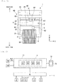
- Component mounting machine 1 performs a mounting operation of mounting a component onto board K.
- the direction from left to right in Fig. 1 in which board K is conveyed is the X-axis direction, and the direction from the bottom (front side) of the paper surface toward the top (rear side) is the Y-axis direction.
- Component mounting machine 1 is configured by assembling board conveyance device 2, multiple feeders 3, component transfer device 4, part camera 5, control device 6, and the like on base 10.
- Board conveyance device 2 includes a pair of guide rails 21,22, a pair of conveyor belts, a board clamping mechanism, and the like.
- the conveyor belts convey in board K to the work execution position by rotating along guide rails 21, 22 with board K placed on the conveyor belts.
- the board clamping mechanism pushes up board K at the work execution position to clamp and position board K.
- the board clamping mechanism releases board K. Subsequently, conveyor belts convey board K out.
- Feeders 3 are detachably installed in multiple groove-shaped slots provided in pallet member 11 on base 10.
- tape reel 39 is loaded from the front side of main body section 31.
- Predetermined supply position 32 for supplying components is set at the top portion in the rear vicinity of main body section 31.
- a carrier tape, in which components are accommodated in multiple cavities, is wound around tape reel 39.
- Feeder 3 intermittently feeds the carrier tape by a tape feeding mechanism (not shown) to set a component at supply position 32. In this way, feeder 3 sequentially supplies components.
- Feeder 3 is assigned with identification information and managed.
- the identification information is displayed with a label or the like on which a barcode is printed.
- a control section (not shown) of feeder 3 holds identification information and has a function of transmitting the identification information using communication.
- a label on which a barcode is printed is affixed to tape reel 39 and displayed.
- the identification information and the information on the type of component may be assigned by a display location and a display method other those described above.
- the width of the carrier tape are of multiple types varying in a stepwise manner depending on the size of the components.
- Feeder 3 may be of multiple types corresponding to the width of the carrier tape. Even if the width of the carrier tapes is the same, the sizes of the components may differ. In many carrier tapes, the smaller the size of the component, the higher the required positional accuracy Breq (see Fig. 8 ) required for supply position 32 when a component is picked up by suction nozzle 46 (described later).
- Component transfer device 4 is disposed above board conveyance device 2 and feeder 3. Component transfer device 4 collects components from feeder 3 and mounts the components onto board K.
- Component transfer device 4 includes head driving mechanism 40, moving base 44, mounting head 45, suction nozzle 46, mark camera 47, and the like.
- Head driving mechanism 40 is configured to include a pair of Y-axis rails 41, 42, Y-axis slider 43, and a drive motor (not shown).
- Y-axis rails 41, 42 extend parallel to each other in the Y-axis direction and are spaced apart from each other.
- Y-axis slider 43 is long in the X-axis direction, is laid across both Y-axis rails 41, 42, and moves in the Y-axis direction.
- Moving base 44 is installed on Y-axis slider 43 and moves in the X-axis direction.
- Head driving mechanism 40 drives Y-axis slider 43 in the Y-axis direction and drives moving base 44 on Y-axis slider 43 in the X-axis direction.
- Moving base 44 holds mounting head 45 and mark camera 47.
- Mounting head 45 holds one or more suction nozzles 46 on the lower side and is driven by head driving mechanism 40 to move in two horizontal directions.
- Suction nozzle 46 is operated to move up and down by being driven by lifting and lowering drive section (not shown).
- Suction nozzle 46 descends from above supply position 32 and executes a component pickup operation by supplying negative pressure.
- Suction nozzle 46 is driven to a position above board K and executes a component mounting operation by supplying a positive pressure.
- Mounting head 45 and suction nozzle 46 are of multiple types and are automatically or manually exchanged. By imaging a position mark affixed to positioned board K, mark camera 47 detects an accurate work execution position for board K.
- Part camera 5 is provided on the top face of base 10, between board conveyance device 2 and feeder 3, and faces upward. Part camera 5 captures an image of a component while suction nozzle 46 is picking up the component midway during the transit of moving base 44 from feeder 3 to board K. The acquired image data is subjected to image processing so that the pickup orientation of the component is acquired as a result of the image processing. The image processing result is reflected in the mounting operation of suction nozzle 46.
- Control device 6 is assembled to base 10, and the arrangement position of control device 6 is not particularly limited.
- Control device 6 is configured by a computer device having a CPU and operated with software.
- Control device 6 may be configured such that multiple CPUs are distributed inside.
- Control device 6 controls the mounting operation of the component in accordance with a mounting sequence stored in advance. The mounting sequence differs depending on the type of board product to be manufactured.
- control device 6 controls board conveyance device 2, feeders 3, component transfer device 4, and part camera 5.
- Management computer 71 is provided as an upper-level control device for controlling component mounting machine 1. Control device 6 of component mounting machine 1 and management computer 71 are connected to each other by wired or wireless communication. Management computer 71 transmits a command relating to the mounting operation of the board product to control device 6. Control device 6 transmits the information related to the progress of the mounting operation to management computer 71. Management computer 71 controls multiple component mounting machines 1 and other types of board work machines together.
- Management computer 71 has a database 72 for storing various data required for management. As shown in Fig. 2 and Fig. 3 , management computer 71 is communicably connected to measurement jig 75. Measurement jig 75 is a jig for measuring the supply quality of feeder 3. In the first embodiment, the supply quality is expressed with the ability of positional accuracy Bpf indicating the positional accuracy when a carrier tape is fed to set a component at predetermined supply position 32.
- measurement jig 75 When an operator installs feeder 3 in measurement jig 75 and operates the measurement start button, measurement jig 75 performs a measurement.
- measurement jig 75 includes an instruction section, a measurement calculator, and a communication section, all of which are not shown in the figure.
- the instruction section issues an instruction to the installed feeder 3 to control the feeding of the carrier tape.
- the measurement calculator measures the positional accuracy of supply position 32 after the carrier tape is fed to calculate the ability of positional accuracy Bpf.
- the measurement calculator performs, for example, measurements multiple times, averages the multiple positional accuracies, and sets the averaged positional accuracy as the ability of positional accuracy Bpf.
- the communication section acquires identification information from feeder 3, associates the identification information with the ability of positional accuracy Bpf, and transmits the information to management computer 71.
- Management computer 71 stores, in database 72, data in which identification information and ability of positional accuracy Bpf are associated with each other.
- the ability of positional accuracy Bpf may be acquired by measuring during the mounting operation which is performed upon installing feeder 3 in component mounting machine 1. That is, the image data acquired by part camera 5 includes information regarding the positional relationship between suction nozzle 46 and the component. Accordingly, by performing image processing on the image data, it is possible to obtain the ability of position accuracy Bpf. In a qualitative example, a high ability of positional accuracy Bpf is obtained when the center of the picked up component substantially coincides with the center of suction nozzle 46, whereas a low ability of positional accuracy Bpf is obtained when the centers do not coincide with each other.
- Management computer 71 also includes barcode reader 76 operated by an operator.
- Barcode reader 76 reads a barcode displayed on feeder 3 and acquires the identification information of feeder 3.
- barcode reader 76 reads a barcode displayed on the reel and acquires information on the component type.
- the information acquired by barcode reader 76 is stored in database 72. It should be noted that in a case where the display method of the identification information of feeder 3 and the information of component type is not a barcode, a device other than barcode reader 76 is used in correspondence with the display method.
- feeder determination method of the first embodiment is executed by control from feeder determination device 8 of the embodiment.
- feeder determination device 8 is achieved with software of management computer 71.
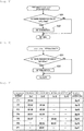
- Feeder determination device 8 includes four functional sections, that is, performance result registration section 81, performance result searching section 82, performance record-based determination section 83, and quality-based determination section 84. Each function of the four functional sections will be described with the following operational sequence.
- Feeder determination device 8 controls the execution of the operation sequence shown in Fig. 4 .
- performance result registration section 81 of feeder determination device 8 registers performance result data 73 in database 72.
- Performance result data 73 is data associating the type and size of the component used in the mounting operation that is performed in component mounting machine 1 with the identification information of feeder 3 that supplied the component.
- Performance result registration section 81 actually accumulates performance result data 73 every time component mounting machine 1 is activated.
- performance result data 73 of seven feeders 3 of identification information F1 to F7 are shown.
- Performance result data 73 not only associates the sizes of the components with the identification information of feeders 3 but also includes the supply performance records of the mounting operation.
- the supply performance record is expressed with a performance result pickup rate Apf indicating the probability that suction nozzle 46 in charge of the mounting operation succeeds in picking up a component.
- the performance result pickup rate Apf is the pickup rate, by size, for each component size.
- Data such as the number of pickup operations or the number of successful pickup operations, on which the performance result pickup rate Apf is based, the identification information of mounting head 45 or suction nozzle 46 used, and the like are included in performance result data 73.
- the size of the component is smallest in Sz1 and larger in the order of Sz2, Sz3, and Sz4.
- the performance result pickup rate Apf of the component of size Sz1 is 99.94%, and performance result data 73 of components of sizes Sz2 to Sz4 are not available. Horizontal lines are written in fields in which performance result data 73 is not stored.
- the performance result pickup rate Apf of components of size Sz1 is 99.92%
- the performance result pickup rate Apf of components of size Sz2 is 99.96%
- the performance result pickup rate Apf of components of size Sz2 is 99.81%, and performance result data 73 of components of sizes Sz1, Sz3, and Sz4 are not available.
- the ability of positional accuracies Bpf of seven feeders 3 of identification information F1 to F7 are obtained using measurement jig 75.
- the ability of positional accuracy Bpf sequentially decreases from the ability of positional accuracy Bpf1 to the ability of positional accuracy Bpf7 in accordance with the order of identification information F1 to F7 of feeder 3. That is, expressed as an inequality, Bpf1 ⁇ Bpf2 ⁇ Bpf3 ⁇ Bpf4 ⁇ Bpf5 ⁇ Bpf6 ⁇ Bpf7.
- the performance result pickup rate Apf and the ability of positional accuracy Bpf.
- the orders of the performance result pickup rate Apf and the ability of positional accuracy Bpf do not necessarily match with each other.
- feeder determination device 8 acquires information on the type of board product to be produced next.
- Feeder determination device 8 recognizes the type of a component, size of a component, number of components to be mounted per board, and the like used in the mounting operation to be performed with reference to the mounting sequence in accordance with the type of board product. For example, feeder determination device 8 recognizes six types P1 to P6 and five sizes of components shown in Fig. 8 .
- the sizes of components of type P1 and type P2 are the same Sz1.
- the size of type P3 components is Sz2
- the size of type P4 components is Sz3
- the size of type P5 components is Sz4
- the size of type P6 components is Sz5.
- the required pickup rate Areq required for favorable pickup operation of the component is set.
- the required pickup rate Areq is set to 99.90% for components of size Sz1 and size Sz2.
- the required pickup rate Areq is set to 99.85%.
- the required pickup rate Areq described above is an example, and different values may be set.
- the required pickup rate Areq is set higher as the size of the component becomes smaller.
- the required positional accuracy Breq required for favorable pickup operation of components is set.
- the required positional accuracy Breq is often set using a numerical value such as a tolerance.
- the required positional accuracy Breq is not a specific numerical value and is expressed as a relationship with the ability of positional accuracy Bpf of feeder 3.
- the required positional accuracy Breq of components of size Sz1 is set to be equal to or greater than the ability of positional accuracy Bpf3 of feeder 3 of identification information F3.
- the required positional accuracy Breq of components of sizes Sz2, Sz3 is set to be equal to or greater than the ability of positional accuracy Bpf5 of feeder 3 of identification information F5.
- the required positional accuracy Breq of components of size Sz4 is set to be equal to or greater than the ability of positional accuracy Bpf7 of feeder 3 of identification information F7.
- the required positional accuracy Breq is set higher as the size of the component becomes smaller.
- Components of type P6 have a larger size Sz5 than components of types P1 to P5, and it has been found that the pickup operation is performed satisfactorily regardless of which feeder 3 the component is combined with. Accordingly, for a large component having size Sz5 or larger, the required pickup rate Areq and the required positional accuracy Breq are not set and are excluded from the management of feeder determination device 8. Conversely, small components having sizes Sz1 to Sz4 are managed by feeder determination device 8 to determine feeder 3 to be combined.
- feeder determination device 8 lists feeders 3 that are candidates for supplying components for types P1 to P6. At this time, feeder determination device 8 excludes, from the candidates, feeders 3 that cannot be used immediately, for example, feeder 3 operating in another component mounting device or feeder 3 issued for maintenance. In the following description, a case where seven feeders 3 shown in Fig. 7 are candidates will be considered.
- feeder determination device 8 repeats the determination process from step S4 to step S14 for each component size.
- feeder determination device 8 sequentially selects from components having small sizes. This means that components are sequentially selected from components having higher required positional accuracies Breq and required pickup rates Areq.
- S5 components of type P1 and type P2 of the smallest size Sz1 are selected.
- S6 it is determined whether management of component of size Sz1 is necessary. Since management of components of size Sz1 is necessary, the execution of the operational sequence proceeds to the performance result search step, S7.
- performance result searching section 82 searches for whether candidate data obtained by combining the size of a component used for the mounting operation to be performed and the identification information of feeder 3 that is a candidate to supply the component matches any of performance result data 73 in database 72.
- candidate data obtained by combining size Sz1 of the component and identification information F1 to F7 of all feeders 3 can be considered.
- the candidate data obtained by combining size Sz1 and identification information F1 to F5 coincides with performance result data 73 (field in which the numerical value of the performance result pickup rate Apf is recorded) shown in Fig. 7 . Accordingly, the execution of the operational sequence proceeds to the performance record-based determination step S8.
- step S8 The details of the performance record-based determination step S8 are shown in Fig. 5 .
- step S21 in Fig. 5 performance record-based determination section 83 examines whether there is feeder 3 whose performance result pickup rate Apf is equal to or more than the required pickup rate Areq.
- the feeders of identification information F1 to F4 satisfy the condition that the performance result pickup rate Apf is higher than required pickup rate Areq of 99.90%. Accordingly, the execution of the operational sequence proceeds to step S22.
- the feeder of identification information F5 has a performance result pickup rate Apf of 99.87% and is lower than the required pickup rate Areq, and is excluded from the candidates.
- step S22 performance record-based determination section 83 employs a combination with feeder 3 having a higher performance result pickup rate Apf in order from the size having the higher required pickup rate Areq.
- performance record-based determination section 83 employs a combination of a component of type P1 of size Sz1 and feeder 3 of identification information F1 having the highest performance result pickup rate Apf of 99.94%.
- Performance record-based determination section 83 further employs a combination of a component of type P2 of size Sz1 and feeder 3 of identification information F2 having the second highest performance result pickup rate Apf of 99.92%.
- feeder 3 may be replaced with multiple types of components having the same size. That is, a combination of a component of type P1 and feeder 3 of identification information F2, and a combination of a component of type P2 and feeder 3 of identification information F1 may be employed. Thereafter, the execution of the operational sequence is returned to step S9 in Fig. 4 .
- step S9 it is determined whether feeders 3 for supplying components of types P1 and P2 have been determined. Since the determination has been completed as described in step S22, the execution of the operational sequence is returned to step S5.
- step S5 a component of type P3 of the second smallest size Sz2 is selected. Thereafter, the execution of the operational sequence proceeds from step S6 to the performance result search step S7.
- step S7 candidate data obtained by combining size Sz2 of the component and identification information F3 to F7 (determined identification information F1, F2 are excluded) are conceivable. Among them, candidate data obtained by combining size Sz2 and identification information F3, F4, F6, F7 coincide with performance result data 73. Accordingly, the execution of the operational sequence proceeds to the performance record-based determination step S8.
- step S21 in the second instance of performance record-based determination step S8 the feeders of identification information F3, F4 satisfy the condition that the performance result pickup rate Apf is higher than 99.90% of the required pickup rate Areq. Accordingly, the execution of the operational sequence proceeds to step S22.
- the feeders of identification information F6, F7 do not satisfy the condition and are excluded from the candidates.
- performance record-based determination section 83 compares the performance result pickup rate Apf of 99.94% of identification information F3 with the performance result pickup rate Apf of 99.95% of identification information F4 and employs a combination of feeder 3 of the higher identification information F4 and a component of type P3 of size Sz2 (see the rightmost column in Fig. 8 ). Thereafter, the execution of the operational sequence is returned to step S5 via step S9.
- step S5 a component of type P4 of the third smallest size Sz3 is selected. Thereafter, the execution of the operational sequence proceeds from step S6 to the performance result search step S7.
- step S7 candidate data obtained by combining size Sz3 of the component and identification information F3, F5 to F7 (determined identification information F1, F2, F4 are excluded) can be considered. Among them, the candidate data obtained by combining size Sz3 and identification information F5, F6 matches performance result data 73. Accordingly, the execution of the operational sequence proceeds to the performance record-based determination step S8.
- step S21 in the third instance of performance record-based determination step S8 feeders of identification information F5 and F6 have actual pickup rates Apf of 99.82% and 99.81 %, which are lower than the 99.85% of the required pickup rate Areq and do not satisfy the condition. That is, there is no feeder 3 that satisfies the ability of pickup rate Apf in order to satisfactorily perform the pickup operation. Accordingly, the execution of the operational sequence is returned to step S9 without passing through step S22. In step S9, since feeder 3 for supplying the component of type P4 is not determined, the execution of the operational sequence proceeds to the quality-based determination step S10.
- step S10 The details of the quality-based determination step S10 are shown in Fig. 6 .
- step S31 in Fig. 6 quality-based determination section 84 examines whether there is a feeder 3 having an ability of positional accuracy Bpf higher than the required position accuracy Breq.
- the feeders of identification information F6, F7 do not satisfy the condition and are excluded from the candidates.
- step S32 quality-based determination section 84 employs the combination with feeder 3 having a higher actual positional accuracy Bpf in order from the size having the higher required positional accuracy Breq.
- Quality-based determination section 84 compares the ability of position accuracy Bpf3 of identification information F3 with the ability of position accuracy Bpf5 of identification information F5 and employs a combination of feeder 3 of the higher identification information F3 and a component of type P4 of size Sz3 (see the rightmost column in Fig. 8 ). Thereafter, the execution of the operational sequence is returned to step S11.
- step S11 it is determined whether feeder 3 for supplying components of type P4 has been determined. Since the determination has been made as described in step S32, the execution of the operational sequence is returned to step S5.
- step S5 a component of type P5 having the fourth smallest size Sz4 is selected. Thereafter, the execution of the operational sequence proceeds from step S6 to the performance result search step S7.
- step S7 candidate data obtained by combining size Sz4 of the component with identification information F5 to F7 (determined identification information F1 to F4 are excluded) are considered.
- performance result data 73 of size Sz4 does not exist. Accordingly, the execution of the operational sequence is advanced to the quality-based determination step S10.
- step S32 quality-based determination section 84 employs a combination of feeder 3 of identification information F5 having the highest ability of positional accuracy Bpf5 among the three candidates and the component of type P5 of size Sz4 (see the rightmost column in Fig. 8 ). Thereafter, the execution of the operational sequence is returned to step S5 via step S11.
- step S32 feeder 3 to be combined with the component of type P5 of size Sz4 is undetermined. In this case, the execution of the operational sequence proceeds from step S11 to step S12.
- step S12 feeder determination device 8 performs a guide process. Specifically, feeder determination device 8 indicates there is no feeder 3 that satisfies the condition for satisfactorily performing the pickup operation of the component of type P5 of size Sz4. Thereafter, the execution of the operational sequence is returned to step S5.
- step S5 a component of type P6 of the largest size Sz5 is selected.
- step S6 since management of components of size Sz5 is not necessary, the execution of the operational sequence is branched to step S13.
- step S13 feeder determination device 8 determines the combination of component of type P6 of size Sz5 and remaining feeders 3 of identification information F6 or F7. Thus, the determination process of all the components is finished, and the operational sequence is finished.
- feeder determination device 8 of the first embodiment determines the combination of the size of the component and feeder 3 based on the actual pickup rate Apf of performance result data 73. Then, when the determination based on the actual pickup rate Apf cannot be performed, feeder determination device 8 performs the determination based on the ability of positional accuracy Bpf. That is, feeder determination device 8 advances the determination process on the premise that the actual pickup rate Apf is more reliable than the ability of position accuracy Bpf. As support for this premise, a case has actually occurred in which an expected actual pickup rate Apf could not be obtained even when feeder 3 having a high ability of positional accuracy Bpf was used.
- the feeder determination method and feeder determination device 8 of the first embodiment when there is performance result data 73 using sizes Sz1 to Sz5 of the components used for the mounting operation to be performed in combination with candidate feeder 3, the combination of sizes Sz1 to Sz5 of the components and feeder 3 are determined based on the supply performance record of feeder 3. Therefore, an appropriate combination is reliably determined based on the supply performance record of the highly reliable feeder 3.
- the combination is determined based on the supply quality of feeder 3. Therefore, an appropriate combination is determined based on the supply qualilty having a large correlation with supply performance records. Therefore, an appropriate feeder 3 corresponding to sizes Sz1 to Sz5 of the components is determined regardless of whether there is a performance result.
- a feeder determination method of the second embodiment will be mainly described with reference to Fig. 9 , which differs from the first embodiment.
- the high/low reliability of the pickup operation of the component is not only related to the quality of feeder 3 but also to the quality of suction nozzle 46 and mounting head 45.
- a combination of suction nozzles 46 is added to the combination of component size and feeder 3.
- Fig. 9 shows in detail a portion of the table shown in Fig. 7 .
- the actual pickup rate Apf is individually obtained for the combination of feeder 3 and multiple suction nozzles 46.
- a combination of two feeders 3 of identification information F1, F2 and three suction nozzles 46 of identification information N1 to N3 is exemplified.
- the actual pickup rates Apf individually obtained by suction nozzles 46 of identification information N1 to N3 are indicated as 99.97%, 99.95%, and 99.92%, respectively.
- the actual pickup rates Apf individually obtained by suction nozzles 46 of identification information N1 to N3 are indicated as 99.94%, 99.91%, and 99.93%, respectively.
- performance record-based determination section 83 employs a combination of a component of type P1 of size Sz1 and feeder 3 of identification information F1.
- performance record-based determination section 83 further adds a combination of suction nozzles 46 of identification information N1 having the highest actual pickup rate Apf (99.97%) obtained individually.
- Apf actual pickup rate
- performance record-based determination section 83 employs a combination of a component of type P2 of size Sz1 and feeder 3 of identification information F2.
- performance record-based determination section 83 adds a combination of suction nozzles 46 of identification information N3 having a high performance result pickup rate Apf (99.93%) obtained individually, excluding suction nozzles 46 of determined identification information N1.
- Apf 99.93%
- the combination of feeder 3 and suction nozzle 46 is also determined for the components of types P3 to P6. It should be noted that suction nozzle 46 may be commonly used for multiple types of components depending on conditions such as the number of suction nozzles provided on mounting head 45, the total number of component types, and the like. For example, suction nozzle 46 of identification information N1 may be commonly used for components of types P1 and P2 of size Sz1. In addition, a combination of feeder 3 and mounting head 45 with respect to a certain component may be determined by a similar determination method.
- a combination of suction nozzle 46 is added to the combination of the size of the component and feeder 3 based on the performance result pickup rate Apf individually obtained for the combination of feeder 3 and suction nozzle 46. Accordingly, an appropriate combination of feeder 3 and suction nozzle 46 related to the reliability of the pickup operation of the component is determined.
- step S5 components are selected sequentially from components having large required pickup rates Areq and large required position accuracies Breq.
- the actual pickup rate Apf by component size is used as the supply performance result (see Fig. 7 ).
- an average actual pickup rate determined regardless of the size or type of the component may be used.
- feeder determination device 8 excludes feeder 3 that cannot be used immediately from the candidates, but there may be another method. That is, feeder determination device 8 may execute the operational sequence by including feeder 3 that cannot be used immediately among the candidates. In this aspect, when determining the combination of the size or type of feeder 3 and the component, feeder determination device 8 sends out a notification to the effect that "feeder 3 cannot be used immediately".
- various applications and modifications can be made to the embodiments and the application modes.
Abstract
Description
- The present disclosure relates to a feeder determination method, for determining a feeder configured to supply a component used in a mounting operation of a component mounting machine, and a feeder determination device.
- Technology for mass-producing board products by performing a board operation on a board on which printed wiring is applied has become widespread. A typical example of a board work machine for performing board work is a component mounting machine for performing a component mounting operation. Many component mounting machines are exchangeably equipped with a feeder that supplies components using a carrier tape. If the reliability of supplying the feeder is reduced, a pickup error would occur in which a component cannot be picked up by a suction nozzle, resulting in the waste of the component and degradation in production efficiency.
Patent Document 1 discloses an example of a technology for suppressing this type of pickup error. - The feeder component-type determination method disclosed in
Patent Document 1 includes a positional accuracy measurement step and a component-type determination step. In the positional accuracy measurement step, the positional accuracy of the supply position is measured for at least a portion of the feeder. In the component-type determination step, a combination of the feeder and the component-type of the carrier tape is determined based on the positional accuracy of the feeder and at least one of the external dimension and the allowable positional accuracy of the component. With such a configuration, it is said that the pickup error can be suppressed even for a very small component having a strict allowable positional accuracy so as to improve the production efficiency of the board product. - Patent Document 1: International Publication No.
2015/025383 - In
Patent Document 1, it is advantageous to be able to suppress pickup errors for a very small component having a strict allowable positional accuracy. However, it takes time and effort to measure the actual positional accuracy, that is, the supply quality of each feeder. Further, the state of the feeder changes as it is used and the supply quality changes accordingly. Accordingly, it is difficult to accurately manage the present supply quality of multiple feeders, and therefore management takes a great deal of effort. Further, feeders other than new feeders have been used in the past and have a performance result of components supply. Normally, there is a strong correlation between the supply performance record obtained when the feeder is used and the supply quality of the feeder. - However, as described in
Patent Document 1, the supply quality required for a feeder generally differs depending on the size and type of the component. For this reason, it is difficult to determine the appropriate feeder to match with the size and type of the component. - It is an object of the present specification to provide a feeder determination method and a feeder determination device capable of determining the appropriate feeder to match with the size or type of the component when determining a feeder to be used in a mounting operation of a component mounting machine.
- The present specification discloses a feeder determination method, comprising: a performance result registration step of registering performance result data in a database associating a size or type of a component used in a mounting operation that has been performed in a component mounting machine with identification information of a feeder that supplied the component using a carrier tape; a performance result search step of searching for whether candidate data matches any of the performance result data in the database, the candidate data being a combination of a size or type of a component used in a mounting operation to be performed; a performance record-based determination step of determining a combination of a size or type of a component and a feeder based on a supply performance record in the mounting operation that has been performed with the feeder that is to become a candidate when the candidate data matches at least one piece of the performance result data; and a quality-based determination step of determining a combination of a size or type of a component and a feeder based on a supply quality of the feeder when the candidate data does not match any of the performance result data.
- The present specification also discloses a feeder determination device, comprising: a performance result registration section configured to register performance result data in a database associating a size or type of a component used in a mounting operation that has been performed in a component mounting machine with identification information of a feeder that supplied the component using a carrier tape; a performance result search section configured to search for whether candidate data matches any of the performance result data in the database, the candidate data being a combination of a size or type of a component used in a mounting operation to be performed with identification information of a candidate feeder to supply the component; a performance record-based determination section configured to determine a combination of a size or type of a component and a feeder based on a supply performance record in the mounting operation that has been performed with the feeder when the candidate data matches at least one piece of the performance result data; and a quality-based determination section configured to determine a combination of a size or type of a component and a feeder based on a supply quality of the feeder when the candidate data does not match any of the performance result data.
- In the feeder determination method and the feeder determination device disclosed in the present specification, when there is a performance results in which a size or type of a component used in a mounting operation to be performed is used in combination with a candidate feeder, the combination of the size or type of the component and the feeder is determined based on the supply performance record of the feeder. Therefore, an appropriate combination is reliably determined based on the supply performance record of the highly reliable feeder.
- Further, when there is no performance result, a combination of a size or type of a component and a feeder is determined based on the supply quality of a feeder. Therefore, an appropriate combination is determined based on the supply quality having a large correlation with supply performance records. Accordingly, an appropriate feeder corresponding to the size or type of the component is determined regardless of whether there is a performance result.
-
-
Fig. 1 is a plan view schematically showing a configuration of a component mounting machine to which a feeder determination method of a first embodiment is applied. -
Fig. 2 is a block diagram showing a control configuration of the component mounting device and a management computer. -
Fig. 3 is a perspective view schematically showing a method for obtaining the supply quality of a feeder. -
Fig. 4 is an operational flowchart showing the feeder determination method of the embodiment. -
Fig. 5 is a detailed flowchart of a performance record-based determination step within the operational sequence. -
Fig. 6 is a detailed flowchart of a quality-based determination step within the operational sequence. -
Fig. 7 is a diagram showing a table of simple examples of supply performance records and supply qualities of candidate feeders. -
Fig. 8 is a table showing a method for determining the combination of component size and feeder based on the supply performance records and supply qualities exemplified inFig. 7 . -
Fig. 9 is a partial detailed view of a table showing supply performance records individually obtained for a combination of a feeder and a suction nozzle in a second embodiment. - First, a configuration example of
component mounting machine 1 to which the feeder determination method of the first embodiment is applied will be described with reference toFig. 1 .Component mounting machine 1 performs a mounting operation of mounting a component onto board K. The direction from left to right inFig. 1 in which board K is conveyed is the X-axis direction, and the direction from the bottom (front side) of the paper surface toward the top (rear side) is the Y-axis direction.Component mounting machine 1 is configured by assemblingboard conveyance device 2,multiple feeders 3,component transfer device 4,part camera 5,control device 6, and the like onbase 10. -
Board conveyance device 2 includes a pair ofguide rails guide rails -
Feeders 3 are detachably installed in multiple groove-shaped slots provided inpallet member 11 onbase 10. In eachfeeder 3,tape reel 39 is loaded from the front side ofmain body section 31.Predetermined supply position 32 for supplying components is set at the top portion in the rear vicinity ofmain body section 31. A carrier tape, in which components are accommodated in multiple cavities, is wound aroundtape reel 39.Feeder 3 intermittently feeds the carrier tape by a tape feeding mechanism (not shown) to set a component atsupply position 32. In this way, feeder 3 sequentially supplies components. -
Feeder 3 is assigned with identification information and managed. The identification information is displayed with a label or the like on which a barcode is printed. Further, a control section (not shown) offeeder 3 holds identification information and has a function of transmitting the identification information using communication. Further, as for the information on the type of component accommodated intape reel 39, a label on which a barcode is printed is affixed totape reel 39 and displayed. The identification information and the information on the type of component may be assigned by a display location and a display method other those described above. - The width of the carrier tape are of multiple types varying in a stepwise manner depending on the size of the components.
Feeder 3 may be of multiple types corresponding to the width of the carrier tape. Even if the width of the carrier tapes is the same, the sizes of the components may differ. In many carrier tapes, the smaller the size of the component, the higher the required positional accuracy Breq (seeFig. 8 ) required forsupply position 32 when a component is picked up by suction nozzle 46 (described later). -
Component transfer device 4 is disposed aboveboard conveyance device 2 andfeeder 3.Component transfer device 4 collects components fromfeeder 3 and mounts the components onto board K.Component transfer device 4 includeshead driving mechanism 40, movingbase 44, mountinghead 45,suction nozzle 46,mark camera 47, and the like.Head driving mechanism 40 is configured to include a pair of Y-axis rails axis slider 43, and a drive motor (not shown). Y-axis rails axis slider 43 is long in the X-axis direction, is laid across both Y-axis rails base 44 is installed on Y-axis slider 43 and moves in the X-axis direction.Head driving mechanism 40 drives Y-axis slider 43 in the Y-axis direction and drives movingbase 44 on Y-axis slider 43 in the X-axis direction. - Moving
base 44 holds mountinghead 45 andmark camera 47. Mountinghead 45 holds one ormore suction nozzles 46 on the lower side and is driven byhead driving mechanism 40 to move in two horizontal directions.Suction nozzle 46 is operated to move up and down by being driven by lifting and lowering drive section (not shown).Suction nozzle 46 descends fromabove supply position 32 and executes a component pickup operation by supplying negative pressure.Suction nozzle 46 is driven to a position above board K and executes a component mounting operation by supplying a positive pressure. Mountinghead 45 andsuction nozzle 46 are of multiple types and are automatically or manually exchanged. By imaging a position mark affixed to positioned board K,mark camera 47 detects an accurate work execution position for board K. -
Part camera 5 is provided on the top face ofbase 10, betweenboard conveyance device 2 andfeeder 3, and faces upward.Part camera 5 captures an image of a component whilesuction nozzle 46 is picking up the component midway during the transit of movingbase 44 fromfeeder 3 to board K. The acquired image data is subjected to image processing so that the pickup orientation of the component is acquired as a result of the image processing. The image processing result is reflected in the mounting operation ofsuction nozzle 46. -
Control device 6 is assembled tobase 10, and the arrangement position ofcontrol device 6 is not particularly limited.Control device 6 is configured by a computer device having a CPU and operated with software.Control device 6 may be configured such that multiple CPUs are distributed inside.Control device 6 controls the mounting operation of the component in accordance with a mounting sequence stored in advance. The mounting sequence differs depending on the type of board product to be manufactured. - As shown in
Fig. 2 ,control device 6 controlsboard conveyance device 2,feeders 3,component transfer device 4, andpart camera 5.Management computer 71 is provided as an upper-level control device for controllingcomponent mounting machine 1.Control device 6 ofcomponent mounting machine 1 andmanagement computer 71 are connected to each other by wired or wireless communication.Management computer 71 transmits a command relating to the mounting operation of the board product to controldevice 6.Control device 6 transmits the information related to the progress of the mounting operation tomanagement computer 71.Management computer 71 controls multiplecomponent mounting machines 1 and other types of board work machines together. -
Management computer 71 has adatabase 72 for storing various data required for management. As shown inFig. 2 andFig. 3 ,management computer 71 is communicably connected tomeasurement jig 75.Measurement jig 75 is a jig for measuring the supply quality offeeder 3. In the first embodiment, the supply quality is expressed with the ability of positional accuracy Bpf indicating the positional accuracy when a carrier tape is fed to set a component atpredetermined supply position 32. - When an operator installs
feeder 3 inmeasurement jig 75 and operates the measurement start button,measurement jig 75 performs a measurement. Specifically,measurement jig 75 includes an instruction section, a measurement calculator, and a communication section, all of which are not shown in the figure. The instruction section issues an instruction to the installedfeeder 3 to control the feeding of the carrier tape. The measurement calculator measures the positional accuracy ofsupply position 32 after the carrier tape is fed to calculate the ability of positional accuracy Bpf. The measurement calculator performs, for example, measurements multiple times, averages the multiple positional accuracies, and sets the averaged positional accuracy as the ability of positional accuracy Bpf. The communication section acquires identification information fromfeeder 3, associates the identification information with the ability of positional accuracy Bpf, and transmits the information tomanagement computer 71.Management computer 71 stores, indatabase 72, data in which identification information and ability of positional accuracy Bpf are associated with each other. - The ability of positional accuracy Bpf may be acquired by measuring during the mounting operation which is performed upon installing
feeder 3 incomponent mounting machine 1. That is, the image data acquired bypart camera 5 includes information regarding the positional relationship betweensuction nozzle 46 and the component. Accordingly, by performing image processing on the image data, it is possible to obtain the ability of position accuracy Bpf. In a qualitative example, a high ability of positional accuracy Bpf is obtained when the center of the picked up component substantially coincides with the center ofsuction nozzle 46, whereas a low ability of positional accuracy Bpf is obtained when the centers do not coincide with each other. -
Management computer 71 also includesbarcode reader 76 operated by an operator.Barcode reader 76 reads a barcode displayed onfeeder 3 and acquires the identification information offeeder 3. In addition,barcode reader 76 reads a barcode displayed on the reel and acquires information on the component type. The information acquired bybarcode reader 76 is stored indatabase 72. It should be noted that in a case where the display method of the identification information offeeder 3 and the information of component type is not a barcode, a device other thanbarcode reader 76 is used in correspondence with the display method. - Next, a feeder determination method of the first embodiment will be described using a simple example. The feeder determination method of the first embodiment is executed by control from
feeder determination device 8 of the embodiment. As shown inFig. 2 ,feeder determination device 8 is achieved with software ofmanagement computer 71.Feeder determination device 8 includes four functional sections, that is, performanceresult registration section 81, performanceresult searching section 82, performance record-baseddetermination section 83, and quality-baseddetermination section 84. Each function of the four functional sections will be described with the following operational sequence. -
Feeder determination device 8 controls the execution of the operation sequence shown inFig. 4 . In the performance result registration step S1 inFig. 4 , performanceresult registration section 81 offeeder determination device 8 registersperformance result data 73 indatabase 72.Performance result data 73 is data associating the type and size of the component used in the mounting operation that is performed incomponent mounting machine 1 with the identification information offeeder 3 that supplied the component. Performanceresult registration section 81 actually accumulatesperformance result data 73 every timecomponent mounting machine 1 is activated. - In
Fig. 7 , as a simple example,performance result data 73 of sevenfeeders 3 of identification information F1 to F7 are shown.Performance result data 73 not only associates the sizes of the components with the identification information offeeders 3 but also includes the supply performance records of the mounting operation. In the first embodiment, the supply performance record is expressed with a performance result pickup rate Apf indicating the probability that suctionnozzle 46 in charge of the mounting operation succeeds in picking up a component. The performance result pickup rate Apf is the pickup rate, by size, for each component size. Data such as the number of pickup operations or the number of successful pickup operations, on which the performance result pickup rate Apf is based, the identification information of mountinghead 45 orsuction nozzle 46 used, and the like are included inperformance result data 73. - In
Fig. 7 , the size of the component is smallest in Sz1 and larger in the order of Sz2, Sz3, and Sz4. Infeeder 3 of identification information F1, the performance result pickup rate Apf of the component of size Sz1 is 99.94%, and performance resultdata 73 of components of sizes Sz2 to Sz4 are not available. Horizontal lines are written in fields in which performance resultdata 73 is not stored. Infeeder 3 of identification information F2, the performance result pickup rate Apf of components of size Sz1 is 99.92%, the performance result pickup rate Apf of components of size Sz2 is 99.96%, and there is noperformance result data 73 for components of sizes Sz3 and Sz4. The description hereinafter, can be viewed in a similar way. Infeeder 3 of identification information F7, the performance result pickup rate Apf of components of size Sz2 is 99.81%, and performance resultdata 73 of components of sizes Sz1, Sz3, and Sz4 are not available. - Further, the ability of positional accuracies Bpf of seven
feeders 3 of identification information F1 to F7 are obtained usingmeasurement jig 75. Here, it is assumed that the ability of positional accuracy Bpf sequentially decreases from the ability of positional accuracy Bpf1 to the ability of positional accuracy Bpf7 in accordance with the order of identification information F1 to F7 offeeder 3. That is, expressed as an inequality, Bpf1□Bpf2□Bpf3□Bpf4□Bpf5□Bpf6□Bpf7. There is a large correlation between the performance result pickup rate Apf and the ability of positional accuracy Bpf. However, inmultiple feeders 3, the orders of the performance result pickup rate Apf and the ability of positional accuracy Bpf do not necessarily match with each other. - In the next step, S2,
feeder determination device 8 acquires information on the type of board product to be produced next.Feeder determination device 8 recognizes the type of a component, size of a component, number of components to be mounted per board, and the like used in the mounting operation to be performed with reference to the mounting sequence in accordance with the type of board product. For example,feeder determination device 8 recognizes six types P1 to P6 and five sizes of components shown inFig. 8 . - The sizes of components of type P1 and type P2 are the same Sz1. The size of type P3 components is Sz2, the size of type P4 components is Sz3, the size of type P5 components is Sz4, and the size of type P6 components is Sz5. For components of sizes Sz1 to Sz4, the required pickup rate Areq required for favorable pickup operation of the component is set.
- Specifically, the required pickup rate Areq is set to 99.90% for components of size Sz1 and size Sz2. For components of size Sz3 and size Sz4, the required pickup rate Areq is set to 99.85%. The required pickup rate Areq described above is an example, and different values may be set. The required pickup rate Areq is set higher as the size of the component becomes smaller.
- In addition, as for the components of sizes Sz1 to Sz4, the required positional accuracy Breq required for favorable pickup operation of components is set. The required positional accuracy Breq is often set using a numerical value such as a tolerance. The required positional accuracy Breq is not a specific numerical value and is expressed as a relationship with the ability of positional accuracy Bpf of
feeder 3. - For example, the required positional accuracy Breq of components of size Sz1 is set to be equal to or greater than the ability of positional accuracy Bpf3 of
feeder 3 of identification information F3. The required positional accuracy Breq of components of sizes Sz2, Sz3 is set to be equal to or greater than the ability of positional accuracy Bpf5 offeeder 3 of identification information F5. The required positional accuracy Breq of components of size Sz4 is set to be equal to or greater than the ability of positional accuracy Bpf7 offeeder 3 of identification information F7. The required positional accuracy Breq is set higher as the size of the component becomes smaller. - Components of type P6 have a larger size Sz5 than components of types P1 to P5, and it has been found that the pickup operation is performed satisfactorily regardless of which
feeder 3 the component is combined with. Accordingly, for a large component having size Sz5 or larger, the required pickup rate Areq and the required positional accuracy Breq are not set and are excluded from the management offeeder determination device 8. Conversely, small components having sizes Sz1 to Sz4 are managed byfeeder determination device 8 to determinefeeder 3 to be combined. - In the next step, S3,
feeder determination device 8 listsfeeders 3 that are candidates for supplying components for types P1 to P6. At this time,feeder determination device 8 excludes, from the candidates,feeders 3 that cannot be used immediately, for example,feeder 3 operating in another component mounting device orfeeder 3 issued for maintenance. In the following description, a case where sevenfeeders 3 shown inFig. 7 are candidates will be considered. - Next,
feeder determination device 8 repeats the determination process from step S4 to step S14 for each component size. In step S5,feeder determination device 8 sequentially selects from components having small sizes. This means that components are sequentially selected from components having higher required positional accuracies Breq and required pickup rates Areq. In first step, S5, components of type P1 and type P2 of the smallest size Sz1 are selected. In the next step, S6, it is determined whether management of component of size Sz1 is necessary. Since management of components of size Sz1 is necessary, the execution of the operational sequence proceeds to the performance result search step, S7. - In the performance result search step S7, performance
result searching section 82 searches for whether candidate data obtained by combining the size of a component used for the mounting operation to be performed and the identification information offeeder 3 that is a candidate to supply the component matches any ofperformance result data 73 indatabase 72. In the first performance result search step S7, candidate data obtained by combining size Sz1 of the component and identification information F1 to F7 of allfeeders 3 can be considered. Among them, the candidate data obtained by combining size Sz1 and identification information F1 to F5 coincides with performance result data 73 (field in which the numerical value of the performance result pickup rate Apf is recorded) shown inFig. 7 . Accordingly, the execution of the operational sequence proceeds to the performance record-based determination step S8. - The details of the performance record-based determination step S8 are shown in
Fig. 5 . In step S21 inFig. 5 , performance record-baseddetermination section 83 examines whether there isfeeder 3 whose performance result pickup rate Apf is equal to or more than the required pickup rate Areq. In the first step, S21, the feeders of identification information F1 to F4 satisfy the condition that the performance result pickup rate Apf is higher than required pickup rate Areq of 99.90%. Accordingly, the execution of the operational sequence proceeds to step S22. It should be noted that the feeder of identification information F5 has a performance result pickup rate Apf of 99.87% and is lower than the required pickup rate Areq, and is excluded from the candidates. - In step S22, performance record-based
determination section 83 employs a combination withfeeder 3 having a higher performance result pickup rate Apf in order from the size having the higher required pickup rate Areq. In the first instance of step S22, performance record-baseddetermination section 83 employs a combination of a component of type P1 of size Sz1 andfeeder 3 of identification information F1 having the highest performance result pickup rate Apf of 99.94%. Performance record-baseddetermination section 83 further employs a combination of a component of type P2 of size Sz1 andfeeder 3 of identification information F2 having the second highest performance result pickup rate Apf of 99.92%. - The above-described employment result is shown in the rightmost column of the table in
Fig. 8 . It should be noted thatfeeder 3 may be replaced with multiple types of components having the same size. That is, a combination of a component of type P1 andfeeder 3 of identification information F2, and a combination of a component of type P2 andfeeder 3 of identification information F1 may be employed. Thereafter, the execution of the operational sequence is returned to step S9 inFig. 4 . - In step S9, it is determined whether
feeders 3 for supplying components of types P1 and P2 have been determined. Since the determination has been completed as described in step S22, the execution of the operational sequence is returned to step S5. - In the second instance of step S5, a component of type P3 of the second smallest size Sz2 is selected. Thereafter, the execution of the operational sequence proceeds from step S6 to the performance result search step S7. In the second instance of performance result search step S7, candidate data obtained by combining size Sz2 of the component and identification information F3 to F7 (determined identification information F1, F2 are excluded) are conceivable. Among them, candidate data obtained by combining size Sz2 and identification information F3, F4, F6, F7 coincide with
performance result data 73. Accordingly, the execution of the operational sequence proceeds to the performance record-based determination step S8. - In the detailed step S21 in the second instance of performance record-based determination step S8, the feeders of identification information F3, F4 satisfy the condition that the performance result pickup rate Apf is higher than 99.90% of the required pickup rate Areq. Accordingly, the execution of the operational sequence proceeds to step S22. The feeders of identification information F6, F7 do not satisfy the condition and are excluded from the candidates. In the second instance of step S22, performance record-based
determination section 83 compares the performance result pickup rate Apf of 99.94% of identification information F3 with the performance result pickup rate Apf of 99.95% of identification information F4 and employs a combination offeeder 3 of the higher identification information F4 and a component of type P3 of size Sz2 (see the rightmost column inFig. 8 ). Thereafter, the execution of the operational sequence is returned to step S5 via step S9. - In the third instance of step S5, a component of type P4 of the third smallest size Sz3 is selected. Thereafter, the execution of the operational sequence proceeds from step S6 to the performance result search step S7. In the third instance of performance result search step S7, candidate data obtained by combining size Sz3 of the component and identification information F3, F5 to F7 (determined identification information F1, F2, F4 are excluded) can be considered. Among them, the candidate data obtained by combining size Sz3 and identification information F5, F6 matches
performance result data 73. Accordingly, the execution of the operational sequence proceeds to the performance record-based determination step S8. - In detailed step S21 in the third instance of performance record-based determination step S8, feeders of identification information F5 and F6 have actual pickup rates Apf of 99.82% and 99.81 %, which are lower than the 99.85% of the required pickup rate Areq and do not satisfy the condition. That is, there is no
feeder 3 that satisfies the ability of pickup rate Apf in order to satisfactorily perform the pickup operation. Accordingly, the execution of the operational sequence is returned to step S9 without passing through step S22. In step S9, sincefeeder 3 for supplying the component of type P4 is not determined, the execution of the operational sequence proceeds to the quality-based determination step S10. - The details of the quality-based determination step S10 are shown in
Fig. 6 . In step S31 inFig. 6 , quality-baseddetermination section 84 examines whether there is afeeder 3 having an ability of positional accuracy Bpf higher than the required position accuracy Breq. The ability of position accuracy Bpf3 offeeder 3 of identification information F3 and the ability of position accuracy Bpf5 offeeder 3 of identification information F5 are equal to or greater than the required position accuracy Breq (=Bpf5 or more), and satisfy the condition. Accordingly, the execution of the operational sequence proceeds to step S32. The feeders of identification information F6, F7 do not satisfy the condition and are excluded from the candidates. - In step S32, quality-based
determination section 84 employs the combination withfeeder 3 having a higher actual positional accuracy Bpf in order from the size having the higher required positional accuracy Breq. Quality-baseddetermination section 84 compares the ability of position accuracy Bpf3 of identification information F3 with the ability of position accuracy Bpf5 of identification information F5 and employs a combination offeeder 3 of the higher identification information F3 and a component of type P4 of size Sz3 (see the rightmost column inFig. 8 ). Thereafter, the execution of the operational sequence is returned to step S11. In step S11, it is determined whetherfeeder 3 for supplying components of type P4 has been determined. Since the determination has been made as described in step S32, the execution of the operational sequence is returned to step S5. - In the fourth instance of step S5, a component of type P5 having the fourth smallest size Sz4 is selected. Thereafter, the execution of the operational sequence proceeds from step S6 to the performance result search step S7. In the fourth instance of performance result search step S7, candidate data obtained by combining size Sz4 of the component with identification information F5 to F7 (determined identification information F1 to F4 are excluded) are considered. Here,
performance result data 73 of size Sz4 does not exist. Accordingly, the execution of the operational sequence is advanced to the quality-based determination step S10. - In detailed step S31 in the quality-based determination step S10,
feeders 3 of identification information F5 to F7 have ability of positional accuracies Bpf5 to Bpf7 equal to or greater than the required positional accuracy Breq (=Bpf7 or more), and satisfies the condition. Accordingly, the execution of the operational sequence proceeds to step S32. In step S32, quality-baseddetermination section 84 employs a combination offeeder 3 of identification information F5 having the highest ability of positional accuracy Bpf5 among the three candidates and the component of type P5 of size Sz4 (see the rightmost column inFig. 8 ). Thereafter, the execution of the operational sequence is returned to step S5 via step S11. - If there is no
feeder 3 that satisfies the condition in step S32,feeder 3 to be combined with the component of type P5 of size Sz4 is undetermined. In this case, the execution of the operational sequence proceeds from step S11 to step S12. In step S12,feeder determination device 8 performs a guide process. Specifically,feeder determination device 8 indicates there is nofeeder 3 that satisfies the condition for satisfactorily performing the pickup operation of the component of type P5 of size Sz4. Thereafter, the execution of the operational sequence is returned to step S5. - In the fifth instance of step S5, a component of type P6 of the largest size Sz5 is selected. In the next step, S6, since management of components of size Sz5 is not necessary, the execution of the operational sequence is branched to step S13. In step S13,
feeder determination device 8 determines the combination of component of type P6 of size Sz5 and remainingfeeders 3 of identification information F6 or F7. Thus, the determination process of all the components is finished, and the operational sequence is finished. - If the actual pickup rate Apf of
performance result data 73 is good,feeder determination device 8 of the first embodiment determines the combination of the size of the component andfeeder 3 based on the actual pickup rate Apf ofperformance result data 73. Then, when the determination based on the actual pickup rate Apf cannot be performed,feeder determination device 8 performs the determination based on the ability of positional accuracy Bpf. That is,feeder determination device 8 advances the determination process on the premise that the actual pickup rate Apf is more reliable than the ability of position accuracy Bpf. As support for this premise, a case has actually occurred in which an expected actual pickup rate Apf could not be obtained even whenfeeder 3 having a high ability of positional accuracy Bpf was used. - In the feeder determination method and
feeder determination device 8 of the first embodiment, when there isperformance result data 73 using sizes Sz1 to Sz5 of the components used for the mounting operation to be performed in combination withcandidate feeder 3, the combination of sizes Sz1 to Sz5 of the components andfeeder 3 are determined based on the supply performance record offeeder 3. Therefore, an appropriate combination is reliably determined based on the supply performance record of the highlyreliable feeder 3. - In addition, when there is no
performance result data 73 or when there are not enough supply performance records even if there isperformance result data 73, the combination is determined based on the supply quality offeeder 3. Therefore, an appropriate combination is determined based on the supply qualilty having a large correlation with supply performance records. Therefore, anappropriate feeder 3 corresponding to sizes Sz1 to Sz5 of the components is determined regardless of whether there is a performance result. - In addition, in a case where there is
performance result data 73, since the determination process is performed using the record pickup rate Apf in the data, it is not necessary to measure the supply qualilty offeeder 3, and in addition, it is not necessary to accurately manage the present supply quality. Accordingly, a significant labor saving is achieved when determining the combination of sizes Sz1 to Sz5 of the components andfeeder 3. - Next, a feeder determination method of the second embodiment will be mainly described with reference to
Fig. 9 , which differs from the first embodiment. The high/low reliability of the pickup operation of the component is not only related to the quality offeeder 3 but also to the quality ofsuction nozzle 46 and mountinghead 45. In the second embodiment, in the performance record-based determination step S8, a combination ofsuction nozzles 46 is added to the combination of component size andfeeder 3.Fig. 9 shows in detail a portion of the table shown inFig. 7 . As shown in the figure, in the second embodiment, the actual pickup rate Apf is individually obtained for the combination offeeder 3 andmultiple suction nozzles 46. - In
Fig. 9 , a combination of twofeeders 3 of identification information F1, F2 and threesuction nozzles 46 of identification information N1 to N3 is exemplified. As a breakdown of the actual pickup rate Apf (99.94%) of the component of size Sz1 offeeder 3 of identification information F1, the actual pickup rates Apf individually obtained bysuction nozzles 46 of identification information N1 to N3 are indicated as 99.97%, 99.95%, and 99.92%, respectively. Similarly, as a breakdown of the actual pickup rate Apf (99.92%) of the component of size Sz1 offeeder 3 of identification information F2, the actual pickup rates Apf individually obtained bysuction nozzles 46 of identification information N1 to N3 are indicated as 99.94%, 99.91%, and 99.93%, respectively. - In the first step, S22, of the first embodiment, performance record-based
determination section 83 employs a combination of a component of type P1 of size Sz1 andfeeder 3 of identification information F1. In the second embodiment, performance record-baseddetermination section 83 further adds a combination ofsuction nozzles 46 of identification information N1 having the highest actual pickup rate Apf (99.97%) obtained individually. As a result, in the mounting operation ofcomponent mounting device 1,feeder 3 of identification information F1 andsuction nozzle 46 of identification information N1 are combined and used for the component of type P1 of size Sz1. - Similarly, performance record-based
determination section 83 employs a combination of a component of type P2 of size Sz1 andfeeder 3 of identification information F2. In addition, performance record-baseddetermination section 83 adds a combination ofsuction nozzles 46 of identification information N3 having a high performance result pickup rate Apf (99.93%) obtained individually, excludingsuction nozzles 46 of determined identification information N1. As a result, in the mounting operation ofcomponent mounting device 1,feeder 3 of identification information F2 andsuction nozzle 46 of identification information N3 are combined and used for the component of type P2 of size Sz1. - Although not described in detail, the combination of
feeder 3 andsuction nozzle 46 is also determined for the components of types P3 to P6. It should be noted thatsuction nozzle 46 may be commonly used for multiple types of components depending on conditions such as the number of suction nozzles provided on mountinghead 45, the total number of component types, and the like. For example,suction nozzle 46 of identification information N1 may be commonly used for components of types P1 and P2 of size Sz1. In addition, a combination offeeder 3 and mountinghead 45 with respect to a certain component may be determined by a similar determination method. - In the feeder determination method of the second embodiment, in the performance record-based determination step S8, a combination of
suction nozzle 46 is added to the combination of the size of the component andfeeder 3 based on the performance result pickup rate Apf individually obtained for the combination offeeder 3 andsuction nozzle 46. Accordingly, an appropriate combination offeeder 3 andsuction nozzle 46 related to the reliability of the pickup operation of the component is determined. - Many types of components and combinations of
feeder 3 andsuction nozzle 46 are actually determined as compared with those described in the embodiment. In the first embodiment, even if the sizes of the components are the same, in a case where the required pickup rate Areq and the required positional accuracy Breq are different from each other for each type, steps S4 to S14 of the operational sequence shown inFig. 4 are repeated for each type of component. At this time, the performance result pickup rate Apf is preferably a pickup rate by type required for each type of component. - Further, when the order in which the sizes of the components are small does not match with the order in which the required pickup rates Areq and the required positional accuracies Breq are high, in step S5, components are selected sequentially from components having large required pickup rates Areq and large required position accuracies Breq. In the first embodiment, the actual pickup rate Apf by component size is used as the supply performance result (see
Fig. 7 ). Alternatively, an average actual pickup rate determined regardless of the size or type of the component may be used. As a result, the management ofdatabase 72 and the determination process of the operational sequence are simplified. - In addition, in step S3 of
Fig. 4 ,feeder determination device 8 excludesfeeder 3 that cannot be used immediately from the candidates, but there may be another method. That is,feeder determination device 8 may execute the operational sequence by includingfeeder 3 that cannot be used immediately among the candidates. In this aspect, when determining the combination of the size or type offeeder 3 and the component,feeder determination device 8 sends out a notification to the effect that "feeder 3 cannot be used immediately". In addition, various applications and modifications can be made to the embodiments and the application modes. - 1: Component mounting device, 3: Feeder, 32: Supply position, 6: Control device, 71: Management computer, 73: Performance result data, 75: Measurement jig, 8: Feeder determination device, 81: Performance result registration section, 82: Performance result search section, 83: Performance record-based determination section, 84: Quality-based determination section, S1: Performance result registration step, S7: Performance result search step, S8: Performance record-based determination step, S10: Quality-based determination step, F1-F7: Identification information, N1-N3: Identification information, P1-P6: Type, Sz1-Sz5: Size, Apf: Performance result pickup rate, Areq: Required pickup rate, Bpf, Bpf 1-Bpf7: Ability of positional accuracy, Breq: Required positional accuracy
Claims (10)
- A feeder determination method, comprising:a performance result registration step of registering performance result data in a database associating a size or type of a component used in a mounting operation that has been performed in a component mounting machine with identification information of a feeder that supplied the component using a carrier tape;a performance result search step of searching for whether candidate data matches any of the performance result data in the database, the candidate data being a combination of a size or type of a component used in a mounting operation to be performed and identification information of a candicate feeder to supply the component;a performance record-based determination step of determining a combination of a size or type of a component and a feeder based on a supply performance record in the mounting operation that has been performed with the feeder that is to become a candidate when the candidate data matches at least one piece of the performance result data; anda quality-based determination step of determining a combination of a size or type of a component and a feeder based on a supply quality of the feeder when the candidate data does not match any of the performance result data.
- The feeder determination method of claim 1, whereinthe supply quality is represented by ability of positional accuracy indicating positional accuracy when the carrier tape is fed to set the component at a predetermined supply position, andthe combination with the feeder having a higher ability of positional accuracy thanthe required positional accuracy, which is the positional accuracy necessary forthe size or type of the component, is employed in the quality-based determination step.
- The feeder determination method of claim 2, wherein
the component to be mounted has a multiple of the sizes or types, and, in the quality-based determining step, the combination with the feeder having the higher ability of positional accuracy is employed sequentially from the size or type having the higher required positional accuracy. - The feeder determination method of claim 2 or 3, wherein
the ability of positional accuracy is acquired by measurement performed by installing the feeder in a measurement jig or by measurement during the mounting operation performed by installing the feeder in the component mounting machine. - The feeder determination method of any one of claims 1 to 4, wherein
the supply performance record is represented by a performance result pickup rate, which is the probability that a suction nozzle responsible for the mounting operation succeeds in picking up the component, and, in the performance record-based step, the combination with the feeder having a higher performance result pickup rate than the required pickup rate, which is a pickup rate required for the size or type of the component, is employed. - The feeder determination method of claim 5, wherein the components used for the mounting operation to be executed has a multiple of the sizes or the types, and, in the performance record-based determination step, the combination with the feeder having the higher performance result pickup rate is used in order from the size or the type having the higher required pickup rate.
- The feeder determination method of claim 5 or 6, wherein
the performance result pickup rate is individually determined for a combination of the feeder and at least one of the suction nozzle and the mounting head that holds the suction nozzle, and a combination of at least one of the suction nozzle and the mounting head is added to the combination of the size or type of the component and the feeder based on the individually determined performance result pickup rate in the performance record-based determination step. - The feeder determination method of any one of claims 5 to 7, wherein the performance result pickup rate is determined regardless of the size and type of the component or is determined for each size or type of the component.
- The feeder determination method of any one of claims 1 to 8, wherein, when a candidate feeder cannot be used immediately, the feeder is excluded from the candidates and combinations with the size or type of the component are avoided, or, when a combination with the size or type of the component is determined, notification is sent out indicating the candidate feeder cannot be used immediately.
- A feeder determination device, comprising:a performance result registration section configured to register performance result data in a database associating a size or type of a component used in a mounting operation that has been performed in a component mounting machine with identification information of a feeder that supplied the component using a carrier tape;a performance result search section configured to search for whether candidate data matches any of the performance result data in the database, the candidate data being a combination of a size or type of a component used in a mounting operation to be performed with identification information of a candidate feeder to supply the component;a performance record-based determination section configured to determine a combination of a size or type of a component and a feeder based on a supply performance record in the mounting operation that has been performed with the feeder when the candidate data matches at least one piece of the performance result data; anda quality-based determination section configured to determine a combination of a size or type of a component and a feeder based on a supply quality of the feeder when the candidate data does not match any of the performance result data.
Applications Claiming Priority (1)
| Application Number | Priority Date | Filing Date | Title |
|---|---|---|---|
| PCT/JP2019/002423 WO2020152839A1 (en) | 2019-01-25 | 2019-01-25 | Feeder determination method and feeder determination device |
Publications (3)
| Publication Number | Publication Date |
|---|---|
| EP3917302A1 true EP3917302A1 (en) | 2021-12-01 |
| EP3917302A4 EP3917302A4 (en) | 2022-01-26 |
| EP3917302B1 EP3917302B1 (en) | 2024-05-01 |
Family
ID=71736857
Family Applications (1)
| Application Number | Title | Priority Date | Filing Date |
|---|---|---|---|
| EP19911230.1A Active EP3917302B1 (en) | 2019-01-25 | 2019-01-25 | Feeder determination method and feeder determination device |
Country Status (4)
| Country | Link |
|---|---|
| EP (1) | EP3917302B1 (en) |
| JP (1) | JP7059404B2 (en) |
| CN (1) | CN113228842B (en) |
| WO (1) | WO2020152839A1 (en) |
Family Cites Families (10)
| Publication number | Priority date | Publication date | Assignee | Title |
|---|---|---|---|---|
| EP1343363A1 (en) * | 2002-03-08 | 2003-09-10 | TraceXpert A/S | Feeder verification with a camera |
| JP4813445B2 (en) * | 2007-11-14 | 2011-11-09 | ヤマハ発動機株式会社 | Component supply method, surface mounter, feeder and cart |
| CN101869011B (en) * | 2007-11-14 | 2012-08-22 | 雅马哈发动机株式会社 | Component feeding method, surface mounting machine, feeder and carriage |
| JP4813444B2 (en) * | 2007-11-14 | 2011-11-09 | ヤマハ発動機株式会社 | Component supply method, surface mounter, feeder and cart |
| JP4740282B2 (en) * | 2008-05-01 | 2011-08-03 | ヤマハ発動機株式会社 | Production program creation device, mounting system and mounting machine |
| JP5445537B2 (en) * | 2011-08-25 | 2014-03-19 | パナソニック株式会社 | Tape feeder, component mounting apparatus, and component mounting method |
| JP6067840B2 (en) * | 2013-03-29 | 2017-01-25 | 富士機械製造株式会社 | Feeder power supply control apparatus and method |
| EP3038443B1 (en) * | 2013-08-21 | 2020-10-21 | FUJI Corporation | Feeder component type determination method and feeder component type determination device |
| US10806037B2 (en) * | 2017-01-05 | 2020-10-13 | Panasonic Intellectual Property Management Co., Ltd. | Component mounting system |
| US10512201B2 (en) * | 2017-03-23 | 2019-12-17 | Panasonic Intellectual Property Management Co., Ltd. | Member preparation method and member preparation apparatus |
-
2019
- 2019-01-25 JP JP2020567327A patent/JP7059404B2/en active Active
- 2019-01-25 EP EP19911230.1A patent/EP3917302B1/en active Active
- 2019-01-25 CN CN201980085670.9A patent/CN113228842B/en active Active
- 2019-01-25 WO PCT/JP2019/002423 patent/WO2020152839A1/en unknown
Also Published As
| Publication number | Publication date |
|---|---|
| JP7059404B2 (en) | 2022-04-25 |
| JPWO2020152839A1 (en) | 2021-10-07 |
| CN113228842A (en) | 2021-08-06 |
| WO2020152839A1 (en) | 2020-07-30 |
| EP3917302B1 (en) | 2024-05-01 |
| CN113228842B (en) | 2022-09-27 |
| EP3917302A4 (en) | 2022-01-26 |
Similar Documents
| Publication | Publication Date | Title |
|---|---|---|
| US10420262B2 (en) | Feeder management device | |
| JP5767754B2 (en) | Recognition device for substrate working machine | |
| JP6367929B2 (en) | Management device | |
| US10104820B2 (en) | Mounting machine | |
| JP6204486B2 (en) | Component mounting line management device | |
| EP3267781B1 (en) | Method for optimizing allocation of component types, and device for optimizing allocation of component types | |
| US10182520B2 (en) | Mounting management device, mounting process device, mounting system, mounting management method, and mounting process method | |
| JP4887347B2 (en) | Board work system | |
| JP2012043886A (en) | Component verifying method and device | |
| JP6676482B2 (en) | Electronic component supply system | |
| EP3917302B1 (en) | Feeder determination method and feeder determination device | |
| CN109315088B (en) | Splicing unit | |
| CN111108823B (en) | Mounting accuracy measuring system and mounting accuracy measuring method for component mounting line | |
| JPWO2016203533A1 (en) | Mounting management device | |
| JP2006108138A (en) | Method of checking up component holding member | |
| JP2000022392A (en) | Electronic component layout managing apparatus for packing machine | |
| US11917765B2 (en) | Device for estimating cause of mounting error, and method for estimating cause of mounting error | |
| CN114342578B (en) | Tracking support device and tracking support method | |
| JPWO2020075257A1 (en) | Feeder conformity judgment device and feeder conformity judgment method | |
| EP3923232A1 (en) | Shape data sharing system and shape data sharing method | |
| US20220256751A1 (en) | Mounting device and method for controlling mounting device | |
| JPWO2005051066A1 (en) | Substrate support unit in backup device, method for manufacturing the same, device including the unit, and method for replacing the substrate support unit in the device | |
| KR20170080041A (en) | A method for checking feeding devices to a chip mounter |
Legal Events
| Date | Code | Title | Description |
|---|---|---|---|
| STAA | Information on the status of an ep patent application or granted ep patent |
Free format text: STATUS: THE INTERNATIONAL PUBLICATION HAS BEEN MADE |
|
| PUAI | Public reference made under article 153(3) epc to a published international application that has entered the european phase |
Free format text: ORIGINAL CODE: 0009012 |
|
| STAA | Information on the status of an ep patent application or granted ep patent |
Free format text: STATUS: REQUEST FOR EXAMINATION WAS MADE |
|
| 17P | Request for examination filed |
Effective date: 20210709 |
|
| AK | Designated contracting states |
Kind code of ref document: A1 Designated state(s): AL AT BE BG CH CY CZ DE DK EE ES FI FR GB GR HR HU IE IS IT LI LT LU LV MC MK MT NL NO PL PT RO RS SE SI SK SM TR |
|
| REG | Reference to a national code |
Ref country code: DE Ref legal event code: R079 Free format text: PREVIOUS MAIN CLASS: H05K0013020000 Ipc: H05K0013080000 Ref country code: DE Ref legal event code: R079 Ref document number: 602019051728 Country of ref document: DE Free format text: PREVIOUS MAIN CLASS: H05K0013020000 Ipc: H05K0013080000 |
|
| A4 | Supplementary search report drawn up and despatched |
Effective date: 20220107 |
|
| RIC1 | Information provided on ipc code assigned before grant |
Ipc: H05K 13/04 20060101ALI20211223BHEP Ipc: H05K 13/08 20060101AFI20211223BHEP |
|
| DAV | Request for validation of the european patent (deleted) | ||
| DAX | Request for extension of the european patent (deleted) | ||
| P01 | Opt-out of the competence of the unified patent court (upc) registered |
Effective date: 20230328 |
|
| GRAP | Despatch of communication of intention to grant a patent |
Free format text: ORIGINAL CODE: EPIDOSNIGR1 |
|
| STAA | Information on the status of an ep patent application or granted ep patent |
Free format text: STATUS: GRANT OF PATENT IS INTENDED |
|
| INTG | Intention to grant announced |
Effective date: 20240108 |
|
| GRAS | Grant fee paid |
Free format text: ORIGINAL CODE: EPIDOSNIGR3 |
|
| GRAA | (expected) grant |
Free format text: ORIGINAL CODE: 0009210 |
|
| STAA | Information on the status of an ep patent application or granted ep patent |
Free format text: STATUS: THE PATENT HAS BEEN GRANTED |