EP3914865B1 - Nachrüstbare steuerung eines abluftgebläses - Google Patents
Nachrüstbare steuerung eines abluftgebläses Download PDFInfo
- Publication number
- EP3914865B1 EP3914865B1 EP20744561.0A EP20744561A EP3914865B1 EP 3914865 B1 EP3914865 B1 EP 3914865B1 EP 20744561 A EP20744561 A EP 20744561A EP 3914865 B1 EP3914865 B1 EP 3914865B1
- Authority
- EP
- European Patent Office
- Prior art keywords
- exhaust air
- controller
- protective housing
- air blower
- sensor
- Prior art date
- Legal status (The legal status is an assumption and is not a legal conclusion. Google has not performed a legal analysis and makes no representation as to the accuracy of the status listed.)
- Active
Links
Images

Classifications
-
- F—MECHANICAL ENGINEERING; LIGHTING; HEATING; WEAPONS; BLASTING
- F24—HEATING; RANGES; VENTILATING
- F24F—AIR-CONDITIONING; AIR-HUMIDIFICATION; VENTILATION; USE OF AIR CURRENTS FOR SCREENING
- F24F7/00—Ventilation
- F24F7/007—Ventilation with forced flow
-
- F—MECHANICAL ENGINEERING; LIGHTING; HEATING; WEAPONS; BLASTING
- F24—HEATING; RANGES; VENTILATING
- F24F—AIR-CONDITIONING; AIR-HUMIDIFICATION; VENTILATION; USE OF AIR CURRENTS FOR SCREENING
- F24F11/00—Control or safety arrangements
- F24F11/62—Control or safety arrangements characterised by the type of control or by internal processing, e.g. using fuzzy logic, adaptive control or estimation of values
- F24F11/63—Electronic processing
-
- F—MECHANICAL ENGINEERING; LIGHTING; HEATING; WEAPONS; BLASTING
- F24—HEATING; RANGES; VENTILATING
- F24F—AIR-CONDITIONING; AIR-HUMIDIFICATION; VENTILATION; USE OF AIR CURRENTS FOR SCREENING
- F24F11/00—Control or safety arrangements
- F24F11/70—Control systems characterised by their outputs; Constructional details thereof
- F24F11/72—Control systems characterised by their outputs; Constructional details thereof for controlling the supply of treated air, e.g. its pressure
- F24F11/74—Control systems characterised by their outputs; Constructional details thereof for controlling the supply of treated air, e.g. its pressure for controlling air flow rate or air velocity
- F24F11/77—Control systems characterised by their outputs; Constructional details thereof for controlling the supply of treated air, e.g. its pressure for controlling air flow rate or air velocity by controlling the speed of ventilators
-
- F—MECHANICAL ENGINEERING; LIGHTING; HEATING; WEAPONS; BLASTING
- F24—HEATING; RANGES; VENTILATING
- F24F—AIR-CONDITIONING; AIR-HUMIDIFICATION; VENTILATION; USE OF AIR CURRENTS FOR SCREENING
- F24F11/00—Control or safety arrangements
- F24F11/89—Arrangement or mounting of control or safety devices
-
- F—MECHANICAL ENGINEERING; LIGHTING; HEATING; WEAPONS; BLASTING
- F24—HEATING; RANGES; VENTILATING
- F24F—AIR-CONDITIONING; AIR-HUMIDIFICATION; VENTILATION; USE OF AIR CURRENTS FOR SCREENING
- F24F13/00—Details common to, or for air-conditioning, air-humidification, ventilation or use of air currents for screening
- F24F13/08—Air-flow control members, e.g. louvres, grilles, flaps or guide plates
- F24F13/082—Grilles, registers or guards
- F24F13/084—Grilles, registers or guards with mounting arrangements, e.g. snap fasteners for mounting to the wall or duct
-
- F—MECHANICAL ENGINEERING; LIGHTING; HEATING; WEAPONS; BLASTING
- F24—HEATING; RANGES; VENTILATING
- F24F—AIR-CONDITIONING; AIR-HUMIDIFICATION; VENTILATION; USE OF AIR CURRENTS FOR SCREENING
- F24F13/00—Details common to, or for air-conditioning, air-humidification, ventilation or use of air currents for screening
- F24F13/20—Casings or covers
-
- F—MECHANICAL ENGINEERING; LIGHTING; HEATING; WEAPONS; BLASTING
- F24—HEATING; RANGES; VENTILATING
- F24F—AIR-CONDITIONING; AIR-HUMIDIFICATION; VENTILATION; USE OF AIR CURRENTS FOR SCREENING
- F24F7/00—Ventilation
- F24F7/02—Roof ventilation
- F24F7/025—Roof ventilation with forced air circulation by means of a built-in ventilator
-
- F—MECHANICAL ENGINEERING; LIGHTING; HEATING; WEAPONS; BLASTING
- F24—HEATING; RANGES; VENTILATING
- F24F—AIR-CONDITIONING; AIR-HUMIDIFICATION; VENTILATION; USE OF AIR CURRENTS FOR SCREENING
- F24F13/00—Details common to, or for air-conditioning, air-humidification, ventilation or use of air currents for screening
- F24F13/20—Casings or covers
- F24F2013/207—Casings or covers with control knobs; Mounting controlling members or control units therein
-
- F—MECHANICAL ENGINEERING; LIGHTING; HEATING; WEAPONS; BLASTING
- F24—HEATING; RANGES; VENTILATING
- F24F—AIR-CONDITIONING; AIR-HUMIDIFICATION; VENTILATION; USE OF AIR CURRENTS FOR SCREENING
- F24F2110/00—Control inputs relating to air properties
- F24F2110/10—Temperature
-
- F—MECHANICAL ENGINEERING; LIGHTING; HEATING; WEAPONS; BLASTING
- F24—HEATING; RANGES; VENTILATING
- F24F—AIR-CONDITIONING; AIR-HUMIDIFICATION; VENTILATION; USE OF AIR CURRENTS FOR SCREENING
- F24F2110/00—Control inputs relating to air properties
- F24F2110/20—Humidity
-
- F—MECHANICAL ENGINEERING; LIGHTING; HEATING; WEAPONS; BLASTING
- F24—HEATING; RANGES; VENTILATING
- F24F—AIR-CONDITIONING; AIR-HUMIDIFICATION; VENTILATION; USE OF AIR CURRENTS FOR SCREENING
- F24F2110/00—Control inputs relating to air properties
- F24F2110/50—Air quality properties
-
- F—MECHANICAL ENGINEERING; LIGHTING; HEATING; WEAPONS; BLASTING
- F24—HEATING; RANGES; VENTILATING
- F24F—AIR-CONDITIONING; AIR-HUMIDIFICATION; VENTILATION; USE OF AIR CURRENTS FOR SCREENING
- F24F2221/00—Details or features not otherwise provided for
- F24F2221/52—Weather protecting means, e.g. against wind, rain or snow
-
- Y—GENERAL TAGGING OF NEW TECHNOLOGICAL DEVELOPMENTS; GENERAL TAGGING OF CROSS-SECTIONAL TECHNOLOGIES SPANNING OVER SEVERAL SECTIONS OF THE IPC; TECHNICAL SUBJECTS COVERED BY FORMER USPC CROSS-REFERENCE ART COLLECTIONS [XRACs] AND DIGESTS
- Y02—TECHNOLOGIES OR APPLICATIONS FOR MITIGATION OR ADAPTATION AGAINST CLIMATE CHANGE
- Y02B—CLIMATE CHANGE MITIGATION TECHNOLOGIES RELATED TO BUILDINGS, e.g. HOUSING, HOUSE APPLIANCES OR RELATED END-USER APPLICATIONS
- Y02B30/00—Energy efficient heating, ventilation or air conditioning [HVAC]
- Y02B30/70—Efficient control or regulation technologies, e.g. for control of refrigerant flow, motor or heating
Definitions
- the application relates generally to a retrofittable controller for a building's exhaust air blower.
- the exhaust air blower As the exhaust air blower is removing air from apartments, the latter develop a negative pressure, it being by virtue of the negative pressure that the fresh make-up air, replacing the air that is being removed, enters the apartments either in a controlled manner by way of fresh air valves or in an uncontrolled manner through the apartment building's structures.
- the exhaust air blowers operate usually at two speeds and with timer control.
- the timer-controlled exhaust air blower is working at half or full capacity depending on the assessed utilization rate of an apartment building.
- Document FI 12 255 U1 discloses an exhaust-air blower and exhaust-air system of a building.
- Document US 2010/006661 A1 discloses an automatic exhaust fan control apparatus and method.
- One objective of the invention is to solve problems of the prior art and to provide a retrofittable exhaust air blower controller, enabling an old exhaust air blower to be converted into a smart exhaust air blower. It is by virtue of intelligence added to an exhaust air blower that the exhaust air blower enables implementation of need-adapted ventilation on the basis of measurement data indicated by sensors, thereby preventing e.g. the ventilation-induced loss of heat energy, improving the comfort of living, enhancing safety in apartments, eliminating the feeling of draft from apartments, enabling nocturnal summertime ventilations in apartments, improving fire safety and eliminating the mechanical sounds of exhaust air fans.
- One objective of the invention is attained with a retrofittable exhaust air blower controller, a control method, and a computer program product according to the independent claims.
- the controller further comprises a sensor unit, comprising at least one sensor for measuring the exhaust air arriving at the exhaust air blower, and a control unit which is adapted to regulate operation of a fan motor on the basis of a measurement conducted by at least one sensor.
- the controller further comprises a protective housing inside which the controller's units are installed, and an attachment element for fastening the controller to a safety cage of the exhaust air blower.
- the protective housing comprises an air inlet duct, which protrudes therefrom and is intended to be fitted inside the exhaust air blower's safety cage, and by means of which a portion of the exhaust air arriving at the exhaust air blower is conducted into the protective housing to be analyzed by the sensor unit.
- the control method according to one embodiment for a building's exhaust air blower is implemented with a controller according to the previous embodiment.
- the method comprises a step of measuring, with at least one sensor of a sensor unit (224), the exhaust air arriving at the exhaust air blower.
- the method further comprises a step of regulating, with a control unit, the operation of a controller-coupled fan motor of the exhaust air blower on the basis of a measurement conducted by at least one sensor.
- the computer program product according to one embodiment intended for controlling a building's exhaust air blower comprises instructions which enable a computer to execute steps of the method according to the previous embodiment as the program is run on the computer.
- Fig. 1a shows an exhaust air blower (roof extractor) 100, which is capable of being fitted in a ventilation pipe for the exhaust air duct of a building 351, e.g. an apartment building or a row house, and which is updated for smartness by retrofitting it with a controller (control unit) 126 for a fan motor 220.
- a controller control unit
- the exhaust air blower 100 is mounted on the end of an exhaust air duct extended from interior spaces of the building 351 up to its roof, whereby the removable air leaves the building 351 by way of the exhaust air blower 100.
- the exhaust air blower 100 has a safety cage (outlet diffuser) 102 with a function of protecting components 220 therein from the effect of weather and mechanical impacts.
- the safety cage 102 is fabricated from thin sheet metal whose material is e.g. aluminum and/or steel.
- the safety cage 102 comprises side members 104, a bottom plate attached to the lower part thereof and provided with a penetration hole for a ventilation pipe, and a lid 112.
- the exhaust air discharges from the safety cage by way of air vents 105 in the side members 104 as well as by way of a gap between a top edge of the side members 104 and the lid 112.
- air vents 105 in the side members 104 As shown in the figure, the exhaust air discharges from the safety cage by way of air vents 105 in the side members 104 as well as by way of a gap between a top edge of the side members 104 and the lid 112.
- Fig. 1b shows more precisely the controller 126, which is mounted e.g. on an external surface of any side member 104 of the safety cage 102 as shown in the figure.
- the controller 126 On a bottom right-hand edge of the figure, the controller 126 is shown in a view from the direction of a rear surface 162, on a top right-hand edge from the direction of a bottom 172, and on a bottom left-hand edge from the direction of the right side.
- On a top left-hand edge is shown an air inlet duct 164 in a cross-section F-F'.
- the controller 126 is provided with a protective housing 125 with a function of protecting the controller's 126 units 222, 224, 228, 230, 232, 234 from the effects of weather and dirt as well as from mechanical impacts.
- Fabrication material for the protective housing 125 comprises e.g. plastic or steel.
- the protective housing 125 comprises (includes) an attachment element 160 by means of which the controller 126 is fastened to the safety cage 102.
- the attachment element 160 is made up e.g. by edge strips 160 provided along the sides of the protective housing 125, the attachment made therethrough being used for fastening the protective housing 125 to the safety cage 102.
- the protective housing 125 comprises an air inlet duct 164, which is provided on its rear surface 162 intended to be set against the safety cage 102, and which is protruding and intended to be fitted inside the safety cage 102, and for which the safety cage 102 must be formed with a sufficiently large opening (not shown) for inserting the air inlet duct 164 into an interior of the safety cage 102.
- the air inlet duct 164 is a hollow, e.g. tubular, rectangular or polygonal passage whose bottom surface 166 comprises an air intake 168, by way of which the analysis-bound exhaust air, to be obtained (captured) from an exhaust air flow, is capable of being directed into the air inlet duct 164 and along the same into an interior of the protective housing 125.
- the protective housing 125 has a discharge outlet 170, e.g. in a bottom 172 of the protective housing, for removing the analyzed air from inside the protective housing 125.
- the air inlet duct 164 is split with a dividing element (divider) 174 in such a way that the air inlet duct 164 has its lower part, on the side of the air intake 168, making up an air inlet section 176 intended for conveying the analysis-bound exhaust air into an interior of the protective housing 125.
- the air inlet duct 164 has its upper part making up a cable section 178 for extending into an interior of the safety cage 102 at least a connection cable (control cable) 180 for controlling the fan motor 220.
- measuring tubes 182, 183 from the installed controller 126 along the cable section 178, which tubes are used e.g. in measuring a pressure difference between an inlet chamber and an inlet cone of the exhaust air blower 100 and the first of which is placed to measure an intake pressure of the inlet chamber and the second an intake pressure of the inlet cone.
- the protective housing 125 comprises an opening 184, e.g. in its bottom 172, for extending a voltage supply cable 185 for connection out of the controller 126, and e.g. from its side or, as shown in the figure, from its bottom 172 protrudes a temperature sensor 186, included in the sensor unit 224, for a measurement of outdoor temperature.
- the protective housing 125 may also have its side or bottom 172 provided with a pressure sensor, included in the sensor unit 224, for a measurement of outdoor air pressure.
- the controller 126 comprises a shielding shell 188 attachable to the safety cage 102 and mountable on top of the protective housing 125 with a function of ensuring the working ability of the controller 126 by keeping, contingent on weather conditions, the ambient air sufficiently warm or cool and sufficiently dry, as well as protecting the controller 126 covered by the shielding shell 188 from the effects of weather and dirt, and from mechanical impacts.
- Fabrication material for the shielding shell 188 comprises e.g. plastic or metal.
- the shielding shell 188 is made up by edge strips 190 provided e.g. along its sides, the attachment made therethrough being used for fastening the shielding shell 188 to the safety cage 102.
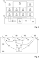
- Fig. 2 shows the functional units 220, 222, 224, 228, 230, 232, 234 of the exhaust air blower 100 and the controller 126.
- a fan motor 220 Inside the safety cage 102 of the exhaust air blower 100 is installed a fan motor 220 with a function of extracting the air to be removed from apartments into an exhaust air duct and along the same, by way of a ventilation pipe fitted in a penetration hole of the exhaust air blower 100, into an interior of the exhaust air blower 100 in which the air to be removed is blown by the fan motor 220 through the structure of the exhaust air blower 100 out of the building 351.
- the fan motor 220 is installed in the middle of a space defined by the structures of the safety cage 102.
- control unit 222 Inside the protective housing 125 of the controller 126 is installed a control unit 222, a sensor unit 224 used in assistance of control, and other functional units 228, 230, 232, 234.
- the control unit 222 is coupled with the fan motor 220 by way of a connection cable 180.
- the control unit 222 intended for managing the fan motor 220 present in the protective housing 125, has a function of its control automation to regulate the output power of the fan motor 220 in keeping with guidance received thereby.
- the sensor unit 224 housed in the protective housing 125 has at least one sensor, a measurement conducted thereby on exhaust air arriving at the exhaust air blower 100 being used as a basis for directing automation of the control unit 222 to regulate operation of the fan motor 220. At least one sensor of the sensor unit 224 can also be used for conducting measurements on outdoor air surrounding the exhaust air blower 100 and the controller 126.
- the sensor unit 224 comprises at least one of the following sensors: a temperature sensor measuring the temperature of exhaust air, a temperature sensor 186 measuring the temperature of outdoor air, a humidity sensor measuring the humidity of exhaust air, a sensor measuring the carbon dioxide content of exhaust air, a sensor measuring the VOC gas level of exhaust air, a sensor measuring the pressure of outdoor air, and sensors measuring the intake pressure of exhaust air with measuring tubes 182, 183 thereof being extended into an interior of the safety cage 102 and measuring date produced thereby also enabling the amount of air to be determined.
- the controller 126 comprises a processor unit 228, enabling instructions determined by a user or some application program to be executed and data to be processed.
- the controller 126 further comprises a data transfer unit 230, by means of which the controller 126 receives data over a wireless communication link from outside the exhaust air blower 100 (controller 126) and transmits data over a wireless connection away from the exhaust air blower 100 (controller 126).
- the data transfer unit 230 comprises e.g. a wireless 3G/4G network section, by means of which the controller 126 communicates with a device external of the exhaust air blower 100.
- the controller 126 may comprise a physical user interface unit 232, by means of which the user is able to deliver commands and information and/or to receive information.
- the user interface unit 232 is e.g. a communication interface, to which it is possible to connect by means of a connection cable e.g. an external computer, a user interface equipped with a display and keyboard, or a smart device equipped with a touchscreen.
- the controller 126 further comprises a memory unit 234 for filing and storing applications and data.
- the memory unit 234 may comprise at least one memory, e.g. one, two or three memories.
- the memory unit 234 may comprise a data transfer application 240 controlling operation of the data transfer unit 230, a user interface application 242 controlling operation of the user interface unit 232, an analyzing application 244 intended for processing data coming from the sensor unit 224, and a control application 246 intended for controlling the control unit 222 which regulates operation of the fan motor 220.
- the memory unit 234 has stored therein predetermined limit values for each quantity to be measured and, when an exceeding of limit value is indicated by measurement data coming from a sensor, the analyzing application 244 determines whether operation of the fan motor 220 is to be regulated thereby.
- the limit values determine whether the output power (rotation speed) of the fan motor 220 is continued to be maintained the same, whether it is reduced or increased.
- Limit values can be preset e.g. for temperature, such that, when the temperature of exhaust air falls to below 20°C, the control unit 222 is directed by the controller 126 to reduce output power of the fan motor 220 for reducing draft in the building's 351 apartments. On the other hand, if the temperature of exhaust air exceeds 23°C, the control unit 222 is directed by the controller 126 to increase output power of the fan motor 220 for enhancing ventilation and, if the temperature of exhaust air is with the range of 20-23°C, the current output power of the fan motor 220 will be maintained. The same applies also to other quantities to be measured. In addition, the controller 126 is capable of establishing the need of enhancing or reducing ventilation based on measurement data for two or more measured quantities on the basis of preset limit values.
- the analyzing application 244 is capable of determining a demand for ventilation on the basis of measurement data for two or more measured quantities.
- the analyzing application 244 is capable of detecting a fire in the building 351 from exhaust air by analyzing measurement data coming from VOC, carbon dioxide, temperature and humidity sensors and, based on the analysis, the controller 126 directs the control unit 222 to enhance operation of the fan motor 220 for removing smoke.
- the controller 126 is able to deliver information thereof in a wireless manner by way of the data transfer unit 230, i.e. to send a fire alarm, to some other external terminal device.
- the exhaust air blower 100 may have its operation monitored and/or controlled in real time over a wireless connection by means of a terminal device, e.g. a desk or portable computer or a smart phone, using browser-based control software intended for controlling the exhaust air blower 100.
- a terminal device e.g. a desk or portable computer or a smart phone
- browser-based control software intended for controlling the exhaust air blower 100.
- the terminal device's control software it is possible to monitor operation of the exhaust air blower 100, or several exhaust air blowers 100, by examining measurement data coming from various sensors of the controller 126 and analysis data constructed on the basis thereof, to obtain messages, e.g. a fire alarm, and to control manually operation of the exhaust air blower(s) 100.
- Fig. 3 illustrates the building's 351 exhaust air system 352, comprising several exhaust air blowers 100 as shown in the preceding figures and updated with the controller 126.
- the system 352 further comprises a distribution board 354, which is by way of power supply cables 356 in communication with each exhaust air blower 100.
- the exhaust air blowers 100 i.e., in practice, the controllers 126 thereof, communicate with each other by means of the data transfer units 230 in a wireless manner and the controller 126 (denoted with asterisk) of one exhaust air blower 100 functions as a main controller through which all other controllers 126 transmit information to an external terminal device and through which they also receive information by means of which they are controlled.
Landscapes
- Engineering & Computer Science (AREA)
- Chemical & Material Sciences (AREA)
- Combustion & Propulsion (AREA)
- Mechanical Engineering (AREA)
- General Engineering & Computer Science (AREA)
- Physics & Mathematics (AREA)
- Fluid Mechanics (AREA)
- Signal Processing (AREA)
- Fuzzy Systems (AREA)
- Mathematical Physics (AREA)
- Ventilation (AREA)
- Respiratory Apparatuses And Protective Means (AREA)
- Structures Of Non-Positive Displacement Pumps (AREA)
- Air Conditioning Control Device (AREA)
Claims (7)
- Nachrüstbare Steuerung (126) für ein Abluftgebläse (100) für ein Gebäude (351), die Folgendes umfassteine Prozessoreinheit (228),eine Datenübertragungseinheit (230),eine Speichereinheit (234),eine Sensoreinheit (224), die mindestens einen Sensor umfasst, der angepasst ist, am Abluftgebläse ankommende Abluft zu messen,eine Steuereinheit (222), die angepasst ist, auf Basis einer von dem mindestens einen Sensor vorgenommenen Messung einen Betrieb eines Lüftermotors (220) zu regeln,ein Schutzgehäuse (125), in dem die Einheiten (224, 222, 228, 230, 234) der Steuerung installiert sind, undein Befestigungselement (160), das angepasst ist, die Steuerung an einem Schutzkäfig (102) des Abluftgebläses zu fixieren,dadurch gekennzeichnet, dassdas Schutzgehäuse einen Lufteinlasskanal (164) umfasst, der davon vorsteht und dazu ausgelegt ist, durch eine Öffnung zum Einsetzen des Lufteinlasskanals (164) in einen Innenraum des Schutzkäfigs (102), die am Schutzkäfig (102) ausgebildet ist, in den Schutzkäfig (102) des Abluftgebläses eingesetzt zu werden, und durch den ein Abschnitt der Abluft, der am Abluftgebläse ankommt, in das Schutzgehäuse eingeleitet wird, um von der Sensoreinheit analysiert zu werden.
- Steuerung (126) nach dem vorhergehenden Anspruch, bei der eine Bodenfläche (166) ihres Lufteinlasskanals (164) mit einem Lufteinlass (168) zum Leiten der zu analysierenden Abluft entlang des Lufteinlasskanals in einen Innenraum des Schutzgehäuses (125) versehen ist, und das Schutzgehäuse (125) ist mit einem Austragsauslass (170) versehen, der zum Entfernen der analysierten Luft aus dem Schutzgehäuse angepasst ist.
- Steuerung (126) nach einem der vorhergehenden Ansprüche, deren Lufteinlasskanal (164) durch ein Teilungselement (174) aufgeteilt ist, um einen Lufteinlassbereich (176), der zum Befördern der zu analysierenden Abluft in einen Innenraum des Schutzgehäuses (125) ausgelegt ist, und einen Kabelbereich (178) zu erstellen, der dazu ausgelegt ist, die Messrohre (182, 183) von mindestens einem Sensor und ein Verbindungskabel (180) zum Steuern des Lüftermotors (220) in einen Innenraum des Schutzkäfigs (102) zu erstrecken.
- Steuerung (126) nach einem der vorhergehenden Ansprüche, wobei das Befestigungselement (160) aus Kantenstreifen (160) besteht, die am Schutzgehäuse (125) vorgesehen sind, wobei die damit vorgenommene Befestigung dazu ausgelegt ist, zum Fixieren des Schutzgehäuses am Schutzkäfig (102) verwendet zu werden.
- Steuerung (126) nach einem der vorhergehenden Ansprüche, die eine Abschirmhülle (188), die am Schutzkäfig (102) befestigbar und oben auf dem Schutzgehäuse (125) montierbar ist und die mindestens eine einstellbare Entlüftungsklappe umfasst, die zum Entfernen aus der Abschirmhülle der Luft, die zwischen dem Schutzgehäuse und der Abschirmhülle strömt, ausgelegt ist, Kantenstreifen (190), die zum Fixieren der Abschirmhülle am Sicherheitskäfig ausgelegt sind, und eine Überdachung (192) umfasst.
- Steuerverfahren zum Regeln eines Abluftgebläses (100) eines Gebäudes (351) mit einer nachrüstbaren Steuerung (126) nach einem der vorhergehenden Ansprüche, das Folgendes umfasstMessen der am Abluftgebläse ankommenden Abluft mit mindestens einem Sensor einer Sensoreinheit (224) undRegeln des Betriebs eines an die Steuerung gekoppelten Lüftermotors (220) des Abluftgebläses mit einer Steuereinheit (222) auf Basis einer von mindestens einem Sensor vorgenommenen Messung.
- Computerprogrammprodukt (244, 246), das Anweisungen umfasst, die es einem Computer ermöglichen, Schritte des Verfahrens nach Anspruch 6 auszuführen, wenn das Programm auf dem Computer läuft.
Applications Claiming Priority (2)
| Application Number | Priority Date | Filing Date | Title |
|---|---|---|---|
| FIU20194010U FI12406U1 (fi) | 2019-01-24 | 2019-01-24 | Jälkiasennettava rakennuksen poistoilmapuhaltimen ohjain |
| PCT/FI2020/050036 WO2020152398A1 (en) | 2019-01-24 | 2020-01-24 | Retrofittable controller of exhaust-air blower |
Publications (4)
| Publication Number | Publication Date |
|---|---|
| EP3914865A1 EP3914865A1 (de) | 2021-12-01 |
| EP3914865A4 EP3914865A4 (de) | 2022-10-19 |
| EP3914865C0 EP3914865C0 (de) | 2024-11-20 |
| EP3914865B1 true EP3914865B1 (de) | 2024-11-20 |
Family
ID=66998846
Family Applications (1)
| Application Number | Title | Priority Date | Filing Date |
|---|---|---|---|
| EP20744561.0A Active EP3914865B1 (de) | 2019-01-24 | 2020-01-24 | Nachrüstbare steuerung eines abluftgebläses |
Country Status (4)
| Country | Link |
|---|---|
| US (1) | US12259152B2 (de) |
| EP (1) | EP3914865B1 (de) |
| FI (1) | FI12406U1 (de) |
| WO (1) | WO2020152398A1 (de) |
Families Citing this family (1)
| Publication number | Priority date | Publication date | Assignee | Title |
|---|---|---|---|---|
| FI20246218A1 (en) * | 2024-10-09 | 2026-04-10 | Flaektgroup Sweden Ab | Smoke trap |
Family Cites Families (7)
| Publication number | Priority date | Publication date | Assignee | Title |
|---|---|---|---|---|
| US6935570B2 (en) | 2002-09-03 | 2005-08-30 | Phillip F. Acker | Ventilation system with humidity responsive ventilation controller |
| US7984859B2 (en) | 2008-07-14 | 2011-07-26 | Goodwin Marcus S | Automatic exhaust fan control apparatus and method |
| US20120052791A1 (en) * | 2010-08-26 | 2012-03-01 | Kurelowech Richard S | Heat recovery and demand ventiliation system |
| TW201318542A (zh) * | 2011-10-26 | 2013-05-01 | 鴻海精密工業股份有限公司 | 散熱系統 |
| US10161650B2 (en) | 2015-05-28 | 2018-12-25 | Lennox Industries Inc. | Retrofit assembly for operating a motor of an HVAC system as a multi-stage motor and an HVAC system including the retrofit assembly |
| WO2018191688A2 (en) * | 2017-04-14 | 2018-10-18 | Johnson Controls Techology Company | Thermostat with exhaust fan control for air quality and humidity control |
| FI12255U1 (fi) * | 2018-09-10 | 2018-12-14 | Entos Energiatekniikan Optimisaeaetoe Oy | Rakennuksen poistoilmapuhallin ja poistoilmajärjestelmä |
-
2019
- 2019-01-24 FI FIU20194010U patent/FI12406U1/fi active IP Right Grant
-
2020
- 2020-01-24 WO PCT/FI2020/050036 patent/WO2020152398A1/en not_active Ceased
- 2020-01-24 US US17/425,063 patent/US12259152B2/en active Active
- 2020-01-24 EP EP20744561.0A patent/EP3914865B1/de active Active
Also Published As
| Publication number | Publication date |
|---|---|
| FI12406U1 (fi) | 2019-06-14 |
| EP3914865A1 (de) | 2021-12-01 |
| EP3914865C0 (de) | 2024-11-20 |
| US20220099329A1 (en) | 2022-03-31 |
| WO2020152398A1 (en) | 2020-07-30 |
| US12259152B2 (en) | 2025-03-25 |
| EP3914865A4 (de) | 2022-10-19 |
Similar Documents
| Publication | Publication Date | Title |
|---|---|---|
| US9933182B2 (en) | System for optimising an environmental parameter of an enclosed space | |
| US20100159819A1 (en) | Duct assembly and method of using the duct assembly in an attic | |
| CN111102731B (zh) | 一种防凝露控制方法、装置及空调设备 | |
| KR101883868B1 (ko) | 온습도지수를 이용한 우사의 내부 분할형 환경관리 방법 및 장치 | |
| CN113091243B (zh) | 一种智能控制空调的控制系统及方法 | |
| EP3914865B1 (de) | Nachrüstbare steuerung eines abluftgebläses | |
| CN115371228A (zh) | 空调器及其控制方法、计算机可读存储介质 | |
| JP2020085375A (ja) | 換気装置 | |
| KR101917260B1 (ko) | 축사에 설치된 열교환 환기장치의 운전방법 | |
| CN113513804A (zh) | 空气处理设备及其控制方法、计算机可读存储介质 | |
| JP2003185207A (ja) | 建築物の換気装置 | |
| JP2009138987A (ja) | 換気装置 | |
| WO2004068038A1 (en) | Ventilation system | |
| CN110925984A (zh) | 基于机身摆叶联动下的目标人物定时避风出风方法及系统 | |
| WO2020053479A1 (en) | Exhaust-air blower and exhaust-air system of a building | |
| JP4484428B2 (ja) | 住居の換気構造 | |
| CN113513805A (zh) | 空气处理设备及其控制方法、计算机可读存储介质 | |
| US6926602B1 (en) | Crawl space ventilation system | |
| WO2022208802A1 (ja) | 空気調和システム | |
| CN209263162U (zh) | 空调风机联合运行系统 | |
| US20230053147A1 (en) | Installation frame of an exhaust blower of a building and exhaust air control system | |
| CN110925987A (zh) | 基于机身摆叶联动下的目标人物避风的出风方法及系统 | |
| CN116085925B (zh) | 空气处理设备及其控制方法、控制装置和可读存储介质 | |
| EP0856708A2 (de) | Lüftung für ein Gebäude | |
| CN204833022U (zh) | 一种智能房式粮仓 |
Legal Events
| Date | Code | Title | Description |
|---|---|---|---|
| STAA | Information on the status of an ep patent application or granted ep patent |
Free format text: STATUS: THE INTERNATIONAL PUBLICATION HAS BEEN MADE |
|
| PUAI | Public reference made under article 153(3) epc to a published international application that has entered the european phase |
Free format text: ORIGINAL CODE: 0009012 |
|
| STAA | Information on the status of an ep patent application or granted ep patent |
Free format text: STATUS: REQUEST FOR EXAMINATION WAS MADE |
|
| 17P | Request for examination filed |
Effective date: 20210806 |
|
| AK | Designated contracting states |
Kind code of ref document: A1 Designated state(s): AL AT BE BG CH CY CZ DE DK EE ES FI FR GB GR HR HU IE IS IT LI LT LU LV MC MK MT NL NO PL PT RO RS SE SI SK SM TR |
|
| DAV | Request for validation of the european patent (deleted) | ||
| DAX | Request for extension of the european patent (deleted) | ||
| A4 | Supplementary search report drawn up and despatched |
Effective date: 20220916 |
|
| RIC1 | Information provided on ipc code assigned before grant |
Ipc: F24F 7/007 20060101ALI20220912BHEP Ipc: F24F 13/20 20060101ALI20220912BHEP Ipc: F24F 11/89 20180101ALI20220912BHEP Ipc: F24F 7/02 20060101ALI20220912BHEP Ipc: F24F 7/06 20060101ALI20220912BHEP Ipc: F24F 11/77 20180101AFI20220912BHEP |
|
| GRAP | Despatch of communication of intention to grant a patent |
Free format text: ORIGINAL CODE: EPIDOSNIGR1 |
|
| STAA | Information on the status of an ep patent application or granted ep patent |
Free format text: STATUS: GRANT OF PATENT IS INTENDED |
|
| INTG | Intention to grant announced |
Effective date: 20240617 |
|
| GRAS | Grant fee paid |
Free format text: ORIGINAL CODE: EPIDOSNIGR3 |
|
| GRAA | (expected) grant |
Free format text: ORIGINAL CODE: 0009210 |
|
| STAA | Information on the status of an ep patent application or granted ep patent |
Free format text: STATUS: THE PATENT HAS BEEN GRANTED |
|
| RAP3 | Party data changed (applicant data changed or rights of an application transferred) |
Owner name: ENTOS OY |
|
| AK | Designated contracting states |
Kind code of ref document: B1 Designated state(s): AL AT BE BG CH CY CZ DE DK EE ES FI FR GB GR HR HU IE IS IT LI LT LU LV MC MK MT NL NO PL PT RO RS SE SI SK SM TR |
|
| REG | Reference to a national code |
Ref country code: GB Ref legal event code: FG4D |
|
| REG | Reference to a national code |
Ref country code: CH Ref legal event code: EP |
|
| REG | Reference to a national code |
Ref country code: DE Ref legal event code: R096 Ref document number: 602020041678 Country of ref document: DE |
|
| REG | Reference to a national code |
Ref country code: IE Ref legal event code: FG4D |
|
| U01 | Request for unitary effect filed |
Effective date: 20241220 |
|
| U07 | Unitary effect registered |
Designated state(s): AT BE BG DE DK EE FI FR IT LT LU LV MT NL PT RO SE SI Effective date: 20250110 |
|
| PG25 | Lapsed in a contracting state [announced via postgrant information from national office to epo] |
Ref country code: HR Free format text: LAPSE BECAUSE OF FAILURE TO SUBMIT A TRANSLATION OF THE DESCRIPTION OR TO PAY THE FEE WITHIN THE PRESCRIBED TIME-LIMIT Effective date: 20241120 Ref country code: IS Free format text: LAPSE BECAUSE OF FAILURE TO SUBMIT A TRANSLATION OF THE DESCRIPTION OR TO PAY THE FEE WITHIN THE PRESCRIBED TIME-LIMIT Effective date: 20250320 |
|
| PG25 | Lapsed in a contracting state [announced via postgrant information from national office to epo] |
Ref country code: ES Free format text: LAPSE BECAUSE OF FAILURE TO SUBMIT A TRANSLATION OF THE DESCRIPTION OR TO PAY THE FEE WITHIN THE PRESCRIBED TIME-LIMIT Effective date: 20241120 |
|
| PG25 | Lapsed in a contracting state [announced via postgrant information from national office to epo] |
Ref country code: NO Free format text: LAPSE BECAUSE OF FAILURE TO SUBMIT A TRANSLATION OF THE DESCRIPTION OR TO PAY THE FEE WITHIN THE PRESCRIBED TIME-LIMIT Effective date: 20250220 |
|
| PG25 | Lapsed in a contracting state [announced via postgrant information from national office to epo] |
Ref country code: GR Free format text: LAPSE BECAUSE OF FAILURE TO SUBMIT A TRANSLATION OF THE DESCRIPTION OR TO PAY THE FEE WITHIN THE PRESCRIBED TIME-LIMIT Effective date: 20250221 |
|
| PG25 | Lapsed in a contracting state [announced via postgrant information from national office to epo] |
Ref country code: PL Free format text: LAPSE BECAUSE OF FAILURE TO SUBMIT A TRANSLATION OF THE DESCRIPTION OR TO PAY THE FEE WITHIN THE PRESCRIBED TIME-LIMIT Effective date: 20241120 |
|
| PG25 | Lapsed in a contracting state [announced via postgrant information from national office to epo] |
Ref country code: RS Free format text: LAPSE BECAUSE OF FAILURE TO SUBMIT A TRANSLATION OF THE DESCRIPTION OR TO PAY THE FEE WITHIN THE PRESCRIBED TIME-LIMIT Effective date: 20250220 |
|
| U20 | Renewal fee for the european patent with unitary effect paid |
Year of fee payment: 6 Effective date: 20250407 |
|
| PG25 | Lapsed in a contracting state [announced via postgrant information from national office to epo] |
Ref country code: SM Free format text: LAPSE BECAUSE OF FAILURE TO SUBMIT A TRANSLATION OF THE DESCRIPTION OR TO PAY THE FEE WITHIN THE PRESCRIBED TIME-LIMIT Effective date: 20241120 |
|
| PG25 | Lapsed in a contracting state [announced via postgrant information from national office to epo] |
Ref country code: SK Free format text: LAPSE BECAUSE OF FAILURE TO SUBMIT A TRANSLATION OF THE DESCRIPTION OR TO PAY THE FEE WITHIN THE PRESCRIBED TIME-LIMIT Effective date: 20241120 |
|
| PG25 | Lapsed in a contracting state [announced via postgrant information from national office to epo] |
Ref country code: CZ Free format text: LAPSE BECAUSE OF FAILURE TO SUBMIT A TRANSLATION OF THE DESCRIPTION OR TO PAY THE FEE WITHIN THE PRESCRIBED TIME-LIMIT Effective date: 20241120 |
|
| REG | Reference to a national code |
Ref country code: CH Ref legal event code: PL |
|
| PG25 | Lapsed in a contracting state [announced via postgrant information from national office to epo] |
Ref country code: MC Free format text: LAPSE BECAUSE OF FAILURE TO SUBMIT A TRANSLATION OF THE DESCRIPTION OR TO PAY THE FEE WITHIN THE PRESCRIBED TIME-LIMIT Effective date: 20241120 |
|
| PLBE | No opposition filed within time limit |
Free format text: ORIGINAL CODE: 0009261 |
|
| STAA | Information on the status of an ep patent application or granted ep patent |
Free format text: STATUS: NO OPPOSITION FILED WITHIN TIME LIMIT |
|
| PG25 | Lapsed in a contracting state [announced via postgrant information from national office to epo] |
Ref country code: CH Free format text: LAPSE BECAUSE OF NON-PAYMENT OF DUE FEES Effective date: 20250131 |
|
| 26N | No opposition filed |
Effective date: 20250821 |
|
| GBPC | Gb: european patent ceased through non-payment of renewal fee |
Effective date: 20250220 |
|
| PG25 | Lapsed in a contracting state [announced via postgrant information from national office to epo] |
Ref country code: GB Free format text: LAPSE BECAUSE OF NON-PAYMENT OF DUE FEES Effective date: 20250220 |
|
| PG25 | Lapsed in a contracting state [announced via postgrant information from national office to epo] |
Ref country code: IE Free format text: LAPSE BECAUSE OF NON-PAYMENT OF DUE FEES Effective date: 20250124 |