EP3914534B1 - Diffuser for a pressurized container - Google Patents
Diffuser for a pressurized container Download PDFInfo
- Publication number
- EP3914534B1 EP3914534B1 EP20701453.1A EP20701453A EP3914534B1 EP 3914534 B1 EP3914534 B1 EP 3914534B1 EP 20701453 A EP20701453 A EP 20701453A EP 3914534 B1 EP3914534 B1 EP 3914534B1
- Authority
- EP
- European Patent Office
- Prior art keywords
- base body
- outlet conduit
- fastening
- section
- tenon
- Prior art date
- Legal status (The legal status is an assumption and is not a legal conclusion. Google has not performed a legal analysis and makes no representation as to the accuracy of the status listed.)
- Active
Links
- 239000000463 material Substances 0.000 claims description 54
- -1 polyethylene Polymers 0.000 claims description 24
- 239000000203 mixture Substances 0.000 claims description 15
- 239000004698 Polyethylene Substances 0.000 claims description 12
- 239000004743 Polypropylene Substances 0.000 claims description 12
- 230000000295 complement effect Effects 0.000 claims description 12
- 229920000573 polyethylene Polymers 0.000 claims description 12
- 229920001155 polypropylene Polymers 0.000 claims description 12
- 239000004952 Polyamide Substances 0.000 claims description 7
- 229920002647 polyamide Polymers 0.000 claims description 7
- 229930040373 Paraformaldehyde Natural products 0.000 claims description 6
- 229910052751 metal Inorganic materials 0.000 claims description 6
- 239000002184 metal Substances 0.000 claims description 6
- 229920001707 polybutylene terephthalate Polymers 0.000 claims description 6
- 229920006324 polyoxymethylene Polymers 0.000 claims description 6
- 239000000443 aerosol Substances 0.000 claims description 5
- 235000013305 food Nutrition 0.000 claims description 5
- 229910052782 aluminium Inorganic materials 0.000 claims description 4
- XAGFODPZIPBFFR-UHFFFAOYSA-N aluminium Chemical compound [Al] XAGFODPZIPBFFR-UHFFFAOYSA-N 0.000 claims description 4
- 239000002537 cosmetic Substances 0.000 claims description 4
- 239000002861 polymer material Substances 0.000 claims description 4
- 239000004753 textile Substances 0.000 claims description 4
- 229910000831 Steel Inorganic materials 0.000 claims description 3
- 239000012620 biological material Substances 0.000 claims description 3
- 239000003086 colorant Substances 0.000 claims description 3
- 239000011521 glass Substances 0.000 claims description 3
- 229910052500 inorganic mineral Inorganic materials 0.000 claims description 3
- 229920005610 lignin Polymers 0.000 claims description 3
- 239000011707 mineral Substances 0.000 claims description 3
- 239000012764 mineral filler Substances 0.000 claims description 3
- 239000005014 poly(hydroxyalkanoate) Substances 0.000 claims description 3
- 229920000903 polyhydroxyalkanoate Polymers 0.000 claims description 3
- 229920000642 polymer Polymers 0.000 claims description 3
- 229910001220 stainless steel Inorganic materials 0.000 claims description 3
- 239000010935 stainless steel Substances 0.000 claims description 3
- 239000010959 steel Substances 0.000 claims description 3
- 239000002023 wood Substances 0.000 claims description 3
- 239000004626 polylactic acid Substances 0.000 claims description 2
- 235000013311 vegetables Nutrition 0.000 claims description 2
- 229920002961 polybutylene succinate Polymers 0.000 claims 2
- 239000004631 polybutylene succinate Substances 0.000 claims 2
- 230000000994 depressogenic effect Effects 0.000 claims 1
- 210000003666 myelinated nerve fiber Anatomy 0.000 claims 1
- 239000000047 product Substances 0.000 description 14
- 208000031968 Cadaver Diseases 0.000 description 10
- 239000000243 solution Substances 0.000 description 3
- 230000000903 blocking effect Effects 0.000 description 2
- 239000006071 cream Substances 0.000 description 2
- 239000000835 fiber Substances 0.000 description 2
- 239000006260 foam Substances 0.000 description 2
- 238000009434 installation Methods 0.000 description 2
- 150000002739 metals Chemical class 0.000 description 2
- 230000002787 reinforcement Effects 0.000 description 2
- PEDCQBHIVMGVHV-UHFFFAOYSA-N Glycerine Chemical compound OCC(O)CO PEDCQBHIVMGVHV-UHFFFAOYSA-N 0.000 description 1
- 241001639412 Verres Species 0.000 description 1
- 239000004411 aluminium Substances 0.000 description 1
- 239000012141 concentrate Substances 0.000 description 1
- 239000000470 constituent Substances 0.000 description 1
- 230000000694 effects Effects 0.000 description 1
- 230000002349 favourable effect Effects 0.000 description 1
- 239000007789 gas Substances 0.000 description 1
- 239000000499 gel Substances 0.000 description 1
- 239000003292 glue Substances 0.000 description 1
- 238000002347 injection Methods 0.000 description 1
- 239000007924 injection Substances 0.000 description 1
- 239000012263 liquid product Substances 0.000 description 1
- 229940127554 medical product Drugs 0.000 description 1
- 235000011837 pasties Nutrition 0.000 description 1
- 230000000149 penetrating effect Effects 0.000 description 1
- 239000003208 petroleum Substances 0.000 description 1
- 229940127557 pharmaceutical product Drugs 0.000 description 1
- 230000000717 retained effect Effects 0.000 description 1
- 239000007921 spray Substances 0.000 description 1
- 238000003466 welding Methods 0.000 description 1
Images


Classifications
-
- B—PERFORMING OPERATIONS; TRANSPORTING
- B65—CONVEYING; PACKING; STORING; HANDLING THIN OR FILAMENTARY MATERIAL
- B65D—CONTAINERS FOR STORAGE OR TRANSPORT OF ARTICLES OR MATERIALS, e.g. BAGS, BARRELS, BOTTLES, BOXES, CANS, CARTONS, CRATES, DRUMS, JARS, TANKS, HOPPERS, FORWARDING CONTAINERS; ACCESSORIES, CLOSURES, OR FITTINGS THEREFOR; PACKAGING ELEMENTS; PACKAGES
- B65D83/00—Containers or packages with special means for dispensing contents
- B65D83/14—Containers or packages with special means for dispensing contents for delivery of liquid or semi-liquid contents by internal gaseous pressure, i.e. aerosol containers comprising propellant for a product delivered by a propellant
- B65D83/16—Containers or packages with special means for dispensing contents for delivery of liquid or semi-liquid contents by internal gaseous pressure, i.e. aerosol containers comprising propellant for a product delivered by a propellant characterised by the actuating means
- B65D83/20—Containers or packages with special means for dispensing contents for delivery of liquid or semi-liquid contents by internal gaseous pressure, i.e. aerosol containers comprising propellant for a product delivered by a propellant characterised by the actuating means operated by manual action, e.g. button-type actuator or actuator caps
- B65D83/205—Actuator caps, or peripheral actuator skirts, attachable to the aerosol container
- B65D83/206—Actuator caps, or peripheral actuator skirts, attachable to the aerosol container comprising a cantilevered actuator element, e.g. a lever pivoting about a living hinge
-
- B—PERFORMING OPERATIONS; TRANSPORTING
- B65—CONVEYING; PACKING; STORING; HANDLING THIN OR FILAMENTARY MATERIAL
- B65D—CONTAINERS FOR STORAGE OR TRANSPORT OF ARTICLES OR MATERIALS, e.g. BAGS, BARRELS, BOTTLES, BOXES, CANS, CARTONS, CRATES, DRUMS, JARS, TANKS, HOPPERS, FORWARDING CONTAINERS; ACCESSORIES, CLOSURES, OR FITTINGS THEREFOR; PACKAGING ELEMENTS; PACKAGES
- B65D83/00—Containers or packages with special means for dispensing contents
- B65D83/14—Containers or packages with special means for dispensing contents for delivery of liquid or semi-liquid contents by internal gaseous pressure, i.e. aerosol containers comprising propellant for a product delivered by a propellant
- B65D83/16—Containers or packages with special means for dispensing contents for delivery of liquid or semi-liquid contents by internal gaseous pressure, i.e. aerosol containers comprising propellant for a product delivered by a propellant characterised by the actuating means
- B65D83/20—Containers or packages with special means for dispensing contents for delivery of liquid or semi-liquid contents by internal gaseous pressure, i.e. aerosol containers comprising propellant for a product delivered by a propellant characterised by the actuating means operated by manual action, e.g. button-type actuator or actuator caps
- B65D83/205—Actuator caps, or peripheral actuator skirts, attachable to the aerosol container
-
- B—PERFORMING OPERATIONS; TRANSPORTING
- B65—CONVEYING; PACKING; STORING; HANDLING THIN OR FILAMENTARY MATERIAL
- B65D—CONTAINERS FOR STORAGE OR TRANSPORT OF ARTICLES OR MATERIALS, e.g. BAGS, BARRELS, BOTTLES, BOXES, CANS, CARTONS, CRATES, DRUMS, JARS, TANKS, HOPPERS, FORWARDING CONTAINERS; ACCESSORIES, CLOSURES, OR FITTINGS THEREFOR; PACKAGING ELEMENTS; PACKAGES
- B65D83/00—Containers or packages with special means for dispensing contents
- B65D83/14—Containers or packages with special means for dispensing contents for delivery of liquid or semi-liquid contents by internal gaseous pressure, i.e. aerosol containers comprising propellant for a product delivered by a propellant
- B65D83/44—Valves specially adapted therefor; Regulating devices
- B65D83/48—Lift valves, e.g. operated by push action
-
- B—PERFORMING OPERATIONS; TRANSPORTING
- B65—CONVEYING; PACKING; STORING; HANDLING THIN OR FILAMENTARY MATERIAL
- B65D—CONTAINERS FOR STORAGE OR TRANSPORT OF ARTICLES OR MATERIALS, e.g. BAGS, BARRELS, BOTTLES, BOXES, CANS, CARTONS, CRATES, DRUMS, JARS, TANKS, HOPPERS, FORWARDING CONTAINERS; ACCESSORIES, CLOSURES, OR FITTINGS THEREFOR; PACKAGING ELEMENTS; PACKAGES
- B65D83/00—Containers or packages with special means for dispensing contents
- B65D83/14—Containers or packages with special means for dispensing contents for delivery of liquid or semi-liquid contents by internal gaseous pressure, i.e. aerosol containers comprising propellant for a product delivered by a propellant
- B65D83/28—Nozzles, nozzle fittings or accessories specially adapted therefor
-
- B—PERFORMING OPERATIONS; TRANSPORTING
- B65—CONVEYING; PACKING; STORING; HANDLING THIN OR FILAMENTARY MATERIAL
- B65D—CONTAINERS FOR STORAGE OR TRANSPORT OF ARTICLES OR MATERIALS, e.g. BAGS, BARRELS, BOTTLES, BOXES, CANS, CARTONS, CRATES, DRUMS, JARS, TANKS, HOPPERS, FORWARDING CONTAINERS; ACCESSORIES, CLOSURES, OR FITTINGS THEREFOR; PACKAGING ELEMENTS; PACKAGES
- B65D83/00—Containers or packages with special means for dispensing contents
- B65D83/14—Containers or packages with special means for dispensing contents for delivery of liquid or semi-liquid contents by internal gaseous pressure, i.e. aerosol containers comprising propellant for a product delivered by a propellant
- B65D83/75—Aerosol containers not provided for in groups B65D83/16 - B65D83/74
- B65D83/753—Aerosol containers not provided for in groups B65D83/16 - B65D83/74 characterised by details or accessories associated with outlets
Definitions
- the invention relates to a diffuser for a pressure vessel provided with a valve, according to the preamble of claim 1.
- the finger cot may be an integral part of the base body to which it is connected by a tab. It can also be a separate part which can be pressed either in a vertical translation movement, or in a tilting movement around a support.
- the outlet duct is molded either directly on the interior face of the finger cot, or on a fixing ring used to fix the diffuser on the pressure vessel.
- the outlet conduit must be made of a material compatible with the product contained in the pressure vessel. It is therefore not only the outlet conduit which is made of this material, but the entire finger cot or the entire fixing ring. The choice of material for the finger cot or the fixing ring is rather dictated by the mechanical properties that these parts must have.
- the objective of the invention is to propose a diffuser in which the choice of the material of the outlet duct and that of the base body are dictated only by the properties sought for each of them, the diffuser must also be economical to make.
- the material used for the base body and the material used for the outlet duct are of different compositions and/or different colors. It is thus possible to limit the use of a material compatible with the product contained in the pressure vessel to only the outlet conduit, a relatively small part, while the material for the base body will be chosen for its mechanical properties, its lower cost, its aesthetics, etc.
- the mechanical hooking means consist of a hooking pin placed on the outlet conduit, and a hooking hole made in the wall of the base body opening into the cavity.
- the hanging hole is a through hole.
- the hooking pin is placed on the outlet conduit and the hooking hole is made in the base body, preferably in the finger cot.
- the hooking pin may comprise a cap connected to the outlet conduit by a rod which ends opposite the cap by a shoulder.
- the hooking hole is preferably a hole passing through the wall of the base body and comprises at least a first part, called the interior part, whose greatest transverse extension is less than the greatest transverse extension of the cap of the hooking pin , the length of the rod of the tenon being chosen such that in the hooked state of the outlet conduit, the wall of the base body at the edge of the hooking hole is between the cap and the shoulder, the section cross section of the cap and the cross section of the interior part being chosen such that when hooking the outlet conduit onto the base body, the cap can be forcefully introduced into the interior part of the hooking hole without risking damage the outlet duct or the base body.
- the cap Due to its greater transverse extension, the cap can only pass through the first part of the hooking hole by force, both in the direction of hooking and in the other direction. In other words, after being hooked, the outlet duct cannot unhook itself.
- the hooking means are designed such that the entire cross section of the cap is larger than the cross section of the first part of the hooking hole.
- the interior part of the hanging hole continues with a second part, called the exterior part, the interior part opening into the cavity of the base body and the exterior part opening outside the base body, the section transversal of the external part being dimensioned to contain the cross section of the cap of the hooking tenon.
- the length of the outer part of the hooking hole is preferably substantially identical to the height of the cap so that it is flush with the outer face of the basic body.
- the outlet conduit comprises a first substantially rectilinear section and a second section, the first section starting at the first end of the outlet conduit and ending at the junction with the second section .
- the hooking pin is placed at the top of the first section, opposite the first end, or on the second section. The hooking opening is made in the finger cot.
- the anti-rotation means consist of a tight fit of the hooking pin in the hooking hole.
- the greatest transverse extension of the hooking pin, in particular of the rod of the hooking pin can be greater than the greatest transverse extension of at least part of the hooking hole, in particular of the part inside the hanging hole.
- the cross section of the rod can be greater than the cross section of the hanging hole, in particular of the lower part. In this case, the hooking pin has forced its way into the hooking hole.
- the anti-rotation means consist of an interlocking shape of the hooking pin in the hooking hole.
- the rod of the hooking pin can fit into the interior part of the hooking hole.
- the cross section of the hooking pin, in particular of the rod of the hooking pin, and the cross section of the hooking hole, in particular of the interior part of the hooking hole are not no symmetry of revolution.
- a second solution consists of producing the anti-rotation means in the form of an interlocking shape of the cap of the hooking pin in the exterior part of the hooking hole.
- the cross section of the cap of the hooking tenon and the cross section of the external part of the hooking hole are not rotationally symmetrical.
- a simple solution is to design the cross section of the shank of the hooking pin and that of the inner part of the hooking hole, or the cross section of the cap of the hooking pin and that of the outer part of the hooking hole hooking, so that they are complementary.
- it is not essential that the shapes be complementary for example we can choose a hexagonal section for the hanging hole and a triangular section for the hanging rod or the cap, the angles of the triangle then being in correspondence with every other angle of the hanging hole. More generally, it is sufficient for the cross section of the exterior part of the hooking hole to be circumscribed to the cross section of the cap.
- the anti-rotation means are constituted by two guide tabs placed in the cavity of the base body and which surround a part of the outlet conduit preventing the latter from pivoting around the hooking pin.
- the material used for the base body and the material used for the outlet duct may be of different compositions and/or different colors.
- the hooking hole is through, and the end of the hooking pin opposite the rest of the outlet conduit, in particular the cap, has a particular shape and/or color which, in the hooked state of the outlet duct, is/are visible and recognizable from outside the diffuser and constitute(s) means of identification or information for the user.
- the basic body is preferably provided with fixing means for fixing it directly or via a ferrule to a pressure vessel.
- An orifice is generally made in the wall of the base body, facing the second end of the outlet conduit and at a distance from the hanging hole.
- the orifice can be placed in a recess in the wall of the base body. This recess, considered from outside the base body, is preferably concave in shape.
- At least part of the base body and/or at least part of the outlet conduit is/are made from a recycled material, from a biodegradable material, from a compostable material or from a biomaterial, or a mixture of these.
- the outlet conduit may be made of a food grade and/or cosmetic grade and/or pharmaceutical grade and/or medical grade material. This means that the material used complies with current standards concerning materials intended to be in contact with food, cosmetic, pharmaceutical or medical products.
- the outlet conduit is made of a virgin material and the main body is made at least partly of a recycled material.
- the invention relates to a diffuser (1) for pressure containers, in particular for aerosol generators, foam generators, dispensing systems for gels, creams, pasty or liquid products. It is intended to activate the valve of the container with a view to taking at least part of the contents of the container and distributing it, for example in the form of an aerosol or foam.
- Pressure vessels generally consist of a housing fitted with a neck closed by a valve mounted on a valve cup. Sometimes the valve cup is attached to the housing via a dome. When the valve is male type, a nozzle (stem) protrudes from the valve.
- the diffuser comprises a base body (10) provided with a finger cot (11), and an outlet conduit (20) located inside the base body.
- the finger cot (11) serves as a push button to move the outlet conduit (20) towards the aerosol generator in view to activate its valve.
- the outlet conduit (20) and the base body (10) are two separate parts, the outlet conduit being configured to be fixed by hooking means to the base body.
- the diffuser has a certain rotation geometry around a main axis (A).
- the adjectives “radial” and “axial” refer to this main axis.
- this main axis (A) is aligned with the stem of the valve, or more generally with the main axis of the valve body.
- the basic body is formed of a concave wall forming a cavity. Subsequently, the terms “interior” and “exterior” respectively qualify the elements which are in or towards the cavity and those which are outside or away from the cavity.
- the outlet conduit (20) has a first end (21) configured to cooperate with the valve; For this purpose it is provided at this first end with means for cooperating with the valve. If the valve is a female type valve, the end includes a stem intended to penetrate the valve to actuate it. If the valve is of the male type, the first end (21) is flared to facilitate the introduction of the stem when mounting the diffuser on the pressure vessel.
- the second end (22) of the outlet conduit opens outwards and can be fitted with a nozzle to improve the quality of the aerosol. If the product does not exit in alignment with the valve, the outlet conduit is divided between at least a first section (23) substantially rectilinear and a second section (24) inclined relative to the first.
- the first section begins at the first end (21) and ends at the junction with the second section (24), and the second section (24) begins at the junction with the first section (23) and ends at the second end (22).
- the second section (24) can be provided on the side of the second end with a nozzle housing (241).
- the second section (24) consists of an internal conduit (242) strictly speaking composing a part of the outlet conduit and which is surrounded by a cylindrical wall (243) at least on the side of the second end (22).
- the annular space between the inner conduit (242) and the cylindrical wall (243) constitutes the nozzle housing. If the diffuser is not equipped with a nozzle, it is possible to do without the cylindrical wall (243).
- hooking means are provided, a part of which located on the outlet conduit (20) cooperates with another complementary part made in the base body ( 10).
- the means for attaching the outlet conduit are constituted by a latching pin (25) intended to latch into a latching opening of the base body constituting the complementary part of the attachment means.
- the latching pin (25) is placed at the top of the 1st section (23), opposite the first end (21). It is preferably coaxial with the axis (A), but it is not imperative.
- the latching tenon consists of a substantially cylindrical rod (251) fixed by its first end to the outlet conduit and carrying at its second end a cap (252) of larger cross section.
- the junction between the rod (251) and the rest of the outlet conduit constitutes a shoulder (253) at a distance from the cap.
- the tenon is in fact a cylinder in which an annular groove is made.
- the top of the cylinder constitutes the cap (252), the annular groove forms the rod (251) and the part of the cylinder opposite the cap plays the role of shoulder (253).
- the base body (10) consists of a concave wall. In this example, it has a general dome shape. It could also be cylindrical.
- the base body (10) is provided with a fixing ring (12) configured to fix it either directly to the pressure vessel, in particular on the housing or the valve, or by means of a ferrule, particularly in the case of ON/OFF type diffusers.
- This fixing ring is provided with fixing means such as a series of gadroons (121) distributed regularly over the entire periphery of the fixing ring. These fixing means are intended to cooperate with complementary fixing means made on the housing or the valve of the pressure vessel, or on the ferrule.
- the gadroons (121) can snap into place behind the rolled edge at the interface between the housing and the valve cup or between the housing and the dome on which the valve cup is fixed.
- Other means of fixing can be considered, such as a continuous rib, a thread for screwing, an extra thickness of material for welding, glue for bonding, etc.
- the wall of the base body is pierced with a finger cot opening (13) in which the finger cot (11) is placed.
- the finger cot is fixed to the rest of the base body by a tab (14) which serves as a hinge so that when pressure is exerted on the finger cot towards the inside of the base body (therefore towards the valve when the diffuser is mounted on the pressure vessel), the finger cot pivots around an axis passing transversely through the tongue.
- the finger cot (11) and the corresponding opening (13) are placed towards the top of the base body.
- the projection of the finger cot (11) on a plane perpendicular to the main axis (A) covers at least the projection of the first section (23) of the outlet conduit on said plane perpendicular to the main axis (A). .
- the finger cot (11) is located above at least the top of the first section (23) of the outlet conduit.
- An opening (15) is made in the wall of the base body opposite the second end (22) of the outlet conduit.
- the product taken from the pressure vessel which leaves the outlet conduit through its second end (22) passes through this orifice (15).
- This orifice is preferably oblong and extends in an axial plane so that the 2nd end (22) of the outlet conduit, when it moves during actuation of the valve, always remains facing the the orifice (15).
- the second end (22) of the outlet conduit is therefore floating relative to the base body (10) and to the orifice (15) in particular.
- a hooking hole (16) is made in the base body (10) for fixing the outlet conduit (20).
- This hole constitutes the complementary hooking means for fixing the outlet conduit (20) to the base body (10).
- the hooking hole (16) is intended to receive and retain the hooking pin (15) of the outlet conduit. It passes right through the wall of the base body. In the example presented here, it is divided into two parts: an interior part (161) located towards the inside of the base body and an exterior part (162) opening onto the exterior face of the finger cot (11).
- the interior part (161) is dimensioned to receive the rod (251) of the hooking tenon while the exterior part, which is wider, is dimensioned to receive the cap (252) of the tenon.
- the exterior part (162) and the cap are preferably dimensioned so that the top of the cap is flush with the exterior face of the finger cot (11) and is in continuity with it.
- the length of the outer part (162) of the hanging hole (measured between the junction with the inner part (161) and the outer face of the wall of the base body) is preferably substantially identical to the height (measured between the junction of the cap with the stem and the top of the cap opposite the stem) of the cap (252).
- the top of the cap (252) is not perpendicular to the stem, but slightly inclined to follow the slope of the finger cot at this location.
- the cap (252) and the interior part (161) of the hooking hole are dimensioned so that the cap can pass by force through the stem portion when mounting the outlet conduit on the base body without requiring a excessive force which could break in particular the hooking pin (25).
- the cross section of the cap (252) is greater than the cross section of the interior part (161) of the hanging hole. More generally, it is sufficient that the greatest transverse extension of the cross section of the cap is greater than the greatest transverse extension of the cross section of the interior part of the hooking hole.
- the base body and/or outlet conduit are configured to keep the 2nd end of the outlet conduit aligned with the product outlet port (15).
- anti-rotation means can be provided.
- these anti-rotation means consist of two guide tabs (17). These guide tabs are located on the interior face of the base body, in this example on the interior face of the finger cot (11), between the hooking hole (16) and the product outlet orifice (15).
- the edge of the finger cot opening (13) can be continued by a skirt (131) directed towards the center, which skirt also serves as a cover when the finger cot (11) is pressed.
- the perimeter of the finger cot has a skirt (112) directed inwards. Stop ribs (18) can also be provided in the cavity of the base body to limit the sinking of the diffuser onto the housing of the pressure vessel.
- the outlet orifice (15) is placed in a recess (151) in the wall of the base body, which recess is more or less deformed, in particular concave considered from the outside of the base body, depending on the length of the second section (24) of the outlet conduit.
- the outlet conduit (20) is inserted into the cavity of the base body (10), with its second end (22) directed towards the outlet port (15).
- the hooking pin (25) is inserted into the hooking hole (16).
- the cap (252) passes by force through the interior part (161) until it emerges into the exterior part (162) whose cross section is sufficient to receive it.
- the rod (251) of the hooking pin is placed in the interior part (161) of the hooking hole and the shoulder (253) opposite the cap is in contact, or almost in contact, with the inner face of the finger cot (11).
- the second section (24) of the outlet conduit passes between the two guide tabs (17) which by their shape guide the outlet conduit exactly in alignment with the outlet orifice (15).
- outlet conduit is retained on the one hand in axial translation by blocking the wall of the finger cot at the level of the hooking hole between the cap (252) and the shoulder (253), and on the other hand in rotation by blocking the second section (24) between the two guide lugs (17).
- the cap (252) of the attachment pin of the outlet duct can blend in with these reliefs for a more aesthetic effect.
- the hat (252) is shorter than the outer part (162) of the hanging hole, so that it is not flush with the outer face of the finger cot and forms a hole similar to the other reliefs.
- the invention makes it possible to concentrate particularly on the outlet duct (20), which is essential for the spray quality, the rest of the diffuser, namely the basic body, being only a covering. It is possible to have very short channels, which is favorable particularly when using compressed gases.
- the base body and the outlet duct can be manufactured in different factories, which limits transportation problems.
- the same outlet duct can be used with base bodies of different color and/or material, and the same base body can be used with outlet ducts of different qualities. Many combinations are therefore possible.
- the invention it is possible to use two different materials for the outlet duct (20) and for the base body (10).
- the material of the outlet conduit will be chosen to be compatible with the product to be sampled, while the material of the base body will not need to fulfill this condition, but can be chosen for its mechanical properties in particular.
- the material of the outlet duct will need to be food grade, while that of the base body will not need to be and may be more economical.
- mechanical attachment means in particular by snap-fastening, it is not necessary for the two materials to be compatible with each other. It is also not necessary to provide a two-material injection.
- polymer materials (PE, PP, PLA, PHA, PBS) whether virgin or recycled, derived from petroleum or natural resources, biodegradable or not, even compostable or No. They can contain mineral fillers (glass, basalt), be reinforced with mineral or plant fibers.
- mineral fillers glass, basalt
- non-polymeric materials such as lignin-based materials (cardboard, wood), materials containing textiles, metals, etc.
- polymers PE, PP, POM, PBT, PA
- metals aluminum, steel, in particular stainless steel).
- the end of the rod, in particular the cap, and/or the hanging hole can be configured to transmit information to the user.
- the color and/or shape of the end of the rod, and in particular of the cap (252), can serve as information for the user, and in particular as means of identification.
- at least one of the two materials is a biomaterial or a recycled material, we could for example color the outlet conduit green so that the cap (252) forms a green patch on the finger cot.
- a manufacturer will thus be able to communicate with its customers about its strategic desire to be part of a sustainable development policy.
- outlet ducts To facilitate the handling of the outlet ducts, they can be fitted with assembly fins (244), particularly on the second section (24), which make it possible to correctly guide the outlet ducts in the assembly machine.
- the hooking pin can be at a certain distance from the junction between the first section (23) and the second section (24) of the outlet conduit, it is preferable to provide a recess (26) in the material located between this junction and the hooking pin.
- the shoulder (253) of the hooking pin is placed on the upper wall of this recess.
Description
L'invention concerne un diffuseur pour récipient sous pression muni d'une valve, selon le préambule de la revendication 1.The invention relates to a diffuser for a pressure vessel provided with a valve, according to the preamble of
De tels diffuseurs sont couramment utilisés dans de nombreux domaines, comme les produits cosmétiques ou les produits domestiques. Le doigtier peut faire partie intégrante du corps de base auquel il est relié par une languette. Il peut également être une pièce séparée pouvant être enfoncée soit dans un mouvement de translation vertical, soit dans un mouvement de basculement autour d'un appui. Le conduit de sortie est moulé soit directement sur la face intérieure du doigtier, soit sur une bague de fixation servant à fixer le diffuseur sur le récipient sous pression. Le conduit de sortie doit être fabriqué dans un matériau compatible avec le produit contenu dans le récipient sous pression. C'est donc non seulement le conduit de sortie qui est réalisé dans ce matériau, mais tout le doigtier ou toute la bague de fixation. Le choix du matériau du doigtier ou de la bague de fixation est lui plutôt dicté par les propriétés mécaniques que doivent présenter ces pièces. Le matériau retenu doit donc remplir de nombreuses exigences qui parfois limitent considérablement le choix. Pour contourner ce problème, il est également possible de surmouler le conduit de sortie sur le doigtier ou sur la bague de fixation. Cela nécessite que les matériaux soient compatibles entre eux et entraîne des frais supplémentaires conséquents. Le document
L'objectif de l'invention est de proposer un diffuseur dans lequel le choix du matériau du conduit de sortie et celui du corps de base ne soient dictés que par les propriétés recherchées pour chacun d'entre eux, le diffuseur devant également être économique à fabriquer.The objective of the invention is to propose a diffuser in which the choice of the material of the outlet duct and that of the base body are dictated only by the properties sought for each of them, the diffuser must also be economical to make.
Cet objectif est atteint avec le diffuseur selon la revendication 1.This objective is achieved with the diffuser according to
Il est ainsi possible que le matériau utilisé pour le corps de base et le matériau utilisé pour le conduit de sortie soient de compositions différentes et/ou de couleurs différentes. On peut ainsi limiter l'utilisation d'un matériau compatible avec le produit contenu dans le récipient sous pression au seul conduit de sortie, pièce relativement petite, tandis que le matériau pour le corps de base sera choisi pour ses propriétés mécaniques, son coût moindre, son esthétisme, etc.It is thus possible that the material used for the base body and the material used for the outlet duct are of different compositions and/or different colors. It is thus possible to limit the use of a material compatible with the product contained in the pressure vessel to only the outlet conduit, a relatively small part, while the material for the base body will be chosen for its mechanical properties, its lower cost, its aesthetics, etc.
Les moyens d'accrochage mécaniques sont constitués d'un tenon d'accrochage placé sur le conduit de sortie, et d'un trou d'accrochage réalisé dans la paroi du corps de base en débouchant dans la cavité. Le trou d'accrochage est un trou traversant. En particulier, le tenon d'accrochage est placé sur le conduit de sortie et le trou d'accrochage est réalisé dans le corps de base, de préférence dans le doigtier. Le tenon d'accrochage peut comprendre un chapeau relié au conduit de sortie par une tige qui se termine à l'opposé du chapeau par un épaulement. Le trou d'accrochage est de préférence un trou traversant la paroi du corps de base et comprend au moins une première partie, dite partie intérieure, dont la plus grande extension transversale est inférieure à la plus grande extension transversale du chapeau du tenon d'accrochage, la longueur de la tige du tenon étant choisie de telle sorte qu'à l'état accroché du conduit de sortie, la paroi du corps de base au bord du trou d'accrochage se trouve entre le chapeau et l'épaulement, la section transversale du chapeau et la section transversale de la partie intérieure étant choisies de telle sorte que lors de l'accrochage du conduit de sortie sur le corps de base, le chapeau peut être introduit en force dans la partie intérieure du trou d'accrochage sans risquer d'abimer le conduit de sortie ou le corps de base. Du fait de sa plus grande extension transversale, le chapeau ne peut traverser qu'en force la première partie du trou d'accrochage, aussi bien dans le sens de l'accrochage que dans l'autre sens. Autrement dit, après avoir été accroché, le conduit de sortie ne peut pas se décrocher tout seul. Dans la pratique, les moyens d'accrochage sont conçus de telle sorte que toute la section transversale du chapeau soit plus grande que la section transversale de la première partie du trou d'accrochage.The mechanical hooking means consist of a hooking pin placed on the outlet conduit, and a hooking hole made in the wall of the base body opening into the cavity. The hanging hole is a through hole. In particular, the hooking pin is placed on the outlet conduit and the hooking hole is made in the base body, preferably in the finger cot. The hooking pin may comprise a cap connected to the outlet conduit by a rod which ends opposite the cap by a shoulder. The hooking hole is preferably a hole passing through the wall of the base body and comprises at least a first part, called the interior part, whose greatest transverse extension is less than the greatest transverse extension of the cap of the hooking pin , the length of the rod of the tenon being chosen such that in the hooked state of the outlet conduit, the wall of the base body at the edge of the hooking hole is between the cap and the shoulder, the section cross section of the cap and the cross section of the interior part being chosen such that when hooking the outlet conduit onto the base body, the cap can be forcefully introduced into the interior part of the hooking hole without risking damage the outlet duct or the base body. Due to its greater transverse extension, the cap can only pass through the first part of the hooking hole by force, both in the direction of hooking and in the other direction. In other words, after being hooked, the outlet duct cannot unhook itself. In practice, the hooking means are designed such that the entire cross section of the cap is larger than the cross section of the first part of the hooking hole.
Il est préférable que la partie intérieure du trou d'accrochage se poursuive par une deuxième partie, dite partie extérieure, la partie intérieure débouchant dans la cavité du corps de base et la partie extérieure débouchant à l'extérieur du corps de base, la section transversale de la partie extérieure étant dimensionnée pour contenir la section transversale du chapeau du tenon d'accrochage. Afin de permettre une continuité de la surface extérieure du doigtier au niveau du tenon d'accrochage, la longueur de la partie extérieure du trou d'accrochage est de préférence sensiblement identique à la hauteur du chapeau de sorte que celui-ci affleure la face extérieure du corps de base.It is preferable that the interior part of the hanging hole continues with a second part, called the exterior part, the interior part opening into the cavity of the base body and the exterior part opening outside the base body, the section transversal of the external part being dimensioned to contain the cross section of the cap of the hooking tenon. In order to allow continuity of the outer surface of the finger cot at the level of the hooking pin, the length of the outer part of the hooking hole is preferably substantially identical to the height of the cap so that it is flush with the outer face of the basic body.
Dans un mode de réalisation privilégiée de l'invention, le conduit de sortie comporte un premier tronçon sensiblement rectiligne et un deuxième tronçon, le premier tronçon commençant au niveau de la première extrémité du conduit de sortie et se terminant à la jonction avec le deuxième tronçon. Le tenon d'accrochage est placé au sommet du premier tronçon, à l'opposé de la première extrémité, ou sur le deuxième tronçon. L'ouverture d'accrochage est réalisée dans le doigtier.In a preferred embodiment of the invention, the outlet conduit comprises a first substantially rectilinear section and a second section, the first section starting at the first end of the outlet conduit and ending at the junction with the second section . The hooking pin is placed at the top of the first section, opposite the first end, or on the second section. The hooking opening is made in the finger cot.
Pour éviter que le conduit de sortie ne pivote dans le corps de base lors du stockage, du transport ou de la mise en place du diffuseur sur un récipient sous pression, il est préférable de prévoir des moyens anti-rotation. Dans une première variante de réalisation, les moyens anti-rotation sont constitués par un ajustement serrant du tenon d'accrochage dans le trou d'accrochage. Notamment, la plus grande extension transversale du tenon d'accrochage, en particulier de la tige du tenon d'accrochage, peut être supérieure à la plus grande extension transversale d'une partie au moins du trou d'accrochage, en particulier de la partie intérieure du trou d'accrochage. En particulier, la section transversale de la tige peut être supérieure à la section transversale du trou d'accrochage, notamment de la partie inférieure. Dans ce cas, le tenon d'accrochage est entré en force dans le trou d'accrochage.To prevent the outlet duct from rotating in the base body during storage, transport or placement of the diffuser on a pressure vessel, it is preferable to provide anti-rotation means. In a first alternative embodiment, the anti-rotation means consist of a tight fit of the hooking pin in the hooking hole. In particular, the greatest transverse extension of the hooking pin, in particular of the rod of the hooking pin, can be greater than the greatest transverse extension of at least part of the hooking hole, in particular of the part inside the hanging hole. In particular, the cross section of the rod can be greater than the cross section of the hanging hole, in particular of the lower part. In this case, the hooking pin has forced its way into the hooking hole.
Dans une autre variante de réalisation, les moyens anti-rotation sont constitués par un emboîtement de formes du tenon d'accrochage dans le trou d'accrochage. Par exemple, la tige du tenon d'accrochage peut s'emboîter dans la partie intérieure du trou d'accrochage. Pour que cela fonctionne, il faut que la section transversale du tenon d'accrochage, notamment de la tige du tenon d'accrochage, et la section transversale du trou d'accrochage, notamment de la partie intérieure du trou d'accrochage, ne soient pas de symétrie de révolution.In another alternative embodiment, the anti-rotation means consist of an interlocking shape of the hooking pin in the hooking hole. For example, the rod of the hooking pin can fit into the interior part of the hooking hole. For this to work, it is necessary that the cross section of the hooking pin, in particular of the rod of the hooking pin, and the cross section of the hooking hole, in particular of the interior part of the hooking hole, are not no symmetry of revolution.
Une deuxième solution consiste à réaliser les moyens anti-rotation sous la forme d'un emboîtement de formes du chapeau du tenon d'accrochage dans la partie extérieure du trou d'accrochage. La section transversale du chapeau du tenon d'accrochage et la section transversale de la partie extérieure du trou d'accrochage ne sont pas de symétrie de révolution.A second solution consists of producing the anti-rotation means in the form of an interlocking shape of the cap of the hooking pin in the exterior part of the hooking hole. The cross section of the cap of the hooking tenon and the cross section of the external part of the hooking hole are not rotationally symmetrical.
Une solution simple consiste à concevoir la section transversale de la tige du tenon d'accrochage et celle de la partie intérieure du trou d'accrochage, ou la section transversale du chapeau du tenon d'accrochage et celle de la partie extérieure du trou d'accrochage, de sorte qu'elles soient complémentaires. On pourra par exemple choisir deux sections carrées, ou de façon plus générale des sections polyédriques. Il n'est cependant pas indispensable que les formes soient complémentaires, on peut par exemple choisir une section hexagonale pour le trou d'accrochage et une section triangulaire pour la tige d'accrochage ou le chapeau, les angles du triangle étant alors en correspondance avec un angle sur deux du trou d'accrochage. Plus généralement, il suffit que la section transversale de la partie extérieure du trou d'accrochage soit circonscrite à la section transversale du chapeau.A simple solution is to design the cross section of the shank of the hooking pin and that of the inner part of the hooking hole, or the cross section of the cap of the hooking pin and that of the outer part of the hooking hole hooking, so that they are complementary. For example, we could choose two square sections, or more generally polyhedral sections. However, it is not essential that the shapes be complementary, for example we can choose a hexagonal section for the hanging hole and a triangular section for the hanging rod or the cap, the angles of the triangle then being in correspondence with every other angle of the hanging hole. More generally, it is sufficient for the cross section of the exterior part of the hooking hole to be circumscribed to the cross section of the cap.
Dans une troisième solution, les moyens anti-rotation sont constitués par deux pattes de guidage placées dans la cavité du corps de base et qui entourent une partie du conduit de sortie en empêchant ce dernier de pivoter autour du tenon d'accrochage.In a third solution, the anti-rotation means are constituted by two guide tabs placed in the cavity of the base body and which surround a part of the outlet conduit preventing the latter from pivoting around the hooking pin.
Le matériau utilisé pour le corps de base et le matériau utilisé pour le conduit de sortie peuvent être de compositions différentes et/ou de couleurs différentes. Dans une variante particulière, le trou d'accrochage est traversant, et l'extrémité du tenon d'accrochage opposée au reste du conduit de sortie, notamment le chapeau, a une forme et/ou une couleur particulière qui, à l'état accroché du conduit de sortie, est/sont visible(s) et reconnaissable(s) de l'extérieur du diffuseur et constitue(nt) des moyens d'identification ou d'information pour l'utilisateur.The material used for the base body and the material used for the outlet duct may be of different compositions and/or different colors. In a particular variant, the hooking hole is through, and the end of the hooking pin opposite the rest of the outlet conduit, in particular the cap, has a particular shape and/or color which, in the hooked state of the outlet duct, is/are visible and recognizable from outside the diffuser and constitute(s) means of identification or information for the user.
Le corps de base est de préférence muni de moyens de fixation pour le fixer directement ou par l'intermédiaire d'une virole à un récipient sous pression.The basic body is preferably provided with fixing means for fixing it directly or via a ferrule to a pressure vessel.
Un orifice est généralement réalisé dans la paroi du corps de base, en regard de la deuxième extrémité du conduit de sortie et à distance du trou d'accrochage. L'orifice peut être placé dans un renfoncement de la paroi du corps de base. Ce renfoncement, considéré depuis l'extérieur du corps de base, est de préférence de forme concave.An orifice is generally made in the wall of the base body, facing the second end of the outlet conduit and at a distance from the hanging hole. The orifice can be placed in a recess in the wall of the base body. This recess, considered from outside the base body, is preferably concave in shape.
De préférence, au moins une partie du corps de base et/ou au moins une partie du conduit de sortie est/sont réalisée(s) dans un matériau recyclé, dans un matériau biodégradable, dans un matériau compostable ou dans un biomatériau, ou un mélange de ceux-ci.Preferably, at least part of the base body and/or at least part of the outlet conduit is/are made from a recycled material, from a biodegradable material, from a compostable material or from a biomaterial, or a mixture of these.
Le corps de base peut être réalisé dans un matériau choisi parmi
- un matériau polymère, notamment du polyéthylène (PE), du polypropylène (PP), de l'acide polylactique (PLA), du polyhydroxyalcanoates (PHA) du poly(butylène succinate) (PBS), ou un mélange de ceux-ci, lequel polymère peut contenir des charges minérales, en particulier du verre et/ou du basalte, et/ou être renforcé par des fibres minérales ou végétales,
- un matériau à base de lignine, de préférence du carton et/ou du bois,
- un matériau contenant des textiles,
- un métal,
- un mélange de ces matériaux.
- a polymeric material, in particular polyethylene (PE), polypropylene (PP), polylactic acid (PLA), polyhydroxyalkanoates (PHA), poly(butylene succinate) (PBS), or a mixture thereof, which polymer may contain mineral fillers, in particular glass and/or basalt, and/or be reinforced by mineral or vegetable fibers,
- a lignin-based material, preferably cardboard and/or wood,
- a material containing textiles,
- a metal,
- a mixture of these materials.
Le conduit de sortie peut être réalisé dans un matériau de qualité alimentaire et/ou de qualité cosmétique et/ou de qualité pharmaceutique et/ou de qualité médicale. Il faut comprendre par là que le matériau utilisé est conforme aux normes en vigueur concernant les matériaux destinés à être en contact avec les produits alimentaires, cosmétiques, pharmaceutiques ou médicaux.The outlet conduit may be made of a food grade and/or cosmetic grade and/or pharmaceutical grade and/or medical grade material. This means that the material used complies with current standards concerning materials intended to be in contact with food, cosmetic, pharmaceutical or medical products.
En particulier, le conduit de sortie peut être réalisé dans un matériau choisi parmi :
- un matériau polymère, de préférence du polyéthylène (PE), du polypropylène (PP), du polyoxyméthylène (POM), du poly(téréphtalate de butylène) (PBT), du polyamide (PA), ou un mélange de ceux-ci,
- un métal, de préférence de l'aluminium ou de l'acier, notamment de l'acier inoxydable.
- a polymer material, preferably polyethylene (PE), polypropylene (PP), polyoxymethylene (POM), poly(butylene terephthalate) (PBT), polyamide (PA), or a mixture thereof,
- a metal, preferably aluminum or steel, especially stainless steel.
De préférence, le conduit de sortie est réalisé dans un matériau vierge et le corps principal est réalisé au moins en partie dans un matériau recyclé.Preferably, the outlet conduit is made of a virgin material and the main body is made at least partly of a recycled material.
Il va de soi que le corps de base et le conduit de sortie peuvent être vendus séparément.It goes without saying that the base body and the outlet duct can be sold separately.
L'invention est décrite plus en détail ci-dessous à l'aide des figures qui montrent :
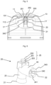
- Fig. 1 :
- Une vue en perspective du diffuseur selon l'invention ;
- Fig. 2 :
- Une vue en coupe longitudinale du diffuseur de la
figure 1 ; - Fig. 3 :
- Un agrandissement de la coupe de la
figure 2 au niveau des moyens d'accrochage du conduit de sortie ; - Fig. 4 :
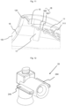
- Une vue en perspective d'une coupe transversale décentrée du diffuseur montrant les moyens anti-rotation ;
- Fig. 5 :
- Une vue en coupe transversale du diffuseur de la
figure 1 ; - Fig. 6 :
- Une vue en perspective du conduit de sortie ;
- Fig. 7 :
- Une vue en coupe longitudinale du conduit de sortie de la
figure 6 ; - Fig. 8 :
- Une vue en perspective du corps de base ;
- Fig. 9 :
- Une vue en coupe longitudinale du corps de base de la
figure 8 ; - Fig. 10 :
- Une vue en perspective d'une coupe longitudinale décentrée du corps de base de la
figure 8 ; - Fig. 11 :
- Une coupe longitudinale en perspective agrandie du corps de base au niveau du trou d'accrochage ;
- Fig. 12 :
- Une vue en perspective d'une variante du conduit de sortie de la
figure 6 .
- Fig. 1:
- A perspective view of the diffuser according to the invention;
- Fig. 2:
- A longitudinal sectional view of the diffuser of the
figure 1 ; - Fig. 3:
- An enlargement of the section of the
figure 2 at the level of the means for attaching the outlet conduit; - Fig. 4:
- A perspective view of an off-center cross section of the diffuser showing the anti-rotation means;
- Fig. 5:
- A cross-sectional view of the diffuser of the
figure 1 ; - Fig. 6:
- A perspective view of the outlet conduit;
- Fig. 7:
- A longitudinal sectional view of the outlet duct of the
Figure 6 ; - Fig. 8:
- A perspective view of the base body;
- Fig. 9:
- A longitudinal sectional view of the basic body of the
figure 8 ; - Fig. 10:
- A perspective view of an off-center longitudinal section of the basic body of the
figure 8 ; - Fig. 11:
- A longitudinal section in enlarged perspective of the base body at the level of the hanging hole;
- Fig. 12:
- A perspective view of a variant of the outlet conduit of the
Figure 6 .
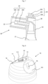
L'invention concerne un diffuseur (1) pour récipients sous pression, notamment pour générateurs d'aérosol, générateurs de mousse, systèmes de distribution de gels, de crèmes, de produits pâteux ou liquides. Il est destiné à actionner la valve du récipient en vue de prélever une partie au moins du contenu du récipient et de le distribuer par exemple sous forme d'aérosol ou de mousse. Les récipients sous pression sont constitués généralement d'un boîtier muni d'un col fermé par une valve montée sur une coupelle de valve. Il arrive que la coupelle de valve soit fixée au boîtier par l'intermédiaire d'un dôme. Quand la valve est de type mâle, un gicleur (stem) saille de la valve.The invention relates to a diffuser (1) for pressure containers, in particular for aerosol generators, foam generators, dispensing systems for gels, creams, pasty or liquid products. It is intended to activate the valve of the container with a view to taking at least part of the contents of the container and distributing it, for example in the form of an aerosol or foam. Pressure vessels generally consist of a housing fitted with a neck closed by a valve mounted on a valve cup. Sometimes the valve cup is attached to the housing via a dome. When the valve is male type, a nozzle (stem) protrudes from the valve.
De façon traditionnelle, le diffuseur comprend un corps de base (10) muni d'un doigtier (11), et un conduit de sortie (20) situé à l'intérieur du corps de base. Le doigtier (11) sert de bouton poussoir pour déplacer le conduit de sortie (20) en direction du générateur d'aérosol en vue d'actionner sa valve. Conformément à l'invention, le conduit de sortie (20) et le corps de base (10) sont deux pièces distinctes, le conduit de sortie étant configuré pour être fixé par des moyens d'accrochage au corps de base.Traditionally, the diffuser comprises a base body (10) provided with a finger cot (11), and an outlet conduit (20) located inside the base body. The finger cot (11) serves as a push button to move the outlet conduit (20) towards the aerosol generator in view to activate its valve. According to the invention, the outlet conduit (20) and the base body (10) are two separate parts, the outlet conduit being configured to be fixed by hooking means to the base body.
Le diffuseur présente une certaine géométrie de rotation autour d'un axe principal (A). Les adjectifs « radial » et « axial » se rapportent à cet axe principal. Quand le diffuseur est monté sur le récipient sous pression, cet axe principal (A) est aligné avec le stem de la valve, ou de façon plus générale avec l'axe principal du corps de valve. Le corps de base est formé d'une paroi concave formant une cavité. Par la suite, les termes « intérieur » et « extérieur » qualifient respectivement les éléments qui sont dans ou vers la cavité et ceux qui sont hors ou écartés de la cavité.The diffuser has a certain rotation geometry around a main axis (A). The adjectives “radial” and “axial” refer to this main axis. When the diffuser is mounted on the pressure vessel, this main axis (A) is aligned with the stem of the valve, or more generally with the main axis of the valve body. The basic body is formed of a concave wall forming a cavity. Subsequently, the terms “interior” and “exterior” respectively qualify the elements which are in or towards the cavity and those which are outside or away from the cavity.
Le conduit de sortie (20) a une première extrémité (21) configurée pour coopérer avec la valve ; il est pour cela muni à cette première extrémité de moyens pour coopérer avec la valve. Si la valve est une valve de type femelle, l'extrémité comprend une tige destinée à pénétrer dans la valve pour l'actionner. Si la valve est de type mâle, la première extrémité (21) est évasée pour faciliter l'introduction du stem lors du montage du diffuseur sur le récipient sous pression. La deuxième extrémité (22) du conduit de sortie débouche vers l'extérieur et peut être munie d'une buse pour améliorer la qualité de l'aérosol. Si la sortie du produit ne se fait pas dans l'alignement de la valve, le conduit de sortie est divisé entre au moins un premier tronçon (23) sensiblement rectiligne et un deuxième tronçon (24) incliné par rapport au premier. Le premier tronçon commence à la première extrémité (21) et se termine à la jonction avec le deuxième tronçon (24), et le deuxième tronçon (24) commence à la jonction avec le premier tronçon (23) et se termine à la deuxième extrémité (22). Pour permettre la mise en place d'une buse, le deuxième tronçon (24) peut être muni du côté de la deuxième extrémité d'un logement de buse (241). Dans l'exemple présenté ici, le deuxième tronçon (24) est constitué d'un conduit intérieur (242) composant à proprement parler une partie du conduit de sortie et qui est entourée par une paroi cylindrique (243) au moins du côté de la deuxième extrémité (22). L'espace annulaire entre le conduit intérieur (242) et la paroi cylindrique (243) constitue le logement de buse. Si le diffuseur n'est pas équipé d'une buse, il est possible de renoncer à la paroi cylindrique (243).The outlet conduit (20) has a first end (21) configured to cooperate with the valve; For this purpose it is provided at this first end with means for cooperating with the valve. If the valve is a female type valve, the end includes a stem intended to penetrate the valve to actuate it. If the valve is of the male type, the first end (21) is flared to facilitate the introduction of the stem when mounting the diffuser on the pressure vessel. The second end (22) of the outlet conduit opens outwards and can be fitted with a nozzle to improve the quality of the aerosol. If the product does not exit in alignment with the valve, the outlet conduit is divided between at least a first section (23) substantially rectilinear and a second section (24) inclined relative to the first. The first section begins at the first end (21) and ends at the junction with the second section (24), and the second section (24) begins at the junction with the first section (23) and ends at the second end (22). To allow the installation of a nozzle, the second section (24) can be provided on the side of the second end with a nozzle housing (241). In the example presented here, the second section (24) consists of an internal conduit (242) strictly speaking composing a part of the outlet conduit and which is surrounded by a cylindrical wall (243) at least on the side of the second end (22). The annular space between the inner conduit (242) and the cylindrical wall (243) constitutes the nozzle housing. If the diffuser is not equipped with a nozzle, it is possible to do without the cylindrical wall (243).
Pour accrocher le conduit de sortie (20) sur le corps de base (10), des moyens d'accrochage sont prévus dont une partie située sur le conduit de sortie (20) coopère avec une autre partie complémentaire réalisée dans le corps de base (10). Dans le présent exemple, les moyens d'accrochage du conduit de sortie sont constitués par un tenon d'encliquetage (25) destiné à s'encliqueter dans une ouverture d'encliquetage du corps de base constituant la partie complémentaire des moyens d'accrochage. Le tenon d'encliquetage (25) est placé au sommet du 1er tronçon (23), à l'opposé de la première extrémité (21). Il est de préférence coaxial à l'axe (A), mais ce n'est pas impératif. Le tenon d'encliquetage est constitué d'une tige sensiblement cylindrique (251) fixée par sa première extrémité au conduit de sortie et portant à sa deuxième extrémité un chapeau (252) de section transversale plus importante. La jonction entre la tige (251) et le reste du conduit de sortie constitue un épaulement (253) à distance du chapeau. Dans le cas présent, le tenon est en fait un cylindre dans lequel est réalisée une gorge annulaire. Le sommet du cylindre constitue le chapeau (252), la gorge annulaire forme la tige (251) et la partie du cylindre opposée au chapeau joue le rôle d'épaulement (253).To hang the outlet conduit (20) on the base body (10), hooking means are provided, a part of which located on the outlet conduit (20) cooperates with another complementary part made in the base body ( 10). In the present example, the means for attaching the outlet conduit are constituted by a latching pin (25) intended to latch into a latching opening of the base body constituting the complementary part of the attachment means. The latching pin (25) is placed at the top of the 1st section (23), opposite the first end (21). It is preferably coaxial with the axis (A), but it is not imperative. The latching tenon consists of a substantially cylindrical rod (251) fixed by its first end to the outlet conduit and carrying at its second end a cap (252) of larger cross section. The junction between the rod (251) and the rest of the outlet conduit constitutes a shoulder (253) at a distance from the cap. In the present case, the tenon is in fact a cylinder in which an annular groove is made. The top of the cylinder constitutes the cap (252), the annular groove forms the rod (251) and the part of the cylinder opposite the cap plays the role of shoulder (253).
Le corps de base (10) est constitué d'une paroi concave. Dans le présent exemple, il a une forme générale de dôme. Il pourrait également être cylindrique. Dans sa partie inférieure, située du côté du boîtier du récipient sous pression, le corps de base (10) est muni d'une bague de fixation (12) configurée pour le fixer soit directement au récipient sous pression, notamment sur le boîtier ou la valve, soit par le biais d'une virole, notamment dans le cas de diffuseurs de type ON/OFF. Cette bague de fixation est munie de moyens de fixation tels qu'une série de godrons (121) répartis régulièrement sur toute la périphérie de la bague de fixation. Ces moyens de fixation sont destinés à coopérer avec des moyens de fixation complémentaires réalisés sur le boîtier ou la valve du récipient sous pression, ou sur la virole. Notamment, les godrons (121) peuvent s'encliqueter derrière le bord roulé à l'interface entre le boîtier et la coupelle de valve ou entre le boîtier et le dôme sur lequel est fixée la coupelle de valve. D'autres moyens de fixation peuvent être envisagés, comme une nervure continue, un filetage pour un vissage, une surépaisseur de matière pour un soudage, de la colle pour un collage, etc.The base body (10) consists of a concave wall. In this example, it has a general dome shape. It could also be cylindrical. In its lower part, located on the housing side of the pressure vessel, the base body (10) is provided with a fixing ring (12) configured to fix it either directly to the pressure vessel, in particular on the housing or the valve, or by means of a ferrule, particularly in the case of ON/OFF type diffusers. This fixing ring is provided with fixing means such as a series of gadroons (121) distributed regularly over the entire periphery of the fixing ring. These fixing means are intended to cooperate with complementary fixing means made on the housing or the valve of the pressure vessel, or on the ferrule. In particular, the gadroons (121) can snap into place behind the rolled edge at the interface between the housing and the valve cup or between the housing and the dome on which the valve cup is fixed. Other means of fixing can be considered, such as a continuous rib, a thread for screwing, an extra thickness of material for welding, glue for bonding, etc.
La paroi du corps de base est percée d'une ouverture de doigtier (13) dans laquelle prend place le doigtier (11). Le doigtier est fixé au reste du corps de base par une languette (14) qui sert de charnière de sorte que lorsqu'une pression est exercée sur le doigtier vers l'intérieur du corps de base (donc vers la valve quand le diffuseur est monté sur le récipient sous pression), le doigtier pivote autour d'un axe traversant transversalement la languette. Dans l'exemple présenté ici, le doigtier (11) et l'ouverture (13) correspondante sont placés vers le sommet du corps de base. Il est préférable que la projection du doigtier (11) sur un plan perpendiculaire à l'axe principal (A) recouvre au moins la projection du premier tronçon (23) du conduit de sortie sur ledit plan perpendiculaire à l'axe principal (A). Autrement dit, le doigtier (11) se trouve au-dessus d'au moins le sommet du premier tronçon (23) du conduit de sortie.The wall of the base body is pierced with a finger cot opening (13) in which the finger cot (11) is placed. The finger cot is fixed to the rest of the base body by a tab (14) which serves as a hinge so that when pressure is exerted on the finger cot towards the inside of the base body (therefore towards the valve when the diffuser is mounted on the pressure vessel), the finger cot pivots around an axis passing transversely through the tongue. In the example presented here, the finger cot (11) and the corresponding opening (13) are placed towards the top of the base body. It is preferable that the projection of the finger cot (11) on a plane perpendicular to the main axis (A) covers at least the projection of the first section (23) of the outlet conduit on said plane perpendicular to the main axis (A). . In other words, the finger cot (11) is located above at least the top of the first section (23) of the outlet conduit.
Un orifice (15) est réalisé dans la paroi du corps de base en face de la deuxième extrémité (22) du conduit de sortie. Le produit prélevé du récipient sous pression qui sort du conduit de sortie par sa deuxième extrémité (22) traverse cet orifice (15). Cet orifice est de préférence oblong et s'étend dans un plan axial de sorte que la 2ème extrémité (22) du conduit de sortie, quand elle se déplace lors de l'actionnement de la valve, reste toujours en face de l'orifice (15). La deuxième extrémité (22) du conduit de sortie est donc flottante par rapport au corps de base (10) et à l'orifice (15) en particulier.An opening (15) is made in the wall of the base body opposite the second end (22) of the outlet conduit. The product taken from the pressure vessel which leaves the outlet conduit through its second end (22) passes through this orifice (15). This orifice is preferably oblong and extends in an axial plane so that the 2nd end (22) of the outlet conduit, when it moves during actuation of the valve, always remains facing the the orifice (15). The second end (22) of the outlet conduit is therefore floating relative to the base body (10) and to the orifice (15) in particular.
Un trou d'accrochage (16) est réalisé dans le corps de base (10) pour fixer le conduit de sortie (20). Ce trou constitue les moyens d'accrochage complémentaires pour la fixation du conduit de sortie (20) au corps de base (10). Le trou d'accrochage (16) est destiné à recevoir et retenir le tenon d'accrochage (15) du conduit de sortie. Il traverse de part en part la paroi du corps de base. Dans l'exemple présenté ici, il est divisé en deux parties : une partie intérieure (161) située vers l'intérieur du corps de base et une partie extérieure (162) débouchant sur la face extérieure du doigtier (11). La partie intérieure (161) est dimensionnée pour recevoir la tige (251) du tenon d'accrochage tandis que la partie extérieure, plus large, est dimensionnée pour recevoir le chapeau (252) du tenon. La partie extérieure (162) et le chapeau sont de préférence dimensionnés pour que le sommet du chapeau affleure la face extérieure du doigtier (11) et qu'il soit dans sa continuité. Notamment, la longueur de la partie extérieure (162) du trou d'accrochage (mesurée entre la jonction avec la partie intérieure (161) et la face extérieure de la paroi du corps de base) est de préférence sensiblement identique à la hauteur (mesurée entre la jonction du chapeau avec la tige et le sommet du chapeau opposé à la tige) du chapeau (252). Ainsi, dans l'exemple présenté ici, le sommet du chapeau (252) n'est pas perpendiculaire à la tige, mais légèrement incliné pour suivre la pente du doigtier à cet endroit. Le chapeau (252) et la partie intérieure (161) du trou d'accrochage sont dimensionnés pour que le chapeau puisse passer en force à travers la partie de tige lors du montage du conduit de sortie sur le corps de base sans que cela nécessite une force trop importante qui pourrait casser notamment le tenon d'accrochage (25). Autrement dit, la section transversale du chapeau (252) est supérieure à la section transversale de la partie intérieure (161) du trou d'accrochage. De façon plus générale, il suffit que la plus grande extension transversale de la section transversale du chapeau soit plus grande que la plus grande extension transversale de la section transversale de la partie intérieure du trou d'accrochage. Une fois que le chapeau est passé en force à travers la partie intérieure (161) du trou d'accrochage, il ne peut plus repasser tout seul, c'est-à-dire sans force extérieure, dans l'autre sens à travers cette partie intérieure. Lors d'une utilisation normale du diffuseur, aucune force particulière n'est exercée sur le conduit de sortie qui pourrait tendre à faire ressortir le tenon d'accrochage du trou d'accrochage. L'accrochage par le biais de l'encliquetage du tenon dans le trou d'accrochage est donc très bien adapté à un diffuseur.A hooking hole (16) is made in the base body (10) for fixing the outlet conduit (20). This hole constitutes the complementary hooking means for fixing the outlet conduit (20) to the base body (10). The hooking hole (16) is intended to receive and retain the hooking pin (15) of the outlet conduit. It passes right through the wall of the base body. In the example presented here, it is divided into two parts: an interior part (161) located towards the inside of the base body and an exterior part (162) opening onto the exterior face of the finger cot (11). The interior part (161) is dimensioned to receive the rod (251) of the hooking tenon while the exterior part, which is wider, is dimensioned to receive the cap (252) of the tenon. The exterior part (162) and the cap are preferably dimensioned so that the top of the cap is flush with the exterior face of the finger cot (11) and is in continuity with it. In particular, the length of the outer part (162) of the hanging hole (measured between the junction with the inner part (161) and the outer face of the wall of the base body) is preferably substantially identical to the height (measured between the junction of the cap with the stem and the top of the cap opposite the stem) of the cap (252). Thus, in the example presented here, the top of the cap (252) is not perpendicular to the stem, but slightly inclined to follow the slope of the finger cot at this location. The cap (252) and the interior part (161) of the hooking hole are dimensioned so that the cap can pass by force through the stem portion when mounting the outlet conduit on the base body without requiring a excessive force which could break in particular the hooking pin (25). In other words, the cross section of the cap (252) is greater than the cross section of the interior part (161) of the hanging hole. More generally, it is sufficient that the greatest transverse extension of the cross section of the cap is greater than the greatest transverse extension of the cross section of the interior part of the hooking hole. Once the hat has passed by force through the interior part (161) of the hanging hole, it can no longer pass again on its own, that is to say without external force, in the other direction through this interior part. During normal use of the diffuser, no particular force is exerted on the outlet duct which could tend to bring out the hooking pin from the hooking hole. Attachment by snapping the tenon into the attachment hole is therefore very well suited to a diffuser.
Pour empêcher le conduit de sortie (20) de pivoter autour de la tige d'accrochage (251) au risque que la deuxième extrémité (22) du conduit de sortie ne soit plus alignée avec l'orifice de sortie (15), il est préférable que le corps de base et/ou le conduit de sortie soient configurés pour maintenir la 2nde extrémité du conduit de sortie alignée avec l'orifice de sortie du produit (15). Pour cela, on peut prévoir des moyens anti-rotation. Dans le présent exemple, ces moyens anti-rotation sont constitués par deux pattes de guidage (17). Ces pattes de guidage se trouvent sur la face intérieure du corps de base, dans le présent exemple sur la face intérieure du doigtier (11), entre le trou d'accrochage (16) et l'orifice de sortie du produit (15). Elles sont placées en face l'une de l'autre de façon symétrique par rapport au plan longitudinal parallèle à l'axe principal (A) et passant par le centre du trou d'accrochage (16) et de l'orifice de sortie (15). Elles sont espacées l'une de l'autre de sorte à enserrer, ou pour le moins entourer avec très peu de jeu, le conduit de sortie (10). Pour faciliter la mise en place du conduit de sortie (10), la distance qui les sépare peut aller en s'élargissant légèrement en direction du centre du corps de base.To prevent the outlet conduit (20) from pivoting around the hooking rod (251) with the risk that the second end (22) of the outlet conduit is no longer aligned with the outlet orifice (15), it is preferably the base body and/or outlet conduit are configured to keep the 2nd end of the outlet conduit aligned with the product outlet port (15). For this, anti-rotation means can be provided. In the present example, these anti-rotation means consist of two guide tabs (17). These guide tabs are located on the interior face of the base body, in this example on the interior face of the finger cot (11), between the hooking hole (16) and the product outlet orifice (15). They are placed opposite each other symmetrically with respect to the longitudinal plane parallel to the main axis (A) and passing through the center of the hooking hole (16) and the outlet orifice ( 15). They are spaced from one another so as to enclose, or at least surround with very little play, the outlet conduit (10). To facilitate the installation of the outlet conduit (10), the distance which separates them can widen slightly towards the center of the base body.
Pour stabiliser le corps de base (10), le bord de l'ouverture de doigtier (13) peut se poursuivre par une jupe (131) dirigée vers le centre, laquelle jupe sert également de cache quand le doigtier (11) est enfoncé. De même, le pourtour du doigtier porte une jupe (112) dirigée vers l'intérieur. Des nervures de butée (18) peuvent également être prévues dans la cavité du corps de base pour limiter l'enfoncement du diffuseur sur le boîtier du récipient sous pression.To stabilize the base body (10), the edge of the finger cot opening (13) can be continued by a skirt (131) directed towards the center, which skirt also serves as a cover when the finger cot (11) is pressed. Likewise, the perimeter of the finger cot has a skirt (112) directed inwards. Stop ribs (18) can also be provided in the cavity of the base body to limit the sinking of the diffuser onto the housing of the pressure vessel.
En fonction de la longueur du deuxième tronçon (24) du conduit de sortie, il peut être nécessaire de rapprocher l'orifice de sortie du produit (15) du centre du corps de base. Pour cela, l'orifice de sortie (15) est placé dans un renfoncement (151) de la paroi du corps de base, lequel renfoncement est plus ou moins déformé, notamment concave considéré depuis l'extérieur du corps de base, selon la longueur du deuxième tronçon (24) du conduit de sortie.Depending on the length of the second section (24) of the outlet conduit, it may be necessary to move the product outlet port (15) closer to the center of the base body. For this, the outlet orifice (15) is placed in a recess (151) in the wall of the base body, which recess is more or less deformed, in particular concave considered from the outside of the base body, depending on the length of the second section (24) of the outlet conduit.
Lors du montage, le conduit de sortie (20) est introduit dans la cavité du corps de base (10), avec sa deuxième extrémité (22) dirigée vers l'orifice de sortie (15). Le tenon d'accrochage (25) est introduit dans le trou d'accrochage (16). Le chapeau (252) passe en force à travers la partie intérieure (161) jusqu'à déboucher dans la partie extérieure (162) dont la section transversale est suffisante pour le recevoir. Dans cette position, la tige (251) du tenon d'accrochage est placée dans la partie intérieure (161) du trou d'accrochage et l'épaulement (253) opposé au chapeau se trouve en contact, ou presque en contact, avec la face intérieure du doigtier (11). Parallèlement, le deuxième tronçon (24) du conduit de sortie passe entre les deux pattes de guidage (17) qui par leur forme guident le conduit de sortie exactement dans l'alignement de l'orifice de sortie (15). Ainsi, le conduit de sortie est retenu d'une part en translation axiale par le blocage de la paroi du doigtier au niveau du trou d'accrochage entre le chapeau (252) et l'épaulement (253), et d'autre part en rotation par le blocage du deuxième tronçon (24) entre les deux pattes de guidage (17).During assembly, the outlet conduit (20) is inserted into the cavity of the base body (10), with its second end (22) directed towards the outlet port (15). The hooking pin (25) is inserted into the hooking hole (16). The cap (252) passes by force through the interior part (161) until it emerges into the exterior part (162) whose cross section is sufficient to receive it. In this position, the rod (251) of the hooking pin is placed in the interior part (161) of the hooking hole and the shoulder (253) opposite the cap is in contact, or almost in contact, with the inner face of the finger cot (11). At the same time, the second section (24) of the outlet conduit passes between the two guide tabs (17) which by their shape guide the outlet conduit exactly in alignment with the outlet orifice (15). Thus, the outlet conduit is retained on the one hand in axial translation by blocking the wall of the finger cot at the level of the hooking hole between the cap (252) and the shoulder (253), and on the other hand in rotation by blocking the second section (24) between the two guide lugs (17).
Pour éviter que le doigt de l'utilisateur ne glisse sur le doigtier, il est possible de le munir de reliefs (111). Le chapeau (252) du tenon d'accrochage du conduit de sortie pourra se fondre parmi ces reliefs pour un effet plus esthétique. Notamment, il est possible que le chapeau (252) soit plus court que la partie extérieure (162) du trou d'accrochage, de sorte qu'il n'affleure pas la face extérieure du doigtier et forme un trou semblable aux autres reliefs.To prevent the user's finger from slipping on the finger cot, it is possible to provide it with reliefs (111). The cap (252) of the attachment pin of the outlet duct can blend in with these reliefs for a more aesthetic effect. In particular, it is possible that the hat (252) is shorter than the outer part (162) of the hanging hole, so that it is not flush with the outer face of the finger cot and forms a hole similar to the other reliefs.
De nombreuses variantes de réalisation sont possibles :
- La forme du chapeau (252) du tenon d'accrochage peut être non circulaire, donc sans symétrie de révolution. Si la forme de la partie extérieure (162) est complémentaire et ajustée à celle du chapeau, il est même possible de renoncer aux pattes de guidage (17) puisque le conduit de sortie est bloqué en rotation par l'emboîtement de forme du chapeau non circulaire dans la partie supérieure de forme complémentaire. La forme non circulaire de ces deux pièces et leur ajustement au moins partiel constituent des moyens anti-rotation.
- La partie extérieure (162) du trou d'accrochage n'a pas nécessairement la même forme que le chapeau (252) du tenon d'accrochage. Il suffit que le chapeau puisse s'y loger, même en dépassant ou en étant en retrait de la face extérieure du corps de base et même non bloqué en rotation puisque les pattes de guidage, ou un ajustement serrant ou l'emboîtement de forme de la tige (251) dans la partie intérieure (161) du trou d'accrochage, permettent de bloquer la rotation du conduit de sortie.
- Il est possible de renoncer à la partie extérieure (162) du trou d'accrochage en prévoyant la tige (251) du tenon d'accrochage et la partie intérieure (161) du trou d'accrochage plus longues et en laissant dépasser le chapeau au-dessus de la face extérieure du doigtier (11).
- Le tenon d'accrochage peut n'être constitué que d'une tige pénétrant en force dans un trou correspondant du corps de base. Dans une variante qui n'est pas selon les revendications, ce trou n'a pas besoin d'être traversant, un trou borgne pouvant suffire si l'épaisseur du corps de base à cet endroit est assez épaisse. Ici aussi, il est possible de renoncer aux pattes de guidage puisque l'ajustement serrant de la tige suffit à bloquer en rotation le conduit de sortie. Si le trou d'accrochage est traversant, la forme ou la couleur de la tige d'accrochage, ou du moins de son extrémité libre, peut également servir d'indication comme cela sera expliqué plus bas.
- Si le tenon n'a pas de chapeau et que le trou d'accrochage est traversant, on peut prévoir que l'extrémité libre de la tige du tenon ait une forme particulière, par exemple un triangle ou une étoile, et que la partie extérieure (162) du trou d'accrochage ait une forme complémentaire. La section transversale de l'extrémité libre de la tige peut à cet effet être identique à celle du reste de la tige (ronde par exemple) ou être plus petite ou pour le moins être inscrite dans la section transversale du reste de la tige. L'ajustement serrant du tenon dans le trou peut se limiter à la partie intérieure (162) ou à la partie extérieure (162) du trou d'accrochage.
- Dans une variante qui n'est pas selon les revendications, le conduit de sortie peut être fixé à une autre partie du corps de base (10), notamment dans le plan longitudinal passant par l'axe principal (A) et le centre de l'orifice de sortie du produit (15). On peut par exemple prévoir de le fixer entre la bague de fixation (12) et l'orifice de sortie du produit (15), ou au contraire à l'opposé de l'orifice de sortie du produit (15). Dans un tel cas, on peut prévoir au sommet du conduit de sortie une surface d'appui sur laquelle appuie le doigtier (11) quand l'utilisateur l'enfonce pour actionner la valve.
- Dans une variante qui n'est pas selon les revendications, le conduit de sortie (20) peut être fixé au corps de base par tout autre moyen d'accrochage mécanique. On peut par exemple prévoir sur la face intérieure du corps de base des fentes dans lesquels les bords latéraux du chapeau (252) peuvent coulisser jusqu'à la position voulue où ils peuvent s'encliqueter ou être retenus en place en raison de l'étroitesse des fentes à cet endroit. On peut également prévoir des tenons d'encliquetage sur l'une des pièces et des fentes d'encliquetage complémentaires sur l'autre pièce.
- The shape of the cap (252) of the hooking pin can be non-circular, therefore without symmetry of revolution. If the shape of the exterior part (162) is complementary and adjusted to that of the cap, it is even possible to dispense with the guide tabs (17) since the outlet conduit is blocked in rotation by the interlocking shape of the cap not circular in the upper part of complementary shape. The non-circular shape of these two parts and their at least partial adjustment constitute anti-rotation means.
- The outer part (162) of the hooking hole does not necessarily have the same shape as the cap (252) of the hooking pin. It is enough that the cap can be accommodated there, even when protruding or being set back from the exterior face of the base body and even not blocked in rotation since the guide tabs, or a tight fit or the interlocking shape of the rod (251) in the interior part (161) of the hooking hole, makes it possible to block the rotation of the outlet conduit.
- It is possible to dispense with the outer part (162) of the hooking hole by providing the rod (251) of the hooking pin and the inner part (161) of the hooking hole longer and allowing the cap to protrude at the -above the exterior face of the finger cot (11).
- The hooking pin may consist only of a rod penetrating by force into a corresponding hole in the base body. In a variant which is not according to the claims, this hole does not need to be through, a blind hole may be sufficient if the thickness of the base body at this location is thick enough. Here too, it is possible to dispense with the guide lugs since the tight fit of the rod is sufficient to block the outlet duct from rotating. If the hooking hole is through, the shape or color of the hooking rod, or at least of its free end, can also serve as an indication as will be explained below.
- If the tenon does not have a cap and the hooking hole is through, it can be provided that the free end of the rod of the tenon has a particular shape, for example a triangle or a star, and that the outer part (162) of the hanging hole has a complementary shape. The cross section of the free end of the rod can for this purpose be identical to that of the rest of the rod (round for example) or be smaller or at least be included in the cross section of the rest of the rod. The tight fit of the tenon in the hole can be limited to the interior portion (162) or the exterior portion (162) of the hooking hole.
- In a variant which is not according to the claims, the outlet conduit can be fixed to another part of the base body (10), in particular in the longitudinal plane passing through the main axis (A) and the center of the the product outlet port (15). We can for example plan to fix it between the fixing ring (12) and the orifice of product outlet (15), or on the contrary opposite the product outlet orifice (15). In such a case, a support surface can be provided at the top of the outlet conduit on which the finger cot (11) rests when the user presses it to operate the valve.
- In a variant which is not according to the claims, the outlet conduit (20) can be fixed to the base body by any other mechanical attachment means. For example, slots can be provided on the interior face of the base body in which the side edges of the cap (252) can slide to the desired position where they can snap into place or be held in place due to the narrowness. slots there. It is also possible to provide latching pins on one of the parts and complementary latching slots on the other part.
L'invention permet de se concentrer particulièrement sur le conduit de sortie (20), qui est essentielle pour la qualité de pulvérisation, le reste du diffuseur, à savoir le corps de base, n'étant qu'un habillage. Il est possible d'avoir des canaux très courts, ce qui est favorable notamment dans le cas de l'utilisation de gaz comprimés. Le corps de base et le conduit de sortie peuvent être fabriqués dans des usines différentes, ce qui limite les problèmes liés au transport. Un même conduit de sortie peut être utilisé avec des corps de base de couleur et/ou de matériau différents, et un même corps de base peut être utilisé avec des conduits de sortie de qualités différentes. De nombreuses combinaisons sont donc possibles.The invention makes it possible to concentrate particularly on the outlet duct (20), which is essential for the spray quality, the rest of the diffuser, namely the basic body, being only a covering. It is possible to have very short channels, which is favorable particularly when using compressed gases. The base body and the outlet duct can be manufactured in different factories, which limits transportation problems. The same outlet duct can be used with base bodies of different color and/or material, and the same base body can be used with outlet ducts of different qualities. Many combinations are therefore possible.
Grâce à l'invention, il est possible d'utiliser deux matériaux différents pour le conduit de sortie (20) et pour le corps de base (10). Le matériau du conduit de sortie sera choisi pour être compatible avec le produit à prélever, tandis que le matériau du corps de base n'aura pas besoin de remplir cette condition, mais pourra être choisi pour ses propriétés mécaniques notamment. Par exemple, si le diffuseur est destiné à un produit alimentaire, le matériau du conduit de sortie devra être de qualité alimentaire, tandis que celui du corps de base n'aura pas besoin de l'être et pourra être plus économique. En utilisant des moyens d'accrochage mécanique, en particulier par encliquetage, il n'est pas nécessaire que les deux matériaux soient compatibles entre eux. Il n'est pas non plus nécessaire de prévoir une injection bimatière. Parmi les matériaux envisageables pour le corps de base, on peut citer les matériaux polymères (PE, PP, PLA, PHA, PBS) qu'ils soient vierges ou recyclés, issus du pétrole ou de ressources naturelles, biodégradables ou non, voire compostables ou non. Ils peuvent contenir des charges minérales (verre, basalte), être renforcés par des fibres minérales ou végétales. On peut également envisager des matériaux non polymères, tels que des matériaux à base de lignine (carton, bois), des matériaux contenant des textiles, des métaux, etc. Pour le conduit de sortie, on peut citer à titre d'exemple non limitatif les polymères (PE, PP, POM, PBT, PA) ou les métaux (aluminium, acier, notamment acier inoxydable).Thanks to the invention, it is possible to use two different materials for the outlet duct (20) and for the base body (10). The material of the outlet conduit will be chosen to be compatible with the product to be sampled, while the material of the base body will not need to fulfill this condition, but can be chosen for its mechanical properties in particular. For example, if the diffuser is intended for a food product, the material of the outlet duct will need to be food grade, while that of the base body will not need to be and may be more economical. By using mechanical attachment means, in particular by snap-fastening, it is not necessary for the two materials to be compatible with each other. It is also not necessary to provide a two-material injection. Among the possible materials for the base body, we can cite polymer materials (PE, PP, PLA, PHA, PBS) whether virgin or recycled, derived from petroleum or natural resources, biodegradable or not, even compostable or No. They can contain mineral fillers (glass, basalt), be reinforced with mineral or plant fibers. One can also consider non-polymeric materials, such as lignin-based materials (cardboard, wood), materials containing textiles, metals, etc. For the outlet conduit, we can cite, as a non-limiting example, polymers (PE, PP, POM, PBT, PA) or metals (aluminum, steel, in particular stainless steel).
L'extrémité de la tige, notamment le chapeau, et/ou le trou d'accrochage peuvent être configurés pour transmettre une information à l'utilisateur. La couleur et/ou la forme de l'extrémité de la tige, et notamment du chapeau (252), peuvent servir d'information pour l'utilisateur, et notamment de moyens d'identification. Par exemple, si l'un des deux matériaux au moins est un biomatériau ou un matériau recyclé, on pourra par exemple colorer le conduit de sortie en vert de sorte que le chapeau (252) forme une pastille verte sur le doigtier. Un fabricant pourra ainsi communiquer auprès de sa clientèle sur sa volonté stratégique de s'inscrire dans une politique de développement durable. Il est également possible de donner au chapeau une autre forme que circulaire. On pourrait par exemple lui donner une forme d'étoile ou de croissant de lune, qui pourrait être utilisée non seulement comme moyen anti-rotation, mais également pour indiquer que le produit contenu est à utiliser le soir (par exemple une crème de nuit).The end of the rod, in particular the cap, and/or the hanging hole can be configured to transmit information to the user. The color and/or shape of the end of the rod, and in particular of the cap (252), can serve as information for the user, and in particular as means of identification. For example, if at least one of the two materials is a biomaterial or a recycled material, we could for example color the outlet conduit green so that the cap (252) forms a green patch on the finger cot. A manufacturer will thus be able to communicate with its customers about its strategic desire to be part of a sustainable development policy. It is also possible to give the hat a shape other than circular. For example, it could be given the shape of a star or crescent moon, which could be used not only as an anti-rotation means, but also to indicate that the product contained is to be used in the evening (for example a night cream). .
Pour faciliter la manipulation des conduits de sortie, on peut les munir d'ailettes d'assemblage (244), notamment sur le deuxième tronçon (24), qui permettent de guider correctement les conduits de sortie dans la machine d'assemblage.To facilitate the handling of the outlet ducts, they can be fitted with assembly fins (244), particularly on the second section (24), which make it possible to correctly guide the outlet ducts in the assembly machine.
Le tenon d'accrochage pouvant être à une certaine distance de la jonction entre le premier tronçon (23) et le deuxième tronçon (24) du conduit de sortie, il est préférable de prévoir un évidement (26) dans la matière située entre cette jonction et le tenon d'accrochage. Dans l'exemple présenté ici, l'épaulement (253) du tenon d'accrochage est placé sur la paroi supérieure de cet évidement.The hooking pin can be at a certain distance from the junction between the first section (23) and the second section (24) of the outlet conduit, it is preferable to provide a recess (26) in the material located between this junction and the hooking pin. In the example presented here, the shoulder (253) of the hooking pin is placed on the upper wall of this recess.
- 11
- DiffuseurStreamer
- 1010
-
Corps de base
11 Doigtier
111 Reliefs antiglisse
112 Jupe de renfort
12 Bague de fixation
121 Moyens de fixationBasic body
11 Finger cot
111 Anti-slip reliefs
112 Reinforcement skirt
12 Fixing ring
121 Fixing means
- 1313
-
Ouverture de doigtier
131 Jupe de renfortFinger cot opening
131 Reinforcement skirt
- 1414
- LanguetteTongue
- 1515
-
Orifice de sortie du produit
151 RenfoncementProduct outlet port
151 Recess
- 1616
-
Trou d'accrochage
161 Partie intérieure
162 Partie extérieureHanging hole
161 Interior part
162 Exterior part
- 1717
- Pattes de guidageGuide legs
- 1818
- Nervures de butéeStop ribs
- 2020
-
Conduit de sortie
21 1ère extrémité
22 2ème extrémité
23 1er tronçon
24 2ème tronçon
241 Logement de buse
242 Conduit intérieur
243 Paroi cylindrique
244 Ailettes d'assemblage
25 Tenon d'accrochage
251 Tige du tenon d'encliquetage
252 Chapeau du tenon d'encliquetage
253 Épaulement
26 ÉvidementOutlet conduit
21 1st end
22 2nd end
23 1st section
24 2nd section
241 Nozzle housing
242 Internal conduit
243 Cylindrical wall
244 Assembly fins
25 Hooking pin
251 Shaft of the latching tenon
252 Snap-in tenon cap
253 Shoulder
26 Recess
- AHAS
- Axe principalMain axis
Claims (18)
- Diffuser for a pressurized container provided with a valve, in particular for an aerosol generator, which diffuser (1) is provided with- a base body (10) formed of a wall having a concave face forming a cavity, and having a finger tab (11) intended to be depressed by the user to actuate the valve, and- an outlet conduit (20) placed in the cavity of the base body (10), which conduit has a first end (21) provided with means for cooperating with the valve of the pressurized container, and a second end (22) for the outlet of the product contained in the pressurized container,the outlet conduit (20) and the base body (10) being two distinct parts which are connected together by mechanical fastening means (25, 16), wherein anti-rotation means (17) can be provided to prevent the outlet conduit from rotating relative to the base body,the mechanical fastening means being constituted by a fastening tenon (25) and a fastening hole (16), the fastening tenon being placed on the outlet conduit (20) and the fastening hole being made in the wall of the base body (10) and opening into the cavity,an orifice (15) being made in the wall of the base body, facing the second end (22) of the outlet conduit and at a distance from the fastening hole (16),characterized in that
the fastening hole (16) is a hole passing through the wall of the base body, and is intended to receive and retain the fastening tenon (15) of the outlet conduit. - Diffuser according to the preceding claim, characterized in that the end of the fastening tenon (25) opposite the rest of the outlet conduit (20) has a particular shape and/or color which, in the fastened state of the outlet conduit, is/are visible and recognizable from the outside of the diffuser and constitute(s) means of identification or information for the user.
- Diffuser according to one of the preceding claims, characterized in that- the fastening hole (16) is made in the finger tab (11) of the base body (10),- the fastening tenon (25) comprises a cap (252) connected to the outlet conduit by a rod (251) which ends with a shoulder (253) opposite the cap,- the fastening hole (16) comprises at least a first portion, called inner portion (161), the greatest transverse extension of which is less than the greatest transverse extension of the cap (252) of the fastening tenon, a length of the rod (251) of the tenon being chosen so that, in the fastened state of the outlet conduit, the wall of the base body (10) at the edge of the fastening hole (16) is located between the cap (252) and the shoulder (253), a transverse cross-section of the cap (252) and a transverse cross-section of the inner portion (161) being chosen so that when fastening the outlet conduit, the cap can be introduced by force into the inner portion (161) of the fastening hole without risking damage to the outlet conduit or to the base body (10).
- Diffuser according to the preceding claim, characterized in that the inner portion (161) of the fastening hole (16) continues with a second portion, called outer portion (162), the inner portion opening into the cavity of the base body (10) and the outer portion opening to the outside of the base body (10), a transverse cross-section of the outer portion (162) being dimensioned to contain a transverse cross-section of the cap (252) of the fastening tenon, a length of the outer portion (162) of the fastening hole preferably being substantially identical to a height of the cap (252) so that the latter is flush with the outer face of the base body.
- Diffuser according to one of the preceding claims, characterized in that- the outlet conduit (20) comprises a first section (23) which is substantially rectilinear and a second section (24), the first section starting at the first end (21) of the outlet conduit and ending at the junction with the second section (24),- the fastening tenon (25) is placed at the top of the first section (23) opposite the first end (21), or on the second section (24),- the fastening opening (16) is made in the finger tab (11).
- Diffuser according to one of the preceding claims, characterized in that the anti-rotation means are constituted by a tight fit of the fastening tenon (25) in the fastening hole (16), a transverse cross-section of the fastening tenon, in particular of the rod (251) of the fastening tenon when the fastening tenon is provided with a rod, preferably being greater than a transverse cross-section of at least a portion of the fastening hole (16), in particular of the inner portion (161) of the fastening hole when the fastening hole is provided with an inner portion.
- Diffuser according to one of the preceding claims, characterized in that the anti-rotation means are constituted by an interlocking of shapes of the fastening tenon (25) in the fastening hole (16), in particular of the rod (251) of the fastening tenon in the inner portion (161) of the fastening hole when the fastening tenon is provided with a rod and the fastening hole is provided with an inner portion, a transverse cross-section of the fastening tenon, in particular of the rod (251) of the fastening tenon when the fastening tenon is provided with a rod, and a transverse cross-section of the fastening hole, in particular of the inner portion (161) of the fastening hole when the fastening hole is provided with an inner portion, not having a symmetry of revolution and preferably being complementary.
- Diffuser according to claim 4, or one of claims 5 to 7 associated to claim 4, characterized in that the anti-rotation means are constituted by an interlocking of shapes of the cap (252) of the fastening tenon in the outer portion (162) of the fastening hole, the transverse cross-section of the cap (252) of the fastening tenon and the transverse cross-section of the outer portion (162) of the fastening hole not having a symmetry of revolution, and preferably being complementary.
- Diffuser according to one of the preceding claims, characterized in that the anti-rotation means are constituted by two guide lugs (17) placed in the cavity of the base body and which surround a portion of the outlet conduit, in particular the second section (24) when the outlet conduit is provided with a second portion, while preventing the latter from pivoting around the fastening tenon (25).
- Diffuser according to one of the preceding claims, characterized in that the material used for the base body and the material used for the outlet conduit are of different compositions and/or of different colors.
- Diffuser according to claim 3 or one of claims 4 to 10 associated to claim 3, characterized in that the cap (252) has a particular shape and/or color which, in the fastened state of the outlet conduit, is/are visible and recognizable from the outside of the diffuser and constitute(s) means of identification or information for the user.
- Diffuser according to one of the preceding claims, characterized in that the base body is provided with fixing means (121) to fix it directly or via a ferrule to a pressurized container.
- Diffuser according to one of the preceding claims, characterized in that the orifice (15) made in the wall of the base body is placed in a recess (151) of the wall of the base body, which recess, viewed from outside the base body, preferably has a concave shape.
- Diffuser according to one of the preceding claims, characterized in that at least a portion of the base body (10) and/or at least a portion of the outlet conduit (20) is/are made in a recycled material, in a biodegradable material, in a compostable material or in a biomaterial, or a mixture thereof.
- Diffuser according to one of the preceding claims, characterized in that the base body (10) is made in a material chosen from among:- a polymer material, preferably polyethylene (PE), polypropylene (PP), polylactic acid (PLA), polyhydroxyalkanoates (PHA), polybutylene succinate (PBS), or a mixture thereof, which polymer can contain mineral fillers, in particular glass and/or basalt, and/or be reinforced with mineral or vegetable fibers,- a lignin-based material, preferably cardboard and/or wood,- a material containing textiles,- a metal,- a mixture of these materials.
- Diffuser according to one of the preceding claims, characterized in that the outlet conduit (20) is made in a food grade and/or cosmetic grade and/or pharmaceutical grade and/or medical grade material.
- Diffuser according to one of the preceding claims, characterized in that the outlet conduit (20) is made in a material chosen from among:- a polymer material, preferably polyethylene (PE), polypropylene (PP), polyoxymethylene (POM), poly(butylene terephthalate) (PBT), polyamide (PA), or a mixture thereof,- a metal, preferably aluminum or steel, in particular stainless steel.
- Diffuser according to one of the preceding claims, characterized in that the outlet conduit (20) is made in a virgin material and the main body is made at least partly in a recycled material.
Applications Claiming Priority (2)
| Application Number | Priority Date | Filing Date | Title |
|---|---|---|---|
| FR1900676A FR3092091B1 (en) | 2019-01-25 | 2019-01-25 | Diffuser for pressure vessel |
| PCT/EP2020/051372 WO2020152141A1 (en) | 2019-01-25 | 2020-01-21 | Diffuser for a pressurized container |
Publications (3)
| Publication Number | Publication Date |
|---|---|
| EP3914534A1 EP3914534A1 (en) | 2021-12-01 |
| EP3914534B1 true EP3914534B1 (en) | 2024-02-28 |
| EP3914534C0 EP3914534C0 (en) | 2024-02-28 |
Family
ID=66867418
Family Applications (4)
| Application Number | Title | Priority Date | Filing Date |
|---|---|---|---|
| EP20700735.2A Pending EP3914532A1 (en) | 2019-01-25 | 2020-01-21 | Diffuser outlet duct |
| EP20700734.5A Pending EP3914531A1 (en) | 2019-01-25 | 2020-01-21 | Dispenser for a pressurised container |
| EP20701453.1A Active EP3914534B1 (en) | 2019-01-25 | 2020-01-21 | Diffuser for a pressurized container |
| EP20700736.0A Pending EP3914533A1 (en) | 2019-01-25 | 2020-01-21 | Dispenser for a pressurised container |
Family Applications Before (2)
| Application Number | Title | Priority Date | Filing Date |
|---|---|---|---|
| EP20700735.2A Pending EP3914532A1 (en) | 2019-01-25 | 2020-01-21 | Diffuser outlet duct |
| EP20700734.5A Pending EP3914531A1 (en) | 2019-01-25 | 2020-01-21 | Dispenser for a pressurised container |
Family Applications After (1)
| Application Number | Title | Priority Date | Filing Date |
|---|---|---|---|
| EP20700736.0A Pending EP3914533A1 (en) | 2019-01-25 | 2020-01-21 | Dispenser for a pressurised container |
Country Status (8)
| Country | Link |
|---|---|
| US (4) | US20220097951A1 (en) |
| EP (4) | EP3914532A1 (en) |
| AR (4) | AR117857A1 (en) |
| BR (4) | BR112021014595A2 (en) |
| CA (4) | CA3126619A1 (en) |
| FR (1) | FR3092091B1 (en) |
| MX (4) | MX2021008841A (en) |
| WO (4) | WO2020152141A1 (en) |
Families Citing this family (3)
| Publication number | Priority date | Publication date | Assignee | Title |
|---|---|---|---|---|
| FR3092091B1 (en) | 2019-01-25 | 2021-08-13 | Lindal France | Diffuser for pressure vessel |
| FR3099470B1 (en) | 2019-07-29 | 2021-09-10 | Lindal France | Pressure vessel valve |
| ES1285316Y (en) * | 2021-11-03 | 2022-04-20 | Zenit Estudio De Diseno E Innovacion S L | ACTUATOR COVER WITH INTERNAL DRUM |
Family Cites Families (51)
| Publication number | Priority date | Publication date | Assignee | Title |
|---|---|---|---|---|
| US3058626A (en) * | 1959-06-22 | 1962-10-16 | George W Hibbs | Cap for spray dispenser, or the like |
| US3567081A (en) * | 1969-01-30 | 1971-03-02 | Philip Meshberg | Multidirectional aerosol dispenser |
| US3858762A (en) * | 1972-11-09 | 1975-01-07 | Philip Meshberg | Actuator assembly for an encased dispenser and method |
| US4019584A (en) * | 1975-12-01 | 1977-04-26 | Richmond Industries, Inc. | Fire extinguisher |
| FR2429161A1 (en) | 1978-06-19 | 1980-01-18 | Aerosol Inventions Dev | DISTRIBUTION ASSEMBLY FOR AEROSOL VALVE |
| US4328911A (en) | 1980-07-23 | 1982-05-11 | Seaquist Valve Company | Child resistant aerosol actuating overcap |
| US4416399A (en) | 1981-06-12 | 1983-11-22 | Ziphron, Inc. | Aerosol canister |
| GB8306856D0 (en) * | 1983-03-12 | 1983-04-20 | Metal Box Plc | Aerosol actuator |
| FR2556242B1 (en) * | 1983-12-07 | 1986-08-22 | Aerosol Inventions Dev | IMMEDIATE AND DELAYED DOUBLE ACTION ATMOSPHERE DIFFUSER, AND AEROSOL PACKAGING PROVIDED WITH SUCH A DIFFUSER |
| KR880701137A (en) * | 1986-04-25 | 1988-07-25 | 이시바시 유끼히로 | Spray head with guard |
| US4815541A (en) | 1987-06-29 | 1989-03-28 | Arrington Richard C | Fire extinguisher |
| JPH0835971A (en) * | 1994-07-25 | 1996-02-06 | Hitachi Ltd | Pipet |
| FR2767799B1 (en) * | 1997-08-27 | 2000-05-12 | Oreal | PACKAGING ASSEMBLY OF A LIQUID OR SEMI-LIQUID PRODUCT |
| GB9727366D0 (en) * | 1997-12-24 | 1998-02-25 | Unilever Plc | Sprayhead |
| US6006957A (en) | 1998-03-06 | 1999-12-28 | S. C. Johnson & Son, Inc. | Actuator overcap for a pressurized canister |
| GB0003343D0 (en) * | 2000-02-14 | 2000-04-05 | Unilever Plc | Actuator mechanism |
| AU2001267516A1 (en) * | 2000-06-10 | 2001-12-24 | Wella Aktiengesellschaft | Container |
| US6454139B1 (en) | 2001-02-14 | 2002-09-24 | Precision Valve Corporation | Preassembled aerosol actuator assembly for in-line capping to an aerosol container |
| FR2839952B1 (en) * | 2002-05-24 | 2004-08-06 | Oreal | DISPENSING DEVICE FOR EQUIPPING A CONTAINER PROVIDED WITH A VALVE |
| US6908017B2 (en) | 2003-06-05 | 2005-06-21 | S. C. Johnson & Son, Inc. | Aerosol over cap with flip-up closure |
| DE602004020810D1 (en) * | 2004-03-18 | 2009-06-04 | Rust Oleum Netherlands B V | DISTRIBUTION DEVICE FOR GIVING A PRODUCT |
| DE102004022131A1 (en) | 2004-05-05 | 2005-11-24 | Boehringer Ingelheim Microparts Gmbh | Spray head for atomizing a medium |
| US20070290007A1 (en) * | 2004-11-30 | 2007-12-20 | The Procter & Gamble Company | Cap with an angled spray channel for an aerosol container or a spray container |
| FR2881721A1 (en) * | 2005-02-09 | 2006-08-11 | Innovation Packaging Sarl | Push button for pasty or liquid fluid e.g. liquid perfume, dispensing device, has nozzle body, connection socket, and lengthened tube that is deformed at level of its deformable sections in inclined position |
| ATE549957T1 (en) | 2005-06-16 | 2012-04-15 | Colgate Palmolive Europ Sarl | WATER-BASED DEODORANT AND AEROSOL DISPENSER |
| US20080221561A1 (en) * | 2005-07-18 | 2008-09-11 | Jorg Geiger | Spray Device for Dispensing a Cooling Fluid |
| US7204393B2 (en) * | 2005-08-12 | 2007-04-17 | Summit Packaging, Inc. | Spray actuating mechanism for a dispensing canister |
| US20070051754A1 (en) | 2005-09-08 | 2007-03-08 | Strand Toralf H | Button actuated mechanism for a dispensing canister |
| AU2007230663B2 (en) * | 2006-03-24 | 2011-03-17 | Colgate-Palmolive Company | Aerosol dispenser |
| US7530476B2 (en) * | 2006-04-10 | 2009-05-12 | Precision Valve Corporation | Locking aerosol dispenser |
| US8960503B2 (en) * | 2006-10-19 | 2015-02-24 | Atef Gabr Soliman | Plastic aerosol container |
| DE102007049614B4 (en) * | 2007-03-15 | 2015-03-05 | Aptar Dortmund Gmbh | dispenser |
| US7789278B2 (en) * | 2007-04-12 | 2010-09-07 | The Clorox Company | Dual chamber aerosol container |
| US8881944B2 (en) | 2008-06-30 | 2014-11-11 | S.C. Johnson & Son, Inc. | Overcap for and a method of actuating a volatile material dispenser |
| CN102791594A (en) | 2010-03-12 | 2012-11-21 | 三谷阀门有限公司 | Container cover and aerosol type product provided with container cover |
| DE202011000160U1 (en) | 2011-01-21 | 2012-04-23 | Lindal Dispenser Gmbh | spray nozzle |
| US9981799B2 (en) | 2011-08-09 | 2018-05-29 | S.C. Johnson & Son, Inc. | Dispensing system |
| DE102012200545A1 (en) * | 2012-01-16 | 2013-07-18 | Aptar Radolfzell Gmbh | media dispenser |
| US9435120B2 (en) * | 2013-03-13 | 2016-09-06 | Homax Products, Inc. | Acoustic ceiling popcorn texture materials, systems, and methods |
| JP5901564B2 (en) | 2013-04-03 | 2016-04-13 | 東洋エアゾール工業株式会社 | Fixed plate for aerosol container |
| US9776785B2 (en) | 2013-08-19 | 2017-10-03 | Ppg Architectural Finishes, Inc. | Ceiling texture materials, systems, and methods |
| ES2640713T3 (en) * | 2013-12-09 | 2017-11-06 | Unilever Nv | Spray dispensing head |
| US20160221744A1 (en) | 2015-01-29 | 2016-08-04 | Tremco Illbruck Productie B.V. | Dispenser head |
| FR3035380B3 (en) * | 2015-04-24 | 2017-05-12 | Lindal France | DISPENSING HEAD FOR AEROSOL CONTAINER PROVIDED WITH BLOCKING MEANS |
| US9862535B2 (en) * | 2016-02-12 | 2018-01-09 | S. C. Johnson & Son, Inc. | Overcap assembly |
| EP3251753B1 (en) | 2016-06-01 | 2019-07-31 | Aptar Radolfzell GmbH | Dispenser for discharging a liquid |
| DE102016221820A1 (en) | 2016-11-08 | 2018-05-09 | Beiersdorf Ag | Self-closing dispensing head |
| CN112770987B (en) | 2018-08-27 | 2023-06-13 | 约翰逊父子公司 | Trigger cap assembly |
| US11267644B2 (en) * | 2018-11-08 | 2022-03-08 | The Procter And Gamble Company | Aerosol foam dispenser and methods for delivering a textured foam product |
| FR3092091B1 (en) | 2019-01-25 | 2021-08-13 | Lindal France | Diffuser for pressure vessel |
| FR3106338A1 (en) | 2020-01-21 | 2021-07-23 | Lindal France | Diffuser for pressure vessel |
-
2019
- 2019-01-25 FR FR1900676A patent/FR3092091B1/en active Active
-
2020
- 2020-01-21 CA CA3126619A patent/CA3126619A1/en active Pending
- 2020-01-21 BR BR112021014595-8A patent/BR112021014595A2/en unknown
- 2020-01-21 US US17/423,974 patent/US20220097951A1/en active Pending
- 2020-01-21 CA CA3126617A patent/CA3126617A1/en active Pending
- 2020-01-21 WO PCT/EP2020/051372 patent/WO2020152141A1/en active Search and Examination
- 2020-01-21 US US17/420,380 patent/US11667461B2/en active Active
- 2020-01-21 WO PCT/EP2020/051335 patent/WO2020152125A1/en unknown
- 2020-01-21 US US17/423,987 patent/US11643267B2/en active Active
- 2020-01-21 EP EP20700735.2A patent/EP3914532A1/en active Pending
- 2020-01-21 MX MX2021008841A patent/MX2021008841A/en unknown
- 2020-01-21 MX MX2021008844A patent/MX2021008844A/en unknown
- 2020-01-21 BR BR112021012798-4A patent/BR112021012798A2/en unknown
- 2020-01-21 EP EP20700734.5A patent/EP3914531A1/en active Pending
- 2020-01-21 WO PCT/EP2020/051337 patent/WO2020152127A1/en active Application Filing
- 2020-01-21 MX MX2021007737A patent/MX2021007737A/en unknown
- 2020-01-21 CA CA3126616A patent/CA3126616A1/en active Pending
- 2020-01-21 AR ARP200100148A patent/AR117857A1/en active IP Right Grant
- 2020-01-21 WO PCT/EP2020/051336 patent/WO2020152126A1/en unknown
- 2020-01-21 BR BR112021014594-0A patent/BR112021014594A2/en unknown
- 2020-01-21 US US17/423,963 patent/US11661265B2/en active Active
- 2020-01-21 MX MX2021008846A patent/MX2021008846A/en unknown
- 2020-01-21 EP EP20701453.1A patent/EP3914534B1/en active Active
- 2020-01-21 CA CA3121314A patent/CA3121314A1/en active Pending
- 2020-01-21 EP EP20700736.0A patent/EP3914533A1/en active Pending
- 2020-01-21 AR ARP200100143A patent/AR117853A1/en active IP Right Grant
- 2020-01-21 AR ARP200100141A patent/AR117851A1/en active IP Right Grant
- 2020-01-21 BR BR112021014610-5A patent/BR112021014610A2/en unknown
- 2020-01-21 AR ARP200100142A patent/AR117852A1/en unknown
Also Published As
Similar Documents
| Publication | Publication Date | Title |
|---|---|---|
| EP3914534B1 (en) | Diffuser for a pressurized container | |
| EP1201318B1 (en) | Dispensing assembly for the simultaneous distribution of two products | |
| EP1751023B1 (en) | Perfume dispenser | |
| EP0881165B1 (en) | Packaging container for extemporaneously mixing two products | |
| WO2006129043A2 (en) | Assembly for fixing a fluid product dispensing member | |
| EP2442914B1 (en) | Fluid material dispenser | |
| EP3603817B1 (en) | Easy mounting and removal of a pump relative to the container | |
| WO2018115685A1 (en) | Refillable device for packaging a cosmetic product | |
| FR2845874A1 (en) | Container for product in extending stick form has product held in inner sleeve of different shape to outer wall | |
| EP0755872B1 (en) | Container provided with a distributing opening and a closure device | |
| EP3129157A1 (en) | Bottle and production method thereof | |
| FR2767794A1 (en) | SET OF TWO FREE MOUNTED ROTATING ELEMENTS IN RELATION TO THE OTHER, IN PARTICULAR FOR A MIXER IN THE FIELD OF HAIR COLORING | |
| FR2975674A1 (en) | FIXING RING AND FLUID PRODUCT DISPENSER USING SUCH RING. | |
| WO2008152282A2 (en) | Attachment device for attaching a pump on a tank and dispenser using such an attachment device | |
| EP4244157A1 (en) | Diffuser for aerosol generator | |
| WO2021148382A1 (en) | Dispenser for a pressurised container | |
| CA2422754A1 (en) | Pourer with improved locking and cap equipped with same | |
| EP3953050B1 (en) | Dispenser for a pressurised container | |
| EP1442998B1 (en) | Snap-on cap and container | |
| FR2630403A1 (en) | PIVOTING PLUG FOR DISPENSING LIQUID OR PASTY MATERIALS | |
| FR2868262A1 (en) | PRODUCT DISPENSER BODY OF PLASTIC AND MOBILE MATERIAL | |
| FR2845675A1 (en) | Fixing unit for fluid e.g. perfume, dispenser, has skirt with vent passing through thickness of skirt, and forming vent below large diameter top segment to come into contact with leaktight contact in opening of reservoir |
Legal Events
| Date | Code | Title | Description |
|---|---|---|---|
| STAA | Information on the status of an ep patent application or granted ep patent |
Free format text: STATUS: UNKNOWN |
|
| STAA | Information on the status of an ep patent application or granted ep patent |
Free format text: STATUS: THE INTERNATIONAL PUBLICATION HAS BEEN MADE |
|
| STAA | Information on the status of an ep patent application or granted ep patent |
Free format text: STATUS: THE INTERNATIONAL PUBLICATION HAS BEEN MADE |
|
| PUAI | Public reference made under article 153(3) epc to a published international application that has entered the european phase |
Free format text: ORIGINAL CODE: 0009012 |
|
| STAA | Information on the status of an ep patent application or granted ep patent |
Free format text: STATUS: REQUEST FOR EXAMINATION WAS MADE |
|
| 17P | Request for examination filed |
Effective date: 20210722 |
|
| AK | Designated contracting states |
Kind code of ref document: A1 Designated state(s): AL AT BE BG CH CY CZ DE DK EE ES FI FR GB GR HR HU IE IS IT LI LT LU LV MC MK MT NL NO PL PT RO RS SE SI SK SM TR |
|
| DAV | Request for validation of the european patent (deleted) | ||
| DAX | Request for extension of the european patent (deleted) | ||
| RAP3 | Party data changed (applicant data changed or rights of an application transferred) |
Owner name: LINDAL FRANCE SAS |
|
| STAA | Information on the status of an ep patent application or granted ep patent |
Free format text: STATUS: EXAMINATION IS IN PROGRESS |
|
| 17Q | First examination report despatched |
Effective date: 20220809 |
|
| GRAP | Despatch of communication of intention to grant a patent |
Free format text: ORIGINAL CODE: EPIDOSNIGR1 |
|
| STAA | Information on the status of an ep patent application or granted ep patent |
Free format text: STATUS: GRANT OF PATENT IS INTENDED |
|
| INTG | Intention to grant announced |
Effective date: 20230918 |
|
| GRAS | Grant fee paid |
Free format text: ORIGINAL CODE: EPIDOSNIGR3 |
|
| GRAA | (expected) grant |
Free format text: ORIGINAL CODE: 0009210 |
|
| STAA | Information on the status of an ep patent application or granted ep patent |
Free format text: STATUS: THE PATENT HAS BEEN GRANTED |
|
| AK | Designated contracting states |
Kind code of ref document: B1 Designated state(s): AL AT BE BG CH CY CZ DE DK EE ES FI FR GB GR HR HU IE IS IT LI LT LU LV MC MK MT NL NO PL PT RO RS SE SI SK SM TR |
|
| REG | Reference to a national code |
Ref country code: GB Ref legal event code: FG4D Free format text: NOT ENGLISH |
|
| REG | Reference to a national code |
Ref country code: CH Ref legal event code: EP |
|
| REG | Reference to a national code |
Ref country code: DE Ref legal event code: R096 Ref document number: 602020026369 Country of ref document: DE |
|
| REG | Reference to a national code |
Ref country code: IE Ref legal event code: FG4D Free format text: LANGUAGE OF EP DOCUMENT: FRENCH |
|
| U01 | Request for unitary effect filed |
Effective date: 20240305 |
|
| U07 | Unitary effect registered |
Designated state(s): AT BE BG DE DK EE FI FR IT LT LU LV MT NL PT SE SI Effective date: 20240313 |