JP5901564B2 - Fixed plate for aerosol container - Google Patents
Fixed plate for aerosol container Download PDFInfo
- Publication number
- JP5901564B2 JP5901564B2 JP2013077931A JP2013077931A JP5901564B2 JP 5901564 B2 JP5901564 B2 JP 5901564B2 JP 2013077931 A JP2013077931 A JP 2013077931A JP 2013077931 A JP2013077931 A JP 2013077931A JP 5901564 B2 JP5901564 B2 JP 5901564B2
- Authority
- JP
- Japan
- Prior art keywords
- wall
- aerosol container
- cover member
- shape
- fixed plate
- Prior art date
- Legal status (The legal status is an assumption and is not a legal conclusion. Google has not performed a legal analysis and makes no representation as to the accuracy of the status listed.)
- Active
Links
- 239000000443 aerosol Substances 0.000 title claims description 47
- 230000002093 peripheral effect Effects 0.000 claims description 67
- 210000000078 claw Anatomy 0.000 claims description 26
- 238000003825 pressing Methods 0.000 description 8
- 238000005192 partition Methods 0.000 description 7
- 238000000605 extraction Methods 0.000 description 5
- 101150038956 cup-4 gene Proteins 0.000 description 4
- 230000003014 reinforcing effect Effects 0.000 description 4
- 238000011144 upstream manufacturing Methods 0.000 description 3
- 239000002184 metal Substances 0.000 description 2
- 230000000717 retained effect Effects 0.000 description 2
- 238000005452 bending Methods 0.000 description 1
- 239000003795 chemical substances by application Substances 0.000 description 1
- 230000003247 decreasing effect Effects 0.000 description 1
- 239000000428 dust Substances 0.000 description 1
- 230000000694 effects Effects 0.000 description 1
- 239000000118 hair dye Substances 0.000 description 1
- 238000003780 insertion Methods 0.000 description 1
- 230000037431 insertion Effects 0.000 description 1
- 238000004519 manufacturing process Methods 0.000 description 1
- 238000000034 method Methods 0.000 description 1
- 230000000149 penetrating effect Effects 0.000 description 1
- 238000004904 shortening Methods 0.000 description 1
- 238000003860 storage Methods 0.000 description 1
- 230000009466 transformation Effects 0.000 description 1
- 238000004804 winding Methods 0.000 description 1
Images


Classifications
-
- B—PERFORMING OPERATIONS; TRANSPORTING
- B05—SPRAYING OR ATOMISING IN GENERAL; APPLYING FLUENT MATERIALS TO SURFACES, IN GENERAL
- B05B—SPRAYING APPARATUS; ATOMISING APPARATUS; NOZZLES
- B05B11/00—Single-unit hand-held apparatus in which flow of contents is produced by the muscular force of the operator at the moment of use
- B05B11/0005—Components or details
- B05B11/0078—Arrangements for separately storing several components
-
- B—PERFORMING OPERATIONS; TRANSPORTING
- B65—CONVEYING; PACKING; STORING; HANDLING THIN OR FILAMENTARY MATERIAL
- B65D—CONTAINERS FOR STORAGE OR TRANSPORT OF ARTICLES OR MATERIALS, e.g. BAGS, BARRELS, BOTTLES, BOXES, CANS, CARTONS, CRATES, DRUMS, JARS, TANKS, HOPPERS, FORWARDING CONTAINERS; ACCESSORIES, CLOSURES, OR FITTINGS THEREFOR; PACKAGING ELEMENTS; PACKAGES
- B65D83/00—Containers or packages with special means for dispensing contents
- B65D83/14—Containers or packages with special means for dispensing contents for delivery of liquid or semi-liquid contents by internal gaseous pressure, i.e. aerosol containers comprising propellant for a product delivered by a propellant
- B65D83/16—Containers or packages with special means for dispensing contents for delivery of liquid or semi-liquid contents by internal gaseous pressure, i.e. aerosol containers comprising propellant for a product delivered by a propellant characterised by the actuating means
- B65D83/20—Containers or packages with special means for dispensing contents for delivery of liquid or semi-liquid contents by internal gaseous pressure, i.e. aerosol containers comprising propellant for a product delivered by a propellant characterised by the actuating means operated by manual action, e.g. button-type actuator or actuator caps
- B65D83/205—Actuator caps, or peripheral actuator skirts, attachable to the aerosol container
- B65D83/206—Actuator caps, or peripheral actuator skirts, attachable to the aerosol container comprising a cantilevered actuator element, e.g. a lever pivoting about a living hinge
-
- B—PERFORMING OPERATIONS; TRANSPORTING
- B65—CONVEYING; PACKING; STORING; HANDLING THIN OR FILAMENTARY MATERIAL
- B65D—CONTAINERS FOR STORAGE OR TRANSPORT OF ARTICLES OR MATERIALS, e.g. BAGS, BARRELS, BOTTLES, BOXES, CANS, CARTONS, CRATES, DRUMS, JARS, TANKS, HOPPERS, FORWARDING CONTAINERS; ACCESSORIES, CLOSURES, OR FITTINGS THEREFOR; PACKAGING ELEMENTS; PACKAGES
- B65D83/00—Containers or packages with special means for dispensing contents
- B65D83/14—Containers or packages with special means for dispensing contents for delivery of liquid or semi-liquid contents by internal gaseous pressure, i.e. aerosol containers comprising propellant for a product delivered by a propellant
- B65D83/68—Dispensing two or more contents, e.g. sequential dispensing or simultaneous dispensing of two or more products without mixing them
-
- B—PERFORMING OPERATIONS; TRANSPORTING
- B65—CONVEYING; PACKING; STORING; HANDLING THIN OR FILAMENTARY MATERIAL
- B65D—CONTAINERS FOR STORAGE OR TRANSPORT OF ARTICLES OR MATERIALS, e.g. BAGS, BARRELS, BOTTLES, BOXES, CANS, CARTONS, CRATES, DRUMS, JARS, TANKS, HOPPERS, FORWARDING CONTAINERS; ACCESSORIES, CLOSURES, OR FITTINGS THEREFOR; PACKAGING ELEMENTS; PACKAGES
- B65D83/00—Containers or packages with special means for dispensing contents
- B65D83/14—Containers or packages with special means for dispensing contents for delivery of liquid or semi-liquid contents by internal gaseous pressure, i.e. aerosol containers comprising propellant for a product delivered by a propellant
- B65D83/40—Closure caps
Landscapes
- Chemical & Material Sciences (AREA)
- Dispersion Chemistry (AREA)
- Engineering & Computer Science (AREA)
- Mechanical Engineering (AREA)
- Containers And Packaging Bodies Having A Special Means To Remove Contents (AREA)
- Nozzles (AREA)
- Package Specialized In Special Use (AREA)
Description
本発明は、エアゾール容器に装着され、容器のマウンティングカップを覆い隠すカバー部材を係合保持するエアゾール容器用固定盤に関するものであり、特に、2種類の内容物を別個に収容するとともに各内容物を吐出する総計2つのステムを有するエアゾール容器に装着するものに関する。 The present invention relates to an aerosol container fixing plate that engages and holds a cover member that is mounted on an aerosol container and covers a mounting cup of the container, and in particular, contains two types of contents separately and each content. It is related with what is attached to the aerosol container which has a total of two stems which discharge.
従来、2液タイプの毛染め剤や整髪剤等を収容する容器としては、円筒状となるエアゾール容器を左右に並べて保持する固定盤と、各エアゾール容器のステムに接続する2つの連結部を有し、それぞれの容器に収容された内容物を1つの注出筒から吐出するノズルと、ノズルを押圧する操作部を設けたカバー部材とを備える二連式エアゾール容器が知られている(例えば特許文献1参照)。このような二連式エアゾール容器においては、一対となる容器全体の横断面形状がトラック状となり、これに取り付けられる固定盤及びカバー部材の形状も同様にトラック状になることから、これらの部材を組み立てるに当たっては、容器に対して前後方向のみを確認するだけで位置合わせができるため、比較的簡単な作業で済んでいる。 Conventionally, a container for storing a two-component hair dye or hairdressing agent has a fixed platen that holds cylindrical aerosol containers side by side, and two connecting parts that connect to the stems of each aerosol container. A double-type aerosol container is known that includes a nozzle that discharges the contents contained in each container from one dispensing cylinder, and a cover member that includes an operation unit that presses the nozzle (for example, a patent). Reference 1). In such a double aerosol container, the cross-sectional shape of the whole pair of containers becomes a track shape, and the shape of the fixed plate and the cover member attached to the container also becomes a track shape. When assembling, the positioning can be performed by checking only the front-rear direction with respect to the container.
ところで最近は、1つの容器に2種類の内容物を別個に収容でき、横断面形状が円形状になるエアゾール容器が用いられ始めている。そして、このような容器においても、従来の二連式エアゾール容器と同様に、所期する向きで確実かつ簡単に装着できることが求められている。また、内容物の種類や使用者の好みに合わせた種々のカバー部材が求められているものの、コストを抑えるとともに開発効率を高めるためには、固定盤の共通化を図ることが望ましい。 By the way, recently, aerosol containers that can accommodate two types of contents separately in one container and have a circular cross-sectional shape have begun to be used. And also in such a container, like the conventional double aerosol container, it is calculated | required that it can mount | wear reliably and easily in the intended direction. In addition, although various cover members are required according to the type of contents and user's preference, it is desirable to make the fixed plate common in order to reduce costs and increase development efficiency.
本発明は、このような点を解決することを課題とするものであり、その目的は、2つのステムを有するエアゾール容器に対して確実かつ簡単に装着可能であり、また、種々のカバー部材を取り付けることができる新たなエアゾール容器用固定盤を提案するところにある。 An object of the present invention is to solve such a problem. The object of the present invention is to reliably and easily attach an aerosol container having two stems, and various cover members. A new aerosol container fixing plate that can be installed is proposed.
本発明は、2つのステムを有するエアゾール容器に装着され、該容器のマウンティングカップを覆い隠すカバー部材を係合保持するエアゾール容器用固定盤であって、
前記2つのステムを露出させる開口を残して前記マウンティングカップに被さり、該マウンティングカップの環状縁部の上面に当接する外壁と、該外壁の下面において一体連結し該環状縁部を取り囲む円筒壁と、該円筒壁の内周面に設けられ該環状縁部に係合して該固定盤を抜け止め保持する係合爪とを備え、
前記外壁は、前記2つのステムを一括りにして前記マウンティングカップから突出し横断面形状が長辺及び短辺を有する異形状となる突起部に対し、その外周面に沿う内周面形状となる位置決め壁を備えるエアゾール容器用固定盤である。
The present invention is an aerosol container fixing plate that is attached to an aerosol container having two stems and engages and holds a cover member that covers and hides the mounting cup of the container,
An outer wall that covers the mounting cup leaving an opening that exposes the two stems, abuts against the upper surface of the annular edge of the mounting cup, and a cylindrical wall that is integrally connected to the lower surface of the outer wall and surrounds the annular edge; An engagement claw provided on the inner peripheral surface of the cylindrical wall and engaged with the annular edge to prevent the fixing plate from being pulled out,
The outer wall protrudes from the mounting cup with the two stems as a whole and is positioned so as to have an inner peripheral surface shape along the outer peripheral surface thereof with respect to a protruding portion having a cross-sectional shape having a long side and a short side. It is an aerosol container fixing plate provided with a wall.
前記位置決め壁の内周面形状は、矩形状、トラック状又は楕円状であることが好ましい。 The inner peripheral surface shape of the positioning wall is preferably a rectangular shape, a track shape, or an elliptical shape.
前記位置決め壁は、長辺側の縁部において下方に向けて伸延する薄肉舌片を備えることが好ましい。 It is preferable that the positioning wall includes a thin tongue piece extending downward at an edge on the long side.
前記外壁は、前記カバー部材の係合片の両側に設けた一対の内面リブに対し、該一対の内面リブを挟む位置に一対の外面リブを備えることが好ましい。 The outer wall preferably includes a pair of outer ribs at a position sandwiching the pair of inner ribs with respect to the pair of inner ribs provided on both sides of the engagement piece of the cover member.
前記外壁は、前記カバー部材を取り付けるに当たって該カバー部材に設けた少なくとも1つの凸部又は凹部に嵌め合わさる凹部又は凸部を備えることが好ましい。特に、前記外壁の凹部又は凸部を、前記カバー部材の凸部又は凹部に対応させて該外壁の前方及び後方にそれぞれ設けるとともに、前方に設ける凹部又は凸部の個数を、後方に設ける凹部又は凸部の個数に対して異なる数で設けることが好ましい。 It is preferable that the outer wall includes a concave portion or a convex portion that fits into at least one convex portion or concave portion provided on the cover member when the cover member is attached. In particular, the concave portion or the convex portion of the outer wall is provided at the front and the rear of the outer wall corresponding to the convex portion or the concave portion of the cover member, respectively, and the number of the concave portions or the convex portions provided at the front is provided at the rear or It is preferable to provide a different number with respect to the number of convex portions.
固定盤に、2つのステムを露出させる開口を残してマウンティングカップに被さり、マウンティングカップの環状縁部の上面に当接する外壁と、外壁の下面において一体連結し環状縁部を取り囲む円筒壁と、円筒壁の内周面に設けられ環状縁部に係合する係合爪とを設け、外壁は、2つのステムを一括りにして前記マウンティングカップから突出し横断面形状が長辺及び短辺を有する異形状となる突起部に対し、その外周面に沿う内周面形状となる位置決め壁を備えるので、容器に対する位置ずれが有効に防止されるとともに、確実に抜け止め保持できる。また、エアゾール容器に対する固定盤の回転(容器の軸線回りの回転)を防止することができる。
The fixing plate is covered with the mounting cup leaving an opening for exposing two stems, an outer wall contacting the upper surface of the annular edge of the mounting cup, a cylindrical wall integrally connected to the lower surface of the outer wall and surrounding the annular edge, and a cylinder An engaging claw provided on the inner peripheral surface of the wall and engaging with the annular edge is provided, and the outer wall protrudes from the mounting cup with the two stems collectively and has a different cross-sectional shape having a long side and a short side. Since the positioning projection wall having the inner peripheral surface shape along the outer peripheral surface is provided with respect to the projecting portion having the shape, the positional deviation with respect to the container is effectively prevented and can be securely held. Moreover, rotation of the stationary platen relative to the aerosol container (rotation around the axis of the container) can be prevented.
位置決め壁の内周面形状を、矩形状、トラック状又は楕円状とする場合は、形状が簡単になるので、これらを形成するための製造コストが嵩むことがない。 When the inner peripheral surface of the positioning wall has a rectangular shape, a track shape, or an elliptical shape, the shape becomes simple, and the manufacturing cost for forming these does not increase.
位置決め壁に、その長辺側の縁部において下方に向けて伸延する薄肉舌片を設ける場合は、固定盤とエアゾール容器の向き合っている際には、薄肉舌片の先端が突起部の下端に当接する高さまで固定盤が下がることになるが、互いの向きがずれている際には、薄肉舌片の先端が突起部の上面に当接して所定の高さよりも高い所に位置することになるので、固定盤の高さの違いで両者の向きが合っているか否かを判断することができる。これにより、組み立て作業がより簡単になる When the positioning wall is provided with a thin tongue that extends downward at the edge on the long side, when the fixed platen and the aerosol container are facing each other, the tip of the thin tongue is at the lower end of the protrusion. The fixed platen will be lowered to the abutting height, but when the directions are shifted from each other, the tip of the thin tongue piece abuts the upper surface of the protruding portion and is positioned higher than the predetermined height. Therefore, it is possible to determine whether or not the directions of both are in accordance with the difference in the height of the fixed platen. This makes assembly work easier
外壁に、カバー部材の係合片の両側に設けた一対の内面リブに対して、この一対の内面リブを挟む位置に一対の外面リブを設ける場合は、カバー部材を取り外すために係合片を押し込む際、カバー部材が潰れるようにして外側へ撓む変形が抑えられるので、カバー部材の取り外しが容易となる。 When providing a pair of outer surface ribs at positions sandwiching the pair of inner surface ribs with respect to the pair of inner surface ribs provided on both sides of the engaging member of the cover member on the outer wall, Since the deformation | transformation which bends outside so that a cover member may be crushed when pushing in is suppressed, the removal of a cover member becomes easy.
外壁に、カバー部材を取り付けるに当たって、カバー部材に設けた少なくとも1つの凸部又は凹部に嵌め合わさる凹部又は凸部を設ける場合は、固定盤に対してカバー部材を逆向きに取り付ける不具合が防止できる。特に、外壁の凹部又は凸部を、カバー部材の凸部又は凹部に対応させて該外壁の前方及び後方にそれぞれ設けるとともに、前方に設ける凹部又は凸部の個数を、後方に設ける凹部又は凸部の個数に対して異なる数とする場合は、数の違いを手掛かりにカバー部材の前後の向きが分かるので、組み立て作業が容易となる。 When attaching the cover member to the outer wall, when providing a concave portion or a convex portion that fits into at least one convex portion or the concave portion provided on the cover member, it is possible to prevent the problem of attaching the cover member in the reverse direction to the fixed platen. In particular, the concave or convex portion of the outer wall is provided in front and rear of the outer wall in correspondence with the convex or concave portion of the cover member, respectively, and the number of concave or convex portions provided in the front is provided in the rear. When the number is different with respect to the number, the direction of the cover member in the front-rear direction can be known by using the difference in the number, and the assembling work becomes easy.
以下、図面を参照して、本発明をより具体的に説明する。
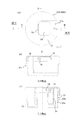
図1は、本発明に従うエアゾール容器用固定盤の第1実施形態を、容器に装着した状態で示す、(a)は平面図であり、(b)は側面図であって、図2は、図1(a)に示すA−Aに沿う要部拡大断面図であって、図3は、図1(a)に示すB−Bに沿う要部拡大半断面図であって、図4は、図1に示した固定盤につき、(a)は平面図であり、(b)は(a)のC−Cに沿う半断面図であり、(c)は(a)のD−Dに沿う断面図であり、(d)は下面図であって、図5は、図1に示した下カバーにつき、(a)は平面図であり、(b)は(a)のE−Eに沿う半断面図であり、(c)は(a)のF−Fに沿う断面図であって、図6は、図1に示した下カバーにつき、(a)は下面図であり、(b)は図5(a)の矢印Gに沿う矢視図であって、図7は、図1に示した上カバーにつき、(a)は平面図であり、(b)は(a)のH−Hに沿う断面図であり、(c)は(a)のI−Iに沿う半断面図であって、図8は、図1に示した上カバーにつき、(a)は下面図であり、(b)は図7(a)の矢印Jに沿う矢視図であり、(c)は図7(a)の矢印Kに沿う矢視図であって、図9は、図1に示したノズルの折り曲げ前の状態につき、(a)は平面図であり、(b)は(a)のL−Lに沿う断面図であり、(c)は(a)のM−Mに沿う半断面図であり、(d)は下面図であって、図10は、図2に示したオーバーキャップにつき、(a)は平面図であり、(b)は(a)のN−Nに沿う半断面図であり、(c)は(a)のO−Oに沿う断面図であって、図11は、図2に示したオーバーキャップにつき、(a)は下面図であり、(b)は図10(a)の矢印Pに沿う矢視図である。
なお、本明細書において前方とは、ノズルに設けた注出筒の出口側であり、後方とは、注出筒の軸線に沿って前方と反対側である。また、側方とは、前方から後方に向かって容器を見る際の左右方向である。
Hereinafter, the present invention will be described more specifically with reference to the drawings.
FIG. 1 shows a first embodiment of a fixed plate for an aerosol container according to the present invention in a state where it is mounted on a container, (a) is a plan view, (b) is a side view, and FIG. FIG. 3 is an enlarged cross-sectional view of main parts along AA shown in FIG. 1A, FIG. 3 is an enlarged half-sectional view of main parts along BB shown in FIG. 1A is a plan view, FIG. 1B is a half sectional view taken along the line CC of FIG. 1A, and FIG. 1C is a sectional view taken along the line DD of FIG. It is sectional drawing which follows, (d) is a bottom view, FIG. 5 is the bottom cover shown in FIG. 1, (a) is a top view, (b) is EE of (a). FIG. 6C is a cross-sectional view taken along the line FF of FIG. 6A, FIG. 6 is a bottom view of the lower cover shown in FIG. 1, and FIG. ) Is an arrow view along the arrow G in FIG. 7A is a plan view of the upper cover shown in FIG. 1, FIG. 7B is a cross-sectional view taken along line H-H in FIG. 7A, and FIG. FIGS. 8A and 8B are half cross-sectional views taken along line II, and FIG. 8A is a bottom view of the upper cover shown in FIG. 1, and FIG. 8B is an arrow view along arrow J in FIG. FIG. 9C is an arrow view along arrow K in FIG. 7A, FIG. 9 is a plan view of the state of the nozzle shown in FIG. 1 before bending, and FIG. (B) is sectional drawing which follows LL of (a), (c) is a half sectional view which follows MM of (a), (d) is a bottom view, FIG. FIG. 2A is a plan view of the overcap shown in FIG. 2, FIG. 2B is a half sectional view taken along line NN in FIG. 2A, and FIG. FIG. 11 is a cross-sectional view taken along the line A in FIG. Per over bar cap, (a) is a bottom view, is an arrow view along the arrow P of (b) FIGS 10 (a).
In addition, in this specification, the front is the exit side of the extraction tube provided in the nozzle, and the rear is the opposite side to the front along the axis of the extraction tube. Moreover, a side is the left-right direction at the time of seeing a container toward the back from the front.
図1〜図3において、符号10Aは、本発明に従うエアゾール容器用固定盤の第1実施形態であり、符号2は、固定盤10Aを装着するエアゾール容器である。また符号20Aは下カバーであり、符号30Aは上カバーであり、符号40Aはノズルであり、符号50Aはオーバーキャップ(図1ではオーバーキャップ50Aは省略)である。なお、下カバー20A及び上カバー30Aにてカバー部材60Aを構成している。
1 to 3,
エアゾール容器2は、図2に示すように、例えば金属製となる有底筒状の容器本体3に、例えば金属製となるマウンティングカップ4の外縁を巻き締めして(巻き締めした部位が環状縁部5となる)固着したものであり、内側には2種類の内容物が別個に収容されている。またエアゾール容器2は、それぞれの内容物の収容空間につながる総計2つのステム6を有していて、マウンティングカップ4の中央部には、平面視にてトラック状となる突起部7が、2つのステム6を一括りにして突出している。なお、突起部7の平面視での形状は、矩形状でも楕円状でもよい。
As shown in FIG. 2, the
固定盤10Aは、図2及び図3に示すように、2本のステム6を露出させる開口11を残してマウンティングカップ4に被さり、環状縁部5の上面に当接する外壁12を備えている。ここで外壁12は、図4(a)〜(d)に示すように、平面視が概略円形状となる有頂筒状の上段部12aと、上段部12aの下端より径方向外側に延在し、その外縁より垂下される中間段部12bと、中間段部12bの下端より径方向外側に延在し、その外縁より垂下される下段部12cとを備えている。また、上段部12aの中央部には、図4(c)に示すように、その内側に開口11を形成する内周壁12dを備えている。開口11は、図4(a)に示すように、平面視にて短辺が円弧状で長辺が直線状となる変形矩形状となるものであり、長辺が前方及び後方に位置する配置となっている。また本実施形態では、開口11の長辺が長く延びて、内周壁12dの一部が上段部12aの周壁と一体化している(図4(b)参照)。
As shown in FIGS. 2 and 3, the fixed plate 10 </ b> A includes an
また、図4(c)に示すように内周壁12dの下端には、その内周面に、図4(a)に示すように平面視にて内周面形状がトラック状となる位置決め壁13を設けている。なお、位置決め壁13の内周面形状は、エアゾール容器2の突起部7に対応するものであり、突起部7の形状に合わせて矩形状や楕円状のものが選択可能である。位置決め壁13の長辺側の縁部には、下方に向けて伸延する薄肉舌片14を設けている(本実施形態では総計2つ)。また、上段部12aには、スリット状の凹部15を設けていて、本実施形態では、前方に設ける凹部15の個数を、後方に設ける凹部15の個数に対して異なる数とするべく、図4(a)に示すように前方に2つ、後方に1つ設けている。なお、凹部15の個数は、前方に対して後方を増やすように(例えば前方に1つ、後方に2つ設ける)してもよい。また、図4(c)に示すように中間段部12bの裏面には、下方に向けて伸延する円筒壁16を設けていて、円筒壁16の内周面には、爪部(係合爪)16aを周方向に等間隔で総計3つ設けている。更に、中間段部12bと下段部12cとの境界には、図4(a)に示すようにその表裏を貫く穴(第1係合穴)17を、対向配置で総計2つ設けている。更に、中間段部12bと下段部12cとの境界には、図4(c)に示すように縦断面形状が三角状となる補強リブ18aを複数(本実施形態では総計10個)設けていて、第1係合穴17を挟む両側には、図4(b)に示すように補強リブ18aよりも高さが低くなる一対の小リブ(外面リブ)18bを設けている。
Further, as shown in FIG. 4C, a
また、本実施形態においては、固定盤10Aの剛性をより高めるべく、図4(d)に示すように、上段部12aの周壁内面と位置決め壁13とつなぐ補強リブ18c(本実施形態では総計6つ)と、上段部12aの周壁内面と内周壁12dとをつなぐ補強壁18d(本実施形態では総計4つ)を設けている。
Further, in the present embodiment, in order to further increase the rigidity of the fixed
下カバー20Aは、図5(a)〜(c)及び図6(a)〜(b)に示すように、平面視において、概略円板状をなすとともにその後方の一部を径方向外側に向けて突出させた形状となる天壁21(突出させた部位を突出部21aと称す)と、天壁21の縁部につながる周壁22を備えている。また周壁22は、後方を除いた下端において、天壁21よりも低い位置で水平方向に延在する連結壁23を介して外周壁24と連結している。また、天壁21は、前方及び後方において段部21bを備えるとともに、側方において一対の上部周壁21cを備えている。更に、天壁21の中央部には、平面視にて長辺が前方及び後方に位置する配置となり、短辺が円弧状で長辺が直線状となる変形矩形状の開口21dを設けている。
As shown in FIGS. 5 (a) to 5 (c) and FIGS. 6 (a) to 6 (b), the
また、図5(b)に示すように外周壁24の側方には、下方に向けて伸延する一対の第1係合片25を設けていて、第1係合片25には径方向外側を向く爪部25aを設けている。外周壁24の側方の上下方向中程には、薄肉状のヒンジhaを介して連結する一対の押圧部26を設けていて、その上部には外周壁24の表裏を貫く一対の穴(第2係合穴)27を設けている。また、外周壁24の内周面には、第2係合穴27の上方において傾斜部24aを設けている。更に、外周壁24の外周面には、第2係合穴27の上方において横向きに延在する凸部(カバー凸部)24b(本実施形態では、図5(a)に示すように各側方の前方及び後方にそれぞれ1つずつ、総計4つ)を設けている。
Further, as shown in FIG. 5B, a pair of
上カバー30Aは、図7(a)〜(c)及び図8(a)〜(b)に示すように、平面視において、概略円板状をなすとともにその後方の一部を切り欠き部31aで取り除いた形状となる天壁31と、天壁31の縁部につながる周壁32を備えている。周壁32は、前方においてその下方に切り欠き部32aを備えている(図8(b)参照)。また周壁32は、各側方に第2係合片33を備えていて、第2係合片33は、径方向外側を向く爪部33bを備えるとともに、爪部33bから下方に向けて延在させた押圧受部33aを備えている。また図7(a)に示すように、天壁31の切り欠き部31aには、薄肉状のヒンジhbを介して連結し、下方への押圧にてノズル40から内容物を吐出させる操作部34を設けている。なお、図示の例で操作部34の上面は、天面壁31の上面に対して略同一面上に位置しているが、操作部34の上面位置は、天面壁31の上面より下方側であっても、また、オーバーキャップ50を取り付けた際にノズル40を押し込まない程度で天面壁31の上面より上方側であってもよい。また、操作部34の上面は平坦状であるが、指当たりをよくするため、その中央部分を下向きに湾曲させもよい。また天壁31の裏面には、図7(c)に示すように内周壁35を設けている。
As shown in FIGS. 7A to 7C and FIGS. 8A to 8B, the
ノズル40Aは、図9(a)〜(d)に示すように、薄肉状のヒンジhcを介して上部部材41と下部部材45とを一体連結したものであり、ヒンジhcに沿って折り曲げることで、図2、図3に示す形態となるものである。
As shown in FIGS. 9A to 9D, the
上部部材41は、図9(a)に示すように、平面視が楕円状となる天壁41aと、天壁41aの縁部につながる周壁41bと、周壁41bの側方下端から外側に向けて延在するフランジ41cとを備えている。天壁41aには、側面視で半円状となる半円リブ41dを総計2つ設けている。また、上部部材41の前方には、横断面形状が概略矩形筒状となる注出筒42を一体連結している。更に上部部材41と注出筒42との連結部には、仕切壁43を設けている。また注出筒42の下方には爪部44を設けている。
As shown in FIG. 9 (a), the
下部部材45は概略平板状をなしていて、図9(b)に示すように、その後方に摘み部46を形成している。また下部部材45の表面には、円筒状の連結部47を総計2つ設けていて、裏面には、折り曲げた際に、周壁41bとの間で、連結部47から注出筒42の出口までつながる通路R(図3参照)を形成する環状壁48と、爪部44に係合して折り曲げ姿勢を維持する爪部49を設けている。
The
オーバーキャップ50Aは、図10(a)〜(c)及び図11(a)〜(b)に示すように、平面視において、概略円板状をなすとともにその前方の一部が段差をもって径方向外側に突出する天壁51と、天壁51の縁部につながる周壁52を備えている。また、周壁52の内周面には、径方向内側に向けて突出する凸部(キャップ凸部)53(本実施形態では各側方の前方及び後方にそれぞれ1つずつ、総計4つ)と、後方において間隔をあけて配置した一対の位置決めリブ54とを設けている。
As shown in FIGS. 10A to 10C and FIGS. 11A to 11B, the
次に、上記のような構成となる固定盤10A、下カバー20A、上カバー30A、ノズル40A、及びオーバーキャップ50Aに関し、図2、図3を参照して、これらをエアゾール容器2に装着する手順を説明する。
Next, with respect to the fixed
まず、固定盤10Aをマウンティングカップ4へ装着する。ここで、図4(a)に示す位置決め壁13のトラック形状の向きが、エアゾール容器2の突起部7の向きと合っている場合には、薄肉舌片14の先端が突起部7の下端に当接する高さまで固定盤10Aが下がることになるが、互いの向きがずれている場合には、薄肉舌片14の先端が突起部7の上面に当接して所定の高さよりも高い所に位置することとなる。すなわち、固定盤10Aの高さの違いで両者の向きが合っているか否かを判断することができるので、組み立て作業がより簡単になる。また、固定盤10Aを回転すると、両者の向きが合ったところで固定盤10Aが下方に移動するので、触覚をもって位置合わせの完了を知ることもできる。その後、固定盤10Aを押し込めば、図2に示すように薄肉舌片14は外側へ折れ曲がり、係合爪16aが環状縁部5に係合する。
First, the fixed platen 10 </ b> A is attached to the mounting
次いで、下カバー20Aの第1係合片25を固定盤10Aの第1係合穴17に位置合わせしつつ、下カバー20Aを固定盤10Aに押し込んで両者を係合させる。
Next, while the
その後、図9に示す状態から図2、図3に示す状態に折り曲げたノズル40Aを、注出筒42を前方に向けるようにして、エアゾール容器2のステム6に連結部47を嵌め合わせる。ここで、ノズル40Aは、図3に示すように下カバー20Aに設けた上部周壁21cの内側に配置されることになるが、上部周壁21cは、図5(a)に示すように前方の幅(La1)が後方の幅(Lb1)の幅よりも狭くなっており、同様に、ノズル40Aは、図9(a)に示すように前方の幅(La2)が後方の幅(Lb2)の幅よりも狭くなっていて、且つLb2>La1の関係を満たすように構成されているので、ノズル40Aを前後逆向きに取り付ける不具合が確実に防止できる。
Thereafter, the connecting
しかる後、上カバー30Aの第2係合片33を下カバー20Aの第2係合穴27に位置合わせしつつ、上カバー30Aを下カバー20Aに押し込んで両者を係合させる。ここで、図5(a)に示す下カバー20Aの突出部21aの幅(La3)に対し、上カバー30Aは、図7(a)に示す切り欠き部31aの幅(La4)は広く、図8(b)に示す切り欠き部32aの幅(La5)は狭くなっている(La4>La3>La5)。これにより、上カバー30Aを前後逆向きに取り付けようとしても、上カバー30Aの周壁32が下カバー20Aの突出部21aに当たり装着することができないので、所期した向きに確実に取り付けることができる。また、本実施形態では、図3に示すように第2係合穴27の上方に傾斜部24aを設けているので、第2係合片33は、挿入途中でスムーズに径方向内側に撓むこととなり、より小さい押し込み力で装着することができる。また、上カバー30Aを装着するに当たっては、内周壁35を、下カバー20Aの上部周壁21cに沿わせることができるので、内周壁35及び上部周壁21cが装着時のガイドとして機能する。
Thereafter, while aligning the
その後、オーバーキャップ50Aを上カバー30A上に取り付ける。ここで、図3に示すようにオーバーキャップ50Aのキャップ凸部53は、下カバー20Aのカバー凸部24bに係合し、オーバーキャップ50Aの裏面に設けた位置決めリブ54は、上カバー30Aの天壁31に設けた切り欠き部31aに入り込むので、オーバーキャップ50Aは所定の位置で保持される。前述のようにカバー凸部24b及びキャップ凸部53は、各側方の前方及び後方にそれぞれ1つずつ設けられているので、オーバーキャップ50Aは、前方、後方及び側方への傾きが抑えられ、より安定的に保持される。なお、カバー凸部は、上カバー30Aに設けてもよい。
Thereafter, the
なお、エアゾール容器2に固定盤10A等を取り付けるに当たっては、予め固定盤10Aに対して、下カバー20A、ノズル40A、上カバー30A、オーバーキャップ50Aを順に取り付けておき、これをエアゾール容器2に取り付けることも可能である。また、固定盤10Aから上カバー30Aまで組み立てた後、これをエアゾール容器2に取り付け、しかる後にオーバーキャップ50Aを取り付けてもよい。
When attaching the fixed
このようにして各部材を組み付けたエアゾール容器2から内容物を吐出させるには、まずオーバーキャップ50Aを取り外す。その後、上カバー30Aの操作部34を下方に向けて押し込むと、操作部34がノズル40Aの半円リブ41dに押し当たり、ノズル40Aにつながるステム6を押し下げる。これにより、2種類の内容物はそれぞれのステム6から同時に噴出され、ノズル40Aの内側に形成される通路Rを通して注出筒42の出口から吐出される。本実施形態において、ノズル40A内に設けた仕切壁43は、通路Rの上流側(通路Rのステム6側を上流側といい、注出筒の出口側を下流側という)のみを2つに区画しているが、内容物の種類によっては、仕切壁43を注出筒42の出口付近まで伸延させて通路Rの略全域を区画領域としても(すなわち、1つの注出筒42の内側に2つの通路部分が形成される)、また、上流側に向けて短くして本実施形態よりも区画領域を狭めても、更には、仕切壁43を取り除いて区画領域を省いてもよい。
In order to discharge the contents from the
また、通路R内に内容物が残留すると、乾燥して目詰まりの原因になるおそれがある。本実施形態では、下カバー20Aの押圧部26を径方向内側に押し込めば、図3に示すように、押圧部26の裏面が上カバー30Aの押圧受部33aに押し当たって、上カバー30Aの第2係合片33と下カバー20Aの第2係合穴27との係合が解除され、上カバー30Aを取り外すことが可能になる。その後、図2に示すように、ノズル40Aを上方に引き上げてステム6から取り外し、摘み部46を連結部47に向けて傾倒させれば爪部44と爪部49との係合が外れてノズル40Aを開くことができるので、ノズル40Aの内側を簡単に洗浄することができる。なお、摘み部46は、図示した形態に限られず、ノズル40を開く際に指掛かりとなるものであればどのようなものでもよい。
In addition, if the contents remain in the passage R, the contents may dry out and cause clogging. In this embodiment, if the
次に、図12〜図14を参照して、上述の実施形態に対して異なる種類のカバー部材、ノズル、オーバーキャップを装着した形態について説明する。なお上述した構成と共通のものについては、同一の符号を付して説明を省略する。 Next, with reference to FIG. 12 to FIG. 14, a mode in which different types of cover members, nozzles, and overcaps are attached to the above-described embodiment will be described. In addition, about the same thing as the structure mentioned above, the same code | symbol is attached | subjected and description is abbreviate | omitted.
カバー部材60Bは、概略、下カバー20Aと上カバー30Aとを一体化した機能を有するものであり、後方を切り欠いたドーム状の周壁61Bを備えていて、その切り欠きにヒンジhdを介して操作部62Bを設けている。周壁61Bの内側には、水平方向に延在し、固定盤10Aに設けた上段部12aの上面に当接する中間壁63Bを設けていて、中間壁63Bの中央部には、ステム6が挿通する開口を設けている。また、図12に示すように中間壁63Bの下面には、カバー部材60Bを固定盤10Aに取り付ける際に、固定盤10Aに設けたスリット状の凹部15内に嵌まり込む板状の凸部64Bを設けている。本実施形態においては、凹部15に対応させて前方に2つ、後方に1つ設けている。これにより、凸部64Bの数を手掛かりにカバー部材60Bの前後の向きを知ることができる上、カバー部材60Bを前後逆向きに取り付ける不具合が防止できる。なお、凹部15と凸部64Bとを相互に入れ換えて、固定盤10Aに凸部を設け、カバー部材60Bに凹部を設けてもよい。また、図13に示すように周壁61Bには、下方に向けて伸延する一対の第1係合片65Bを設けていて、第1係合片65Bには径方向外側を向く爪部65B1を設けている。なお、図14に示すように、第1係合片65Bの両側は、上下方向に延びるスリット66Bにて周壁61Bから分離されていて、外側から押し込むことで内側へ撓むので、固定盤10Aからカバー部材60Bを取り外すことができる。
The
ここで、図14に示すように周壁61Bの内面には、第1係合片65Bの両側に一対の内面リブ67Bを設けている。一対の内面リブ67Bは、固定盤10Aに設けた一対の外面リブ18b(図4(a)を参照)に挟まれる位置に設けられている。これにより、第1係合片65Bを押し込んでも、周壁61Bの内面リブ67Bが外面リブ18bに当接し、周壁61Bが潰れるようにして外側へ撓む変形が抑えられるので、カバー部材60Bを容易に取り外すことができる。
Here, as shown in FIG. 14, on the inner surface of the
また、図12、図13に示すようにノズル40Bは、概略、ノズル40Aの開閉機能を省略したものであり、ステム6につながる2つの連結部41Bと、内容物の出口となる1つの注出筒42Bとを一体連結し、その内側に内容物の通路Rを備えている。また、通路Rには、仕切壁43Bを設けている。更に、ノズル40Aの上部には、内容物を吐出する際に操作部62Bが押し当たる半円リブ44Bを設けている。
Moreover, as shown in FIGS. 12 and 13, the
オーバーキャップ50Bは、円板状の頂壁51Bの外縁に、上方から下方に向けて径方向内側に漸減する外面形状をなす外周壁52Bを一体連結したものであり、ノズル40Bの注出筒42Bをその内側に収めている。これにより、注出筒42Bに埃等が付着し難くなる。
The
次に、図15、図16を参照して、本発明に従うエアゾール容器用固定盤の第2実施形態について説明する。 Next, with reference to FIG. 15, FIG. 16, 2nd Embodiment of the stationary platen for aerosol containers according to this invention is described.
固定盤10Bは、概略、固定盤10Aと同形状であるが、図16に示すように中間段部12bの周壁外面に、内側へ撓むように形成された係合片11Bを設けている。また、係合片11Bは、径方向外側を向く爪部11B1を備えるとともにその先端を上方に向けて延在させた押圧受部12Bを備えている。
The fixed
カバー部材60Cは、カバー部材60Bと同様に、下カバー20Aと上カバー30Aとを一体化した機能を有するものであり、後方に切り欠きを有する角張ったドーム状の周壁61Cを備えていて、その切り欠きにヒンジheを介して操作部62Cを設けている。周壁61Cの内側には、固定盤10Bの上段部12aに被さる内側壁63Cを設けていて、内側壁63Cの中央部には、ステム6が挿通する開口を設けている。また、図16に示すように周壁61Cの側方には、ヒンジhfを介して押圧部64Cを設けていて、押圧部64Cの下方には、係合片11Bの爪部11B1が係合する係合穴65Cを設けている。これにより、カバー部材60Cは固定盤10Bに抜け止め保持される一方、押圧部64Cを内側に押し込めば、その裏面が押圧受部12Bに押し当たって係合片11Bの爪部11B1と係合穴65Cとの係合が解除され、カバー部材60Cを取り外すことができる。
Similar to the
ノズル40Cは、ステム6につながる2つの連結部41Cと、各連結部にそれぞれつながる2つの注出筒42Cとを一体連結し、その内側にそれぞれが独立した内容物の通路Rを備えている(通路Rは総計2つ)。連結部41Cの下端には、内側壁63Cの開口縁部に係合する爪部43Cを設けていて、カバー部材60Cに対してノズル40Cを抜け止め保持している。なお、上述した操作部62Cの裏面には、先端が円弧状となるリブ66Cを設けていて、操作部62Cを押圧すると、リブ66Cがノズル40Cの上面に押し当たり、それぞれのステム6から内容物が同時に吐出される。
The
次に、図17、図18を参照して、本発明に従う固定盤の第3実施形態について説明する。 Next, with reference to FIG. 17, FIG. 18, 3rd Embodiment of the stationary platen according to this invention is described.
固定盤10B’は、概略、固定盤10Bと同形状であるが、図17に示すように下段部12c’の周壁は、エアゾール容器2の外周面よりも径方向内側に寄っていて、更に、図18に示すように外向きの爪部11Cを備えている。
The fixed
カバー部材60C’は、概略、カバー部材60Cと同形状であるが、図17に示すように周壁61C’は、固定盤10B’の下段部12c’を内側に収めてエアゾール容器2の外周面と略同径の外形を有している。これにより、固定盤10B’全体がカバー部材60C’によって覆われることになるので、固定盤10B’に特別な装飾効果を施す必要がなくなる。また、周壁61C’の側面には、図18に示すように、爪部11Cに係合する係合穴67Cを形成した揺動片68Cを設けている。ここで揺動片68Cは、図中破線で示す連結片69Cによって前方及び後方で周壁61C’に連結するものであり、連結片69Cよりも上方に位置する揺動片68Cの上部域を内側に押圧すれば、揺動片68Cは連結片69Cを中心に揺動し、係合穴67Cが外側に変位して爪部11Cとの係合が解除される。
The
このように、本発明に従う固定盤は、主要部分は変更すること無く種々のカバー部材を取り付けることが可能であるため、開発効率が高まる上、コストを抑制することができる。 As described above, since the fixing plate according to the present invention can be attached with various cover members without changing the main part, the development efficiency is increased and the cost can be suppressed.
本発明によれば、2つのステムを有するエアゾール容器に対して確実かつ簡単に装着可能であり、また、種々のカバー部材を取り付けることができる新たなエアゾール容器用固定盤を提供できる。 ADVANTAGE OF THE INVENTION According to this invention, it can mount reliably and easily with respect to the aerosol container which has two stems, Moreover, the new stationary plate for aerosol containers which can attach various cover members can be provided.
2 エアゾール容器
4 マウンティングカップ
5 環状縁部
6 ステム
7 突起部
10A、10B、10B’ 固定盤
11 開口
12 外壁
13 位置決め壁
14 薄肉舌片
15 凹部
16 円筒壁
16a 係合爪
18b 小リブ(外面リブ)
20A 下カバー(カバー部材)
25 第1係合片
25a 爪部
27 第2係合穴
30A 上カバー(カバー部材)
33 第2係合片
33a 押圧受部
33b 爪部
40A、40B、40C ノズル
50A、50B オーバーキャップ
60A、60B、60C、60C’カバー部材
64B 凸部
65B 第1係合片(係合片)
65B1 爪部
67B 内面リブ
DESCRIPTION OF
20A Lower cover (cover member)
25
33
65B 1 claw 67B Internal rib
Claims (6)
前記2つのステムを露出させる開口を残して前記マウンティングカップに被さり、該マウンティングカップの環状縁部の上面に当接する外壁と、該外壁の下面において一体連結し該環状縁部を取り囲む円筒壁と、該円筒壁の内周面に設けられ該環状縁部に係合して該固定盤を抜け止め保持する係合爪とを備え、
前記外壁は、前記2つのステムを一括りにして前記マウンティングカップから突出し横断面形状が長辺及び短辺を有する異形状となる突起部に対し、その外周面に沿う内周面形状となる位置決め壁を備えるエアゾール容器用固定盤。 An aerosol container fixing plate that is mounted on an aerosol container having two stems and engages and holds a cover member that covers and hides the mounting cup of the container,
An outer wall that covers the mounting cup leaving an opening that exposes the two stems, abuts against the upper surface of the annular edge of the mounting cup, and a cylindrical wall that is integrally connected to the lower surface of the outer wall and surrounds the annular edge; An engagement claw provided on the inner peripheral surface of the cylindrical wall and engaged with the annular edge to prevent the fixing plate from being pulled out,
The outer wall protrudes from the mounting cup with the two stems as a whole and is positioned so as to have an inner peripheral surface shape along the outer peripheral surface thereof with respect to a protruding portion having a cross-sectional shape having a long side and a short side. Fixed plate for aerosol containers with walls.
Priority Applications (10)
| Application Number | Priority Date | Filing Date | Title |
|---|---|---|---|
| JP2013077931A JP5901564B2 (en) | 2013-04-03 | 2013-04-03 | Fixed plate for aerosol container |
| DE202013012140.8U DE202013012140U1 (en) | 2013-04-03 | 2013-11-13 | Aerosol-fixing |
| CN201380075204.5A CN105636880B (en) | 2013-04-03 | 2013-11-13 | Automiser spray fixed disk |
| PT138809918T PT2982615T (en) | 2013-04-03 | 2013-11-13 | Fixing plate for an aerosol container |
| BR112015023478-0A BR112015023478B1 (en) | 2013-04-03 | 2013-11-13 | attachment plate for an aerosol container |
| EP13880991.8A EP2982615B1 (en) | 2013-04-03 | 2013-11-13 | Fixing plate for an aerosol container |
| KR1020157029426A KR101820757B1 (en) | 2013-04-03 | 2013-11-13 | Aerosol-container fixed plate |
| ES13880991.8T ES2678195T3 (en) | 2013-04-03 | 2013-11-13 | Fixing plate for an aerosol container |
| PCT/JP2013/080702 WO2014162629A1 (en) | 2013-04-03 | 2013-11-13 | Aerosol-container fixed plate |
| US14/716,497 US9737902B2 (en) | 2013-04-03 | 2015-05-19 | Aerosol container fixing plate |
Applications Claiming Priority (1)
| Application Number | Priority Date | Filing Date | Title |
|---|---|---|---|
| JP2013077931A JP5901564B2 (en) | 2013-04-03 | 2013-04-03 | Fixed plate for aerosol container |
Publications (3)
| Publication Number | Publication Date |
|---|---|
| JP2014201329A JP2014201329A (en) | 2014-10-27 |
| JP2014201329A5 JP2014201329A5 (en) | 2015-02-26 |
| JP5901564B2 true JP5901564B2 (en) | 2016-04-13 |
Family
ID=51657949
Family Applications (1)
| Application Number | Title | Priority Date | Filing Date |
|---|---|---|---|
| JP2013077931A Active JP5901564B2 (en) | 2013-04-03 | 2013-04-03 | Fixed plate for aerosol container |
Country Status (10)
| Country | Link |
|---|---|
| US (1) | US9737902B2 (en) |
| EP (1) | EP2982615B1 (en) |
| JP (1) | JP5901564B2 (en) |
| KR (1) | KR101820757B1 (en) |
| CN (1) | CN105636880B (en) |
| BR (1) | BR112015023478B1 (en) |
| DE (1) | DE202013012140U1 (en) |
| ES (1) | ES2678195T3 (en) |
| PT (1) | PT2982615T (en) |
| WO (1) | WO2014162629A1 (en) |
Families Citing this family (8)
| Publication number | Priority date | Publication date | Assignee | Title |
|---|---|---|---|---|
| JP5901565B2 (en) | 2013-04-03 | 2016-04-13 | 東洋エアゾール工業株式会社 | Dispenser for aerosol containers |
| JP5901564B2 (en) * | 2013-04-03 | 2016-04-13 | 東洋エアゾール工業株式会社 | Fixed plate for aerosol container |
| EP3006373B1 (en) * | 2013-05-31 | 2017-09-06 | Toyo Aerosol Industry Co., Ltd. | Shoulder cover for aerosol container |
| WO2016208488A1 (en) * | 2015-06-23 | 2016-12-29 | 株式会社三谷バルブ | Adapter for exterior parts of mounting cup, aerosol spray mechanism, and aerosol product |
| BR112018008859B1 (en) | 2016-01-18 | 2022-02-01 | Toyo Aerosol Industry Co., Ltd | Fixing plate for aerosol container |
| JP6932626B2 (en) * | 2017-09-15 | 2021-09-08 | 株式会社マンダム | Nozzle unit and two-component discharger equipped with it |
| FR3092091B1 (en) | 2019-01-25 | 2021-08-13 | Lindal France | Diffuser for pressure vessel |
| JP6755632B2 (en) * | 2019-04-04 | 2020-09-16 | 株式会社吉野工業所 | Actuator for dual aerosol |
Family Cites Families (39)
| Publication number | Priority date | Publication date | Assignee | Title |
|---|---|---|---|---|
| US3156382A (en) * | 1962-08-17 | 1964-11-10 | W R Frank Packaging Engineers | Aerosol container adapter collar |
| US3180531A (en) * | 1964-02-18 | 1965-04-27 | Risdon Mfg Co | Overcap and actuating button for aerosol containers |
| US3333744A (en) * | 1965-10-22 | 1967-08-01 | Peter J Nilsen | Valve and nozzle construction for aerosol whipped cream dispenser |
| US3946912A (en) * | 1975-01-02 | 1976-03-30 | Emanuel Landsman | Actuator cap for aerosol dispenser |
| ZA764611B (en) * | 1976-07-30 | 1977-07-27 | A Almouli | Aerosol dispenser particularly useful as a pocket fire extinguisher |
| JPS6041340U (en) * | 1983-08-31 | 1985-03-23 | 凸版印刷株式会社 | Overcap for dispenser |
| FR2603558B1 (en) * | 1986-09-04 | 1988-11-18 | Oreal | DISPENSING HEAD OF A PASTY PRODUCT RESULTING FROM THE MIXTURE OF TWO SEPARATELY STORED COMPONENTS AND PACKAGING ASSEMBLY WITH SUCH A DISPENSING HEAD |
| DE19541594A1 (en) * | 1995-11-08 | 1997-05-15 | Pfeiffer Erich Gmbh & Co Kg | Discharge unit for media |
| FR2748406B1 (en) * | 1996-05-07 | 1998-08-28 | Valois | FIXED SPRAY DISPENSING DEVICE |
| US6736288B1 (en) * | 2000-10-26 | 2004-05-18 | Ronald D. Green | Multi-valve delivery system |
| FR2815616B1 (en) * | 2000-10-20 | 2003-01-24 | Oreal | DISTRIBUTION ASSEMBLY FOR THE EXTEMPORARY DISTRIBUTION OF TWO PRODUCTS |
| JP2002193363A (en) * | 2000-12-22 | 2002-07-10 | Maruichi Valve Co Ltd | Aerosol valve device for plurality of kinds of liquid |
| US6454139B1 (en) * | 2001-02-14 | 2002-09-24 | Precision Valve Corporation | Preassembled aerosol actuator assembly for in-line capping to an aerosol container |
| WO2003002426A1 (en) * | 2001-06-27 | 2003-01-09 | Kanebo,Limited | Mixer/extractor |
| US6691898B2 (en) * | 2002-02-27 | 2004-02-17 | Fomo Products, Inc. | Push button foam dispensing device |
| JP4243984B2 (en) * | 2003-07-25 | 2009-03-25 | 株式会社マンダム | Dual aerosol liquid ejection container |
| US7854350B2 (en) * | 2004-09-30 | 2010-12-21 | L'oreal | Distribution assembly intended for contemporaneous distribution of two products |
| US7845518B2 (en) * | 2005-08-25 | 2010-12-07 | L'oreal | Product packaging and dispensing assembly |
| US7748568B2 (en) * | 2005-08-25 | 2010-07-06 | L'oreal | Packaging and dispensing assembly |
| JP5046328B2 (en) * | 2007-05-25 | 2012-10-10 | 株式会社三谷バルブ | Content discharge mechanism for multiple connected containers, and aerosol and pump-type products equipped with this content discharge mechanism |
| JP2009023684A (en) * | 2007-07-19 | 2009-02-05 | Eiji Mori | Coating spraying can |
| DE202010018319U1 (en) * | 2009-12-01 | 2015-07-14 | Toyo Aerosol Industry Co., Ltd. | Aerosol device for arranging a plurality of liquids |
| JP5413902B2 (en) * | 2009-12-18 | 2014-02-12 | 株式会社三谷バルブ | Content release single member of the connecting container and aerosol type product provided with this content release single member |
| US8376186B2 (en) * | 2010-03-17 | 2013-02-19 | Yonyu Plastics Co., Ltd. | Fluid dispenser device |
| US20110226812A1 (en) * | 2010-03-17 | 2011-09-22 | Yonyu Plastics Co., Ltd. | Fluid dispenser device |
| JP5401388B2 (en) * | 2010-03-31 | 2014-01-29 | 株式会社吉野工業所 | Double container |
| WO2012007843A2 (en) * | 2010-07-12 | 2012-01-19 | Foamix Ltd. | Apparatus and method for releasing a unit dose of content from a container |
| KR101410406B1 (en) * | 2010-07-20 | 2014-06-20 | 도요 에어로졸 고교 가부시키가이샤 | Multiple fluid dispensing aerosol device |
| JP5734594B2 (en) * | 2010-08-03 | 2015-06-17 | 東洋エアゾール工業株式会社 | Actuator for aerosol container |
| JP5674386B2 (en) * | 2010-08-31 | 2015-02-25 | ホーユー株式会社 | Two-component dispenser |
| KR101410408B1 (en) * | 2010-12-02 | 2014-06-20 | 도요 에어로졸 고교 가부시키가이샤 | Multiple liquid dispensing aerosol device |
| AU2011345795C1 (en) * | 2010-12-22 | 2016-12-15 | Daizo Corporation | Valve assembly and aerosol container equipped with same, and aerosol product and process for production thereof |
| KR101614340B1 (en) * | 2011-08-30 | 2016-04-21 | 도요 에어로졸 고교 가부시키가이샤 | Residual quantity reduction member |
| USD731312S1 (en) * | 2013-02-20 | 2015-06-09 | Toyo Aerosol Industry Co., Ltd. | Fixture for aerosol spray container |
| JP5901564B2 (en) * | 2013-04-03 | 2016-04-13 | 東洋エアゾール工業株式会社 | Fixed plate for aerosol container |
| JP5901565B2 (en) * | 2013-04-03 | 2016-04-13 | 東洋エアゾール工業株式会社 | Dispenser for aerosol containers |
| JP6151575B2 (en) * | 2013-05-31 | 2017-06-21 | 東洋エアゾール工業株式会社 | Nozzle for aerosol container and discharge tool for aerosol container |
| JP6161958B2 (en) * | 2013-05-31 | 2017-07-12 | 東洋エアゾール工業株式会社 | Nozzle cap for aerosol containers |
| EP3006373B1 (en) * | 2013-05-31 | 2017-09-06 | Toyo Aerosol Industry Co., Ltd. | Shoulder cover for aerosol container |
-
2013
- 2013-04-03 JP JP2013077931A patent/JP5901564B2/en active Active
- 2013-11-13 EP EP13880991.8A patent/EP2982615B1/en active Active
- 2013-11-13 BR BR112015023478-0A patent/BR112015023478B1/en active IP Right Grant
- 2013-11-13 ES ES13880991.8T patent/ES2678195T3/en active Active
- 2013-11-13 WO PCT/JP2013/080702 patent/WO2014162629A1/en active Application Filing
- 2013-11-13 PT PT138809918T patent/PT2982615T/en unknown
- 2013-11-13 CN CN201380075204.5A patent/CN105636880B/en active Active
- 2013-11-13 DE DE202013012140.8U patent/DE202013012140U1/en not_active Expired - Lifetime
- 2013-11-13 KR KR1020157029426A patent/KR101820757B1/en active IP Right Grant
-
2015
- 2015-05-19 US US14/716,497 patent/US9737902B2/en active Active
Also Published As
| Publication number | Publication date |
|---|---|
| US20150251202A1 (en) | 2015-09-10 |
| EP2982615B1 (en) | 2018-05-30 |
| WO2014162629A1 (en) | 2014-10-09 |
| EP2982615A1 (en) | 2016-02-10 |
| CN105636880A (en) | 2016-06-01 |
| CN105636880B (en) | 2017-10-20 |
| BR112015023478B1 (en) | 2021-05-11 |
| PT2982615T (en) | 2018-06-29 |
| US9737902B2 (en) | 2017-08-22 |
| BR112015023478A2 (en) | 2017-07-18 |
| KR20150130538A (en) | 2015-11-23 |
| EP2982615A4 (en) | 2017-02-08 |
| DE202013012140U1 (en) | 2015-05-06 |
| ES2678195T3 (en) | 2018-08-09 |
| JP2014201329A (en) | 2014-10-27 |
| KR101820757B1 (en) | 2018-01-22 |
Similar Documents
| Publication | Publication Date | Title |
|---|---|---|
| JP5901564B2 (en) | Fixed plate for aerosol container | |
| JP5901565B2 (en) | Dispenser for aerosol containers | |
| JP2011213400A (en) | Twin container | |
| JP6126917B2 (en) | Multiple container | |
| JP2017030801A (en) | Discharge tool | |
| JP5658999B2 (en) | Injection device | |
| JP6576147B2 (en) | Dispensing tool | |
| JP6362849B2 (en) | Actuator for aerosol container | |
| WO2014192621A1 (en) | Shoulder cover for aerosol container | |
| JP6180885B2 (en) | Aerosol shoulder cover | |
| JP6584364B2 (en) | Dispensing tool | |
| JP6599177B2 (en) | Dispensing tool | |
| JP6258118B2 (en) | Dispenser for aerosol containers | |
| JP2014234197A (en) | Shoulder cover for aerosol container | |
| JP2018122895A (en) | Discharge tool for aerosol container | |
| JP6866013B2 (en) | Discharger for aerosol container | |
| JP6656951B2 (en) | Discharge container | |
| JP6223925B2 (en) | Aerosol shoulder cover | |
| JP4684091B2 (en) | Aerosol container cap | |
| JP2019182538A (en) | Discharge member | |
| JP2007176586A (en) | Over-cap for aerosol container | |
| JP2001048256A (en) | Container cover and container with container cover | |
| JP2002264956A (en) | Mounting cup cover of aerosol vessel | |
| JP2014234198A (en) | Shoulder cover for aerosol container | |
| JP2009143624A (en) | Aerosol container cap with degassing function |
Legal Events
| Date | Code | Title | Description |
|---|---|---|---|
| A521 | Request for written amendment filed |
Free format text: JAPANESE INTERMEDIATE CODE: A523 Effective date: 20150109 |
|
| A131 | Notification of reasons for refusal |
Free format text: JAPANESE INTERMEDIATE CODE: A131 Effective date: 20150825 |
|
| TRDD | Decision of grant or rejection written | ||
| A01 | Written decision to grant a patent or to grant a registration (utility model) |
Free format text: JAPANESE INTERMEDIATE CODE: A01 Effective date: 20160216 |
|
| A61 | First payment of annual fees (during grant procedure) |
Free format text: JAPANESE INTERMEDIATE CODE: A61 Effective date: 20160308 |
|
| R150 | Certificate of patent or registration of utility model |
Ref document number: 5901564 Country of ref document: JP Free format text: JAPANESE INTERMEDIATE CODE: R150 |
|
| R250 | Receipt of annual fees |
Free format text: JAPANESE INTERMEDIATE CODE: R250 |
|
| R250 | Receipt of annual fees |
Free format text: JAPANESE INTERMEDIATE CODE: R250 |
|
| R250 | Receipt of annual fees |
Free format text: JAPANESE INTERMEDIATE CODE: R250 |
|
| R250 | Receipt of annual fees |
Free format text: JAPANESE INTERMEDIATE CODE: R250 |
|
| R250 | Receipt of annual fees |
Free format text: JAPANESE INTERMEDIATE CODE: R250 |
|
| R250 | Receipt of annual fees |
Free format text: JAPANESE INTERMEDIATE CODE: R250 |