EP3914510B2 - Flügelrigg - Google Patents
Flügelrigg Download PDFInfo
- Publication number
- EP3914510B2 EP3914510B2 EP20701589.2A EP20701589A EP3914510B2 EP 3914510 B2 EP3914510 B2 EP 3914510B2 EP 20701589 A EP20701589 A EP 20701589A EP 3914510 B2 EP3914510 B2 EP 3914510B2
- Authority
- EP
- European Patent Office
- Prior art keywords
- leading edge
- boom
- wing rig
- wing
- canopy
- Prior art date
- Legal status (The legal status is an assumption and is not a legal conclusion. Google has not performed a legal analysis and makes no representation as to the accuracy of the status listed.)
- Active
Links
Images
Classifications
-
- B—PERFORMING OPERATIONS; TRANSPORTING
- B63—SHIPS OR OTHER WATERBORNE VESSELS; RELATED EQUIPMENT
- B63H—MARINE PROPULSION OR STEERING
- B63H8/00—Sail or rigging arrangements specially adapted for water sports boards, e.g. for windsurfing or kitesurfing
- B63H8/10—Kite-sails; Kite-wings; Control thereof; Safety means therefor
-
- B—PERFORMING OPERATIONS; TRANSPORTING
- B63—SHIPS OR OTHER WATERBORNE VESSELS; RELATED EQUIPMENT
- B63H—MARINE PROPULSION OR STEERING
- B63H9/00—Marine propulsion provided directly by wind power
- B63H9/04—Marine propulsion provided directly by wind power using sails or like wind-catching surfaces
- B63H9/06—Types of sail; Constructional features of sails; Arrangements thereof on vessels
- B63H9/067—Sails characterised by their construction or manufacturing process
-
- B—PERFORMING OPERATIONS; TRANSPORTING
- B63—SHIPS OR OTHER WATERBORNE VESSELS; RELATED EQUIPMENT
- B63H—MARINE PROPULSION OR STEERING
- B63H8/00—Sail or rigging arrangements specially adapted for water sports boards, e.g. for windsurfing or kitesurfing
- B63H8/10—Kite-sails; Kite-wings; Control thereof; Safety means therefor
- B63H8/16—Control arrangements, e.g. control bars or control lines
-
- B—PERFORMING OPERATIONS; TRANSPORTING
- B63—SHIPS OR OTHER WATERBORNE VESSELS; RELATED EQUIPMENT
- B63H—MARINE PROPULSION OR STEERING
- B63H8/00—Sail or rigging arrangements specially adapted for water sports boards, e.g. for windsurfing or kitesurfing
- B63H8/10—Kite-sails; Kite-wings; Control thereof; Safety means therefor
- B63H8/12—Kites with inflatable closed compartments
Definitions
- the invention relates to a hand-supported wing rig for foil surfing, wind skating or skiing according to the preamble of patent claim 1.
- Such a wing rig is described online under the name "Slingwing.” It is essentially a kite with a leading edge and a single inflatable strut. The center strut and the leading edge each have straps that allow the user to hold the inflatable wing rig during foiling, ice skating, or skiing.
- This inflatable wing rig which is adapted to the aerodynamics of kites, is severely deformed during use, especially at the high speeds reached during foiling, thus worsening the aerodynamics.
- a rigid wing rig is shown in which the leading edge and boom are formed by a complex tubular structure that spans a sailcloth (canopy).
- the leading edge is curved in a plan view.
- the boom is supported by a plurality of struts on the leading edge. These struts are designed in such a way that, when viewed from the front—i.e., in the direction of the wing rig's airflow—they give the leading edge a concave structure, according to which the end sections (tips) of the wing rig flare upwards from a central apex of the leading edge.
- a disadvantage of this solution is that the complex structure of the boom and leading edge results in a very high overall weight of the wing rig, making its use in water sports only possible with appropriate buoyancy aids.
- Another disadvantage is that setting up and dismantling the wing rig is time-consuming due to the complex tubular structure. This hard tubular structure of the leading edge and boom also poses a significant risk of injury to the user in the event of a catastrophic fall.
- the EP1151918A1 shows a hang glider with ropes attached to a mat that inflates itself during flight.
- the pilot controls the hang glider using a rope system.
- the DE3421503A1 shows a lightweight wing for hang gliders, ultralight vehicles, whose leading edge is supported by an air cushion.
- the invention is based on the object of creating a hand-supported wing rig that allows for simple assembly and maintains an aerodynamically optimized profile even at high speeds.
- the tree is preferably designed with a sheath that improves grip/friction.
- the approximately V- or U-shaped profile extends from the leading edge toward the trailing edge of the canopy. This means that the entire wing rig profile is profiled to open upwards when viewed from the front (in the direction of flow).
- the efficiency of the wing rig is further improved when the V- or U-angle is maximum in the boom attachment area and decreases towards the tips. It is preferred if the angle of inclination to the horizontal (parallel to the connecting line through the tips) in the apex area is between 10° and 30°, preferably more than 15°, and particularly preferably approximately 20°.
- the "angle of inclination” is understood to be the angle that the respective area of the leading edge assumes when the wing rig is positioned parallel to the water surface/usable surface, i.e., to the horizontal.
- the opening angle between the mutually inclined leading edge areas then corresponds to the difference between 180° and twice the angle of inclination (supplementary angle to 180°).
- the trailing edge (leech) is designed with a corresponding profile angle.
- the aerodynamics are further improved if the inclination angle in the tip area is between 0° and 20°, preferably more than 1°, preferably about 5°.
- the wing rig is designed such that the average angle of inclination, i.e. the angle from the apex of the leading edge to the respective tip, is 5° to 20°, preferably about 10°.
- the boom can be telescopic or made up of several interchangeable sections.
- the technical effort required is particularly minimal if the boom is attached to the leading edge and the trailing edge using a bracket that can be interchangeably mounted. This allows a single boom to be used for multiple wing rigs.
- the flight stability of the wing rig is further improved if the boom mount is designed in such a way that it prevents rotation of the leading edge around its longitudinal axis.
- the holder encompasses the leading edge in sections and thus prevents rotation.
- the bracket can also extend through the leading edge.
- appropriate receptacles for the bracket or boom must be provided on the leading edge.
- a channel should be provided into which the bracket or boom can be inserted.
- the boom is unbraced. This solution is both weight-optimized and allows the user to adjust the boom and thus the wing rig to suit the maneuver and the environmental conditions.
- the center of gravity (center of canopy) is at least 30 percent, preferably more than 40 percent of the distance between the apex of the leading edge and the trailing edge (leech) from the leading edge.
- leading edge and/or the canopy can be stiffened using stiffening elements, such as sail battens.
- These sail battens can in turn be curved and/or tapered to profile the wing profile.
- a sail batten extends from the leading edge to the trailing edge, this sail batten being positioned such that it lies in a vertical plane with the boom (on the horizontal alignment of the wing rig).
- a handle can be provided in the connection area of the tree, preferably on the leading edge.
- the wing rig is equipped with a safety leash.
- the present application also discloses a wing rig with the above-described V- or U-shaped profile and a rigid, non-inflatable leading edge.
- the bracket for connecting the boom to the leading edge can, for example, be formed by a profile piece that surrounds the leading edge in sections and is attached to the leading edge via suitable fasteners. The boom is then inserted into the profile piece or connected to it in some other way.
- An alternative solution involves attaching a boom support to the leading edge using profiled parts or canvas. These profiled parts, in turn, surround the leading edge in sections, preventing the leading edge from rotating during use.
- the boom preferably extends from the leading edge to the trailing edge, without being directly or permanently connected to the canopy in the areas in between, so that virtually the entire boom length is available as a grip area. This ensures that the wing rig can be optimally held according to the user's preferences during any maneuver. Furthermore, the profile depth can be adjusted by adjusting the boom length.
- the structure of the wing rig is designed in such a way that in the flow-dependent state, i.e. when using the wing rig, the opening angle in particular in the trailing edge area.
- the profile depth can also increase in the flow-dependent state.
- the change in the opening angle can be greater in the tailing edge area than in the leading edge area.
- the tree is preferably attached to the area facing away from the canopy at the apex of the leading edge.
- the attachment is such that a lateral pivoting/adjustment of the wing rig is possible by rotating the boom around its longitudinal axis - this would not be possible with loops (handles), as these are not rigid and therefore no torque can be applied.
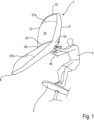
- FIG. 1 The use of a wing rig 1 according to the invention for propelling a foil board 2 is shown.
- a surfer 4 holds the wing rig 1 only with his hands and adjusts it with respect to the wind depending on the desired direction of travel (upwind, half wind, downwind) or the lift to be set, for example when jumping or adjusting the ride height.
- the wing rig 1 has an inflatable Leading Edge 6, which in plan view (from above into the Figures 1 and 2 ) is approximately arched, preferably approximately delta-, C- or U-shaped, and extends with its tips 8, 10 up to a trailing edge 12 of a canopy 14 of the wing rig 1.
- this canopy 14 is supported on the one hand by the leading edge 6 and on the other hand by a boom 16 which will be explained in more detail below (see Figure 3 ).
- the surfer 4 holds the wing rig 1 only by the boom 16, which is pointing downwards (view from Figure 1 ).
- the boom 16 is preferably provided with a sheath that simplifies/optimizes gripping and holding.
- leading edge 6 is designed both in plan view ( Figure 2 ) as well as in a front view - seen in the direction of flow - (see Figure 4 ) V- or U-shaped, with the V/U extending upwards in the front view, ie, away from the surfer. How Figure 1 removable, the trailing edge 12 and thus the entire canopy surface 14 is V-shaped in the front view.
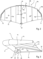
- Figure 2 shows a top view of the wing rig 1 according to Figure 1 .
- the leading edge 6 which is approximately arched or delta-shaped, essentially U- or C-shaped, and which extends to the trailing edge 12 of the canopy 14.
- the leading edge 6 is formed in the manner of a kite by a front tube in which a bladder is accommodated, which is inflated via a valve, the pressure being selected such that the structure of the wing rig 1 is guaranteed even at high wind speeds and at high speeds.
- the leading edge 6 is formed by a plurality of tube segments 18a, 18b, 18c, 18d, 18e (for the sake of simplicity, only one half of the trailing edge 12 is provided with reference numerals), the angle of attack ⁇ to the horizontal in Figure 2 , ie, for example, increases towards a connecting line between the two tips 8, 10 from a vertex 20 to the tips 8, 10.
- This angle of attack ⁇ is shown as an example for the tube segment 18a.
- the center of canopy is identified by reference number 22. This center of canopy 22 is offset from the vertex 20 by at least 40 percent of the distance between the vertex 20 and the corresponding vertex 24 of the trailing edge 12.
- the distance between the vertices 20, 24 is in Figure 2 marked with the reference symbol a. Accordingly, the distance b between the vertex 20 and the centroid 22 is at least 40 percent of the distance a.
- This center of gravity 22 is selected so that the surfer 4 can optimally grasp the boom 16, which will be explained in more detail below, and thus support the acting wind forces in order, for example, to sail an optimal upwind course.
- a central center batten 23 and two battens 27a, 27b are provided, which are offset towards the tips 8, 10 and extend between the leading edge 4 and the tailing edge 12 and are inserted into corresponding batten pockets of the canopy 14. This insertion takes place in a conventional manner with a certain pre-tension, which is selected according to the desired profile or can be changed to adapt the profile to different wind strengths.
- the reference numeral 29 denotes Figure 2 seams of the Canopy 14 are shown, which is composed of several panels It may also be sufficient to design the panels in such a way that, for example, they are only sewn in the area of the sail battens or run continuously from tip 8 to tip 10.
- the center batten 23 extends parallel to the longitudinal extent of the boom 16 between the leading edge 6 and the tailing edge 12. Accordingly, this batten 23 also engages on the one hand in the apex 20 of the leading edge 6 and on the other hand in the apex 24 of the trailing edge 12.
- the boom 16 and the center batten 23 thus lie in the same vertical plane, which in Figure 2 perpendicular to the plane of the drawing and in Figure 3 is in the plane of the drawing.
- the space between the boom and batten 23 / canopy 14 is thus free, allowing the surfer to freely choose his grip position depending on the maneuver/course.
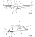
- the Leading Edge 6 can also be used perpendicular to the drawing plane in Figure 2 Specifically, the leading edge 6 is V-shaped from the apex 20 to the tips 8, 10, with the V (also called opening angle ⁇ ) - as in Figure 1 shown - upwards, ie, away from the tree 16. This V-profile is also formed accordingly in the area of the canopy 14. This is achieved, among other things, by the tree 16 reaching the apex 24 in the illustration according to Figure 3 downwards, i.e., away from the tips 8, 10, thus forming the V-shape determined by the opening angle ⁇ .
- the structure of the wing rig 1 is designed such that this opening angle ⁇ decreases when exposed to the flow, since the tips 8, 10 deflect upwards (away from the surfer 4) due to the load.
- the boom 16 thereby engages the area of the apex 20 of the leading edge 6 (located below) that is challenged by the canopy 14.
- the V-shape is particularly evident in the front view according to Figure 4 visible.
- the leading edge 6 formed by the tube is positioned facing the viewer.
- the canopy 14 is accordingly V-shaped.
- the angle of inclination ⁇ of the leading edge 6 is maximum in the area of the apex 20.
- this angle of inclination ⁇ i.e. the angle between the horizontal (parallel to the connecting line of the tips 8, 10) and the tube segment 18a, is approximately 20°, for example.
- the next tube segment 18b is then somewhat flatter, so that the angle is, for example, 15°.
- the angle of inclination of the following segments 18c, 18d, 18e is then again flatter, whereby the angle of inclination ⁇ in the area of segment 18c can be, for example, 5°.
- the "average" angle of inclination ⁇ seen over the entire wing rig 1 is, for example, 10°, so that the "average" opening angle is then approximately 160°.
- the boom 16 is designed without braces—this is a significant difference from the complex constructions described above, in which the boom is designed with a multitude of transverse and diagonal braces.
- the boom 16 can be releasably attached to the apex 20 of the leading edge 6 via a bracket 25.
- the holder 25 has a support bracket 26, which is configured to correspond to the outer contour of the apex 20 and encompasses it in sections. This encompassing occurs in such a way that, at comparatively high wind pressure, rotation of the tube, i.e., the tube segments 18a forming the apex 20, in the direction of the arrow, and thus twisting of the profile, is reliably prevented.
- a receptacle 28 Adjacent to the support bracket 26 in the direction of the boom 16 is a receptacle 28 into which the boom 16 is inserted.
- the end sections of the support bracket 26 and the receptacle 28 are connected via an arcuate handle 30, which makes it easier for the surfer 4 to handle the wing rig 1 before and after use.
- the wing rig 1 can be held by the handle 30 to allow it to blow away in the wind.
- the bracket 25 and the boom 16 are preferably made of a lightweight material, for example aluminum, fiber-reinforced plastic, carbon fiber materials, or other high-strength lightweight materials. Due to the simple structure of the boom 16, it has a negligible impact on the overall weight of the wing rig 1.
- Figure 5 shows a side view of a variant of the previously described embodiment of a wing rig 1.
- the view corresponds approximately to that of Figure 3 .
- the apex 24 of the trailing edge 12 is led downwards by the tree 16 (view to Figure 5
- the holder 25 of the tree 16 in turn has a receptacle 28 into which the tree 16 is inserted or which is otherwise connected to the tree 16.
- the apex 20 is supported according to Figure 6 at the top of the receptacle 28.
- a lightweight, approximately U-shaped handle 32 extends away from the receptacle 28, the end section of which engages the apex 20 formed by the tube segments 18a at a distance from the support of the apex 20 on the receptacle 28, i.e., offset towards the canopy 14.
- the handle 32 is designed as a truss structure.
- the connection of the receptacle 28 and the end section 34 to the apex can be achieved via suitable fixing elements on the tube segments 18a. These fixing elements are preferably designed such that the handle 30 is detachably connected to the leading edge 6 (front tube).
- the handle 32 which is more or less integrated into the tree structure, this can also be designed as a loop on the upstream side of the leading edge 6, so that the surfer can let the wing rig 1 blow out while holding it in his hand while surfing, for example.
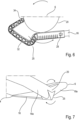
- Figure 7 shows an embodiment in which the holder 25 is designed as a flat body which is designed to encompass the trailing edge 6 or the tube segments 18a in sections.
- This flat holder can, for example, be designed as a molded body.
- the holder 25 is made of canvas, which is connected to the apex 20 of the leading edge 6 and, if necessary, stabilized by suitable stiffening elements. The boom 16 can then be inserted into this holder 25.
- the holder 25 is also designed such that rotation of the tube (leading edge 6) in the direction of the arrow is prevented by the support provided by the boom 16.
- the front tube is designed with a continuous bladder, as explained.
- a separate bladder is used for each half of the wing rig, with a gap between these two bladders as shown in Figure 8 a support channel 36 remains into which the boom 16 is inserted.
- This support channel 36 can, for example, be formed by a piece of pipe that passes diametrically through the front tube.
- This support channel 36 is formed between the two bladders of the two wing rig halves (left, right).
- a bearing ring 40 is formed on an outer shell 38 of the front tube (leading edge 6), which runs as an extension of the support channel 36 and through which the boom 16 passes.
- This bearing ring 40 absorbs the compression forces and is designed similarly to the support rings of the commonly used kite valves.
- a similar support ring 42 is provided opposite the bearing ring 40 on the inside of the outer shell 38, on which the Figure 8 The left end section of the boom 16 is supported.
- the tubular support channel 36 is connected to the bearing ring 40 on the one hand and the support ring 42 on the other, so that the boom 16 is reliably fixed in position.
- Such a solution has the advantage that the bearing rings 40 and the support rings 42 can be used for virtually any front tube diameter—only the length of the support channel 36 needs to be adjusted.
- the boom 16 is very stably supported, so that the holding forces introduced by the surfer 4 and the compression forces transmitted by the front tube are reliably absorbed without excessively deforming the boom 16.
- the support channel 36 and the rings 40, 42 are preferably designed as plastic injection-molded parts.
- the canopy 14 can be stabilized using sail battens or the like. These sail battens can be conical or profiled to optimize the airflow profile of the canopy 14. Similarly, the leading edge 16 can also be stiffened using suitable stiffening elements, so that the wing rig 1 maintains the aerodynamically optimized shape shown even under high loads.
- These sail battens or stiffening elements can also be designed as carbon fiber tubes or the like.
- the sail battens are profiled in such a way that they are first adapted to the diameter of the leading edge 6 (front tube) and then support the canopy 14.
- additional or alternative sail battens can be inserted into the canopy 14 from the trailing edge 12.
- wing rig 1 In order to prevent the wing rig 1 from drifting away in the event of a fall, it is connected to the surfer 4, in particular to his arm, via a safety leash 44.
- a hand-supported wing rig which is designed with an inflatable leading edge, which is designed in the direction of flow in an approximately V- or U-shaped manner and widens upwards (away from the surfer).
Landscapes
- Engineering & Computer Science (AREA)
- Chemical & Material Sciences (AREA)
- Combustion & Propulsion (AREA)
- Mechanical Engineering (AREA)
- Ocean & Marine Engineering (AREA)
- Sustainable Energy (AREA)
- Life Sciences & Earth Sciences (AREA)
- Sustainable Development (AREA)
- Manufacturing & Machinery (AREA)
- Toys (AREA)
- Wind Motors (AREA)
- Structures Of Non-Positive Displacement Pumps (AREA)
- Executing Machine-Instructions (AREA)
- Pyrane Compounds (AREA)
- Transition And Organic Metals Composition Catalysts For Addition Polymerization (AREA)
- Tents Or Canopies (AREA)
Description
- Die Erfindung betrifft ein handgestütztes Flügelrigg zum Foilsurfen, Windskaten oder Skifahren gemäß dem Oberbegriff des Patentanspruchs 1.
- Ein derartiges Flügelrigg wird unter dem Namen "Slingwing" im Internet beschrieben. Es handelt sich dabei im Prinzip um einen Kite mit einer Leading Edge und einer einzigen Strut, die aufblasbar (inflatable) ausgeführt sind. An der mittigen Strut und an der Leading Edge sind jeweils Halteschlaufen ausgebildet, über die der Nutzer das inflatable Flügelrigg während der Nutzung beim Foilen, oder beim Eisskaten oder beim Skifahren hält.
- Dieses an die Aerodynamik von Kites angepasste inflatable Flügelrigg wird während der Nutzung, insbesondere bei den beim Foilen erreichten hohen Geschwindigkeiten stark deformiert, und somit die Aerodynamik verschlechtert.
- In der
US 4,563,969 ist ein starres Flügelrigg gezeigt, bei dem die Leading Edge und ein Baum durch eine komplexe Rohrkonstruktion ausgebildet ist, die ein Segeltuch (Canopy) aufspannt. Die Leading Edge ist in einer Draufsicht gesehen bogenförmig gekrümmt. Der Baum ist durch eine Vielzahl von Streben an der Leading Edge abgestützt. Diese Streben sind derart ausgebildet, dass sie der Leading Edge in einer Vorderansicht, d. h., in Anströmrichtung des Flügelriggs gesehen - eine konkave Struktur verleihen, gemäß der die Endabschnitte (Tips) des Flügelriggs von einem mittigen Scheitel der Leading Edge aus nach oben ausgestellt sind. - Ein Nachteil dieser Lösung ist, dass durch den komplexen Aufbau des Baums und der Leading Edge das Gesamtgewicht des Flügelriggs sehr hoch ist, so dass eine Nutzung beim Wassersport nur mit entsprechenden Auftriebskörpern möglich ist. Ein weiterer Nachteil besteht darin, dass der Auf- und Abbau des Flügelriggs aufgrund der komplexen Rohrstruktur viel Zeit in Anspruch nimmt. Diese harte Rohrstruktur der Leading Edge und des Baums bringt auch eine erhebliche Verletzungsgefahr des Nutzers bei einem Schleudersturz mit sich.
- Ein ähnliches starres Flügelrigg ist in der
WO 95/05973 A1 US 4,563,969 . - In dem Dokument
US 5,448,961 ist ein ebenes Flügelrigg mit einer geschlossenen Rahmenstruktur beschrieben - eine derartige Lösung ist für den Wassersport aufgrund des hohen Gewichts, der zeitaufwendigen Montage/Demontage und der Verletzungsgefahr ebenfalls unbrauchbar. - Die
EP1151918A1 zeigt einen Hängegleiter mit Seilen, die an einer Matte befestigt sind, die sich während des Flugs selbstständig aufbläst. Der Pilot steuert den Hängegleiter über ein Seilsystem. - Die
DE3421503A1 zeigt einen Leichtbautragflügel für Hängegleiter, Ultraleicht-Fahrzeuge, dessen Anströmkante durch ein Luftkissen abgestützt ist. - Demgegenüber liegt der Erfindung die Aufgabe zugrunde, ein handgestütztes Flügelrigg zu schaffen, das einen einfachen Aufbau ermöglicht und auch bei hohen Fahrgeschwindigkeiten ein aerodynamisch optimiertes Profil beibehält.
- Diese Aufgabe wird durch ein handgestütztes Flügelrigg mit den Merkmalen des Patentanspruchs 1 gelöst.
- Vorteilhafte Weiterbildungen der Erfindung sind Gegenstand der Unteransprüche.
- Das erfindungsgemäße handgestützte Flügelrigg ist insbesondere für das Foilsurfen und die damit einhergehenden hohen Geschwindigkeiten geeignet. Das Flügelrigg hat eine, vorzugsweise inflatable ausgeführte, Leading Edge, von der sich ein Baum erstreckt, wobei die Leading Edge
und der Baum eine Canopy aufspannen. Das Flügelrigg wird während der Nutzung insbesondere am Baum gehalten. Die Leading Edge ist von einer Anbindung des Baums weg zum Achterliek (Trailing Edge) der Canopy hin in einer Draufsicht etwa bogenförmig, deltaförmig, U- oder C-förmig gekrümmt aufgeführt. Die Leading Edge ist des Weiteren im nicht angeströmten oder belasteten Zustand in einer in Anströmrichtung gesehenen Frontansicht etwa V- oder U-förmig ausgebildet, wobei dieses Profil zum Baum hin konvergiert. Mit anderen Worten gesagt, das Profil öffnet sich bei der Nutzung nach oben, weg vom Fahrer. Es zeigte sich überraschender Weise, dass sich durch eine derartige ausgeprägte V- oder U-Profilierung und die bogenförmige, deltaförmige oder U- bzw. C-förmige Ausgestaltung der Leading Edge (in einer Draufsicht gesehen) auch bei hohen Wind- und Fahrgeschwindigkeiten ein aerodynamisch optimiertes Profil einstellt, das sich zum einen bei Böen selbsttätig öffnet und somit den resultierenden, vom Nutzer abzustützenden Druck verringert und zum anderen auch bei den hohen Fahrgeschwindigkeiten einen geringen aerodynamischen Widerstand erzeugt. Durch entsprechende Anstellung des Flügelriggs kann dabei in Abhängigkeit von der Windeinfallrichtung eine maximale Fahrgeschwindigkeit oder aber auch ein maximaler Auftrieb für Sprünge oder dergleichen generiert werden. - Der Baum des erfindungsgemäßen Flügelriggs kann dabei als inflatable oder als nicht inflatable Bauteil ausgebildet sein. Vorzugsweise ist der Baum als starres Bauteil ausgebildet. Unter dem Begriff "starres Bauteil" wird dabei eine aus einem weitgehend formsteifen Material ausgebildete Struktur verstanden, diese kann jedoch ohne weiteres zerlegbar oder aber auch teleskopierbar ausgeführt sein. Der Baum ist so ausgebildet, dass ein Halten des Flügelriggs während der Nutzung vereinfacht ist.
- Der Baum ist vorzugsweise mit einer Griffschluss/Reibschluss verbessernden Ummantelung ausgeführt.
- Bei einem besonders bevorzugten Ausführungsbeispiel verläuft das etwa V- oder U-förmige Profil von der Leading Edge weg hin zur Trailing Edge der Canopy. D. h., dasgesamte Flügelriggprofil ist in der Frontansicht (in Anströmrichtung gesehen) sich nach oben öffnend profiliert.
- Der Wirkungsgrad des Flügelriggs wird weiter verbessert, wenn der V- oder U-Winkel im Anbindungsbereich des Baums maximal ist und zu den Tips hin abnimmt. Dabei wird es bevorzugt, wenn der Neigungswinkel zur Horizontalen (Parallele zu Verbindungslinie durch die Tips) im Scheitelbereich zwischen 10° und 30°, vorzugsweise mehr als 15°, besonders bevorzugt etwa 20° beträgt. Dabei wird unter dem "Neigungswinkel" derjenige Winkel verstanden, den der jeweilige Bereich der Leading Edge bei einer Positionierung des Flügelriggs parallel zur Wasseroberfläche/Nutzoberfläche, d. h. zur Horizontalen einnimmt. Der Öffnungswinkel zwischen den zueinander angestellten/geneigten Leading-Edge-Bereichen entspricht dann der Differenz zwischen 180° und dem Zweifachen des Neigungswinkels (Ergänzungswinkel zu 180°). Die Trailing Edge (Achterliek) ist mit einem entsprechenden Profilwinkel ausgeführt.
- Die Aerodynamik ist weiter verbessert, wenn der Neigungswinkel im Tipbereich zwischen 0° bis 20°, vorzugsweise mehr als 1°, vorzugsweise etwa 5° beträgt.
- Das Flügelrigg ist bei einer Variante der Erfindung so ausgeführt, dass der mittlere Neigungswinkel, d. h., der Winkel vom Scheitel der Leading Edge bis zum jeweiligen Tip 5° bis 20°, vorzugsweise etwa 10° beträgt.
- Zur Anpassung an mehrere Flügelrigg-Größen kann der Baum teleskopierbar oder aus mehreren auswechselbaren Teilstücken bestehend ausgebildet werden.
- Der vorrichtungstechnische Aufwand ist besonders gering, wenn der Baum mittels einer Halterung auswechselbar an der Leading Edge und der Trailing Edge befestigt ist. Auf diese Weise kann ein einziger Baum für mehrere Flügelriggs verwendet werden.
- Zur Minimierung des Gewichtes ist es vorteilhaft, den Baum rohrförmig auszubilden.
- Die Flugstabilität des Flügelriggs wird weiter verbessert, wenn die Halterung des Baums derart ausgebildet ist, dass sie eine Rotation der Leading Edge um ihre Längsachse behindert.
- Dabei wird es besonders bevorzugt, wenn die Halterung die Leading Edge abschnittsweise umgreift und somit eine Rotation unterbindet.
- Bei einer alternativen Lösung kann die Halterung auch die Leading Edge durchsetzen. Bei einer derartigen Ausgestaltung müssen dann an der Leading Edge entsprechende Aufnahmen für die Halterung bzw. den Baum ausgebildet sein. Des Weiteren sollte ein Kanal vorgesehen werden, in den die Halterung oder der Baum eingesetzt werden kann.
- Bei einer besonders bevorzugten Variante des Flügelriggs ist der Baum unverstrebt ausgeführt. Eine derartige Lösung ist zum einen gewichtsoptimiert und ermöglicht es zum anderen, dass der Nutzer den Baum und somit das Flügelrigg in Abhängigkeit vom jeweiligen Fahrmanöver und den Umgebungsbedingungen variabel halten kann.
- Bei einer besonders bevorzugten Ausführungsform des Flügelriggs ist der Flächenschwerpunkt (center of Canopy) zumindest 30 Prozent, vorzugsweise mehr als 40 Prozent des Abstandes zwischen dem Scheitel der Leading Edge und der Trailing Edge (Achterliek) von der Leading Edge entfernt.
- Zur weiteren Optimierung des Anströmprofils kann die Leading Edge und/oder die Canopy mittels Versteifungselementen, beispielsweise Segellatten versteift sein.
- Diese Segellatten können ihrerseits zur Profilierung des Flügelprofils gekrümmt und/oder verjüngt sein.
- Bei einem besonders bevorzugten Ausführungsbeispiel erstreckt sich eine Segellatte von der Leading Edge zur Trailing Edge, wobei diese Segellatte derart positioniert ist, dass sie mit dem Baum in einer Vertikalebene (auf horizontaler Ausrichtung des Flügelriggs) liegt.
- Zur Vereinfachung der Handhabung kann im Anbindungsbereich des Baums vorzugsweise an der Leading Edge ein Handgriff vorgesehen werden.
- Um bei einem Sturz das Trennen vom Nutzer zu verhindern, ist das Flügelrigg mit einer Safetyleash ausgeführt.
- Die vorliegende Anmeldung offenbart auch ein Flügelrigg mit dem vorbeschriebenen V- oder U-förmigen Profil und einer starren, nicht inflatable Leading Edge..
- Die Halterung zur Anbindung des Baums an die Leading Edge kann beispielsweise durch ein Profilstück ausgebildet sein, das die Leading Edge abschnittsweise umgreift und über geeignete Befestigungsmittel an die Leading Edge angesetzt ist. Der Baum wird dann in das Profilstück eingesteckt oder in sonstiger Weise mit diesem verbunden.
- Bei einer alternativen Lösung ist an der Leading Edge mittels Profilteilen oder Segeltuch eine Halterung für den Baum ausgebildet. Diese Profilteile umgreifen die Leading Edge wiederum abschnittsweise, so dass eine Rotation der Leading Edge während der Nutzung unterbunden ist.
- Der Baum erstreckt sich vorzugsweise von der Leading Edge bis zur Trailing Edge, ohne in den dazwischenliegenden Bereichen direkt oder fest mit der Canopy verbunden zu sein, sodass praktisch die gesamte Baumlänge als Griffbereich zur Verfügung steht. Dadurch ist gewährleistet, dass das Halten des Flügelriggs bei jedweden Manövern in optimaler Weise nach den Vorlieben des Nutzers gewählt werden kann. Des Weiteren kann durch Verstellen der Baumlänge die Profiltiefe eingestellt werden.
- Die Struktur des Flügelriggs ist so ausgelegt, dass im angeströmten Zustand, das heißt bei der Nutzung des Flügelriggs, insbesondere der Öffnungswinkel im Bereich der Trailing Edge verringert wird. Das heißt, der Neigungswinkel α der Tailing-Edge-Bereiche zur Horizontalen vergrößert sich bei der Nutzung. Dementsprechend kann sich auch die Profiltiefe im angeströmten Zustand vergrößern. Die Änderung des Öffnungswinkels kann dabei im Tailing-Edge-Bereich größer als im Leading-Edge Bereich sein.
- Der Baum ist vorzugsweise an dem von der Canopy abgewandten Bereich am Scheitel der Leading Edge befestigt.
- Die Befestigung ist derart, dass ein seitliches Verschwenken/Anstellen des Flügelriggs durch Drehen des Baums um seine Längsachse möglich ist - dies wäre mit Schlaufen (Handles) nicht möglich, da diese nicht biegesteif sind und somit kein Drehmoment aufgebracht werden kann.
- Bevorzugte Ausführungsbeispiele der Erfindung werden im Folgenden anhand schematischer Zeichnungen näher erläutert. Es zeigen:
-
Figur 1 eine Prinzipdarstellung eines ersten Ausführungsbeispiels eines Flügelriggs, das zum Antreiben eines Foilboards verwendet wird; -
Figur 2 eine Draufsicht auf ein Flügelrigg gemäßFigur 1 ; -
Figur 3 eine Seitenansicht des Flügelriggs gemäß denFiguren 1 und2 ; -
Figur 4 eine Vorderansicht eines Flügelriggs gemäß denFiguren 1 bis 3 ; -
Figur 5 eine Seitenansicht eines weiteren Ausführungsbeispiels eines Flügelriggs; -
Figur 6 eine Detaildarstellung des Flügelriggs gemäßFigur 5 ; -
Figur 7 eine Teildarstellung eines dritten Ausführungsbeispiels eines Flügelriggs und -
Figur 8 eine Prinzipdarstellung eines vierten Ausführungsbeispiels eines erfindungsgemäßen Flügelriggs. - In
Figur 1 ist die Nutzung eines erfindungsgemäßen Flügelriggs 1 zum Antrieb eines Foilboards 2 dargestellt. Ein Surfer 4 hält dabei das Flügelriggs 1 lediglich mit den Händen und stellt dieses mit Bezug zum Wind in Abhängigkeit von der gewünschten Fahrrichtung (Amwind, Halbwind, Vorwind) oder vom einzustellenden Auftrieb, beispielsweise beim Springen oder Justieren der Fahrthöhe ein. - Das Flügelrigg 1 hat eine aufblasbare Leading Edge 6, die in der Draufsicht (von oben her in den
Figuren 1 und2 ) etwa bogenförmig, vorzugsweise etwa delta-, C- oder U-förmig ausgebildet ist und mit ihren Tips 8, 10 bis hin zu einer Trailing Edge 12 einer Canopy 14 des Flügelriggs 1 erstreckt. Wie im Folgenden erläutert, wird diese Canopy 14 zum einen von der Leading Edge 6 und zum anderen von einem im Folgenden noch näher erläuterten Baum 16 (sieheFigur 3 ) aufgespannt. Der Surfer 4 hält dabei das Flügelrigg 1 lediglich an dem Baum 16, der nach unten (Ansicht nachFigur 1 ) hin auskragt. Der Baum 16 ist vorzugsweise mit einer das Umgreifen und Halten vereinfachten/optimierenden Umhüllung versehen. Wie im Folgenden erläutert, ist die Leading Edge 6 sowohl in der Draufsicht (Figur 2 ) als auch in einer Vorderansicht - gesehen in Anströmrichtung - (sieheFigur 4 ) V- oder U-förmig angestellt, wobei sich das V/U in der Vorderansicht nach oben, d. h., weg vom Surfer erweitert. WieFigur 1 entnehmbar, ist auch die Trailing Edge 12 und damit die gesamte Canopy-Fläche 14 in der Vorderansicht V-förmig angestellt. -
Figur 2 zeigt eine Draufsicht auf das Flügelrigg 1 gemäßFigur 1 . Man erkennt in dieser Darstellung die etwa bogen- oder deltaförmig, im wesentlichen Sinn etwa U- oder C-förmig ausgebildete Leading Edge 6, die sich hin bis zur Trailing Edge 12 der Canopy 14 erstreckt. Bei dem dargestellten Ausführungsbeispiel ist die Leading Edge 6 nach Art eines Kites durch eine Fronttube gebildet, in der eine Bladder aufgenommen ist, die über ein Ventil aufgeblasen wird, wobei der Druck so gewählt ist, dass die Struktur des Flügelriggs 1 auch bei hohen Windstärken und Fahrgeschwindigkeiten gewährleistet ist. - Bei dem dargestellten Ausführungsbeispiel ist die Leading Edge 6 durch eine Vielzahl von Tubesegmenten 18a, 18b, 18c, 18d, 18e (der Einfachheit halber wird nur eine Hälfte der Trailing Edge 12 mit Bezugszeichen versehen) ausgebildet, deren Anstellwinkel α zur Horizontalen in
Figur 2 , d. h., beispielsweise zu einer Verbindungslinie zwischen den beiden Tips 8, 10 von einem Scheitel 20 zu den Tips 8, 10 hin zunimmt. Dieser Anstellwinkel α ist beispielhaft bei dem Tubesegment 18a eingezeichnet. Mit dem Bezugszeichen 22 ist der Flächenschwerpunkt (center of Canopy) gekennzeichnet. Dieser Flächenschwerpunkt 22 ist um zumindest 40 Prozent des Abstandes zwischen dem Scheitel 20 und dem entsprechenden Scheitel 24 der Trailing Edge 12 vom Scheitel 20 weg versetzt angeordnet. Der Abstand zwischen den Scheiteln 20, 24 ist inFigur 2 mit dem Bezugszeichen a gekennzeichnet. Entsprechend beträgt der Abstand b zwischen dem Scheitel 20 und dem Flächenschwerpunkt 22 zumindest 40 Prozent des Abstandes a. - Dieser Flächenschwerpunkt 22 ist so gewählt, dass der Surfer 4 den im Folgenden noch näher erläuterten Baum 16 in optimaler Weise ergreifen und so die einwirkenden Windkräfte abstützen kann, um beispielsweise einen optimalen Amwind-Kurs zu fahren.
- Zur Aussteifung des Flügelprofils sind eine mittlere Center-Segellatte 23 und zwei zu den Tips 8, 10 hin versetze Segellatten 27a, 27b vorgesehen, die sich zwischen der Leading Edge 4 und der Tailing Edge 12 erstrecken und in entsprechende Segellattentaschen der Canopy 14 eingesetzt sind. Dieses Einsetzen erfolgt in an sich bekannter Weise mit einer gewissen Vorspannung, die entsprechend der gewünschten Profilierung gewählt ist oder auch veränderbar ist, um das Profil an unterschiedliche Windstärken anpassen zu können. Mit dem Bezugszeichen 29 sind in
Figur 2 noch Nähte der Canopy 14 dargestellt, die aus mehreren Bahnen zusammengesetzt ist. Es kann auch ausreichen, die Bahnen so auszuführen, dass sie beispielsweise lediglich im Bereich der Segellatten vernäht werden oder durchgängig von Tip 8 zu Tip 10 Verlaufen. - In der Seitenansicht gemäß
Figur 3 sieht man die Leading Edge 6 mit dem inFigur 2 linken Tip 10 und den im Bereich des Scheitels 20 an der Leading Edge 6 angreifenden Baum 16. Wie erläutert, spannt die das Leading Edge 10 bildende Tube gemeinsam mit dem Baum 16 und den Segellatten 23, 27 die Canopy 14 auf, wobei der Baum 16 an den Scheitel 24 der Trailing Edge 12 der Canopy 14 angreift und dazwischen vorzugsweise nicht mit der Canopy 14 verbunden ist. Dabei erstreckt sich die Center-Segellatte 23 parallel zur Längserstreckung des Baums 16 zwischen der leading Edge 6 und der Tailing Edge 12. Dementsprechend greift auch diese Segellatte 23 einerseits im Scheitel 20 der Leading Edge 6 und andererseits im Scheitel 24 der Trailing Edge 12 an. Der Baum 16 und die Center-Segellatte 23 liegen somit in der gleichen Vertikalebene, die inFigur 2 senkrecht zur Zeichenebene und inFigur 3 in der Zeichenebene liegt. Der Raum zwischen dem Baum und der Segellatte 23 / Canopy 14 ist somit frei, sodass der Surfer seine Griffposition je nach Manöver/Kurs ungehindert wählen kann. - Wie des Weiteren
Figur 3 entnehmbar, ist die Leading Edge 6 auch senkrecht zur Zeichenebene inFigur 2 profiliert. Konkret ist die Leading Edge 6 vom Scheitel 20 weg zu den Tips 8, 10 hin V-förmig ausgebildet, wobei sich das V (auch Öffnungswinkel δ genannt) - wie inFigur 1 dargestellt - nach oben, d. h., weg vom Baum 16 öffnet. Dieses V-Profil ist entsprechend auch im Bereich der Canopy 14 ausgebildet. Dies wird unter anderem dadurch erreicht, dass der Baum 16 den Scheitel 24 in der Darstellung gemäßFigur 3 nach unten, d. h., weg von den Tips 8, 10 spannt und somit die V-Form Ausbildet, die durch den Öffnungswinkel δ bestimmt ist. Erfindungsgemäß ist die Struktur des Flügelriggs 1 so ausgelegt, dass sich dieser Öffnungswinkel δ im Angeströmten Zustand verringert, da die Tips 8, 10 durch die Belastung nach oben hin (weg vom Surfer 4) auslenken. Der Baum 16 greift dabei an dem von der Canopy 14 beanstandeten (untenliegenden) Bereich des Scheitels 20 der Leading Edge 6 an. - Die V-Form ist besonders deutlich in der Vorderansicht gemäß
Figur 4 sichtbar. In dieser Darstellung ist die durch die Tube gebildete Leading Edge 6 zum Betrachter hinweisend angeordnet. Die Canopy 14 ist entsprechend V-förmig angestellt. Wie inFigur 4 eingezeichnet, ist der Neigungswinkel β der Leading Edge 6 im Bereich des Scheitels 20 maximal. Beim dargestellten Ausführungsbeispiel beträgt dieser Neigungswinkel β, d. h., der Winkel zwischen der Horizontalen (Parallele zur Verbindungslinie der Tips 8, 10) und dem Tubesegment 18a beispielsweise etwa 20°. Das nächste Tubesegment 18b ist dann etwas flacher angestellt, so dass der Winkel beispielsweise 15° beträgt. Der Neigungswinkel der folgenden Segmente 18c, 18d, 18e ist dann wiederum flacher, wobei der Neigungswinkel β im Bereich des Segments 18c beispielsweise 5° betragen kann. Der über das gesamte Flügelrigg 1 gesehene "mittlere" Neigungswinkel γ beträgt beispielsweise 10°, sodass dann der "mittlere" Öffnungswinkel etwa 160° beträgt. - Bei allen beschriebenen Ausführungsbeispielen ist der Baum 16 unverstrebt ausgebildet - dies ist ein wesentlicher Unterschied zu den eingangs beschriebenen komplexen Konstruktionen, bei denen der Baum mit einer Vielzahl von Quer- und Schrägstreben ausgeführt ist. Bei der erfindungsgemäßen Lösung kann der Baum 16 über eine Halterung 25 lösbar am Scheitel 20 der Leading Edge 6 befestigt werden.
- Beim dargestellten Ausführungsbeispiel hat die Halterung 25 eine Stützkonsole 26, die entsprechend der Außenkontur des Scheitels 20 ausgebildet ist und diesen abschnittsweise umgreift. Dieses Umgreifen erfolgt derart, dass bei vergleichsweise hohem Winddruck eine Rotation der Tube, d. h., der den Scheitel 20 ausbildenden Tubesegmente 18a in Pfeilrichtung und damit ein Verwinden des Profils zuverlässig verhindert wird.
- An die Stützkonsole 26 schließt sich dann in Richtung des Baums 16 eine Aufnahme 28 an, in die der Baum 16 eingesteckt wird. Die Endabschnitte der Stützkonsole 26 und der Aufnahme 28 sind über einen bogenförmigen Handgriff 30 verbunden, der dem Surfer 4 das Handling des Flügelriggs 1 vor und nach der Nutzung erleichtert. So kann beispielsweise das Flügelrigg 1 bei Nichtnutzung am Handgriff 30 gehalten werden, um dieses im Wind auswehen zu lassen. Die Halterung 25 und der Baum 16 sind vorzugsweise aus einem leichten Material, beispielsweise aus Aluminium, faserverstärktem Kunststoff, Kohlefasermaterialien oder sonstigen hochfesten Leichtbaumaterialien ausgebildet. Aufgrund der einfachen Struktur des Baums 16 beeinflusst dieser das Gesamtgewicht des Flügelriggs 1 unwesentlich.
-
Figur 5 zeigt eine Seitendarstellung einer Variante des vorbeschriebenen Ausführungsbeispiels eines Flügelriggs 1. Die Ansicht entspricht in etwa derjenigen ausFigur 3 . D. h., in dieser Ansicht sichtbar ist das Tip 10 mit der V-förmigen Leading Edge 6, die im Bereich des Scheitels 20 ihren tiefsten Punkt aufweist. Der Scheitel 24 der Trailing Edge 12 wird vom Baum 16 nach unten (Ansicht nachFigur 5 hin) verspannt. Die Halterung 25 des Baums 16 hat wiederum eine Aufnahme 28, in die der Baum 16 eingesetzt ist oder die in sonstiger Weise mit dem Baum 16 verbunden ist. Der Scheitel 20 stützt sich gemäßFigur 6 an der Oberseite der Aufnahme 28 ab. Von der Aufnahme 28 weg erstreckt sich ein in Leichtbauweise ausgeführter, etwa U-förmiger Haltegriff 32 weg, dessen Endabschnitt im Abstand zur Auflage des Scheitels 20 an der Aufnahme 28, d. h., zur Canopy 14 hin versetzt an dem durch die Tubesegmente 18a ausgebildeten Scheitel 20 angreift. Durch die Beabstandung der Abstützung des Scheitel 20 an der Aufnahme 28 einerseits und am Endabschnitt 34 des Haltegriffs 32 andererseits wird ebenfalls die vorbeschriebene Rotation der Leading Edge 6 (Fronttube) unterbunden. - Durch die U-Struktur des Haltegriffs 32 kann das Flügelrigg 1 auf einfache Weise zum Auswehen gehalten werden. Wie insbesondere in
Figur 6 dargestellt, ist der Haltegriff 32 als Fachwerkstruktur ausgebildet. Die Anbindung der Aufnahme 28 und des Endabschnitts 34 an den Scheitel kann über geeignete Fixierelemente an den Tubesegmenten 18a ausgebildet werden. Diese Fixierelemente sind vorzugsweise derart ausgeführt, dass der Handgriff 30 lösbar mit der Leading Edge 6 (Fronttube) verbunden ist. - Anstelle des mehr oder weniger in die Baumstruktur integrierter Handgriffs 30, Haltegriffs 32 kann dieser auch als Schlaufe an der Anströmseite der Leading Edge 6 ausgebildet werden, sodass der Surfer das Flügelrigg 1 beispielsweise beim Surfen in der Hand haltend auswehen lassen kann.
-
Figur 7 zeigt ein Ausführungsbeispiel, bei dem die Halterung 25 als flächiger Körper ausgebildet ist, der die Trailing Edge 6 bzw. die Tubesegmente 18a abschnittsweise umgreifend ausgebildet ist. - Diese flächige Halterung kann beispielsweise als Formkörper ausgebildet sein. Bei einem besonders einfach ausgeführten Ausführungsbeispiel ist die Halterung 25 aus Segeltuch ausgebildet, das mit dem Scheitel 20 der Leading Edge 6 verbunden ist und ggf. durch geeignete Versteifungselemente stabilisiert wird. In diese Halterung 25 kann dann wiederum der Baum 16 eingesetzt werden. Auch bei diesem Ausführungsbeispiel ist die Halterung 25 so ausgelegt, dass eine Rotation der Tube (Leading Edge 6) in Pfeilrichtung durch die Abstützung mittels des Baums 16 verhindert wird.
- Bei den vorbeschriebenen Ausführungsbeispielen ist die Fronttube - wie erläutert - mit einer durchgehenden Bladder ausgeführt. Bei dem Ausführungsbeispiel gemäß
Figur 8 wird vorzugsweise für jede Flügelrigghälfte eine eigene Bladder verwendet, wobei zwischen diesen beiden Bladdern gemäß der Darstellung inFigur 8 ein Stützkanal 36 verbleibt, in den der Baum 16 eingesetzt ist. Dadurch ist ein Zweikammersystem gebildet, das auch bei einer Beschädigung einer Blasser genügend Auftrieb gewährleistet, sodass das Flügelrigg 1 nicht sinkt. Dieser Stützkanal 36 kann beispielsweise durch ein Rohrstück ausgebildet werden, das die Fronttube diametral durchsetzt. Dieser Stützkanal 36 ist dabei zwischen den beiden Bladdern der beiden Flügelrigghälften (links, rechts) ausgebildet. Zur weiteren Stabilisierung ist an einer Außenhülle 38 der Fronttube (Leading Edge 6) ein Lagerring 40 ausgebildet, der in Verlängerung des Stützkanals 36 verläuft und der von dem Baum 16 durchsetzt wird. Dieser Lagerring 40 nimmt die Kompressionskräfte auf und ist ähnlich ausgebildet, wie die Stützringe der üblicherweise verwendeten Kiteventile. - Ein ähnlicher Stützring 42 ist gegenüberliegend zum Lagerring 40 an der Innenseite der Außenhülle 38 vorgesehen, an dem der in
Figur 8 linke Endabschnitt des Baums 16 abgestützt ist. D. h., der Baum 16 ist kraft- und formschlüssig mit der Außenhülle 38 verbunden, so dass der Scheitel 20 und damit die Fronttube daran gehindert sind, in Pfeilrichtung zu tordieren. Wie erläutert, ist der rohrförmige Stützkanal 36 mit dem Lagerring 40 einerseits und dem Stützring 42 andererseits verbunden, so dass der Baum 16 zuverlässig lagefixiert ist. - Eine derartige Lösung hat den Vorteil, dass die Lagerringe 40 und die Stützringe 42 praktisch für jedweden Fronttubedurchmesser verwendbar sind - es muss lediglich die Länge des Stützkanals 36 angepasst werden. Bei einer derartigen Lösung ist der Baum 16 sehr stabil abgestützt, so dass die vom Surfer 4 eingeleiteten Haltekräfte und auch die von der Fronttube übertragenen Kompressionskräfte zuverlässig aufgenommen werden, ohne dass der Baum 16 übermäßig verformt wird. Der Stützkanal 36 und die Ringe 40, 42 werden vorzugweise als Kunststoffspritzgussteile ausgeführt.
- Bei allen vorbeschriebenen Ausführungsbeispielen kann die Canopy 14 über Segellatten oder dergleichen stabilisierte werden. Diese Segellatten können konisch ausgebildet oder profiliert sein, um das Anströmprofil der Canopy 14 zu optimieren. In entsprechender Weise kann auch die Leading Edge 16 über geeignete Versteifungselemente ausgesteift werden, so dass das Flügelrigg 1 die dargestellte aerodynamisch optimierte Form auch bei hohen Belastungen hält.
- Diese Segellatten oder Versteifungselemente können auch als Kohlefaserrohre oder dergleichen ausgebildet sein.
- Bei einem Ausführungsbeispiel sind die Segellatten derart profiliert, dass sie zunächst an den Durchmesser der Leading Edge 6 (Fronttube) angepasst sind und dann die Canopy 14 abstützen. Selbstverständlich können zusätzlich oder alternativ Segellatten von der Trailing Edge 12 her in die Canopy 14 eingesetzt werden.
- Um im Falle eines Sturzes das Abtreiben des Flügelriggs 1 zu verhindern, ist dieses über eine Safety-Leash 44 mit dem Surfer 4, insbesondere mit dessen Arm verbunden.
- Offenbart ist ein handgestütztes Flügelrigg, das mit einer aufblasbaren Leading Edge ausgeführt ist, wobei diese in Anströmrichtung etwa V- oder U-förmig nach oben (weg vom Surfer), erweiternd ausgeführt ist.
-
- 1
- Flügelrigg
- 2
- Foilboard
- 4
- Surfer
- 6
- Leading Edge (Vorderkante) / Fronttube
- 8
- Tip (Endbereich)
- 10
- Tip (Endbereich)
- 12
- Trailing Edge (Hinterkante)
- 14
- Canopy (Segeltuch)
- 16
- Baum
- 18
- Tubesegment
- 20
- Scheitel der Leading Edge
- 22
- Flächenschwerpunkt
- 24
- Scheitel der Trailing Edge
- 25
- Halterung
- 26
- Stützkonsole
- 27
- Segellatte
- 28
- Aufnahme
- 29
- Naht
- 30
- Handgriff
- 32
- Haltegriff
- 34
- Endabschnitt
- 36
- Stützkanal
- 38
- Außenhülle
- 40
- Lagerring
- 42
- Stützring
- 44
- Safety-Leash
- α
- Anstellwinkel
- β
- Neigungswinkel
- γ
- Neigungswinkel zu den Tips
- δ
- Öffnungswinkel (180°- 2β)
Claims (14)
- Handgestütztes Flügelrigg zum Foilsurfen, Eisskaten oder Skifahren, mit einer aufblasbaren Vorderkante (6) die durch eine Fronttube gebildet wird, von der sich ein vorzugsweise im Wesentlichen starrer Baum (16) erstreckt, der ausgelegt ist, zum Führen des Flügelriggs vom Nutzer gehalten zu werden, wobei die Vorderkante (6) und der Baum (16) ein Segeltuch (14) aufspannen und die Vorderkante (6) in einer Draufsicht von einer Anbindung des Baums (16) weg zu einer Hinterkante (12) des Segeltuches (14) hin etwa delta-, U-förmig oder C-förmig gekrümmt ist, und die aufblasbare Vorderkante (6) die durch eine Fronttube gebildet wird, im nicht angeströmten/unbelasteten Zustand in Anströmrichtung gesehen etwa V- oder U-förmig, zum Baum (16) hin konvergierend und sich nach oben, weg vom Nutzer "öffnend" ausgebildet ist.
- Flügelrigg nach Patentanspruch 1, wobei sich das etwa V- oder U-förmige Profil bis zur Hinterkante (12) des Segeltuches (14) erstreckt.
- Flügelrigg nach Patentanspruch 1 oder 2, wobei ein Neigungswinkel (β) in einem Scheitelbereich der Vorderkante (6) maximal ist und zu Endbereiche (8, 10) der Vorderkante (6) hin abnimmt.
- Flügelrigg nach einem der vorhergehenden Patentansprüche, wobei der Neigungswinkel (β) zur Horizontalen im Scheitelbereich zwischen 10° und 30°, vorzugweise mehr als 15°, besonders bevorzugt etwa 20° beträgt.
- Flügelrigg nach einem der vorhergehenden Patentansprüche, wobei der Neigungswinkel (β) im Tipbereich zwischen 0° bis 20°, vorzugweise mehr als 1°, vorzugsweise etwa 5° beträgt.
- Flügelrigg nach einem der vorhergehenden Patentansprüche, wobei der mittlere Neigungswinkel (γ) vom Scheitel (20) bis zu den Endbereiche (8, 10) etwa 5° bis 20°, vorzugweise etwa 10° beträgt.
- Flügelrigg nach einem der vorhergehenden Patentansprüche, wobei der Baum (16) mittels einer Halterung (25) auswechselbar an der Vorderkante (6) befestigt ist.
- Flügelrigg nach einem der vorhergehenden Patentansprüche, wobei der Baum (16) rohrförmig ausgeführt ist.
- Flügelrigg nach einem der vorhergehenden Patentansprüche, wobei der Baum (16) teleskopierbar oder mit veränderlicher Länge ausgeführt ist.
- Flügelrigg nach einem der vorhergehenden Patentansprüche, wobei ein Flächenschwerpunkt (22) des Segeltuches (14) bei etwa 40 % des Abstands (a) zwischen dem Scheitel (20) der Vorderkante (6) und einem Scheitel (24) der Hinterkante (12) beträgt.
- Flügelrigg nach einem der vorhergehenden Patentansprüche, wobei die Leading Edge (6) und/oder das Segeltuch (14) mittels Versteifungselementen, vorzugsweise Segellatten (23, 27), ausgesteift sind.
- Flügelrigg nach einem der vorhergehenden Patentansprüche, wobei im Anbindungsbereich des Baums (16) an die Vorderkante (6) ein Handgriff (30, 32) vorgesehen ist.
- Flügelrigg nach einem der vorhergehenden Patentansprüche, wobei dieses derart ausgelegt ist, dass im angeströmten/belasteten Zustand sich der Neigungswinkel (β, γ) zumindest im Bereich der Hinterkante (12) gegenüber dem nicht angeströmten/unbelasteten Zustand vergrößert.
- Flügelrigg nach einem der vorhergehenden Patentansprüche, wobei der Baum (16) an dem von der Anbindung des Segeltuches (14) entfernten Bereich der Vorderkante (6) oder einem Scheitel (20) angreift.
Priority Applications (2)
| Application Number | Priority Date | Filing Date | Title |
|---|---|---|---|
| EP24208200.6A EP4470902A3 (de) | 2019-01-23 | 2020-01-22 | Flügelrigg |
| EP23177722.8A EP4234389B1 (de) | 2019-01-23 | 2020-01-22 | Flügelrigg |
Applications Claiming Priority (2)
| Application Number | Priority Date | Filing Date | Title |
|---|---|---|---|
| DE102019101656.8A DE102019101656B4 (de) | 2019-01-23 | 2019-01-23 | Flügelrigg |
| PCT/EP2020/051463 WO2020152198A1 (de) | 2019-01-23 | 2020-01-22 | Flügelrigg |
Related Child Applications (4)
| Application Number | Title | Priority Date | Filing Date |
|---|---|---|---|
| EP24208200.6A Division-Into EP4470902A3 (de) | 2019-01-23 | 2020-01-22 | Flügelrigg |
| EP24208200.6A Division EP4470902A3 (de) | 2019-01-23 | 2020-01-22 | Flügelrigg |
| EP23177722.8A Division EP4234389B1 (de) | 2019-01-23 | 2020-01-22 | Flügelrigg |
| EP23177722.8A Division-Into EP4234389B1 (de) | 2019-01-23 | 2020-01-22 | Flügelrigg |
Publications (3)
| Publication Number | Publication Date |
|---|---|
| EP3914510A1 EP3914510A1 (de) | 2021-12-01 |
| EP3914510B1 EP3914510B1 (de) | 2023-06-07 |
| EP3914510B2 true EP3914510B2 (de) | 2025-04-16 |
Family
ID=69187793
Family Applications (3)
| Application Number | Title | Priority Date | Filing Date |
|---|---|---|---|
| EP20701589.2A Active EP3914510B2 (de) | 2019-01-23 | 2020-01-22 | Flügelrigg |
| EP24208200.6A Pending EP4470902A3 (de) | 2019-01-23 | 2020-01-22 | Flügelrigg |
| EP23177722.8A Active EP4234389B1 (de) | 2019-01-23 | 2020-01-22 | Flügelrigg |
Family Applications After (2)
| Application Number | Title | Priority Date | Filing Date |
|---|---|---|---|
| EP24208200.6A Pending EP4470902A3 (de) | 2019-01-23 | 2020-01-22 | Flügelrigg |
| EP23177722.8A Active EP4234389B1 (de) | 2019-01-23 | 2020-01-22 | Flügelrigg |
Country Status (5)
| Country | Link |
|---|---|
| US (1) | US11738840B2 (de) |
| EP (3) | EP3914510B2 (de) |
| DE (2) | DE102019101656B4 (de) |
| ES (1) | ES2952068T5 (de) |
| WO (1) | WO2020152198A1 (de) |
Families Citing this family (16)
| Publication number | Priority date | Publication date | Assignee | Title |
|---|---|---|---|---|
| DE102019129493A1 (de) | 2019-10-31 | 2021-05-06 | Boards & More Gmbh | Kite und Flügelrigg |
| DE102020122143A1 (de) | 2019-10-31 | 2021-05-06 | Boards & More Gmbh | Flügelrigg |
| DE102020122145A1 (de) | 2019-10-31 | 2021-05-06 | Boards & More Gmbh | Flügelrigg |
| DE202021101663U1 (de) | 2020-08-17 | 2021-06-22 | Boards & More Gmbh | Flügelrigg |
| DE102021106993B4 (de) | 2020-08-17 | 2024-10-31 | Boards & More Gmbh | Flügelrigg |
| EP4023546B1 (de) | 2020-12-29 | 2024-06-19 | Boards & More GmbH | Flügelrigg |
| EP4323271A1 (de) | 2021-04-12 | 2024-02-21 | F.One | Autonomer zugflügel |
| FR3121657A1 (fr) | 2021-04-12 | 2022-10-14 | F. One | Aile de traction autonome |
| DE102021125438A1 (de) | 2021-04-15 | 2022-10-20 | Boards & More Gmbh | Flügelrigg |
| WO2022218959A1 (de) | 2021-04-15 | 2022-10-20 | Boards & More Gmbh | Flügelrigg sowie kite |
| US12157551B2 (en) * | 2021-10-27 | 2024-12-03 | Douglas A. Dockray | Power assisted devices for generating force for powering a user on a vehicle in kiteboarding, wing foiling, paddleboarding, and the like |
| DE102021214265A1 (de) | 2021-12-13 | 2023-06-15 | Boards & More Gmbh | Wing |
| IT202200006818A1 (it) * | 2022-04-06 | 2023-10-06 | Zm Design S R L | Vela alare gonfiabile con bordo anteriore aerodinamicamente ottimizzato |
| FR3142746A1 (fr) * | 2022-12-01 | 2024-06-07 | Roland LE BAIL | Voile libre à géométrie particulière combinant structure et préhension |
| EP4400407B1 (de) * | 2023-01-12 | 2025-06-04 | Ozone Kites Ltd. | Segel für flügel |
| FR3155807A1 (fr) | 2023-11-24 | 2025-05-30 | sylvain barrière | Aile de traction supportée manuellement escamotable |
Citations (6)
| Publication number | Priority date | Publication date | Assignee | Title |
|---|---|---|---|---|
| DE3140685A1 (de) † | 1981-10-13 | 1983-04-28 | James R. 90402 Santa Monica Calif. Drake | "handsegel" |
| DE3421503A1 (de) † | 1984-06-08 | 1985-12-12 | Fritz 8200 Rosenheim Eib | Leichtbautragfluegel |
| US4563969A (en) † | 1981-03-11 | 1986-01-14 | Le Bail Roland C | Sail having variable propelling and lifting effects |
| US4682557A (en) † | 1984-10-17 | 1987-07-28 | Magruder Thomas A | Sailing wing |
| EP1151918A1 (de) † | 2000-05-05 | 2001-11-07 | Gesuino Petretto | Hängegleiter |
| EP0888233B1 (de) † | 1997-01-08 | 2002-05-08 | Roger Jurriens | Segel für ein durch windkraft bewegbares fahrzeug |
Family Cites Families (12)
| Publication number | Priority date | Publication date | Assignee | Title |
|---|---|---|---|---|
| US3487800A (en) * | 1968-03-27 | 1970-01-06 | Hoyle Schweitzer | Wind-propelled apparatus |
| DE3406040A1 (de) | 1983-10-18 | 1985-08-22 | Otto Dr.med. 5000 Köln Jung | Drachenrigg |
| US4533159A (en) * | 1984-04-27 | 1985-08-06 | Seidel John C | Wind propulsion apparatus |
| US4742977A (en) * | 1986-11-03 | 1988-05-10 | Crowell Robert L | Wing structure with self-induced camber |
| GB8706134D0 (en) | 1987-03-16 | 1987-04-23 | Jacobson B J | Inflatable aerodynamic wing structure |
| US5448961A (en) | 1992-07-13 | 1995-09-12 | Ansteensen; Erik | User supported portable sail |
| FI933666A0 (fi) | 1993-08-20 | 1993-08-20 | Skywings Ab Oy | Draksegel |
| FR2811634B1 (fr) * | 2000-07-12 | 2003-01-31 | Dominique Meignen | Aile rigide a armature gonflable a membrane tendue |
| FR2854373B1 (fr) * | 2003-04-30 | 2006-05-05 | Salomon Sa | Aile de traction en configuration delta |
| DE202007018167U1 (de) * | 2007-08-13 | 2008-07-10 | Boards & More Ag, Clarens | Surf- oder Segelrigg und Segel für ein derartiges Rigg |
| DE102015117708A1 (de) * | 2014-11-03 | 2016-05-04 | Boards & More Gmbh | Segelrigg |
| DE102016113858B4 (de) * | 2016-03-07 | 2018-03-29 | Boards & More Gmbh | Kite |
-
2019
- 2019-01-23 DE DE102019101656.8A patent/DE102019101656B4/de active Active
-
2020
- 2020-01-22 DE DE212020000445.5U patent/DE212020000445U1/de active Active
- 2020-01-22 ES ES20701589T patent/ES2952068T5/es active Active
- 2020-01-22 WO PCT/EP2020/051463 patent/WO2020152198A1/de not_active Ceased
- 2020-01-22 EP EP20701589.2A patent/EP3914510B2/de active Active
- 2020-01-22 EP EP24208200.6A patent/EP4470902A3/de active Pending
- 2020-01-22 EP EP23177722.8A patent/EP4234389B1/de active Active
- 2020-01-22 US US17/425,168 patent/US11738840B2/en active Active
Patent Citations (6)
| Publication number | Priority date | Publication date | Assignee | Title |
|---|---|---|---|---|
| US4563969A (en) † | 1981-03-11 | 1986-01-14 | Le Bail Roland C | Sail having variable propelling and lifting effects |
| DE3140685A1 (de) † | 1981-10-13 | 1983-04-28 | James R. 90402 Santa Monica Calif. Drake | "handsegel" |
| DE3421503A1 (de) † | 1984-06-08 | 1985-12-12 | Fritz 8200 Rosenheim Eib | Leichtbautragfluegel |
| US4682557A (en) † | 1984-10-17 | 1987-07-28 | Magruder Thomas A | Sailing wing |
| EP0888233B1 (de) † | 1997-01-08 | 2002-05-08 | Roger Jurriens | Segel für ein durch windkraft bewegbares fahrzeug |
| EP1151918A1 (de) † | 2000-05-05 | 2001-11-07 | Gesuino Petretto | Hängegleiter |
Non-Patent Citations (10)
| Title |
|---|
| ANONYMOUS: "Duotone sucht personelle verstarkung ", KITELIFE, 14 March 2019 (2019-03-14), pages 1 - 6, XP093172693, Retrieved from the Internet <URL:https://kitelife.de/news/duotone-sucht-personelle-verstaerkung/> † |
| HST Windsurfing & Kitesurfing School Facebook Post vom13.12.2018 † |
| Instagram 2gmahyOAQi/7taken-bydogosz † |
| Instagram IjGSeOASj † |
| Instagram le3jFOAc8Phl=de † |
| JCM Breuer. RH Luchsinger. Inflatable kites using the concept of Tensairity Aerosp. Sei. Techno!., 14(8). 557-563 † |
| Jimmie Hepp Facebook Post vom 06.11 2018 † |
| maui surf report Blog - Eintrag vom 06 11.2018 † |
| MÜNCHEBERG MATTHIAS J: "Flügelsegel aus Berlin für kleine Katamarane einsetzbar", BERLINER MORGENPOST, 28 April 2012 (2012-04-28), pages 1 - 5, XP093172698, Retrieved from the Internet <URL:https://www.morgenpost.de/printarchiv/auto/article106235592/Fluegelsegel-aus-Berlin-fuer-kleine-Katamarane-einsetzbar.html> [retrieved on 20240610] † |
| Wikipedia-Artikel .V-Stellung † |
Also Published As
| Publication number | Publication date |
|---|---|
| WO2020152198A1 (de) | 2020-07-30 |
| EP4234389A2 (de) | 2023-08-30 |
| ES2952068T3 (es) | 2023-10-26 |
| ES2952068T5 (en) | 2025-06-26 |
| DE212020000445U1 (de) | 2021-04-06 |
| US20220119086A1 (en) | 2022-04-21 |
| EP4470902A2 (de) | 2024-12-04 |
| EP4234389A3 (de) | 2023-11-08 |
| EP4234389C0 (de) | 2024-10-23 |
| EP3914510A1 (de) | 2021-12-01 |
| EP4234389B1 (de) | 2024-10-23 |
| DE102019101656A1 (de) | 2020-07-23 |
| EP4470902A3 (de) | 2025-03-19 |
| DE102019101656B4 (de) | 2025-04-30 |
| US11738840B2 (en) | 2023-08-29 |
| EP3914510B1 (de) | 2023-06-07 |
Similar Documents
| Publication | Publication Date | Title |
|---|---|---|
| EP3914510B2 (de) | Flügelrigg | |
| EP4051577B1 (de) | Flügelrigg | |
| EP3215418B1 (de) | Aufblasbares segelrigg | |
| EP4097001B1 (de) | Flügelrigg | |
| EP3405386B1 (de) | Mast sowie zugehöriges rigg, insbesondere für ein surfbrett | |
| WO2021084036A1 (de) | Flügelrigg | |
| DE102021106993B4 (de) | Flügelrigg | |
| DE3140685C2 (de) | ||
| EP4023546B1 (de) | Flügelrigg | |
| EP4323272B1 (de) | Flügelrigg sowie kite | |
| DE10237034B4 (de) | Lenkbarer Zugdrachen | |
| DE102021112724A1 (de) | Flügelrigg | |
| DE102021125438A1 (de) | Flügelrigg | |
| DE102022134613A1 (de) | Wing für windkraftbetriebene sportarten | |
| DE102021214265A1 (de) | Wing | |
| DE202007018167U1 (de) | Surf- oder Segelrigg und Segel für ein derartiges Rigg | |
| DE102015102062A1 (de) | Segelrigg | |
| DE10251284A1 (de) | Trimm - Lande Relaunch -Sicherheits Vorrichtung zum Kitesurfen |
Legal Events
| Date | Code | Title | Description |
|---|---|---|---|
| STAA | Information on the status of an ep patent application or granted ep patent |
Free format text: STATUS: UNKNOWN |
|
| STAA | Information on the status of an ep patent application or granted ep patent |
Free format text: STATUS: THE INTERNATIONAL PUBLICATION HAS BEEN MADE |
|
| PUAI | Public reference made under article 153(3) epc to a published international application that has entered the european phase |
Free format text: ORIGINAL CODE: 0009012 |
|
| STAA | Information on the status of an ep patent application or granted ep patent |
Free format text: STATUS: REQUEST FOR EXAMINATION WAS MADE |
|
| 17P | Request for examination filed |
Effective date: 20210812 |
|
| AK | Designated contracting states |
Kind code of ref document: A1 Designated state(s): AL AT BE BG CH CY CZ DE DK EE ES FI FR GB GR HR HU IE IS IT LI LT LU LV MC MK MT NL NO PL PT RO RS SE SI SK SM TR |
|
| DAV | Request for validation of the european patent (deleted) | ||
| DAX | Request for extension of the european patent (deleted) | ||
| STAA | Information on the status of an ep patent application or granted ep patent |
Free format text: STATUS: EXAMINATION IS IN PROGRESS |
|
| 17Q | First examination report despatched |
Effective date: 20220627 |
|
| GRAP | Despatch of communication of intention to grant a patent |
Free format text: ORIGINAL CODE: EPIDOSNIGR1 |
|
| STAA | Information on the status of an ep patent application or granted ep patent |
Free format text: STATUS: GRANT OF PATENT IS INTENDED |
|
| GRAS | Grant fee paid |
Free format text: ORIGINAL CODE: EPIDOSNIGR3 |
|
| INTG | Intention to grant announced |
Effective date: 20230411 |
|
| GRAA | (expected) grant |
Free format text: ORIGINAL CODE: 0009210 |
|
| STAA | Information on the status of an ep patent application or granted ep patent |
Free format text: STATUS: THE PATENT HAS BEEN GRANTED |
|
| AK | Designated contracting states |
Kind code of ref document: B1 Designated state(s): AL AT BE BG CH CY CZ DE DK EE ES FI FR GB GR HR HU IE IS IT LI LT LU LV MC MK MT NL NO PL PT RO RS SE SI SK SM TR |
|
| REG | Reference to a national code |
Ref country code: GB Ref legal event code: FG4D Free format text: NOT ENGLISH |
|
| REG | Reference to a national code |
Ref country code: CH Ref legal event code: EP Ref country code: AT Ref legal event code: REF Ref document number: 1574240 Country of ref document: AT Kind code of ref document: T Effective date: 20230615 |
|
| REG | Reference to a national code |
Ref country code: DE Ref legal event code: R096 Ref document number: 502020003616 Country of ref document: DE |
|
| REG | Reference to a national code |
Ref country code: NL Ref legal event code: FP |
|
| REG | Reference to a national code |
Ref country code: LT Ref legal event code: MG9D |
|
| REG | Reference to a national code |
Ref country code: ES Ref legal event code: FG2A Ref document number: 2952068 Country of ref document: ES Kind code of ref document: T3 Effective date: 20231026 |
|
| PG25 | Lapsed in a contracting state [announced via postgrant information from national office to epo] |
Ref country code: SE Free format text: LAPSE BECAUSE OF FAILURE TO SUBMIT A TRANSLATION OF THE DESCRIPTION OR TO PAY THE FEE WITHIN THE PRESCRIBED TIME-LIMIT Effective date: 20230607 Ref country code: NO Free format text: LAPSE BECAUSE OF FAILURE TO SUBMIT A TRANSLATION OF THE DESCRIPTION OR TO PAY THE FEE WITHIN THE PRESCRIBED TIME-LIMIT Effective date: 20230907 |
|
| PG25 | Lapsed in a contracting state [announced via postgrant information from national office to epo] |
Ref country code: RS Free format text: LAPSE BECAUSE OF FAILURE TO SUBMIT A TRANSLATION OF THE DESCRIPTION OR TO PAY THE FEE WITHIN THE PRESCRIBED TIME-LIMIT Effective date: 20230607 Ref country code: LV Free format text: LAPSE BECAUSE OF FAILURE TO SUBMIT A TRANSLATION OF THE DESCRIPTION OR TO PAY THE FEE WITHIN THE PRESCRIBED TIME-LIMIT Effective date: 20230607 Ref country code: LT Free format text: LAPSE BECAUSE OF FAILURE TO SUBMIT A TRANSLATION OF THE DESCRIPTION OR TO PAY THE FEE WITHIN THE PRESCRIBED TIME-LIMIT Effective date: 20230607 Ref country code: HR Free format text: LAPSE BECAUSE OF FAILURE TO SUBMIT A TRANSLATION OF THE DESCRIPTION OR TO PAY THE FEE WITHIN THE PRESCRIBED TIME-LIMIT Effective date: 20230607 Ref country code: GR Free format text: LAPSE BECAUSE OF FAILURE TO SUBMIT A TRANSLATION OF THE DESCRIPTION OR TO PAY THE FEE WITHIN THE PRESCRIBED TIME-LIMIT Effective date: 20230908 |
|
| PG25 | Lapsed in a contracting state [announced via postgrant information from national office to epo] |
Ref country code: FI Free format text: LAPSE BECAUSE OF FAILURE TO SUBMIT A TRANSLATION OF THE DESCRIPTION OR TO PAY THE FEE WITHIN THE PRESCRIBED TIME-LIMIT Effective date: 20230607 |
|
| PG25 | Lapsed in a contracting state [announced via postgrant information from national office to epo] |
Ref country code: SK Free format text: LAPSE BECAUSE OF FAILURE TO SUBMIT A TRANSLATION OF THE DESCRIPTION OR TO PAY THE FEE WITHIN THE PRESCRIBED TIME-LIMIT Effective date: 20230607 |
|
| PG25 | Lapsed in a contracting state [announced via postgrant information from national office to epo] |
Ref country code: IS Free format text: LAPSE BECAUSE OF FAILURE TO SUBMIT A TRANSLATION OF THE DESCRIPTION OR TO PAY THE FEE WITHIN THE PRESCRIBED TIME-LIMIT Effective date: 20231007 |
|
| PG25 | Lapsed in a contracting state [announced via postgrant information from national office to epo] |
Ref country code: SM Free format text: LAPSE BECAUSE OF FAILURE TO SUBMIT A TRANSLATION OF THE DESCRIPTION OR TO PAY THE FEE WITHIN THE PRESCRIBED TIME-LIMIT Effective date: 20230607 Ref country code: SK Free format text: LAPSE BECAUSE OF FAILURE TO SUBMIT A TRANSLATION OF THE DESCRIPTION OR TO PAY THE FEE WITHIN THE PRESCRIBED TIME-LIMIT Effective date: 20230607 Ref country code: RO Free format text: LAPSE BECAUSE OF FAILURE TO SUBMIT A TRANSLATION OF THE DESCRIPTION OR TO PAY THE FEE WITHIN THE PRESCRIBED TIME-LIMIT Effective date: 20230607 Ref country code: PT Free format text: LAPSE BECAUSE OF FAILURE TO SUBMIT A TRANSLATION OF THE DESCRIPTION OR TO PAY THE FEE WITHIN THE PRESCRIBED TIME-LIMIT Effective date: 20231009 Ref country code: IS Free format text: LAPSE BECAUSE OF FAILURE TO SUBMIT A TRANSLATION OF THE DESCRIPTION OR TO PAY THE FEE WITHIN THE PRESCRIBED TIME-LIMIT Effective date: 20231007 Ref country code: EE Free format text: LAPSE BECAUSE OF FAILURE TO SUBMIT A TRANSLATION OF THE DESCRIPTION OR TO PAY THE FEE WITHIN THE PRESCRIBED TIME-LIMIT Effective date: 20230607 Ref country code: CZ Free format text: LAPSE BECAUSE OF FAILURE TO SUBMIT A TRANSLATION OF THE DESCRIPTION OR TO PAY THE FEE WITHIN THE PRESCRIBED TIME-LIMIT Effective date: 20230607 |
|
| PG25 | Lapsed in a contracting state [announced via postgrant information from national office to epo] |
Ref country code: PL Free format text: LAPSE BECAUSE OF FAILURE TO SUBMIT A TRANSLATION OF THE DESCRIPTION OR TO PAY THE FEE WITHIN THE PRESCRIBED TIME-LIMIT Effective date: 20230607 |
|
| REG | Reference to a national code |
Ref country code: DE Ref legal event code: R026 Ref document number: 502020003616 Country of ref document: DE |
|
| PLBI | Opposition filed |
Free format text: ORIGINAL CODE: 0009260 |
|
| PLAX | Notice of opposition and request to file observation + time limit sent |
Free format text: ORIGINAL CODE: EPIDOSNOBS2 |
|
| PLBP | Opposition withdrawn |
Free format text: ORIGINAL CODE: 0009264 |
|
| 26 | Opposition filed |
Opponent name: LOBEMEIER, MARTIN Effective date: 20240307 |
|
| PG25 | Lapsed in a contracting state [announced via postgrant information from national office to epo] |
Ref country code: DK Free format text: LAPSE BECAUSE OF FAILURE TO SUBMIT A TRANSLATION OF THE DESCRIPTION OR TO PAY THE FEE WITHIN THE PRESCRIBED TIME-LIMIT Effective date: 20230607 |
|
| PG25 | Lapsed in a contracting state [announced via postgrant information from national office to epo] |
Ref country code: SI Free format text: LAPSE BECAUSE OF FAILURE TO SUBMIT A TRANSLATION OF THE DESCRIPTION OR TO PAY THE FEE WITHIN THE PRESCRIBED TIME-LIMIT Effective date: 20230607 |
|
| PG25 | Lapsed in a contracting state [announced via postgrant information from national office to epo] |
Ref country code: SI Free format text: LAPSE BECAUSE OF FAILURE TO SUBMIT A TRANSLATION OF THE DESCRIPTION OR TO PAY THE FEE WITHIN THE PRESCRIBED TIME-LIMIT Effective date: 20230607 |
|
| PLBB | Reply of patent proprietor to notice(s) of opposition received |
Free format text: ORIGINAL CODE: EPIDOSNOBS3 |
|
| PG25 | Lapsed in a contracting state [announced via postgrant information from national office to epo] |
Ref country code: MC Free format text: LAPSE BECAUSE OF FAILURE TO SUBMIT A TRANSLATION OF THE DESCRIPTION OR TO PAY THE FEE WITHIN THE PRESCRIBED TIME-LIMIT Effective date: 20230607 |
|
| PG25 | Lapsed in a contracting state [announced via postgrant information from national office to epo] |
Ref country code: MC Free format text: LAPSE BECAUSE OF FAILURE TO SUBMIT A TRANSLATION OF THE DESCRIPTION OR TO PAY THE FEE WITHIN THE PRESCRIBED TIME-LIMIT Effective date: 20230607 |
|
| REG | Reference to a national code |
Ref country code: CH Ref legal event code: PL |
|
| PG25 | Lapsed in a contracting state [announced via postgrant information from national office to epo] |
Ref country code: LU Free format text: LAPSE BECAUSE OF NON-PAYMENT OF DUE FEES Effective date: 20240122 |
|
| PLAY | Examination report in opposition despatched + time limit |
Free format text: ORIGINAL CODE: EPIDOSNORE2 |
|
| PG25 | Lapsed in a contracting state [announced via postgrant information from national office to epo] |
Ref country code: LU Free format text: LAPSE BECAUSE OF NON-PAYMENT OF DUE FEES Effective date: 20240122 |
|
| PLBC | Reply to examination report in opposition received |
Free format text: ORIGINAL CODE: EPIDOSNORE3 |
|
| PG25 | Lapsed in a contracting state [announced via postgrant information from national office to epo] |
Ref country code: BE Free format text: LAPSE BECAUSE OF NON-PAYMENT OF DUE FEES Effective date: 20240131 |
|
| PG25 | Lapsed in a contracting state [announced via postgrant information from national office to epo] |
Ref country code: CH Free format text: LAPSE BECAUSE OF NON-PAYMENT OF DUE FEES Effective date: 20240131 |
|
| PG25 | Lapsed in a contracting state [announced via postgrant information from national office to epo] |
Ref country code: CH Free format text: LAPSE BECAUSE OF NON-PAYMENT OF DUE FEES Effective date: 20240131 Ref country code: BE Free format text: LAPSE BECAUSE OF NON-PAYMENT OF DUE FEES Effective date: 20240131 |
|
| REG | Reference to a national code |
Ref country code: BE Ref legal event code: MM Effective date: 20240131 |
|
| PG25 | Lapsed in a contracting state [announced via postgrant information from national office to epo] |
Ref country code: BG Free format text: LAPSE BECAUSE OF FAILURE TO SUBMIT A TRANSLATION OF THE DESCRIPTION OR TO PAY THE FEE WITHIN THE PRESCRIBED TIME-LIMIT Effective date: 20230607 |
|
| PG25 | Lapsed in a contracting state [announced via postgrant information from national office to epo] |
Ref country code: BG Free format text: LAPSE BECAUSE OF FAILURE TO SUBMIT A TRANSLATION OF THE DESCRIPTION OR TO PAY THE FEE WITHIN THE PRESCRIBED TIME-LIMIT Effective date: 20230607 |
|
| PG25 | Lapsed in a contracting state [announced via postgrant information from national office to epo] |
Ref country code: IE Free format text: LAPSE BECAUSE OF NON-PAYMENT OF DUE FEES Effective date: 20240122 |
|
| PG25 | Lapsed in a contracting state [announced via postgrant information from national office to epo] |
Ref country code: IE Free format text: LAPSE BECAUSE OF NON-PAYMENT OF DUE FEES Effective date: 20240122 |
|
| PGFP | Annual fee paid to national office [announced via postgrant information from national office to epo] |
Ref country code: NL Payment date: 20250122 Year of fee payment: 6 |
|
| PUAH | Patent maintained in amended form |
Free format text: ORIGINAL CODE: 0009272 |
|
| STAA | Information on the status of an ep patent application or granted ep patent |
Free format text: STATUS: PATENT MAINTAINED AS AMENDED |
|
| PGFP | Annual fee paid to national office [announced via postgrant information from national office to epo] |
Ref country code: DE Payment date: 20250131 Year of fee payment: 6 |
|
| 27A | Patent maintained in amended form |
Effective date: 20250416 |
|
| AK | Designated contracting states |
Kind code of ref document: B2 Designated state(s): AL AT BE BG CH CY CZ DE DK EE ES FI FR GB GR HR HU IE IS IT LI LT LU LV MC MK MT NL NO PL PT RO RS SE SI SK SM TR |
|
| REG | Reference to a national code |
Ref country code: DE Ref legal event code: R102 Ref document number: 502020003616 Country of ref document: DE |
|
| PGFP | Annual fee paid to national office [announced via postgrant information from national office to epo] |
Ref country code: ES Payment date: 20250214 Year of fee payment: 6 |
|
| PGFP | Annual fee paid to national office [announced via postgrant information from national office to epo] |
Ref country code: AT Payment date: 20250417 Year of fee payment: 5 |
|
| PGFP | Annual fee paid to national office [announced via postgrant information from national office to epo] |
Ref country code: FR Payment date: 20250122 Year of fee payment: 6 |
|
| PGFP | Annual fee paid to national office [announced via postgrant information from national office to epo] |
Ref country code: GB Payment date: 20250123 Year of fee payment: 6 Ref country code: IT Payment date: 20250131 Year of fee payment: 6 |
|
| REG | Reference to a national code |
Ref country code: NL Ref legal event code: FP |
|
| REG | Reference to a national code |
Ref country code: ES Ref legal event code: DC2A Ref document number: 2952068 Country of ref document: ES Kind code of ref document: T5 Effective date: 20250626 |
|
| PG25 | Lapsed in a contracting state [announced via postgrant information from national office to epo] |
Ref country code: CY Free format text: LAPSE BECAUSE OF FAILURE TO SUBMIT A TRANSLATION OF THE DESCRIPTION OR TO PAY THE FEE WITHIN THE PRESCRIBED TIME-LIMIT; INVALID AB INITIO Effective date: 20200122 |
|
| P01 | Opt-out of the competence of the unified patent court (upc) registered |
Free format text: CASE NUMBER: UPC_APP_1496_3914510/2025 Effective date: 20250730 |
|
| PG25 | Lapsed in a contracting state [announced via postgrant information from national office to epo] |
Ref country code: HU Free format text: LAPSE BECAUSE OF FAILURE TO SUBMIT A TRANSLATION OF THE DESCRIPTION OR TO PAY THE FEE WITHIN THE PRESCRIBED TIME-LIMIT; INVALID AB INITIO Effective date: 20200122 |
|
| PG25 | Lapsed in a contracting state [announced via postgrant information from national office to epo] |
Ref country code: TR Free format text: LAPSE BECAUSE OF FAILURE TO SUBMIT A TRANSLATION OF THE DESCRIPTION OR TO PAY THE FEE WITHIN THE PRESCRIBED TIME-LIMIT Effective date: 20230607 |