EP3912570B1 - A surgical rotational cutting tool - Google Patents
A surgical rotational cutting tool Download PDFInfo
- Publication number
- EP3912570B1 EP3912570B1 EP21177604.2A EP21177604A EP3912570B1 EP 3912570 B1 EP3912570 B1 EP 3912570B1 EP 21177604 A EP21177604 A EP 21177604A EP 3912570 B1 EP3912570 B1 EP 3912570B1
- Authority
- EP
- European Patent Office
- Prior art keywords
- surgical
- head
- cutting tool
- flutes
- rotational cutting
- Prior art date
- Legal status (The legal status is an assumption and is not a legal conclusion. Google has not performed a legal analysis and makes no representation as to the accuracy of the status listed.)
- Active
Links
- 238000005520 cutting process Methods 0.000 title claims description 135
- 210000000988 bone and bone Anatomy 0.000 claims description 106
- 238000013459 approach Methods 0.000 claims description 10
- 239000003999 initiator Substances 0.000 claims description 9
- 230000001154 acute effect Effects 0.000 claims description 2
- 210000000689 upper leg Anatomy 0.000 description 14
- 238000000034 method Methods 0.000 description 13
- 238000004519 manufacturing process Methods 0.000 description 11
- 230000015572 biosynthetic process Effects 0.000 description 9
- 241000721076 Echinodorus cordifolius Species 0.000 description 8
- 238000003801 milling Methods 0.000 description 7
- 238000005553 drilling Methods 0.000 description 6
- 210000002436 femur neck Anatomy 0.000 description 6
- 238000011540 hip replacement Methods 0.000 description 6
- 210000000527 greater trochanter Anatomy 0.000 description 4
- 238000001356 surgical procedure Methods 0.000 description 4
- 238000007792 addition Methods 0.000 description 3
- 239000000463 material Substances 0.000 description 3
- 230000007246 mechanism Effects 0.000 description 3
- 210000000588 acetabulum Anatomy 0.000 description 2
- 229910010293 ceramic material Inorganic materials 0.000 description 2
- 230000008859 change Effects 0.000 description 2
- 230000001419 dependent effect Effects 0.000 description 2
- 229910001220 stainless steel Inorganic materials 0.000 description 2
- 239000010935 stainless steel Substances 0.000 description 2
- 230000008901 benefit Effects 0.000 description 1
- 210000004394 hip joint Anatomy 0.000 description 1
- 239000007943 implant Substances 0.000 description 1
- 238000002513 implantation Methods 0.000 description 1
- 230000002401 inhibitory effect Effects 0.000 description 1
- 210000003041 ligament Anatomy 0.000 description 1
- 238000012986 modification Methods 0.000 description 1
- 230000004048 modification Effects 0.000 description 1
- 230000002093 peripheral effect Effects 0.000 description 1
- 238000002360 preparation method Methods 0.000 description 1
- 238000003825 pressing Methods 0.000 description 1
- 230000009467 reduction Effects 0.000 description 1
- 238000006467 substitution reaction Methods 0.000 description 1
- 210000002435 tendon Anatomy 0.000 description 1
Images


Classifications
-
- A—HUMAN NECESSITIES
- A61—MEDICAL OR VETERINARY SCIENCE; HYGIENE
- A61B—DIAGNOSIS; SURGERY; IDENTIFICATION
- A61B17/00—Surgical instruments, devices or methods, e.g. tourniquets
- A61B17/16—Bone cutting, breaking or removal means other than saws, e.g. Osteoclasts; Drills or chisels for bones; Trepans
- A61B17/1659—Surgical rasps, files, planes, or scrapers
-
- A—HUMAN NECESSITIES
- A61—MEDICAL OR VETERINARY SCIENCE; HYGIENE
- A61B—DIAGNOSIS; SURGERY; IDENTIFICATION
- A61B17/00—Surgical instruments, devices or methods, e.g. tourniquets
- A61B17/16—Bone cutting, breaking or removal means other than saws, e.g. Osteoclasts; Drills or chisels for bones; Trepans
- A61B17/1613—Component parts
- A61B17/1615—Drill bits, i.e. rotating tools extending from a handpiece to contact the worked material
-
- A—HUMAN NECESSITIES
- A61—MEDICAL OR VETERINARY SCIENCE; HYGIENE
- A61B—DIAGNOSIS; SURGERY; IDENTIFICATION
- A61B17/00—Surgical instruments, devices or methods, e.g. tourniquets
- A61B17/16—Bone cutting, breaking or removal means other than saws, e.g. Osteoclasts; Drills or chisels for bones; Trepans
- A61B17/1662—Bone cutting, breaking or removal means other than saws, e.g. Osteoclasts; Drills or chisels for bones; Trepans for particular parts of the body
-
- A—HUMAN NECESSITIES
- A61—MEDICAL OR VETERINARY SCIENCE; HYGIENE
- A61F—FILTERS IMPLANTABLE INTO BLOOD VESSELS; PROSTHESES; DEVICES PROVIDING PATENCY TO, OR PREVENTING COLLAPSING OF, TUBULAR STRUCTURES OF THE BODY, e.g. STENTS; ORTHOPAEDIC, NURSING OR CONTRACEPTIVE DEVICES; FOMENTATION; TREATMENT OR PROTECTION OF EYES OR EARS; BANDAGES, DRESSINGS OR ABSORBENT PADS; FIRST-AID KITS
- A61F2/00—Filters implantable into blood vessels; Prostheses, i.e. artificial substitutes or replacements for parts of the body; Appliances for connecting them with the body; Devices providing patency to, or preventing collapsing of, tubular structures of the body, e.g. stents
- A61F2/02—Prostheses implantable into the body
- A61F2/30—Joints
- A61F2/32—Joints for the hip
- A61F2/34—Acetabular cups
-
- A—HUMAN NECESSITIES
- A61—MEDICAL OR VETERINARY SCIENCE; HYGIENE
- A61F—FILTERS IMPLANTABLE INTO BLOOD VESSELS; PROSTHESES; DEVICES PROVIDING PATENCY TO, OR PREVENTING COLLAPSING OF, TUBULAR STRUCTURES OF THE BODY, e.g. STENTS; ORTHOPAEDIC, NURSING OR CONTRACEPTIVE DEVICES; FOMENTATION; TREATMENT OR PROTECTION OF EYES OR EARS; BANDAGES, DRESSINGS OR ABSORBENT PADS; FIRST-AID KITS
- A61F2/00—Filters implantable into blood vessels; Prostheses, i.e. artificial substitutes or replacements for parts of the body; Appliances for connecting them with the body; Devices providing patency to, or preventing collapsing of, tubular structures of the body, e.g. stents
- A61F2/02—Prostheses implantable into the body
- A61F2/30—Joints
- A61F2/32—Joints for the hip
- A61F2/36—Femoral heads ; Femoral endoprostheses
- A61F2/3662—Femoral shafts
- A61F2/3672—Intermediate parts of shafts
-
- A—HUMAN NECESSITIES
- A61—MEDICAL OR VETERINARY SCIENCE; HYGIENE
- A61F—FILTERS IMPLANTABLE INTO BLOOD VESSELS; PROSTHESES; DEVICES PROVIDING PATENCY TO, OR PREVENTING COLLAPSING OF, TUBULAR STRUCTURES OF THE BODY, e.g. STENTS; ORTHOPAEDIC, NURSING OR CONTRACEPTIVE DEVICES; FOMENTATION; TREATMENT OR PROTECTION OF EYES OR EARS; BANDAGES, DRESSINGS OR ABSORBENT PADS; FIRST-AID KITS
- A61F2/00—Filters implantable into blood vessels; Prostheses, i.e. artificial substitutes or replacements for parts of the body; Appliances for connecting them with the body; Devices providing patency to, or preventing collapsing of, tubular structures of the body, e.g. stents
- A61F2/02—Prostheses implantable into the body
- A61F2/30—Joints
- A61F2/46—Special tools or methods for implanting or extracting artificial joints, accessories, bone grafts or substitutes, or particular adaptations therefor
- A61F2/4603—Special tools or methods for implanting or extracting artificial joints, accessories, bone grafts or substitutes, or particular adaptations therefor for insertion or extraction of endoprosthetic joints or of accessories thereof
- A61F2/4607—Special tools or methods for implanting or extracting artificial joints, accessories, bone grafts or substitutes, or particular adaptations therefor for insertion or extraction of endoprosthetic joints or of accessories thereof of hip femoral endoprostheses
-
- A—HUMAN NECESSITIES
- A61—MEDICAL OR VETERINARY SCIENCE; HYGIENE
- A61B—DIAGNOSIS; SURGERY; IDENTIFICATION
- A61B17/00—Surgical instruments, devices or methods, e.g. tourniquets
- A61B17/16—Bone cutting, breaking or removal means other than saws, e.g. Osteoclasts; Drills or chisels for bones; Trepans
- A61B17/164—Bone cutting, breaking or removal means other than saws, e.g. Osteoclasts; Drills or chisels for bones; Trepans intramedullary
-
- A—HUMAN NECESSITIES
- A61—MEDICAL OR VETERINARY SCIENCE; HYGIENE
- A61B—DIAGNOSIS; SURGERY; IDENTIFICATION
- A61B17/00—Surgical instruments, devices or methods, e.g. tourniquets
- A61B17/16—Bone cutting, breaking or removal means other than saws, e.g. Osteoclasts; Drills or chisels for bones; Trepans
- A61B17/1662—Bone cutting, breaking or removal means other than saws, e.g. Osteoclasts; Drills or chisels for bones; Trepans for particular parts of the body
- A61B17/1664—Bone cutting, breaking or removal means other than saws, e.g. Osteoclasts; Drills or chisels for bones; Trepans for particular parts of the body for the hip
- A61B17/1668—Bone cutting, breaking or removal means other than saws, e.g. Osteoclasts; Drills or chisels for bones; Trepans for particular parts of the body for the hip for the upper femur
Definitions
- This invention relates to a surgical rotational cutting tool.
- the invention also relates to a surgical kit comprising at least one surgical rotational cutting tool.
- Hip replacement is a surgical procedure in which the hip joint is replaced by a prosthetic implant.
- the femoral head is replaced with a femoral prosthetic that includes a stem, which is inserted into the medullary canal at a proximal end of the femur.
- the femoral prosthetic also includes a bearing surface, which is received within the acetabulum of the patient.
- the procedure may in some cases also involve inserting an acetabular cup into the acetabulum of the patient, for receiving the bearing surface of the femoral prosthetic.
- a cut is made at the proximal end of the femur, to remove the femoral neck and head. Thereafter tools such as drills and reamers are used to first gain access to the medullary canal and then to remove bone from the surface of the canal so as to shape it to receive the stem of the femoral prosthetic.
- a surgical rotational cutting tool having a sharp tip may first be used to drill into the proximal cut surface of the femur to gain access to the canal. Thereafter, a tool such as an elongate reamer, which typically includes cutting edges located along its side surfaces, may then be used to remove bone from the sidewalls of the medullary canal until it is appropriately shaped to receive the stem. This step may include removing bone from the sides of the entrance to the medullary canal, to widen it. This step may also include removing a part of the greater trochanter that may remain at the proximal end of the femur following the cutting away of the femoral neck and head.
- DE 19850980 A1 describes a reamer that has two straight, double-edged, longitudinally adjacent bits with longitudinal axis sloping towards each other. A number of blades run parallel with the longitudinal axes. The peripheral surface between the two blades is concave. The blades extend of the entire proximal part and over the adjacent part of the distal part.
- US 2006/127847 A1 describes a rotating instrument made of a ceramic material and comprising a shaft and a working member which is secured to the shaft or can detachably be secured thereto, wherein at least part of the working member is made from a ceramic material.
- US 2011/319895 A1 describes an awl that provides for creating an accurate hole in a bone, such as for implantation of a suture anchor.
- the awl comprises an elongated shaft having a distal tip which terminates in a sharp point adapted to penetrate bone.
- At least one cutting flute is provided on the shaft and has a longitudinally extending cutting edge formed on the shaft proximal to and adjacent to the sharp point whereby to allow removal of bone via the cutting flute upon rotation of the shaft about a central longitudinal axis thereof inside of the bone.
- US 2016/106441 A1 describes a bone access instrument comprising a shaft having a first shaft portion and a second shaft portion.
- the first shaft portion has a first diameter, a proximal end, a tapered distal end including at least three straight cutting edges being equally spaced circumferentially about the tapered distal end, and at least three flutes extending from the tapered distal end toward the proximal end in a parallel relationship to one another.
- the second shaft portion has a second diameter and a tapered distal end. The second diameter is less than the first diameter, and the second shaft portion extends axially from the distal end of the first shaft portion.
- US 2015/025559 A1 describes a surgical bur that includes a body and a drill point.
- the body includes flutes and lands.
- Each of the flutes includes a cutting edge, a rake face, and a clearance surface.
- Each of the lands is convex-shaped and disposed between a pair of the flutes.
- the drill point includes axial relief surfaces.
- Each of the axial relief surfaces has a planar area, is distinct from the lands and borders (i) a distal portion of one of the cutting edges, (ii) one of the lands, and (iii) one of the clearance surfaces.
- US 2008/132929 A1 describes a surgical bur including a shaft with a bur head.
- a number of flutes are formed on the bur head.
- Each flute has a cutting edge.
- the flutes are formed so that some of the flutes having cutting edges emerge from the bur head at locations relatively close to the distal end tip of the head.
- Still other flutes are formed so as to have cutting edges that start, extend proximally rearward, from locations that are, spaced proximal from the distal end tip.
- WO 2007/010389 A1 describes a surgical bur including a shaft with a bur head.
- a number of flutes are formed on the bur head.
- Each flute has a cutting edge.
- the flutes are formed so to have cutting edges extend variable lengths along the outer surface of the bur head.
- WO 2014/143597 A1 describes a retro guidewire reamer includes a cutting member, and a mechanism for moving the cutting member from a closed position to a deployed position in a single manual motion.
- a surgeon uses the reamer to create a primary bone tunnel over a guidewire from the outside in.
- the surgeon retracts the guidewire, and activates the mechanism to deploy the cutting member within the bone joint to conform to the size of a tendon graft.
- the surgeon uses the deployed cutting member to create a counter bore through the bone in a retrograde manner. Once the counter bore is drilled, the surgeon activates the mechanism to close the cutting member, allowing the reamer to be withdrawn through the primary tunnel.
- the retro guidewire reamer can be used to provide more accurate bone tunnel placement during ligament reconstruction surgery
- WO 2004/014241 A1 describes a drill bit comprising: a shaft which has a pyramidal shaped end defining a drill tip with a plurality of edges defining the pyramidal shape; and one or more recesses for directing away debris produced whilst drilling, the or each recess having a first portion extending along the shaft and a second portion which extends along the drill tip, wherein the second portion of the or each recess extends along an edge of the drill tip.
- WO 2011/023381 A1 describes a bur which includes a shaft to which a bur head is attached.
- the bur head includes a plurality of flutes.
- Each flute at least has a rake surface and a cam surface.
- the rake surface extends radially outwardly from the longitudinal axis of the head.
- the rake surface defines a flute cutting edge.
- the associated cam surface curves away from the rake surface.
- One or more ribs extend radially outwardly from the cam surface.
- a surgical rotational cutting tool according to claim 1.
- the pointed distal tip and cutting edges which extend proximally therefrom, can be used to cut or drill directly into bone.
- the inwardly curving bone contacting outer surface, across which the proximal part of each flute extends can act to inhibit the lateral removal of bone by the head when the tool is moved laterally within the bone. This can allow a surgeon to use the tool more safely and precisely, particularly in situations where he or she wants to avoid any lateral drilling/cutting of the bone by the head of the tool when it is inside the bone.
- the edges of these parts of the flutes may be relatively shallow, particularly compared to the sharper cutting edges formed by the edges of distal parts of the flutes, whereby they would are unable to cut laterally into a surface of the bone.
- the curve of the bone contacting outer surface presents a rounded surface at the sides of the head, which may inhibit the lateral removal of bone by the head even when the lateral movement within the bone involves rotation of the head within a plane containing the longitudinal axis of the tool.
- a plurality of further cutting edges may be located on the shaft intermediate the head and the proximal end of the shaft. These further cutting edges may be used to make lateral cuts into the bone at a position located proximally with respect to the head. These cuts can be made by moving the tool laterally within the bone, so as to urge the further cutting edges laterally against the surface of the bone. Because the head, as discussed above, has features which prevent lateral drilling/cutting by the head when it is inside the bone, the lateral removal of bone by the further cutting edges located on the shaft can be performed in a controlled manner. In particular, the surgeon need not worry about the lateral movements of the tool for urging the further cutting edges against the bone causing any unwanted removal of bone by the head. Moreover, it is envisaged that the surgeon may use the head as a non-cutting pivot point to leverage the plurality of further cutting edges located on the shaft against the surface of the bone.
- embodiments of this invention can allow the functions of a pointed tip for initially cutting or drilling into a bone, and a lateral reamer, to be combined in a single surgical rotational cutting tool. This can save manufacturing costs in the production surgical instruments for performing a surgical procedure, and can reduce the weight and size of a surgical kit incorporating the tool.
- a tool according to an embodiment of this invention may be during a hip replacement procedure, for preparing a femur to receive a stem of a femoral prosthetic.
- the pointed distal tip and cutting edges which extend proximally from the tip, can be used to cut or drill into the proximal cut surface of a femur to gain access to the medullary canal.
- the further cutting edges noted above may be used to remove bone from the sidewalls of the medullary canal until it is appropriately shaped to receive broaches and then the stem.
- This may include removing bone from the sides of the entrance to the medullary canal, to widen it, and/or removing a part of the greater trochanter that may remain at the proximal end of the femur following the cutting away of the femoral neck and head.
- the angle(s) at which the edges of the distal parts of said neighbouring pairs of flutes meet to define the plurality of cutting edges are more acute than the angle(s) at the edges formed between the proximal part of each flute and the bone contacting outer surface.
- the relative shallowness of the edges formed between the proximal part of each flute and the bone contacting outer surface can prevent them from cutting laterally into a surface of the bone.
- the cutting edges extending proximally from the pointed distal tip may be concave.
- Each flute may have a concave surface.
- the concave surface may be a concave cylindrical surface. This can conveniently allow the head of the tool to be formed using a cylindrical milling cutter or ball nose cutter, for forming the flutes and the pointed distal tip.
- Other cross sectional shapes for the flutes e.g. V-shaped, or square-shaped
- an end mill cutter may be used to form them instead.
- An axis (e.g. a cylindrical axis) of the concave e.g.
- each flute may be oriented at an angle in the range 20° ⁇ ⁇ ⁇ 80° with respect to the longitudinal axis. This may be implemented by appropriate orientation of a cylindrical milling cutter or appropriate movement of a ball nose cutter during manufacture.
- the path of each flute as it extends proximally from the distal tip may be substantially straight, although it is also envisaged that the path may be curved.
- each flute may be tilted or angled in one direction to create edges with different angles at either side of the groove formed by each flute. This may allow the cutting edges of each flute to have a preferential rotation cutting direction compared to the opposite rotational direction.
- the groove shape or tilt may change across the surface of the head, to further vary the edge angle.
- the apex of the V-shaped part is located on the portion of the bone contacting outer surface that curves inwards toward the longitudinal axis as it approaches the tip, the point formed by the apex of the substantially V-shaped part and the proximal end of the cutting edge that is defined by the respective neighbouring pair of flutes is less sharp than it would otherwise be. This can prevent the apex from cutting laterally into a bone in contact with the bone contacting outer surface.
- the bone contacting outer surface may have a proximal portion that curves inwards toward the longitudinal axis with increasing distance from the pointed distal tip, to form a neck of the tool.
- the proximal part of each flute may extend proximally across the proximal portion of the bone contacting outer surface. This arrangement can allow the flutes to dispense bone that has been cut away by the cutting edges of the head to be dispensed proximally, to the rear of the head.
- At least part of the bone contacting outer surface may be substantially spherical. It is envisaged that this may be the optimal shape for inhibiting the lateral removal of bone by the head even when lateral movement of the tool within the bone involves rotation of the head within a plane containing the longitudinal axis of the tool, as discussed above.
- the flutes are equally circumferentially spaced around the head.
- the tool may have exactly four flutes.
- the surgical rotation cutting tool may be implemented as, or in, a number of different kinds of surgical instrument.
- the surgical rotation cutting tool may be a surgical drill bit, a rotary initiator device (also known as a canal initiator tip), or a straight reamer.
- a surgical kit according to claim 14. At least one of the surgical rotational cutting tools may be of a different size to at least one other of the surgical rotational cutting tools.
- the kit may, for instance be for a hip replacement procedure.
- a method of preparing a femur to receive a stem of a femoral prosthetic comprising:
- the tool may include a plurality of further cutting edges located on the shaft and proximally with respect to the head.
- the method may also include positioning the tool so that the head is located inside the medullary canal while the further cutting edges are located at the entrance to the medullary canal.
- the method may further include moving the tool laterally to use the plurality of further cutting edges to remove bone to widen the entrance to the medullary canal.
- the method may also include moving the tool laterally to use the plurality of further cutting edges to remove at least part of the greater trochanter.
- Embodiments of this invention can provide a surgical rotation cutting tool, and a surgical kit including one or more such tools.
- a method is also described but not claimed, for using such a tool in the preparation of a femur to receive a stem of a femoral prosthetic.
- the examples shown in the figures relate particularly to a surgical rotation cutting tool that comprises a surgical drill bit.
- a surgical rotation cutting tool having features of the kind described herein may be implemented as, or in, a number of different kinds of surgical instrument.
- a surgical rotation cutting tool may be implemented as a rotary initiator device (also known as a canal initiator tip), or a straight reamer.
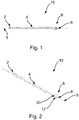
- Figure 1 shows a side view of a surgical drill bit 10 for a bone drill according to an embodiment of this invention.
- An isometric view of the drill bit 10 is shown in Figure 2 .
- the drill bit 10 has a longitudinal axis, which is indicated in Figures 1 and 2 by the dotted line labelled 5.
- the drill bit 10 also has a shaft 4.
- the shaft 4 may be elongate.
- the shaft 4 extends along the longitudinal axis 5.
- the shaft has a proximal end 2.
- the proximal end may be attachable to a bone drill.
- the proximal end 2 may form a shank, as shown in Figures 1 and 2 .
- the shank may be received in a chuck of the bone drill.
- the drill bit 10 also includes a distal end.
- the drill bit 10 has a head 6, which is located at the distal end of the shaft 4.
- the head 6 may be used to drill into the surface of a bone, typically by pressing the head 6 against the bone, in a direction along the longitudinal axis 5.
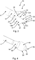
- Figure 3 shows a detailed view of the head 6 of the drill bit 10.
- the head 6 has a pointed distal tip 8.
- the pointed distal tip 8 is typically the first part of the drill bit 10 encounter the surface of a bone as the drill bit 10 drills into it.
- the pointed distal tip 8 may typically be sharp, so as to aid the entrance of the head 6 into the bone.
- the head 6 also includes a plurality of flutes 12.
- the head 6 includes four flutes 12A, 12B, 12C, 12D, although it is envisaged that a greater number or fewer number of flutes 12 may be provided.
- Each flute 12A, 12B, 12C, 12D is positioned circumferentially around the head 6.
- the flutes 12A, 12B, 12C, 12D may be evenly spaced around the circumference of the head 6.
- Each flute 12A, 12B, 12C, 12D includes a distal part 17 and a proximal part 19. As can be seen best in Figure 3 , each distal part 17 of each flute 12A, 12B, 12C, 12D extends proximally from the pointed distal tip 8. As is also shown in Figure 3 , the edges of the distal parts 17 of neighbouring pairs of the flutes 12A, 12B, 12C, 12D meet to define a plurality of cutting edges 30. The cutting edges 30 each extend proximally from the pointed distal tip 8.
- edges of a first pair of flutes 12A, 12B meet to form a first cutting edge 30, the edges of a second pair of flutes 12B, 12C meet to form a second cutting edge 30, the edges of a third pair of flutes 12C, 12D meet to form a third cutting edge 30, and the edges of a fourth pair of flutes 12D, 12A meet to form a fourth cutting edge 30.
- each flute 12A, 12B, 12C, 12D has the shape of a partial cylinder (this is discussed in more detail below in relation to Figure 4 ).
- the cylindrical shape of the surfaces of the flutes 12A, 12B, 12C, 12D gives rise to cutting edges which are concave, as is visible in Figure 3 .
- This curvature of the cutting edges 30 lead to a slightly sharper tip, owing the reduction in the angle of the cutting edge 30 relative to the longitudinal axis 5 at positions closer to the pointed distal tip 8.
- the cutting edges 30 rotate about the longitudinal axis 5, cutting into the bone as they do so.
- the flutes 12A, 12B, 12C, 12D generally act to dispense bone that has been cut away by the cutting edges 30 to the rear of the head 6, providing space for further bone to be removed.
- the head 6 also includes a bone contacting outer surface 20.
- the bone contacting outer surface 20 has a curved portion 21, which curves inwards toward the longitudinal axis 5 as it approaches the pointed distal tip 8.
- the curvature of the curved portion 21 of the bone contacting outer surface 20, as viewed in a plane containing the longitudinal axis 5 may be substantially circular.
- the proximal part 19 of each flute 12A, 12B, 12C, 12D extends proximally across this curved portion 21 of the bone contacting outer surface 20, as can be seen in Figure 3 .
- the edges 32 between the proximal parts 19 of each flute 12A, 12B, 12C, 12D may be curved (e.g. substantially elliptical).
- the inwardly curving portion 21 of the bone contacting outer surface 20, across which the proximal part 19 of each flute 12A, 12B, 12C, 12D extends can act to inhibit the lateral removal of bone by the head 6 when the drill bit 10 is moved laterally within the bone. This can allow a surgeon to use the drill bit 10 more safely and precisely, particularly in situations where he or she wants to avoid any lateral drilling/cutting of the bone by the head 6.
- the edges 32 of these parts 19 of the flutes 12A, 12B, 12C, 12D may be relatively shallow, particularly compared to the cutting edges 30. The edges 32 may therefore be unable to cut laterally into a surface of the bone as the drill bit rotates around the longitudinal axis 5.
- the curve of the bone contacting outer surface 20 may present a rounded surface at the sides of the head 6, which may inhibit the lateral removal of bone by the head 6 even when the drill bit is rotated within a plane containing the longitudinal axis 5, as with be discussed below in relation to Figure 6 .
- the proximal parts 19 of respective neighbouring pairs 12A, 12B; 12B, 12C; 12C, 12D; 12D, 12A of flutes 12 are separated from each other by a respective part 34 of the curved portion 21 of the bone contacting outer surface 20.
- Each respective part 34 of the curved portion 21 of the bone contacting outer surface 20 may be substantially V-shaped.
- the apex 36 of each substantially V-shaped part 34 may meet a proximal end of the cutting edge 30 that is defined by the edges of the distal parts 17 of the respective neighbouring pair 12A, 12B; 12B, 12C; 12C, 12D; 12D, 12A of flutes 12.
- the apex 36 is made less prominent at the lateral sides of the head 6 that it would otherwise be. This can significantly reduce the tendency of the head 6 to cut laterally into the bone as the drill bit is moved laterally, e.g. rotated within a plane containing the longitudinal axis 5.
- the bone contacting outer surface 20 also includes a proximal portion that curves inwards toward the longitudinal axis 5 with increasing distance from the pointed distal tip 8, thereby to form a neck 18 of the surgical drill bit 10.
- the neck 18 is located proximal the head 6.
- the shaft 4 of the surgical drill bit 10 may be narrower than the head 6. This has the potential benefit of providing a space to the rear of the head 6 to receive bone material that is dispensed there by the flutes.
- the proximal part 19 of each flute 12A, 12B, 12C, 12D may extend proximally across the proximal portion of the bone contacting outer surface 20 as can be seen in Figure 3 .
- the relatively narrow shaft 4 may comprise a flexible portion, allowing the drill bit 10 to travel around one or more bends inside the bone.
- Figure 4 illustrates a stage in the manufacturing of the surgical drill bit of Figures 1 to 3 , prior to the formation of the flutes 12A, 12B, 12C, 12D. It is envisaged that the same or a similar approach may be used for manufacturing other surgical rotational cutting tools such as rotary initiator devices (also known as a canal initiator tips), or straight reamers.
- rotary initiator devices also known as a canal initiator tips
- straight reamers straight reamers
- a work piece that comprises the shaft 4 of the drill bit 10, with a head portion 46.
- the head portion has a curved outer surface, the remaining parts of which (i.e. following the formation of the flutes 12A, 12B, 12C, 12D) will subsequently form the bone contacting outer surface 20 of the drill bit.
- a first part 54 of the curved outer surface may be substantially spherical. Following the formation of the flutes 12A, 12B, 12C, 12D, remaining parts of a distal part of the first part 54 of the curved outer surface may subsequently form the curved portion 21 of the bone contacting outer surface 20 that curves inwards toward the longitudinal axis 5 as it approaches the pointed distal tip 8.
- a proximal part of the first part 54, and second part 58 of the curved outer surface of the head portion 46 may together subsequently form the neck 18 of the drill bit 10.
- the head portion 46 may also include a distal conical portion 56.
- the distal conical portion 56 may extend distally from the first part 54 of the curved outer surface of the head portion 46.
- An apex 48 of the distal conical portion 56 may lay on the longitudinal axis 5. Following the formation of the flutes 12A, 12B, 12C, 12D, a remaining part of the distal conical portion 56 (perhaps including the apex 48) may subsequently form the distal pointed tip 8 of the drill bit 10.
- a tool such as a cylindrical milling cutter or ball nose cutter may be used to remove material from the head portion 46.
- a cylindrical milling cutter can give rise to flutes 12 that have surfaces that are concave and the shape of a partial cylinder.
- One cut may be made by the cylindrical milling cutter per flute 12, with each cut being circumferentially spaced around the head portion 46 at positions corresponding to the desired locations of the flutes 12.
- the cylindrical milling cutter may be oriented at an angle ⁇ with respect to the longitudinal axis 5. Consequently, a cylindrical axis of the concave cylindrical surface of each flute 12 may be oriented at an angle in the range 20° ⁇ ⁇ ⁇ 80° with respect to the longitudinal axis 5.
- a ball nose cutter may instead be used to form flutes 12 that have surfaces that are concave and the shape of a partial cylinder.
- the flutes may have a concave cross-sectional shape other than that of a partial cylinder.
- the concave surface may be a V-shaped (with the apex of the "V" pointing inwards, towards the longitudinal axis 5), or square-shaped).
- These, and other cross sectional shapes for the concave surfaces of the flute may be made using an end mill cutter.
- An axis of these flutes analogous to the cylindrical axis noted above, may be oriented at an angle in the range 20° ⁇ ⁇ ⁇ 80° with respect to the longitudinal axis 5 of the drill bit.
- each flute 12 as it extends proximally from the distal tip 8 is substantially straight, it is also envisaged that the path may be curved.
- the path may be substantially helical and/or may curve toward or away from the longitudinal axis 5.
- each flute 12 may be tilted or angled in one direction to create edges with different angles at either side of the groove formed by each flute 12. This may allow the cutting edges of each flute 12 to have a preferential rotation cutting direction compared to the opposite rotational direction. Moreover, the groove shape or tilt may change across the surface of the head 6, to further vary the edge angle.
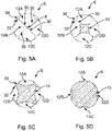
- Figures 5A to 5D show a number of views (cross sections) of the surgical drill bit 10 of the drill bit of Figures 1 to 3 , each cross section taken in a plane perpendicular to the longitudinal axis 5.
- Figure 5A shows a distal view of the head 6. From Figure 5A , it can be seen that the drill bit 10 in this example includes four flutes 12A, 12B, 12C, 12D circumferentially positioned at 90° intervals around the head 6. Consequently, the drill bit 10 includes four cutting edges 30, which are also positioned at 90° intervals around the head 6.
- the V-shaped respective parts 34 of the curved portion 21 of the bone contacting outer surface 20 are also visible in Figure 5A , showing how these part 34 curve inwards toward the longitudinal axis 5 as they approach the pointed distal tip 8, thereby to make the apexes 36 less prominent.
- Figure 5B shows a cross section through the head 6 at a position along the longitudinal axis 5 intermediate the pointed distal tip 8 and the apexes 36.
- the curved (e.g. substantially cylindrical) shape of the surfaces of the flutes 12A, 12B, 12C, 12D are visible in Figure 5B .
- Figure 5C shows a cross section through the head 6 at a position along the longitudinal axis 5 proximal the apexes 36.
- the curved (e.g. substantially cylindrical) shape of the surfaces of the flutes 12A, 12B, 12C, 12D is again visible in Figure 5C .
- Figure 5D shows a cross section through the head 6 at a position along the longitudinal axis 5 further proximal the apexes 36 with respect to the cross section of Figure 5C .
- the curved (e.g. substantially cylindrical) shape of the surfaces of the flutes 12A, 12B, 12C, 12D is once again visible in Figure 5C .
- the drill bit may include a plurality of further cutting edges 38 that are located on the shaft 4 intermediate the head 6 and the proximal end 2. These further cutting edges 38 may be used to make lateral cuts into the bone at a position located proximally with respect to the head 6.
- An example of the use of a drill bit 10 including further cutting edges 38 will now be described in relation to Figure 6 .
- the drill bit in this example is substantially as described above in relation to Figures 1 to 5 , with the addition of the plurality of further cutting edges 38. It is envisaged that the drill bit may instead of the kind to be described below in relation to Figures 7 to 11 (again, with the addition of the further cutting edges 38 on the shaft 4).
- the further cutting edges 38 may be urged laterally against the surface of the bone, as indicated schematically in Figure 6 by the arrows labelled B. Typically, this may be done after the head 8 has been used to drill into the bone along a direction parallel to the longitudinal axis 5, as indicated in Figure 6 by the arrow labelled A.
- the further cutting edges 38 may be used to widen an initial opening in the bone made by the head 6.
- the head 6 of the drill bit 10 is configured such that it does not cut laterally into a bone when the drill bit is moved laterally.
- the drill bit 10 includes the further cutting edges 38 for making lateral cuts into the bone at a position located proximally with respect to the head 6, the fact that the head 6 is so configured may allow the further cutting edges 38 with confidence, in the knowledge that this is unlikely to result in unwanted lateral cuts by the head 6.
- a surgical rotational cutting tool such as the drill bit 10 may be used to prepare a femur to receive a stem of a femoral prosthetic during a hip replacement procedure.
- a drill having a surgical drill bit 10 of the kind described above attached thereto is used to drill through a proximal cut surface of the femur to gain access to the medullary canal.
- the surgeon may position the drill bit 10 so that the head 6 is located inside the medullary canal, while the further cutting edges 38 are located at the entrance to the medullary canal.
- the further cutting edges 38 may then be used to remove bone from the medullary canal, by moving the drill bit 10 laterally as described in relation to Figure 6 . This may allow the medullary canal to be shaped to receive the stem. For instance, the further cutting edges 38 may be used to widen the entrance to the medullary canal. In one example, the further cutting edges 38 may be used to remove parts of the piriformis fossa and/or at least part of the greater trochanter that remains after the removal for the femoral neck and head. While the further cutting edges 38 are being used as described above, the head 6 may be located inside the medullary canal. As described above, the configuration of the head 6 may allow the further cutting edges 38 to be used effectively, without causing unwanted lateral removal of bone from the medullary canal by the head 6.
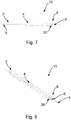
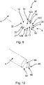
- FIG 7 shows a side view of a surgical drill bit 10 for a bone drill according to another embodiment of this invention.
- An isometric view of the drill bit 10 is shown in Figure 8 .
- Figure 9 shows a detailed view of the head 6 of the drill bit 10.
- the drill bit in this example is similar to the one described above in relation to Figures 1 to 5 , with the exception that it does not include a narrowed neck 18 of the kind included in that earlier example. Accordingly, in this example, the bone contacting outer surface 20 does not include a proximal portion that curves inwards toward the longitudinal axis 5 with increasing distance from the pointed distal tip 8 (thereby to form a neck 18 of the kind shown in the embodiment of Figure 3 ). Instead, the curved portion 21 of the bone contacting outer surface 20, which curves inwards toward the longitudinal axis 5 as it approaches the pointed distal tip 8, may terminate proximally at the base of the head, where it meets the outer surface of the shaft 4.
- the configuration of the head 6 in the embodiment of Figures 7 to 9 may be similar to that described above in relation to the embodiment of Figures 1 to 3 .
- Figure 10 illustrates a stage in the manufacturing of the surgical drill bit of Figures 7 to 9 , prior to the formation of the flutes 12A, 12B, 12C, 12D.
- rotary initiator devices also known as a canal initiator tips
- straight reamers straight reamers
- a work piece that comprises the shaft 4 of the drill bit 10, with a head portion 66.
- the head portion 66 has a curved outer surface 64, the remaining parts of which (i.e. following the formation of the flutes 12A, 12B, 12C, 12D) will subsequently form the curved portion 21 of the bone contacting outer surface 20 of the drill bit 10.
- the curved outer surface 64 may be substantially spherical (i.e. it may correspond in shape to a portion of the surface of a sphere).
- the head portion 66 may also include a distal conical portion 66.
- the distal conical portion 66 may extend distally from the curved outer surface 64.
- An apex 48 of the distal conical portion 66 may lay on the longitudinal axis 5. Following the formation of the flutes 12A, 12B, 12C, 12D, a remaining part of the distal conical portion 66 (perhaps including the apex 48) may subsequently form the distal pointed tip 8 of the drill bit 10.
- a cylindrical milling cutter or a ball nose cutter may be used substantially as described above in relation to Figure 4 to form the flutes 12, resulting in a drill bit 10 of the kind shown in Figures 7 to 9 .
- an end mill cutter may be used to form the flutes 12 instead.
- Figure 11A to 11D show a number of views (cross sections) of the surgical drill bit 10 of the drill bit of Figures 7 to 9 , each cross section taken in a plane perpendicular to the longitudinal axis 5.
- the views (cross sections) in Figures 11A to 11D are at the same positions along the longitudinal axis 5 as those in Figures 5A to 5D .
- Comparison of the views in Figures 5A to 5D with those in Figures 11A to 11D demonstrate that the head 6 of the drill bit 10 of this second embodiment is similarly configured to the head 6 in the first embodiment, at least in positions distal the proximal end of the curved portion 21.
- the surgical rotational cutting tools described herein may comprise a material such as stainless steel.
- a material such as stainless steel.
- 400 or 600 series stainless steel cold be used (e.g. 17/4 PH (600 series); 420 S29/S45; 440 B, or 440C).
- Embodiments of this invention can allow the functions of a pointed tip for initially drilling into a bone, and a lateral reamer, to be combined in a single tool. This can save manufacturing costs in the production surgical instruments for performing a surgical procedure, and can reduce the weight and size of a surgical kit incorporating the drill bit.
- a surgical kit may be provided.
- the kit may, for instance be a kit for a hip replacement procedure.
- the kit may include a plurality of surgical rotational cutting tools (e.g. drill bits) of the kind set out above. It is envisaged that some of the surgical rotational cutting tools may be of different sizes.
- the tool includes a longitudinal axis and a shaft extending along the longitudinal axis, which has a proximal end and a distal end.
- the tool also includes a head located at the distal end of the shaft.
- the head includes a pointed distal tip, a bone contacting outer surface having a portion which curves inwards toward the longitudinal axis as it approaches the tip, and a plurality of flutes. The edges of distal parts of neighbouring pairs of the flutes meet to define a plurality of cutting edges which extend proximally from the pointed distal tip. A proximal part of each flute extends proximally across the curved portion.
Description
- This invention relates to a surgical rotational cutting tool. The invention also relates to a surgical kit comprising at least one surgical rotational cutting tool.
- Hip replacement is a surgical procedure in which the hip joint is replaced by a prosthetic implant. As part of the hip replacement procedure, the femoral head is replaced with a femoral prosthetic that includes a stem, which is inserted into the medullary canal at a proximal end of the femur. The femoral prosthetic also includes a bearing surface, which is received within the acetabulum of the patient. The procedure may in some cases also involve inserting an acetabular cup into the acetabulum of the patient, for receiving the bearing surface of the femoral prosthetic.
- To prepare the femur to receive the femoral prosthetic, a cut is made at the proximal end of the femur, to remove the femoral neck and head. Thereafter tools such as drills and reamers are used to first gain access to the medullary canal and then to remove bone from the surface of the canal so as to shape it to receive the stem of the femoral prosthetic.
- More particularly, a surgical rotational cutting tool having a sharp tip may first be used to drill into the proximal cut surface of the femur to gain access to the canal. Thereafter, a tool such as an elongate reamer, which typically includes cutting edges located along its side surfaces, may then be used to remove bone from the sidewalls of the medullary canal until it is appropriately shaped to receive the stem. This step may include removing bone from the sides of the entrance to the medullary canal, to widen it. This step may also include removing a part of the greater trochanter that may remain at the proximal end of the femur following the cutting away of the femoral neck and head.
-
DE 19850980 A1 describes a reamer that has two straight, double-edged, longitudinally adjacent bits with longitudinal axis sloping towards each other. A number of blades run parallel with the longitudinal axes. The peripheral surface between the two blades is concave. The blades extend of the entire proximal part and over the adjacent part of the distal part. -
US 2006/127847 A1 describes a rotating instrument made of a ceramic material and comprising a shaft and a working member which is secured to the shaft or can detachably be secured thereto, wherein at least part of the working member is made from a ceramic material. -
US 2011/319895 A1 describes an awl that provides for creating an accurate hole in a bone, such as for implantation of a suture anchor. The awl comprises an elongated shaft having a distal tip which terminates in a sharp point adapted to penetrate bone. At least one cutting flute is provided on the shaft and has a longitudinally extending cutting edge formed on the shaft proximal to and adjacent to the sharp point whereby to allow removal of bone via the cutting flute upon rotation of the shaft about a central longitudinal axis thereof inside of the bone. -
US 2016/106441 A1 describes a bone access instrument comprising a shaft having a first shaft portion and a second shaft portion. The first shaft portion has a first diameter, a proximal end, a tapered distal end including at least three straight cutting edges being equally spaced circumferentially about the tapered distal end, and at least three flutes extending from the tapered distal end toward the proximal end in a parallel relationship to one another. The second shaft portion has a second diameter and a tapered distal end. The second diameter is less than the first diameter, and the second shaft portion extends axially from the distal end of the first shaft portion. -
US 2015/025559 A1 describes a surgical bur that includes a body and a drill point. The body includes flutes and lands. Each of the flutes includes a cutting edge, a rake face, and a clearance surface. Each of the lands is convex-shaped and disposed between a pair of the flutes. The drill point includes axial relief surfaces. Each of the axial relief surfaces has a planar area, is distinct from the lands and borders (i) a distal portion of one of the cutting edges, (ii) one of the lands, and (iii) one of the clearance surfaces. -
US 2008/132929 A1 describes a surgical bur including a shaft with a bur head. A number of flutes are formed on the bur head. Each flute has a cutting edge. The flutes are formed so that some of the flutes having cutting edges emerge from the bur head at locations relatively close to the distal end tip of the head. Still other flutes are formed so as to have cutting edges that start, extend proximally rearward, from locations that are, spaced proximal from the distal end tip. -
WO 2007/010389 A1 describes a surgical bur including a shaft with a bur head. A number of flutes are formed on the bur head. Each flute has a cutting edge. The flutes are formed so to have cutting edges extend variable lengths along the outer surface of the bur head. -
WO 2014/143597 A1 describes a retro guidewire reamer includes a cutting member, and a mechanism for moving the cutting member from a closed position to a deployed position in a single manual motion. Once a desired size of a bone tunnel is established, a surgeon uses the reamer to create a primary bone tunnel over a guidewire from the outside in. The surgeon retracts the guidewire, and activates the mechanism to deploy the cutting member within the bone joint to conform to the size of a tendon graft. The surgeon uses the deployed cutting member to create a counter bore through the bone in a retrograde manner. Once the counter bore is drilled, the surgeon activates the mechanism to close the cutting member, allowing the reamer to be withdrawn through the primary tunnel. The retro guidewire reamer can be used to provide more accurate bone tunnel placement during ligament reconstruction surgery -
WO 2004/014241 A1 describes a drill bit comprising: a shaft which has a pyramidal shaped end defining a drill tip with a plurality of edges defining the pyramidal shape; and one or more recesses for directing away debris produced whilst drilling, the or each recess having a first portion extending along the shaft and a second portion which extends along the drill tip, wherein the second portion of the or each recess extends along an edge of the drill tip. -
WO 2011/023381 A1 describes a bur which includes a shaft to which a bur head is attached. The bur head includes a plurality of flutes. Each flute at least has a rake surface and a cam surface. The rake surface extends radially outwardly from the longitudinal axis of the head. The rake surface defines a flute cutting edge. The associated cam surface curves away from the rake surface. One or more ribs extend radially outwardly from the cam surface. - Aspects of the invention are set out in the accompanying independent and dependent claims. Combinations of features from the dependent claims may be combined with features of the independent claims as appropriate and not merely as explicitly set out in the claims.
- According to an aspect of the invention, there is provided a surgical rotational cutting tool according to claim 1.
- The pointed distal tip and cutting edges, which extend proximally therefrom, can be used to cut or drill directly into bone. The inwardly curving bone contacting outer surface, across which the proximal part of each flute extends can act to inhibit the lateral removal of bone by the head when the tool is moved laterally within the bone. This can allow a surgeon to use the tool more safely and precisely, particularly in situations where he or she wants to avoid any lateral drilling/cutting of the bone by the head of the tool when it is inside the bone. In particular, because the proximal parts of each flute extend proximally across the curved portion of the bone contacting outer surface, the edges of these parts of the flutes may be relatively shallow, particularly compared to the sharper cutting edges formed by the edges of distal parts of the flutes, whereby they would are unable to cut laterally into a surface of the bone. Also, the curve of the bone contacting outer surface presents a rounded surface at the sides of the head, which may inhibit the lateral removal of bone by the head even when the lateral movement within the bone involves rotation of the head within a plane containing the longitudinal axis of the tool.
- In some examples, a plurality of further cutting edges may be located on the shaft intermediate the head and the proximal end of the shaft. These further cutting edges may be used to make lateral cuts into the bone at a position located proximally with respect to the head. These cuts can be made by moving the tool laterally within the bone, so as to urge the further cutting edges laterally against the surface of the bone. Because the head, as discussed above, has features which prevent lateral drilling/cutting by the head when it is inside the bone, the lateral removal of bone by the further cutting edges located on the shaft can be performed in a controlled manner. In particular, the surgeon need not worry about the lateral movements of the tool for urging the further cutting edges against the bone causing any unwanted removal of bone by the head. Moreover, it is envisaged that the surgeon may use the head as a non-cutting pivot point to leverage the plurality of further cutting edges located on the shaft against the surface of the bone.
- Thus, embodiments of this invention can allow the functions of a pointed tip for initially cutting or drilling into a bone, and a lateral reamer, to be combined in a single surgical rotational cutting tool. This can save manufacturing costs in the production surgical instruments for performing a surgical procedure, and can reduce the weight and size of a surgical kit incorporating the tool.
- One example of the use of a tool according to an embodiment of this invention may be during a hip replacement procedure, for preparing a femur to receive a stem of a femoral prosthetic. In particular, the pointed distal tip and cutting edges, which extend proximally from the tip, can be used to cut or drill into the proximal cut surface of a femur to gain access to the medullary canal. Thereafter, with the head of the tool located inside the medullary canal, the further cutting edges noted above may be used to remove bone from the sidewalls of the medullary canal until it is appropriately shaped to receive broaches and then the stem. This may include removing bone from the sides of the entrance to the medullary canal, to widen it, and/or removing a part of the greater trochanter that may remain at the proximal end of the femur following the cutting away of the femoral neck and head.
- In some embodiments, the angle(s) at which the edges of the distal parts of said neighbouring pairs of flutes meet to define the plurality of cutting edges are more acute than the angle(s) at the edges formed between the proximal part of each flute and the bone contacting outer surface. As noted above, the relative shallowness of the edges formed between the proximal part of each flute and the bone contacting outer surface can prevent them from cutting laterally into a surface of the bone.
- The cutting edges extending proximally from the pointed distal tip may be concave. Each flute may have a concave surface. The concave surface may be a concave cylindrical surface. This can conveniently allow the head of the tool to be formed using a cylindrical milling cutter or ball nose cutter, for forming the flutes and the pointed distal tip. Other cross sectional shapes for the flutes (e.g. V-shaped, or square-shaped) are envisaged. Where the cross sectional shape of the flutes is e.g. V-shaped, or square-shaped, an end mill cutter may be used to form them instead. An axis (e.g. a cylindrical axis) of the concave (e.g. cylindrical) surface of each flute may be oriented at an angle in the
range 20° ≤ θ ≤ 80° with respect to the longitudinal axis. This may be implemented by appropriate orientation of a cylindrical milling cutter or appropriate movement of a ball nose cutter during manufacture. The path of each flute as it extends proximally from the distal tip may be substantially straight, although it is also envisaged that the path may be curved. It is also envisaged that each flute may be tilted or angled in one direction to create edges with different angles at either side of the groove formed by each flute. This may allow the cutting edges of each flute to have a preferential rotation cutting direction compared to the opposite rotational direction. Moreover, the groove shape or tilt may change across the surface of the head, to further vary the edge angle. - Because the apex of the V-shaped part is located on the portion of the bone contacting outer surface that curves inwards toward the longitudinal axis as it approaches the tip, the point formed by the apex of the substantially V-shaped part and the proximal end of the cutting edge that is defined by the respective neighbouring pair of flutes is less sharp than it would otherwise be. This can prevent the apex from cutting laterally into a bone in contact with the bone contacting outer surface.
- The bone contacting outer surface may have a proximal portion that curves inwards toward the longitudinal axis with increasing distance from the pointed distal tip, to form a neck of the tool. The proximal part of each flute may extend proximally across the proximal portion of the bone contacting outer surface. This arrangement can allow the flutes to dispense bone that has been cut away by the cutting edges of the head to be dispensed proximally, to the rear of the head.
- At least part of the bone contacting outer surface may be substantially spherical. It is envisaged that this may be the optimal shape for inhibiting the lateral removal of bone by the head even when lateral movement of the tool within the bone involves rotation of the head within a plane containing the longitudinal axis of the tool, as discussed above.
- The flutes are equally circumferentially spaced around the head. The tool may have exactly four flutes.
- The surgical rotation cutting tool may be implemented as, or in, a number of different kinds of surgical instrument. By way of example only, it is envisaged that the surgical rotation cutting tool may be a surgical drill bit, a rotary initiator device (also known as a canal initiator tip), or a straight reamer.
- According to another aspect of the invention, there is provided a surgical kit according to claim 14. At least one of the surgical rotational cutting tools may be of a different size to at least one other of the surgical rotational cutting tools. The kit may, for instance be for a hip replacement procedure.
- A method of preparing a femur to receive a stem of a femoral prosthetic is described but not claimed, the method comprising:
- cutting away the head and neck of the femur; and
- using a surgical rotational cutting tool of the kind set out above to cut into a proximal cut surface of the femur to gain access to the medullary canal.
- As noted above, the tool may include a plurality of further cutting edges located on the shaft and proximally with respect to the head. In such examples, the method may also include positioning the tool so that the head is located inside the medullary canal while the further cutting edges are located at the entrance to the medullary canal. The method may further include moving the tool laterally to use the plurality of further cutting edges to remove bone to widen the entrance to the medullary canal.
- The method may also include moving the tool laterally to use the plurality of further cutting edges to remove at least part of the greater trochanter.
- Embodiments of the present invention will be described hereinafter, by way of example only, with reference to the accompanying drawings in which like reference signs relate to like elements and in which:
-
Figures 1 and 2 show two views of a surgical rotational cutting tool according to an embodiment of this invention; -
Figure 3 shows a detailed view of the head of the tool ofFigures 1 and 2 ; -
Figure 4 illustrates a stage in the manufacturing of the surgical rotational cutting tool ofFigures 1 to 3 , prior to the formation of the flutes of the tool; -
Figure 5A to 5D show a number of cross sections of the surgical rotational cutting tool ofFigures 1 to 3 , each cross section taken in a plane perpendicular to the longitudinal axis of the tool; -
Figure 6 illustrates the use of a surgical rotational cutting tool of the kind described inFigures 1 to 4 in accordance with an embodiment of this invention; -
Figures 7 and 8 show two views of a surgical rotational cutting tool according to another embodiment of this invention; -
Figure 9 shows a detailed view of the head of the surgical rotational cutting tool ofFigures 7 and 8 ; -
Figure 10 illustrates a stage in the manufacturing of the surgical rotational cutting tool ofFigures 7 to 9 , prior to the formation of the flutes of the tool; and -
Figures 11A to 11D show a number of cross sections of the surgical rotational cutting tool ofFigures 7 to 9 , each cross section taken in a plane perpendicular to the longitudinal axis of the tool. - Embodiments of the present invention are described in the following with reference to the accompanying drawings.
- Embodiments of this invention can provide a surgical rotation cutting tool, and a surgical kit including one or more such tools. A method is also described but not claimed, for using such a tool in the preparation of a femur to receive a stem of a femoral prosthetic. The examples shown in the figures relate particularly to a surgical rotation cutting tool that comprises a surgical drill bit. However, it is envisaged that a surgical rotation cutting tool having features of the kind described herein may be implemented as, or in, a number of different kinds of surgical instrument. For instance, it is envisaged that a surgical rotation cutting tool may be implemented as a rotary initiator device (also known as a canal initiator tip), or a straight reamer.
-
Figure 1 shows a side view of asurgical drill bit 10 for a bone drill according to an embodiment of this invention. An isometric view of thedrill bit 10 is shown inFigure 2 . - The
drill bit 10 has a longitudinal axis, which is indicated inFigures 1 and 2 by the dotted line labelled 5. Thedrill bit 10 also has ashaft 4. Theshaft 4 may be elongate. Theshaft 4 extends along thelongitudinal axis 5. The shaft has aproximal end 2. The proximal end may be attachable to a bone drill. Theproximal end 2 may form a shank, as shown inFigures 1 and 2 . To attach thedrill bit 10 to the bone drill, the shank may be received in a chuck of the bone drill. Thedrill bit 10 also includes a distal end. As shown in the Figures, thedrill bit 10 has ahead 6, which is located at the distal end of theshaft 4. Thehead 6 may be used to drill into the surface of a bone, typically by pressing thehead 6 against the bone, in a direction along thelongitudinal axis 5. -
Figure 3 shows a detailed view of thehead 6 of thedrill bit 10. - The
head 6 has a pointeddistal tip 8. The pointeddistal tip 8 is typically the first part of thedrill bit 10 encounter the surface of a bone as thedrill bit 10 drills into it. The pointeddistal tip 8 may typically be sharp, so as to aid the entrance of thehead 6 into the bone. - The
head 6 also includes a plurality offlutes 12. In the present example, thehead 6 includes fourflutes flutes 12 may be provided. Eachflute head 6. For instance, theflutes head 6. - Each
flute distal part 17 and aproximal part 19. As can be seen best inFigure 3 , eachdistal part 17 of eachflute distal tip 8. As is also shown inFigure 3 , the edges of thedistal parts 17 of neighbouring pairs of theflutes distal tip 8. For instance, in the present example, the edges of a first pair offlutes first cutting edge 30, the edges of a second pair offlutes second cutting edge 30, the edges of a third pair offlutes third cutting edge 30, and the edges of a fourth pair offlutes fourth cutting edge 30. - In the present example, the surface of each
flute Figure 4 ). The cylindrical shape of the surfaces of theflutes Figure 3 . This curvature of the cutting edges 30 lead to a slightly sharper tip, owing the reduction in the angle of thecutting edge 30 relative to thelongitudinal axis 5 at positions closer to the pointeddistal tip 8. - In use, the cutting edges 30 rotate about the
longitudinal axis 5, cutting into the bone as they do so. Theflutes head 6, providing space for further bone to be removed. - The
head 6 also includes a bone contactingouter surface 20. The bone contactingouter surface 20 has acurved portion 21, which curves inwards toward thelongitudinal axis 5 as it approaches the pointeddistal tip 8. The curvature of thecurved portion 21 of the bone contactingouter surface 20, as viewed in a plane containing thelongitudinal axis 5 may be substantially circular. Theproximal part 19 of eachflute curved portion 21 of the bone contactingouter surface 20, as can be seen inFigure 3 . Theedges 32 between theproximal parts 19 of eachflute - The inwardly curving
portion 21 of the bone contactingouter surface 20, across which theproximal part 19 of eachflute head 6 when thedrill bit 10 is moved laterally within the bone. This can allow a surgeon to use thedrill bit 10 more safely and precisely, particularly in situations where he or she wants to avoid any lateral drilling/cutting of the bone by thehead 6. - In particular, because the
proximal parts 19 of eachflute curved portion 21 of the bone contactingouter surface 20, theedges 32 of theseparts 19 of theflutes edges 32 may therefore be unable to cut laterally into a surface of the bone as the drill bit rotates around thelongitudinal axis 5. Also, the curve of the bone contactingouter surface 20 may present a rounded surface at the sides of thehead 6, which may inhibit the lateral removal of bone by thehead 6 even when the drill bit is rotated within a plane containing thelongitudinal axis 5, as with be discussed below in relation toFigure 6 . - As can be seen in
Figure 3 , in the present example, theproximal parts 19 of respective neighbouringpairs flutes 12 are separated from each other by arespective part 34 of thecurved portion 21 of the bone contactingouter surface 20. Eachrespective part 34 of thecurved portion 21 of the bone contactingouter surface 20 may be substantially V-shaped. The apex 36 of each substantially V-shapedpart 34 may meet a proximal end of thecutting edge 30 that is defined by the edges of thedistal parts 17 of the respectiveneighbouring pair flutes 12. Note that because thecurved portion 21 of the bone contactingouter surface 20 curves inwards toward thelongitudinal axis 5 as it approaches the pointeddistal tip 8, the apex 36 is made less prominent at the lateral sides of thehead 6 that it would otherwise be. This can significantly reduce the tendency of thehead 6 to cut laterally into the bone as the drill bit is moved laterally, e.g. rotated within a plane containing thelongitudinal axis 5. - In the present example, the bone contacting
outer surface 20 also includes a proximal portion that curves inwards toward thelongitudinal axis 5 with increasing distance from the pointeddistal tip 8, thereby to form aneck 18 of thesurgical drill bit 10. Theneck 18 is located proximal thehead 6. In such examples, theshaft 4 of thesurgical drill bit 10 may be narrower than thehead 6. This has the potential benefit of providing a space to the rear of thehead 6 to receive bone material that is dispensed there by the flutes. In this respect, note that it is envisaged that theproximal part 19 of eachflute outer surface 20 as can be seen inFigure 3 . It is also envisaged that the relativelynarrow shaft 4 may comprise a flexible portion, allowing thedrill bit 10 to travel around one or more bends inside the bone. -
Figure 4 illustrates a stage in the manufacturing of the surgical drill bit ofFigures 1 to 3 , prior to the formation of theflutes - To form the
drill bit 10, there may first be provided a work piece that comprises theshaft 4 of thedrill bit 10, with ahead portion 46. In the present example, the head portion has a curved outer surface, the remaining parts of which (i.e. following the formation of theflutes outer surface 20 of the drill bit. Afirst part 54 of the curved outer surface may be substantially spherical. Following the formation of theflutes first part 54 of the curved outer surface may subsequently form thecurved portion 21 of the bone contactingouter surface 20 that curves inwards toward thelongitudinal axis 5 as it approaches the pointeddistal tip 8. A proximal part of thefirst part 54, andsecond part 58 of the curved outer surface of thehead portion 46 may together subsequently form theneck 18 of thedrill bit 10. - The
head portion 46 may also include a distalconical portion 56. The distalconical portion 56 may extend distally from thefirst part 54 of the curved outer surface of thehead portion 46. An apex 48 of the distalconical portion 56 may lay on thelongitudinal axis 5. Following the formation of theflutes pointed tip 8 of thedrill bit 10. - To form the
flutes 12 of thedrill bit 10, a tool such as a cylindrical milling cutter or ball nose cutter may be used to remove material from thehead portion 46. - For instance, the use of a cylindrical milling cutter can give rise to
flutes 12 that have surfaces that are concave and the shape of a partial cylinder. One cut may be made by the cylindrical milling cutter perflute 12, with each cut being circumferentially spaced around thehead portion 46 at positions corresponding to the desired locations of theflutes 12. The cylindrical milling cutter may be oriented at an angle θ with respect to thelongitudinal axis 5. Consequently, a cylindrical axis of the concave cylindrical surface of eachflute 12 may be oriented at an angle in therange 20° ≤ θ ≤ 80° with respect to thelongitudinal axis 5. It is envisaged that a ball nose cutter may instead be used to formflutes 12 that have surfaces that are concave and the shape of a partial cylinder. - As noted previously, it is envisaged that the flutes may have a concave cross-sectional shape other than that of a partial cylinder. For instance, the concave surface may be a V-shaped (with the apex of the "V" pointing inwards, towards the longitudinal axis 5), or square-shaped). These, and other cross sectional shapes for the concave surfaces of the flute may be made using an end mill cutter. An axis of these flutes, analogous to the cylindrical axis noted above, may be oriented at an angle in the
range 20° ≤ θ ≤ 80° with respect to thelongitudinal axis 5 of the drill bit. - Although in the examples shown in the Figures the path of each
flute 12 as it extends proximally from thedistal tip 8 is substantially straight, it is also envisaged that the path may be curved. For instance, the path may be substantially helical and/or may curve toward or away from thelongitudinal axis 5. - It is also envisaged that each
flute 12 may be tilted or angled in one direction to create edges with different angles at either side of the groove formed by eachflute 12. This may allow the cutting edges of eachflute 12 to have a preferential rotation cutting direction compared to the opposite rotational direction. Moreover, the groove shape or tilt may change across the surface of thehead 6, to further vary the edge angle. -
Figures 5A to 5D show a number of views (cross sections) of thesurgical drill bit 10 of the drill bit ofFigures 1 to 3 , each cross section taken in a plane perpendicular to thelongitudinal axis 5. -
Figure 5A shows a distal view of thehead 6. FromFigure 5A , it can be seen that thedrill bit 10 in this example includes fourflutes head 6. Consequently, thedrill bit 10 includes fourcutting edges 30, which are also positioned at 90° intervals around thehead 6. The V-shapedrespective parts 34 of thecurved portion 21 of the bone contactingouter surface 20 are also visible inFigure 5A , showing how thesepart 34 curve inwards toward thelongitudinal axis 5 as they approach the pointeddistal tip 8, thereby to make theapexes 36 less prominent. -
Figure 5B shows a cross section through thehead 6 at a position along thelongitudinal axis 5 intermediate the pointeddistal tip 8 and theapexes 36. The curved (e.g. substantially cylindrical) shape of the surfaces of theflutes Figure 5B . -
Figure 5C shows a cross section through thehead 6 at a position along thelongitudinal axis 5 proximal theapexes 36. The curved (e.g. substantially cylindrical) shape of the surfaces of theflutes Figure 5C . -
Figure 5D shows a cross section through thehead 6 at a position along thelongitudinal axis 5 further proximal theapexes 36 with respect to the cross section ofFigure 5C . The curved (e.g. substantially cylindrical) shape of the surfaces of theflutes Figure 5C . - In some examples, the drill bit may include a plurality of further cutting
edges 38 that are located on theshaft 4 intermediate thehead 6 and theproximal end 2. These further cuttingedges 38 may be used to make lateral cuts into the bone at a position located proximally with respect to thehead 6. An example of the use of adrill bit 10 including further cuttingedges 38 will now be described in relation toFigure 6 . - As can be seen in
Figure 6 , the drill bit in this example is substantially as described above in relation toFigures 1 to 5 , with the addition of the plurality of further cutting edges 38. It is envisaged that the drill bit may instead of the kind to be described below in relation toFigures 7 to 11 (again, with the addition of thefurther cutting edges 38 on the shaft 4). - To use the
further cutting edges 38, they may be urged laterally against the surface of the bone, as indicated schematically inFigure 6 by the arrows labelled B. Typically, this may be done after thehead 8 has been used to drill into the bone along a direction parallel to thelongitudinal axis 5, as indicated inFigure 6 by the arrow labelled A. In some examples, thefurther cutting edges 38 may be used to widen an initial opening in the bone made by thehead 6. When performing the lateral movements B for urging thefurther cutting edges 38 laterally against the surface of the bone, it will be appreciated that thehead 6 may be located inside the bone. - As described above, the
head 6 of thedrill bit 10 is configured such that it does not cut laterally into a bone when the drill bit is moved laterally. Where thedrill bit 10 includes thefurther cutting edges 38 for making lateral cuts into the bone at a position located proximally with respect to thehead 6, the fact that thehead 6 is so configured may allow thefurther cutting edges 38 with confidence, in the knowledge that this is unlikely to result in unwanted lateral cuts by thehead 6. - In one particular example, a surgical rotational cutting tool such as the
drill bit 10 may be used to prepare a femur to receive a stem of a femoral prosthetic during a hip replacement procedure. In this example, after cutting away the head and neck of the femur, a drill having asurgical drill bit 10 of the kind described above attached thereto is used to drill through a proximal cut surface of the femur to gain access to the medullary canal. Thereafter, the surgeon may position thedrill bit 10 so that thehead 6 is located inside the medullary canal, while thefurther cutting edges 38 are located at the entrance to the medullary canal. Thefurther cutting edges 38 may then be used to remove bone from the medullary canal, by moving thedrill bit 10 laterally as described in relation toFigure 6 . This may allow the medullary canal to be shaped to receive the stem. For instance, thefurther cutting edges 38 may be used to widen the entrance to the medullary canal. In one example, thefurther cutting edges 38 may be used to remove parts of the piriformis fossa and/or at least part of the greater trochanter that remains after the removal for the femoral neck and head. While thefurther cutting edges 38 are being used as described above, thehead 6 may be located inside the medullary canal. As described above, the configuration of thehead 6 may allow thefurther cutting edges 38 to be used effectively, without causing unwanted lateral removal of bone from the medullary canal by thehead 6. -
Figure 7 shows a side view of asurgical drill bit 10 for a bone drill according to another embodiment of this invention. An isometric view of thedrill bit 10 is shown inFigure 8 .Figure 9 shows a detailed view of thehead 6 of thedrill bit 10. - The drill bit in this example is similar to the one described above in relation to
Figures 1 to 5 , with the exception that it does not include a narrowedneck 18 of the kind included in that earlier example. Accordingly, in this example, the bone contactingouter surface 20 does not include a proximal portion that curves inwards toward thelongitudinal axis 5 with increasing distance from the pointed distal tip 8 (thereby to form aneck 18 of the kind shown in the embodiment ofFigure 3 ). Instead, thecurved portion 21 of the bone contactingouter surface 20, which curves inwards toward thelongitudinal axis 5 as it approaches the pointeddistal tip 8, may terminate proximally at the base of the head, where it meets the outer surface of theshaft 4. - In other respects, the configuration of the
head 6 in the embodiment ofFigures 7 to 9 may be similar to that described above in relation to the embodiment ofFigures 1 to 3 . -
Figure 10 illustrates a stage in the manufacturing of the surgical drill bit ofFigures 7 to 9 , prior to the formation of theflutes - To form the
drill bit 10, there may first be provided a work piece that comprises theshaft 4 of thedrill bit 10, with ahead portion 66. In the present example, thehead portion 66 has a curvedouter surface 64, the remaining parts of which (i.e. following the formation of theflutes curved portion 21 of the bone contactingouter surface 20 of thedrill bit 10. The curvedouter surface 64 may be substantially spherical (i.e. it may correspond in shape to a portion of the surface of a sphere). - The
head portion 66 may also include a distalconical portion 66. The distalconical portion 66 may extend distally from the curvedouter surface 64. An apex 48 of the distalconical portion 66 may lay on thelongitudinal axis 5. Following the formation of theflutes pointed tip 8 of thedrill bit 10. - Starting with the work piece shown in
Figure 10 , a cylindrical milling cutter or a ball nose cutter may be used substantially as described above in relation toFigure 4 to form theflutes 12, resulting in adrill bit 10 of the kind shown inFigures 7 to 9 . Again, in embodiments in which theflutes 12 are V-shaped or square, then an end mill cutter may be used to form theflutes 12 instead. -
Figure 11A to 11D show a number of views (cross sections) of thesurgical drill bit 10 of the drill bit ofFigures 7 to 9 , each cross section taken in a plane perpendicular to thelongitudinal axis 5. The views (cross sections) inFigures 11A to 11D are at the same positions along thelongitudinal axis 5 as those inFigures 5A to 5D . Comparison of the views inFigures 5A to 5D with those inFigures 11A to 11D demonstrate that thehead 6 of thedrill bit 10 of this second embodiment is similarly configured to thehead 6 in the first embodiment, at least in positions distal the proximal end of thecurved portion 21. - The surgical rotational cutting tools described herein may comprise a material such as stainless steel. By way of example, 400 or 600 series stainless steel cold be used (e.g. 17/4 PH (600 series); 420 S29/S45; 440 B, or 440C).
- Embodiments of this invention can allow the functions of a pointed tip for initially drilling into a bone, and a lateral reamer, to be combined in a single tool. This can save manufacturing costs in the production surgical instruments for performing a surgical procedure, and can reduce the weight and size of a surgical kit incorporating the drill bit.
- According to embodiments of this invention, a surgical kit may be provided. The kit may, for instance be a kit for a hip replacement procedure. The kit may include a plurality of surgical rotational cutting tools (e.g. drill bits) of the kind set out above. It is envisaged that some of the surgical rotational cutting tools may be of different sizes.
- Accordingly, there has been described a surgical rotational cutting tool, a surgical kit and a method of preparing a femur to receive a stem of a femoral prosthetic. The tool includes a longitudinal axis and a shaft extending along the longitudinal axis, which has a proximal end and a distal end. The tool also includes a head located at the distal end of the shaft. The head includes a pointed distal tip, a bone contacting outer surface having a portion which curves inwards toward the longitudinal axis as it approaches the tip, and a plurality of flutes. The edges of distal parts of neighbouring pairs of the flutes meet to define a plurality of cutting edges which extend proximally from the pointed distal tip. A proximal part of each flute extends proximally across the curved portion.
- Although particular embodiments of the invention have been described, it will be appreciated that many modifications/additions and/or substitutions may be made within the scope of the claimed invention, which is defined by the appended claims.
Claims (14)
- A surgical rotational cutting tool (10) comprising:a longitudinal axis (5);a shaft (4) extending along the longitudinal axis and having a proximal end (2) and a distal end; anda head (6) located at the distal end of the shaft, the head comprising:a pointed distal tip (8);a bone contacting outer surface (20) having a curved portion (21) which curves inwards toward the longitudinal axis as it approaches the tip; anda plurality of flutes (12A, 12B, 12C, 12D) positioned circumferentially around the head, wherein each flute includes a proximal part (19) and a distal part (17), wherein each distal part extends proximally from the pointed distal tip, wherein the edges of the distal parts of neighbouring pairs of said circumferentially positioned flutes meet to define a plurality of cutting edges (30) which extend proximally from the pointed distal tip, wherein the proximal part of each flute extends proximally across the curved portion of the bone contacting outer surface, wherein the proximal parts of respective neighbouring pairs of flutes are separated from each other by a respective part of the curved portion of the bone contacting outer surface, wherein each respective part of the curved portion of the bone contacting outer surface is substantially V-shaped, and wherein the apex (36) of each substantially V-shaped part meets a proximal end of the cutting edge that is defined by the said respective neighbouring pair of flutes.
- The surgical rotational cutting tool of any preceding claim comprising a plurality of further cutting edges (38) located on the shaft intermediate the head and the proximal end of the shaft.
- The surgical rotational cutting tool of claim 1 or claim 2, wherein the angle(s) at which the edges of the distal parts of said neighbouring pairs of flutes meet to define the plurality of cutting edges are more acute than the angle(s) at the edges formed between the proximal part of each flute and the bone contacting outer surface.
- The surgical rotational cutting tool of any preceding claim, wherein the cutting edges extending proximally from the pointed distal tip are concave.
- The surgical rotational cutting tool of any preceding claim, wherein each flute comprises a concave surface.
- The surgical rotational cutting tool of claim 5, wherein an axis of the concave surface of each flute is oriented at an angle in the range 20° ≤ θ ≤ 80° with respect to the longitudinal axis.
- The surgical rotational cutting tool of claim 5 or claim 6, wherein the concave surface of each flute is a concave cylindrical surface.
- The surgical rotational cutting tool of any preceding claim, wherein the bone contacting outer surface has a proximal portion that curves inwards toward the longitudinal axis with increasing distance from the pointed distal tip, to form a neck of the surgical rotational cutting tool.
- The surgical rotational cutting tool of claim 8, wherein the proximal part of each flute extends proximally across the proximal portion of the bone contacting outer surface.
- The surgical rotational cutting tool of any preceding claim, wherein at least part of the bone contacting outer surface is substantially spherical.
- The surgical rotational cutting tool of any preceding claim wherein the flutes are equally circumferentially spaced around the head.
- The surgical rotational cutting tool of any preceding claim comprising four said flutes.
- The surgical rotational cutting tool of any preceding claim, wherein the tool is a surgical drill bit, rotary initiator device, or a straight reamer.
- A surgical kit comprising a plurality of surgical rotational cutting tools (10) according to any preceding claim, wherein at least one of said surgical rotational cutting tools is of a different size to at least one other of said surgical rotational cutting tools.
Applications Claiming Priority (3)
| Application Number | Priority Date | Filing Date | Title |
|---|---|---|---|
| GBGB1702404.3A GB201702404D0 (en) | 2017-02-14 | 2017-02-14 | A surgical rotational cutting tool and method |
| PCT/EP2018/051682 WO2018149602A1 (en) | 2017-02-14 | 2018-01-24 | A surgical rotational cutting tool |
| EP18702449.2A EP3582700B1 (en) | 2017-02-14 | 2018-01-24 | A surgical rotational cutting tool |
Related Parent Applications (1)
| Application Number | Title | Priority Date | Filing Date |
|---|---|---|---|
| EP18702449.2A Division EP3582700B1 (en) | 2017-02-14 | 2018-01-24 | A surgical rotational cutting tool |
Publications (2)
| Publication Number | Publication Date |
|---|---|
| EP3912570A1 EP3912570A1 (en) | 2021-11-24 |
| EP3912570B1 true EP3912570B1 (en) | 2022-10-05 |
Family
ID=58462142
Family Applications (2)
| Application Number | Title | Priority Date | Filing Date |
|---|---|---|---|
| EP18702449.2A Active EP3582700B1 (en) | 2017-02-14 | 2018-01-24 | A surgical rotational cutting tool |
| EP21177604.2A Active EP3912570B1 (en) | 2017-02-14 | 2018-01-24 | A surgical rotational cutting tool |
Family Applications Before (1)
| Application Number | Title | Priority Date | Filing Date |
|---|---|---|---|
| EP18702449.2A Active EP3582700B1 (en) | 2017-02-14 | 2018-01-24 | A surgical rotational cutting tool |
Country Status (7)
| Country | Link |
|---|---|
| US (1) | US11160566B2 (en) |
| EP (2) | EP3582700B1 (en) |
| JP (2) | JP6992078B2 (en) |
| CN (2) | CN110300555B (en) |
| AU (2) | AU2018220755B2 (en) |
| GB (1) | GB201702404D0 (en) |
| WO (1) | WO2018149602A1 (en) |
Families Citing this family (3)
| Publication number | Priority date | Publication date | Assignee | Title |
|---|---|---|---|---|
| GB201702404D0 (en) * | 2017-02-14 | 2017-03-29 | Depuy Ireland Ultd Co | A surgical rotational cutting tool and method |
| CN110840516A (en) * | 2019-12-02 | 2020-02-28 | 北京市春立正达医疗器械股份有限公司 | Hole opening tool bit and hole opening device using same |
| USD956222S1 (en) | 2020-08-21 | 2022-06-28 | Stryker European Operations Limited | Surgical bur assembly |
Family Cites Families (30)
| Publication number | Priority date | Publication date | Assignee | Title |
|---|---|---|---|---|
| CA1060744A (en) * | 1975-09-05 | 1979-08-21 | Vernon H. Troutner | Wire inserter and sterile wire pack |
| DE19850980C2 (en) | 1998-11-05 | 2000-11-16 | Aesculap Ag & Co Kg | Reamer to prepare a bone cavity |
| AU2000226357A1 (en) * | 1999-02-01 | 2000-08-18 | Garland U. Edwards | Surgical reamer cutter |
| NZ537852A (en) | 2002-08-08 | 2008-10-31 | Surgibit Ip Holdings Pty Ltd | A drill bit and method for producing a drill bit |
| DE10243104A1 (en) | 2002-09-17 | 2004-03-25 | Gebr. Brasseler Gmbh & Co. Kg | Rotating ceramic tool with a ceramic cutting head bonded to a ceramic or metal support shaft |
| US20080132929A1 (en) * | 2005-07-19 | 2008-06-05 | O'sullivan Denis F | Surgical bur with anti-chatter flute geometry |
| JP2009501597A (en) | 2005-07-19 | 2009-01-22 | ストライカー・アイルランド・リミテッド | Surgical bar with anti-chatter ridge shape |
| JP5233392B2 (en) | 2008-04-30 | 2013-07-10 | 東洋インキScホールディングス株式会社 | Polyurethane polyurea adhesive, curable electromagnetic wave shielding adhesive film using the same, and method for producing the same |
| US8029509B2 (en) * | 2006-03-07 | 2011-10-04 | Orthohelix Surgical Designs, Inc. | Countersink for use in orthopedic surgery |
| JP2010510042A (en) * | 2006-11-22 | 2010-04-02 | ソノマ・オーソペディック・プロダクツ・インコーポレイテッド | Tools for use in the placement of bone repair devices |
| US8460298B2 (en) | 2007-08-15 | 2013-06-11 | Stryker Ireland Ltd. | Surgical bur with unequally spaced flutes, flutes with different rake angles and flutes with alternating reliefs |
| CN201422900Y (en) * | 2009-06-29 | 2010-03-17 | 中国人民解放军第一零五医院 | Acetabular fossa trigone drill bit for artificial hip replacement |
| BR112012004183B1 (en) | 2009-08-26 | 2019-12-03 | Stryker European Holdings I Llc | surgical drill to remove or remove tissue from a surgical site |
| US20110238099A1 (en) | 2010-03-24 | 2011-09-29 | Smith & Nephew, Inc. | Arthroscopic Resection Devices |
| US20110319895A1 (en) | 2010-06-25 | 2011-12-29 | Depuy Mitek, Inc. | Fluted bone awl and method of use |
| EP2683327B1 (en) * | 2011-03-11 | 2017-11-29 | Smith & Nephew, Inc. | Trephine |
| US9326778B2 (en) * | 2011-03-23 | 2016-05-03 | Huwais IP Holding LLC | Autografting osteotome |
| KR102044794B1 (en) * | 2011-07-06 | 2019-11-14 | 노벨 바이오케어 서비시스 아게 | Screw and driver tool |
| US9232952B2 (en) * | 2012-04-16 | 2016-01-12 | Medtronic Ps Medical, Inc. | Surgical bur with non-paired flutes |
| US9226756B2 (en) | 2012-05-14 | 2016-01-05 | DePuy Synthes Products, Inc. | Bone access instrument |
| JP2015527153A (en) * | 2012-09-07 | 2015-09-17 | ストライカー・アイルランド・リミテッド | Surgical bar with a blade groove having a rake face that varies both in helix angle and rake angle |
| GB2509739A (en) | 2013-01-11 | 2014-07-16 | Nobel Biocare Services Ag | Dental drill bit with spherical head and helical fluting |
| KR20150126615A (en) | 2013-03-12 | 2015-11-12 | 스미스 앤드 네퓨, 인크. | Retro guidewire reamer |
| US9883873B2 (en) * | 2013-07-17 | 2018-02-06 | Medtronic Ps Medical, Inc. | Surgical burs with geometries having non-drifting and soft tissue protective characteristics |
| TW201536239A (en) * | 2013-11-06 | 2015-10-01 | Depuy Synthes Products Llc | Clavicle reamer |
| CN103690220A (en) * | 2013-12-18 | 2014-04-02 | 无锡雨田精密工具有限公司 | Medical reamer |
| US10335166B2 (en) * | 2014-04-16 | 2019-07-02 | Medtronics Ps Medical, Inc. | Surgical burs with decoupled rake surfaces and corresponding axial and radial rake angles |
| JP6341506B2 (en) * | 2014-06-24 | 2018-06-13 | 長田電機工業株式会社 | Cutting tools and bone surgery instruments |
| US9955981B2 (en) * | 2015-03-31 | 2018-05-01 | Medtronic Xomed, Inc | Surgical burs with localized auxiliary flutes |
| GB201702404D0 (en) * | 2017-02-14 | 2017-03-29 | Depuy Ireland Ultd Co | A surgical rotational cutting tool and method |
-
2017
- 2017-02-14 GB GBGB1702404.3A patent/GB201702404D0/en not_active Ceased
-
2018
- 2018-01-24 JP JP2019543862A patent/JP6992078B2/en active Active
- 2018-01-24 AU AU2018220755A patent/AU2018220755B2/en active Active
- 2018-01-24 WO PCT/EP2018/051682 patent/WO2018149602A1/en unknown
- 2018-01-24 CN CN201880011902.1A patent/CN110300555B/en active Active
- 2018-01-24 US US16/485,494 patent/US11160566B2/en active Active
- 2018-01-24 CN CN202210181757.XA patent/CN114601524A/en active Pending
- 2018-01-24 EP EP18702449.2A patent/EP3582700B1/en active Active
- 2018-01-24 EP EP21177604.2A patent/EP3912570B1/en active Active
-
2021
- 2021-12-08 JP JP2021199197A patent/JP7210688B2/en active Active
- 2021-12-15 AU AU2021286311A patent/AU2021286311B2/en active Active
Also Published As
| Publication number | Publication date |
|---|---|
| AU2021286311B2 (en) | 2023-03-30 |
| CN114601524A (en) | 2022-06-10 |
| EP3582700B1 (en) | 2021-06-09 |
| CN110300555A (en) | 2019-10-01 |
| JP2020506018A (en) | 2020-02-27 |
| US11160566B2 (en) | 2021-11-02 |
| AU2021286311A1 (en) | 2022-01-20 |
| WO2018149602A1 (en) | 2018-08-23 |
| GB201702404D0 (en) | 2017-03-29 |
| EP3582700A1 (en) | 2019-12-25 |
| AU2018220755B2 (en) | 2022-09-08 |
| JP2022022369A (en) | 2022-02-03 |
| JP7210688B2 (en) | 2023-01-23 |
| US20200046378A1 (en) | 2020-02-13 |
| EP3912570A1 (en) | 2021-11-24 |
| AU2018220755A1 (en) | 2019-08-08 |
| CN110300555B (en) | 2022-07-29 |
| JP6992078B2 (en) | 2022-01-13 |
Similar Documents
| Publication | Publication Date | Title |
|---|---|---|
| AU2021286311B2 (en) | A surgical rotational cutting tool | |
| JP4436252B2 (en) | Reamer assembly | |
| US8523866B2 (en) | Modular tapered hollow reamer for medical applications | |
| EP1528892B1 (en) | A drill bit and method for producing a drill bit | |
| EP1535579A2 (en) | Expandable reamer | |
| US9107677B2 (en) | Disposable surgical hemispherical cutter for convex and concave surfaces | |
| US7918856B2 (en) | Guided reamer system for reshaping bone | |
| US20160192945A1 (en) | Precessional-motion bone and dental drilling tools and bone harvesting apparatus | |
| EP1980216A2 (en) | Articular cartilage repair implant delivery device | |
| CN105142552B (en) | General length screw designs and cutting device | |
| EP3205294B1 (en) | Cutting heads for intramedullary reamers | |
| US8403931B2 (en) | Modular tapered hollow reamer for medical applications | |
| US20220409384A1 (en) | Annular cutting tools for resecting a bone graft and related methods | |
| US20230000499A1 (en) | A unit for the reaming of the surface of joint cartilage and of periarticular bone of an acetabulum and femoral head | |
| US10441297B2 (en) | Sounder for sizing bone implant | |
| WO2013179002A1 (en) | A trial instrument for use in orthopaedic surgery |
Legal Events
| Date | Code | Title | Description |
|---|---|---|---|
| PUAI | Public reference made under article 153(3) epc to a published international application that has entered the european phase |
Free format text: ORIGINAL CODE: 0009012 |
|
| STAA | Information on the status of an ep patent application or granted ep patent |
Free format text: STATUS: THE APPLICATION HAS BEEN PUBLISHED |
|
| AC | Divisional application: reference to earlier application |
Ref document number: 3582700 Country of ref document: EP Kind code of ref document: P |
|
| AK | Designated contracting states |
Kind code of ref document: A1 Designated state(s): AL AT BE BG CH CY CZ DE DK EE ES FI FR GB GR HR HU IE IS IT LI LT LU LV MC MK MT NL NO PL PT RO RS SE SI SK SM TR |
|
| B565 | Issuance of search results under rule 164(2) epc |
Effective date: 20210929 |
|
| STAA | Information on the status of an ep patent application or granted ep patent |
Free format text: STATUS: REQUEST FOR EXAMINATION WAS MADE |
|
| 17P | Request for examination filed |
Effective date: 20220124 |
|
| RBV | Designated contracting states (corrected) |
Designated state(s): AL AT BE BG CH CY CZ DE DK EE ES FI FR GB GR HR HU IE IS IT LI LT LU LV MC MK MT NL NO PL PT RO RS SE SI SK SM TR |
|
| GRAP | Despatch of communication of intention to grant a patent |
Free format text: ORIGINAL CODE: EPIDOSNIGR1 |
|
| STAA | Information on the status of an ep patent application or granted ep patent |
Free format text: STATUS: GRANT OF PATENT IS INTENDED |
|
| INTG | Intention to grant announced |
Effective date: 20220603 |
|
| GRAS | Grant fee paid |
Free format text: ORIGINAL CODE: EPIDOSNIGR3 |
|
| GRAA | (expected) grant |
Free format text: ORIGINAL CODE: 0009210 |
|
| STAA | Information on the status of an ep patent application or granted ep patent |
Free format text: STATUS: THE PATENT HAS BEEN GRANTED |
|
| AC | Divisional application: reference to earlier application |
Ref document number: 3582700 Country of ref document: EP Kind code of ref document: P |
|
| AK | Designated contracting states |
Kind code of ref document: B1 Designated state(s): AL AT BE BG CH CY CZ DE DK EE ES FI FR GB GR HR HU IE IS IT LI LT LU LV MC MK MT NL NO PL PT RO RS SE SI SK SM TR |
|
| REG | Reference to a national code |
Ref country code: GB Ref legal event code: FG4D |
|
| REG | Reference to a national code |
Ref country code: CH Ref legal event code: EP |
|
| REG | Reference to a national code |
Ref country code: AT Ref legal event code: REF Ref document number: 1522252 Country of ref document: AT Kind code of ref document: T Effective date: 20221015 |
|
| REG | Reference to a national code |
Ref country code: DE Ref legal event code: R096 Ref document number: 602018041589 Country of ref document: DE |
|
| REG | Reference to a national code |
Ref country code: IE Ref legal event code: FG4D |
|
| REG | Reference to a national code |
Ref country code: LT Ref legal event code: MG9D |
|
| REG | Reference to a national code |
Ref country code: NL Ref legal event code: MP Effective date: 20221005 |
|
| REG | Reference to a national code |
Ref country code: AT Ref legal event code: MK05 Ref document number: 1522252 Country of ref document: AT Kind code of ref document: T Effective date: 20221005 |
|
| PG25 | Lapsed in a contracting state [announced via postgrant information from national office to epo] |
Ref country code: NL Free format text: LAPSE BECAUSE OF FAILURE TO SUBMIT A TRANSLATION OF THE DESCRIPTION OR TO PAY THE FEE WITHIN THE PRESCRIBED TIME-LIMIT Effective date: 20221005 |
|
| PG25 | Lapsed in a contracting state [announced via postgrant information from national office to epo] |
Ref country code: SE Free format text: LAPSE BECAUSE OF FAILURE TO SUBMIT A TRANSLATION OF THE DESCRIPTION OR TO PAY THE FEE WITHIN THE PRESCRIBED TIME-LIMIT Effective date: 20221005 Ref country code: PT Free format text: LAPSE BECAUSE OF FAILURE TO SUBMIT A TRANSLATION OF THE DESCRIPTION OR TO PAY THE FEE WITHIN THE PRESCRIBED TIME-LIMIT Effective date: 20230206 Ref country code: NO Free format text: LAPSE BECAUSE OF FAILURE TO SUBMIT A TRANSLATION OF THE DESCRIPTION OR TO PAY THE FEE WITHIN THE PRESCRIBED TIME-LIMIT Effective date: 20230105 Ref country code: LT Free format text: LAPSE BECAUSE OF FAILURE TO SUBMIT A TRANSLATION OF THE DESCRIPTION OR TO PAY THE FEE WITHIN THE PRESCRIBED TIME-LIMIT Effective date: 20221005 Ref country code: FI Free format text: LAPSE BECAUSE OF FAILURE TO SUBMIT A TRANSLATION OF THE DESCRIPTION OR TO PAY THE FEE WITHIN THE PRESCRIBED TIME-LIMIT Effective date: 20221005 Ref country code: ES Free format text: LAPSE BECAUSE OF FAILURE TO SUBMIT A TRANSLATION OF THE DESCRIPTION OR TO PAY THE FEE WITHIN THE PRESCRIBED TIME-LIMIT Effective date: 20221005 Ref country code: AT Free format text: LAPSE BECAUSE OF FAILURE TO SUBMIT A TRANSLATION OF THE DESCRIPTION OR TO PAY THE FEE WITHIN THE PRESCRIBED TIME-LIMIT Effective date: 20221005 |
|
| PGFP | Annual fee paid to national office [announced via postgrant information from national office to epo] |
Ref country code: CH Payment date: 20230106 Year of fee payment: 6 |
|
| PG25 | Lapsed in a contracting state [announced via postgrant information from national office to epo] |
Ref country code: RS Free format text: LAPSE BECAUSE OF FAILURE TO SUBMIT A TRANSLATION OF THE DESCRIPTION OR TO PAY THE FEE WITHIN THE PRESCRIBED TIME-LIMIT Effective date: 20221005 Ref country code: PL Free format text: LAPSE BECAUSE OF FAILURE TO SUBMIT A TRANSLATION OF THE DESCRIPTION OR TO PAY THE FEE WITHIN THE PRESCRIBED TIME-LIMIT Effective date: 20221005 Ref country code: LV Free format text: LAPSE BECAUSE OF FAILURE TO SUBMIT A TRANSLATION OF THE DESCRIPTION OR TO PAY THE FEE WITHIN THE PRESCRIBED TIME-LIMIT Effective date: 20221005 Ref country code: IS Free format text: LAPSE BECAUSE OF FAILURE TO SUBMIT A TRANSLATION OF THE DESCRIPTION OR TO PAY THE FEE WITHIN THE PRESCRIBED TIME-LIMIT Effective date: 20230205 Ref country code: HR Free format text: LAPSE BECAUSE OF FAILURE TO SUBMIT A TRANSLATION OF THE DESCRIPTION OR TO PAY THE FEE WITHIN THE PRESCRIBED TIME-LIMIT Effective date: 20221005 Ref country code: GR Free format text: LAPSE BECAUSE OF FAILURE TO SUBMIT A TRANSLATION OF THE DESCRIPTION OR TO PAY THE FEE WITHIN THE PRESCRIBED TIME-LIMIT Effective date: 20230106 |
|
| PGFP | Annual fee paid to national office [announced via postgrant information from national office to epo] |
Ref country code: IT Payment date: 20221213 Year of fee payment: 6 Ref country code: DE Payment date: 20221130 Year of fee payment: 6 |
|
| REG | Reference to a national code |
Ref country code: DE Ref legal event code: R097 Ref document number: 602018041589 Country of ref document: DE |
|
| PG25 | Lapsed in a contracting state [announced via postgrant information from national office to epo] |
Ref country code: SM Free format text: LAPSE BECAUSE OF FAILURE TO SUBMIT A TRANSLATION OF THE DESCRIPTION OR TO PAY THE FEE WITHIN THE PRESCRIBED TIME-LIMIT Effective date: 20221005 Ref country code: RO Free format text: LAPSE BECAUSE OF FAILURE TO SUBMIT A TRANSLATION OF THE DESCRIPTION OR TO PAY THE FEE WITHIN THE PRESCRIBED TIME-LIMIT Effective date: 20221005 Ref country code: EE Free format text: LAPSE BECAUSE OF FAILURE TO SUBMIT A TRANSLATION OF THE DESCRIPTION OR TO PAY THE FEE WITHIN THE PRESCRIBED TIME-LIMIT Effective date: 20221005 Ref country code: DK Free format text: LAPSE BECAUSE OF FAILURE TO SUBMIT A TRANSLATION OF THE DESCRIPTION OR TO PAY THE FEE WITHIN THE PRESCRIBED TIME-LIMIT Effective date: 20221005 Ref country code: CZ Free format text: LAPSE BECAUSE OF FAILURE TO SUBMIT A TRANSLATION OF THE DESCRIPTION OR TO PAY THE FEE WITHIN THE PRESCRIBED TIME-LIMIT Effective date: 20221005 |
|
| PLBE | No opposition filed within time limit |
Free format text: ORIGINAL CODE: 0009261 |
|
| STAA | Information on the status of an ep patent application or granted ep patent |
Free format text: STATUS: NO OPPOSITION FILED WITHIN TIME LIMIT |
|
| PG25 | Lapsed in a contracting state [announced via postgrant information from national office to epo] |
Ref country code: SK Free format text: LAPSE BECAUSE OF FAILURE TO SUBMIT A TRANSLATION OF THE DESCRIPTION OR TO PAY THE FEE WITHIN THE PRESCRIBED TIME-LIMIT Effective date: 20221005 Ref country code: AL Free format text: LAPSE BECAUSE OF FAILURE TO SUBMIT A TRANSLATION OF THE DESCRIPTION OR TO PAY THE FEE WITHIN THE PRESCRIBED TIME-LIMIT Effective date: 20221005 |
|
| 26N | No opposition filed |
Effective date: 20230706 |
|
| PG25 | Lapsed in a contracting state [announced via postgrant information from national office to epo] |
Ref country code: LU Free format text: LAPSE BECAUSE OF NON-PAYMENT OF DUE FEES Effective date: 20230124 |
|
| REG | Reference to a national code |
Ref country code: BE Ref legal event code: MM Effective date: 20230131 |
|
| PG25 | Lapsed in a contracting state [announced via postgrant information from national office to epo] |
Ref country code: SI Free format text: LAPSE BECAUSE OF FAILURE TO SUBMIT A TRANSLATION OF THE DESCRIPTION OR TO PAY THE FEE WITHIN THE PRESCRIBED TIME-LIMIT Effective date: 20221005 Ref country code: BE Free format text: LAPSE BECAUSE OF NON-PAYMENT OF DUE FEES Effective date: 20230131 |
|
| PGFP | Annual fee paid to national office [announced via postgrant information from national office to epo] |
Ref country code: GB Payment date: 20231130 Year of fee payment: 7 |
|
| PGFP | Annual fee paid to national office [announced via postgrant information from national office to epo] |
Ref country code: IE Payment date: 20231211 Year of fee payment: 7 Ref country code: FR Payment date: 20231212 Year of fee payment: 7 |