CN110300555B - Surgical rotary cutting tool - Google Patents
Surgical rotary cutting tool Download PDFInfo
- Publication number
- CN110300555B CN110300555B CN201880011902.1A CN201880011902A CN110300555B CN 110300555 B CN110300555 B CN 110300555B CN 201880011902 A CN201880011902 A CN 201880011902A CN 110300555 B CN110300555 B CN 110300555B
- Authority
- CN
- China
- Prior art keywords
- surgical
- rotary cutting
- head
- cutting tool
- bone
- Prior art date
- Legal status (The legal status is an assumption and is not a legal conclusion. Google has not performed a legal analysis and makes no representation as to the accuracy of the status listed.)
- Active
Links
Images


Classifications
-
- A—HUMAN NECESSITIES
- A61—MEDICAL OR VETERINARY SCIENCE; HYGIENE
- A61B—DIAGNOSIS; SURGERY; IDENTIFICATION
- A61B17/00—Surgical instruments, devices or methods, e.g. tourniquets
- A61B17/16—Bone cutting, breaking or removal means other than saws, e.g. Osteoclasts; Drills or chisels for bones; Trepans
- A61B17/1662—Bone cutting, breaking or removal means other than saws, e.g. Osteoclasts; Drills or chisels for bones; Trepans for particular parts of the body
- A61B17/1664—Bone cutting, breaking or removal means other than saws, e.g. Osteoclasts; Drills or chisels for bones; Trepans for particular parts of the body for the hip
- A61B17/1668—Bone cutting, breaking or removal means other than saws, e.g. Osteoclasts; Drills or chisels for bones; Trepans for particular parts of the body for the hip for the upper femur
-
- A—HUMAN NECESSITIES
- A61—MEDICAL OR VETERINARY SCIENCE; HYGIENE
- A61B—DIAGNOSIS; SURGERY; IDENTIFICATION
- A61B17/00—Surgical instruments, devices or methods, e.g. tourniquets
- A61B17/16—Bone cutting, breaking or removal means other than saws, e.g. Osteoclasts; Drills or chisels for bones; Trepans
- A61B17/1659—Surgical rasps, files, planes, or scrapers
-
- A—HUMAN NECESSITIES
- A61—MEDICAL OR VETERINARY SCIENCE; HYGIENE
- A61B—DIAGNOSIS; SURGERY; IDENTIFICATION
- A61B17/00—Surgical instruments, devices or methods, e.g. tourniquets
- A61B17/16—Bone cutting, breaking or removal means other than saws, e.g. Osteoclasts; Drills or chisels for bones; Trepans
- A61B17/1613—Component parts
- A61B17/1615—Drill bits, i.e. rotating tools extending from a handpiece to contact the worked material
-
- A—HUMAN NECESSITIES
- A61—MEDICAL OR VETERINARY SCIENCE; HYGIENE
- A61B—DIAGNOSIS; SURGERY; IDENTIFICATION
- A61B17/00—Surgical instruments, devices or methods, e.g. tourniquets
- A61B17/16—Bone cutting, breaking or removal means other than saws, e.g. Osteoclasts; Drills or chisels for bones; Trepans
- A61B17/1662—Bone cutting, breaking or removal means other than saws, e.g. Osteoclasts; Drills or chisels for bones; Trepans for particular parts of the body
-
- A—HUMAN NECESSITIES
- A61—MEDICAL OR VETERINARY SCIENCE; HYGIENE
- A61F—FILTERS IMPLANTABLE INTO BLOOD VESSELS; PROSTHESES; DEVICES PROVIDING PATENCY TO, OR PREVENTING COLLAPSING OF, TUBULAR STRUCTURES OF THE BODY, e.g. STENTS; ORTHOPAEDIC, NURSING OR CONTRACEPTIVE DEVICES; FOMENTATION; TREATMENT OR PROTECTION OF EYES OR EARS; BANDAGES, DRESSINGS OR ABSORBENT PADS; FIRST-AID KITS
- A61F2/00—Filters implantable into blood vessels; Prostheses, i.e. artificial substitutes or replacements for parts of the body; Appliances for connecting them with the body; Devices providing patency to, or preventing collapsing of, tubular structures of the body, e.g. stents
- A61F2/02—Prostheses implantable into the body
- A61F2/30—Joints
- A61F2/32—Joints for the hip
- A61F2/34—Acetabular cups
-
- A—HUMAN NECESSITIES
- A61—MEDICAL OR VETERINARY SCIENCE; HYGIENE
- A61F—FILTERS IMPLANTABLE INTO BLOOD VESSELS; PROSTHESES; DEVICES PROVIDING PATENCY TO, OR PREVENTING COLLAPSING OF, TUBULAR STRUCTURES OF THE BODY, e.g. STENTS; ORTHOPAEDIC, NURSING OR CONTRACEPTIVE DEVICES; FOMENTATION; TREATMENT OR PROTECTION OF EYES OR EARS; BANDAGES, DRESSINGS OR ABSORBENT PADS; FIRST-AID KITS
- A61F2/00—Filters implantable into blood vessels; Prostheses, i.e. artificial substitutes or replacements for parts of the body; Appliances for connecting them with the body; Devices providing patency to, or preventing collapsing of, tubular structures of the body, e.g. stents
- A61F2/02—Prostheses implantable into the body
- A61F2/30—Joints
- A61F2/32—Joints for the hip
- A61F2/36—Femoral heads ; Femoral endoprostheses
- A61F2/3662—Femoral shafts
- A61F2/3672—Intermediate parts of shafts
-
- A—HUMAN NECESSITIES
- A61—MEDICAL OR VETERINARY SCIENCE; HYGIENE
- A61F—FILTERS IMPLANTABLE INTO BLOOD VESSELS; PROSTHESES; DEVICES PROVIDING PATENCY TO, OR PREVENTING COLLAPSING OF, TUBULAR STRUCTURES OF THE BODY, e.g. STENTS; ORTHOPAEDIC, NURSING OR CONTRACEPTIVE DEVICES; FOMENTATION; TREATMENT OR PROTECTION OF EYES OR EARS; BANDAGES, DRESSINGS OR ABSORBENT PADS; FIRST-AID KITS
- A61F2/00—Filters implantable into blood vessels; Prostheses, i.e. artificial substitutes or replacements for parts of the body; Appliances for connecting them with the body; Devices providing patency to, or preventing collapsing of, tubular structures of the body, e.g. stents
- A61F2/02—Prostheses implantable into the body
- A61F2/30—Joints
- A61F2/46—Special tools or methods for implanting or extracting artificial joints, accessories, bone grafts or substitutes, or particular adaptations therefor
- A61F2/4603—Special tools or methods for implanting or extracting artificial joints, accessories, bone grafts or substitutes, or particular adaptations therefor for insertion or extraction of endoprosthetic joints or of accessories thereof
- A61F2/4607—Special tools or methods for implanting or extracting artificial joints, accessories, bone grafts or substitutes, or particular adaptations therefor for insertion or extraction of endoprosthetic joints or of accessories thereof of hip femoral endoprostheses
-
- A—HUMAN NECESSITIES
- A61—MEDICAL OR VETERINARY SCIENCE; HYGIENE
- A61B—DIAGNOSIS; SURGERY; IDENTIFICATION
- A61B17/00—Surgical instruments, devices or methods, e.g. tourniquets
- A61B17/16—Bone cutting, breaking or removal means other than saws, e.g. Osteoclasts; Drills or chisels for bones; Trepans
- A61B17/164—Bone cutting, breaking or removal means other than saws, e.g. Osteoclasts; Drills or chisels for bones; Trepans intramedullary
Abstract
The invention provides a surgical rotary cutting tool, a surgical kit and a method of preparing a femur to receive a stem of a femoral prosthesis. The tool includes a longitudinal axis and a shaft extending along the longitudinal axis, the shaft having a proximal end and a distal end. The tool also includes a head located at the distal end of the shaft. The head includes a pointed distal tip, a bone contacting outer surface having a portion that curves inwardly toward the longitudinal axis as it approaches the tip, and a plurality of flutes. Edges of the distal portions of adjacent pairs of the grooves meet to define a plurality of cutting edges extending proximally from the pointed distal tip. A proximal portion of each groove extends proximally across the curved portion.
Description
Technical Field
The present invention relates to a surgical rotary cutting tool. The invention also relates to a surgical kit comprising at least one surgical rotary cutting tool. The invention also relates to a method of preparing a femur to receive a stem of a femoral prosthesis.
Background
Hip replacement is a surgical procedure in which the hip joint is replaced by a prosthetic implant. As part of the hip replacement procedure, the femoral head is replaced with a femoral prosthesis that includes a stem that is inserted into the medullary canal at the proximal end of the femur. The femoral prosthesis also includes a bearing surface that is received within the acetabulum of the patient. In some cases, the procedure may also involve inserting an acetabular cup into the patient's acetabulum for receiving a bearing surface of a femoral prosthesis.
To prepare the femur to receive the femoral prosthesis, a cut is made at the proximal end of the femur to remove the femoral neck and head. Tools such as drills and reamers are then used to first gain access to the medullary canal and then remove bone from the surface of the medullary canal so that it is shaped to receive the stem of the femoral prosthesis.
More specifically, a surgical rotary cutting tool having a sharp tip may be used first to drill into the proximal cutting surface of the femur to gain access to the medullary canal. A tool, such as an elongate reamer, may then be used, which typically includes a cutting edge positioned along a side surface thereof, to remove bone from the side wall of the medullary canal until it is appropriately shaped to receive the stem. This step may include removing bone from the entry side of the medullary canal to widen it. This step may also include removing a portion of the larger trochanter that may remain at the proximal end of the femur after resection of the femoral neck and head.
DE 19850980 a1 describes a reamer with two straight, double-edged, longitudinally adjacent drills, the longitudinal axes of which are inclined towards one another. The plurality of blades extend parallel to the longitudinal axis. The circumferential surface between the two inserts is concave. The blade extends the entire proximal portion and over an adjacent portion of the distal portion.
US 2006/127847 a1 describes a rotary instrument made of a ceramic material and comprising a shaft and a working member fixed to the shaft or detachably fixed thereto, wherein at least a part of the working member is made of a ceramic material.
US 2011/319895 a1 describes an awl that provides for creating a precise hole in bone, such as for implanting a suture anchor. The awl includes an elongate shaft having a distal tip that terminates at a point adapted to penetrate bone. At least one cutting groove is disposed on the shaft and has a longitudinally extending cutting edge formed on the shaft proximate and adjacent the cusp to allow removal of bone via the cutting groove as the shaft is rotated about its central longitudinal axis within the bone.
US 2016/106441 a1 describes a bone access device including a shaft having a first shaft portion and a second shaft portion. The first shaft portion has a first diameter, a proximal end, a tapered distal end including at least three straight cutting edges equally spaced about the tapered distal end, and at least three grooves extending from the tapered distal end toward the proximal end in parallel relationship to one another. The second shaft portion has a second diameter and a tapered distal end. The second diameter is less than the first diameter and the second shaft portion extends axially from a distal end of the first shaft portion.
US 2015/025559 a1 describes a surgical drill comprising a body and a drill tip. The body includes a recess and a base. Each of the grooves includes a cutting edge, a rake surface, and a clearance surface. Each of the bases is convex and disposed between a pair of the grooves. The drill tip includes an axial relief surface. Each of the axial relief surfaces has a planar area, distinct from the base and the boundary, (i) a distal portion of one of the cutting edges, (ii) one of the bases, and (iii) one of the clearance surfaces.
US 2008/132929 a1 describes a surgical drill comprising a shaft with a drill bit. A plurality of grooves are formed in the drill bit. Each groove has a cutting edge. The flutes are shaped such that some of the flutes with cutting edges emerge from the drill bit at a location relatively near the distal end tip of the head. Other grooves are also formed to have cutting edges extending proximally rearward from a location spaced proximally of the distal tip.
WO 2007/010389 a1 describes a surgical bur comprising a shaft with a bur head. A plurality of grooves are formed in the drill bit. Each groove has a cutting edge. The grooves are shaped to have cutting edges that extend along the outer surface of the drill bit for variable lengths.
WO 2014/143597 a1 describes a retrograde guidewire reamer comprising a cutting member and a mechanism for moving the cutting member from a closed position to a deployed position in a single manual movement. Once the desired size of bone tunnel is determined, the surgeon uses a reamer to create a main bone tunnel on the guide wire from the outside. The surgeon retracts the guidewire and actuates the mechanism to deploy the cutting member within the bone joint to conform to the dimensions of the tendon graft. The surgeon uses the deployed cutting member to create a counter bore through the bone in a retrograde fashion. Once the counter bore is drilled, the surgeon actuates the mechanism to close the cutting member, allowing the reamer to be withdrawn through the main tunnel. Retrograde guidewire reamers may be used to provide more accurate bone tunnel placement during ligament reconstruction procedures
WO 2004/014241 a1 describes a drill bit comprising: a shaft having a tapered end defining a drill tip having a plurality of edges defining a tapered shape; and one or more recesses for guiding debris generated while drilling, the or each recess having a first portion extending along the axis and a second portion extending along the drill tip, wherein the second portion of the or each recess extends along an edge of the drill tip.
Disclosure of Invention
Aspects of the invention are shown in the independent and dependent claims. Combinations of features from the dependent claims may be combined with features of the independent claims as appropriate and not merely as explicitly set out in the claims.
According to one aspect of the present invention, there is provided a surgical rotary cutting tool comprising:
a longitudinal axis;
a shaft extending along a longitudinal axis and having a proximal end and a distal end; and
a head located at a distal end of the shaft, the head comprising:
a pointed distal tip;
a bone contacting outer surface having a curved portion that curves inwardly toward the longitudinal axis as it approaches the tip; and
a plurality of grooves positioned circumferentially around the head, wherein each groove comprises a proximal portion and a distal portion, wherein each distal portion extends proximally from the pointed distal tip, wherein edges of adjacent pairs of the distal portions of the circumferentially positioned grooves meet to define a plurality of cutting edges extending proximally from the pointed distal tip, and wherein the proximal portion of each groove extends proximally across the curvature of the bone contacting outer surface.
The pointed distal tip and the cutting edge extending proximally therefrom may be used to cut or drill directly into bone. The inwardly curved bone contacting outer surface across which the proximal portion of each groove extends may act to inhibit lateral removal of bone by the head as the tool is moved laterally within the bone. This may allow the surgeon to use the tool more safely and accurately, especially if he or she wishes to avoid any lateral drilling/cutting of the bone while the head of the tool is inside the bone. In particular, because the proximal portion of each groove extends proximally across the curved portion of the bone contacting outer surface, the edges of these portions of the groove may be relatively shallow, especially as compared to the sharper cutting edges formed by the edges of the distal portion of the groove, whereby they will not be able to cut laterally into the surface of the bone. In addition, the curvature of the bone contacting outer surface presents a rounded surface at the side of the head, which may inhibit lateral removal of the head even when lateral motion within the bone involves rotation of the head within a plane containing the longitudinal axis of the tool.
In some examples, a plurality of additional cutting edges may be located on the shaft intermediate the head and the proximal end of the shaft. These additional cutting edges may be used to cut laterally into the bone at a location located proximally relative to the head. These cuts may be made by moving the tool laterally within the bone so that the other cutting edge bears laterally against the surface of the bone. Since the head as described above has features that prevent the head from drilling/cutting laterally when it is inside the bone, lateral removal of the bone by means of an additional cutting edge on the shaft can be done in a controlled manner. In particular, the surgeon does not have to worry about lateral movement of the tool used to urge the additional cutting edge against the bone, resulting in any unwanted removal of the bone by the head. Further, it is contemplated that the surgeon may use the head as a non-cutting pivot point to abut the surface of the bone with a plurality of additional cutting edges located on the shaft.
Thus, embodiments of the present invention may allow for the functionality of a pointed tip for initial cutting or drilling into bone, as well as the functionality of a combined lateral reamer in a single surgical rotary cutting tool. This may save manufacturing costs for producing surgical instruments for performing surgical procedures and may reduce the weight and size of the surgical kit incorporating the tool.
One example of the use of a tool according to an embodiment of the present invention may be used to prepare a femur to receive the stem of a femoral prosthesis during hip replacement surgery. In particular, a pointed distal tip and a cutting edge extending proximally from the tip may be used to cut or drill into the proximal cutting surface of the femur to gain access to the medullary canal. The additional cutting edge described above may then be used to remove bone from the side wall of the medullary canal with the head of the tool inside the medullary canal until it is appropriately shaped to receive a broach and then a stem. This may include removing bone from the entry side of the medullary canal, widening it, and/or removing a portion of the larger trochanter that may remain at the proximal end of the femur after resection of the femoral neck and head.
In some embodiments, the edges of the distal portions of the adjacent pairs of grooves meet to define one or more angles of the plurality of cutting edges that are sharper than one or more angles at the edge formed between the proximal portion of each groove and the bone contacting outer surface. As discussed above, the relative shallowness of the edge formed between the proximal portion of each groove and the bone contacting outer surface prevents them from cutting laterally into the surface of the bone.
The cutting edge extending proximally from the pointed distal tip may be concave. Each groove may have a concave surface. The concave surface may be a concave cylindrical surface. This may conveniently allow the head of the tool to be formed using a cylindrical mill or a ball nose mill for forming the recess and the pointed distal tip. Other cross-sectional shapes of the grooves (e.g., V-shaped or square) are contemplated. In the case where the cross-sectional shape of the grooves is, for example, V-shaped or square, they may be formed using an end mill instead. The axis (e.g., cylindrical axis) of the concave (e.g., cylindrical) surface of each groove can be oriented at an angle in the range of 20 ≦ θ ≦ 80 ° with respect to the longitudinal axis. This can be achieved by proper orientation of the cylindrical mill or proper movement of the ball nose mill during manufacture. The path of each groove as it extends proximally from the distal tip may be substantially straight, but it is also contemplated that the path may be curved. It is also contemplated that each groove may be sloped or angled in one direction to create edges with different angles on either side of the groove formed by each groove. This may allow the cutting edge of each flute to have a preferential rotational cutting direction compared to the opposite rotational direction. In addition, the groove shape or slope may vary across the surface of the head to further vary the edge angle.
The proximal portions of respective adjacent pairs of the grooves may be separated from one another by respective portions of the curved portion of the bone contacting outer surface. Each respective portion of the curved portion of the bone contacting outer surface may be substantially V-shaped. The apex of each substantially V-shaped portion may meet the proximal end of the cutting edge defined by a respective adjacent pair of the grooves. Because the apex of the V-shaped portion is located on a portion of the bone contacting outer surface that curves inwardly toward the longitudinal axis as it approaches the tip, the point formed by the apex of the substantially V-shaped portion and the proximal end of the cutting edge defined by the respective adjacent pair of grooves is not as sharp as otherwise. This prevents the apex from cutting laterally into the bone in contact with the outer bone contacting surface.
The bone contacting outer surface may have a proximal portion that curves inwardly toward the longitudinal axis with increasing distance from the pointed distal tip to form a neck of the tool. The proximal portion of each groove may extend proximally across the proximal portion of the bone contacting outer surface. This arrangement may allow the groove to distribute bone to the rear of the head that has been cut away by the cutting edge of the head to be distributed proximally.
At least a portion of the bone contacting outer surface may be substantially spherical. It is envisaged that this may be an optimal shape for inhibiting lateral removal of the head from the bone, even when lateral movement of the tool within the bone involves rotation of the head within a plane containing the longitudinal axis of the tool, as described above.
The grooves are equally spaced circumferentially around the head. The tool may have exactly four grooves.
The surgical rotary cutting tool may be implemented as or in a number of different types of surgical instruments. By way of example only, it is contemplated that the surgical rotary cutting tool may be a surgical drill bit, a rotary initiator device (also referred to as a tube initiator tip), or a straight reamer.
According to another aspect of the present invention, there is provided a surgical kit comprising a plurality of surgical rotary cutting tools of the kind described above. At least one of the surgical rotary cutting tools may have a different size than at least another one of the surgical rotary cutting tools. The kit may be used, for example, in hip replacement surgery.
According to another aspect of the invention, there is provided a method of preparing a femur to receive a stem of a femoral prosthesis, the method comprising:
resecting the head and neck of the femur; and
a surgical rotary cutting tool of the type described above is used to cut into the proximal cutting surface of the femur to gain access to the medullary canal.
As described above, the tool may include a plurality of additional cutting edges located on the shaft and located proximally relative to the head. In such examples, the method may further comprise positioning the tool such that the head is located inside the medullary canal and the additional cutting edge is located at the entrance of the medullary canal. The method may further include laterally moving the tool to remove bone using a plurality of additional cutting edges to widen the entry of the medullary canal.
The method may further include moving the tool laterally to use a plurality of additional cutting edges to remove at least a portion of the larger rotor.
Drawings
Embodiments of the invention will hereinafter be described, by way of example only, with reference to the accompanying schematic drawings in which like reference symbols indicate like elements, and in which:
fig. 1 and 2 show two views of a surgical rotary cutting tool according to an embodiment of the present invention;
FIG. 3 shows a detailed view of the head of the tool of FIGS. 1 and 2;
FIG. 4 shows a stage in the manufacture of the surgical rotary cutting tool of FIGS. 1-3 prior to forming the grooves of the tool;
fig. 5A-5D illustrate a plurality of cross-sections of the surgical rotary cutting tool of fig. 1-3, each cross-section taken in a plane perpendicular to the longitudinal axis of the tool;
FIG. 6 illustrates the use of a surgical rotary cutting tool of the type described in FIGS. 1-4, in accordance with an embodiment of the present invention;
FIGS. 7 and 8 show two views of a surgical rotary cutting tool according to another embodiment of the present invention;
FIG. 9 shows a detailed view of the head of the surgical rotary cutting tool of FIGS. 7 and 8;
FIG. 10 shows a stage in the manufacture of the surgical rotary cutting tool of FIGS. 7-9 prior to forming the flutes of the tool; and is
Fig. 11A-11D illustrate a plurality of cross-sections of the surgical rotary cutting tool of fig. 7-9, each cross-section taken in a plane perpendicular to the longitudinal axis of the tool.
Detailed Description
Embodiments of the present invention are described below with reference to the accompanying drawings.
Embodiments of the invention may provide surgical rotary cutting tools, surgical kits including one or more such tools, and methods for using such tools in preparing a femur to receive a stem of a femoral prosthesis. The examples shown in the drawings relate specifically to surgical rotary cutting tools that include surgical drills. However, it is contemplated that a surgical rotary cutting tool having features of the kind described herein may be implemented as or in a plurality of different kinds of surgical instruments. For example, it is contemplated that the surgical rotary cutting tool may be implemented as a rotary initiator device (also referred to as a tube initiator tip) or a straight reamer.
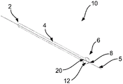
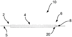
Fig. 1 shows a side view of a surgical drill 10 for bone drills according to an embodiment of the present invention. An isometric view of the drill bit 10 is shown in fig. 2.
The drill bit 10 has a longitudinal axis, which is shown in fig. 1 and 2 by the dashed line labeled 5. The drill bit 10 also has a shaft 4. The shaft 4 may be elongate. The shaft 4 extends along a longitudinal axis 5. The shaft has a proximal end 2. The proximal end may be attached to a bone drill. The proximal end 2 may form a handle as shown in fig. 1 and 2. To attach the drill bit 10 to a bone drill, the shank may be received in a chuck of the bone drill. The drill bit 10 also includes a distal end. As shown, the drill bit 10 has a head 6 at the distal end of the shaft 4. The head 6 may be used to drill into the surface of the bone, typically by pressing the head 6 against the bone, in a direction along the longitudinal axis 5.
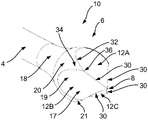
Fig. 3 shows a detailed view of the head 6 of the drill bit 10.
The head 6 has a pointed distal tip 8. When the drill bit 10 drills into it, the pointed distal tip 8 encounters the surface of the bone, typically as a first part of the drill bit 10. The pointed distal tip 8 may be generally sharp to aid in the entry of the head 6 into the bone.
The head 6 further comprises a plurality of grooves 12. In the present example, the head 6 includes four recesses 12A, 12B, 12C, 12D, but it is envisaged that a greater or lesser number of recesses 12 may be provided. Each groove 12A, 12B, 12C, 12D is positioned circumferentially around the head 6. For example, the grooves 12A, 12B, 12C, 12D may be evenly spaced around the circumference of the head 6.
Each groove 12A, 12B, 12C, 12D includes a distal portion 17 and a proximal portion 19. As best seen in fig. 3, each distal portion 17 of each groove 12A, 12B, 12C, 12D extends proximally from the pointed distal tip 8. As also shown in fig. 3, the edges of the distal portions 17 of adjacent pairs of the grooves 12A, 12B, 12C, 12D meet to define a plurality of cutting edges 30. The cutting edges 30 each extend proximally from the pointed distal tip 8. For example, in the present example, the edges of the first pair of grooves 12A, 12B meet to form a first cutting edge 30, the edges of the second pair of grooves 12B, 12C meet to form a second cutting edge 30, the edges of the third pair of grooves 12C, 12D meet to form a third cutting edge 30, and the edges of the fourth pair of grooves 12D, 12A meet to form a fourth cutting edge 30.
In the present example, the surface of each groove 12A, 12B, 12C, 12D has the shape of a partial cylinder (discussed in more detail below in connection with fig. 4). The cylindrical shape of the surface of the grooves 12A, 12B, 12C, 12D produces a concave cutting edge, as shown in fig. 3. This curvature of the cutting edge 30 results in a somewhat sharp tip, since the angle of the cutting edge 30 relative to the longitudinal axis 5 decreases at a position closer to the sharp distal tip 8.
In use, the cutting edges 30 are rotated about the longitudinal axis 5, cutting into the bone as they do so. The grooves 12A, 12B, 12C, 12D are generally used to distribute bone that has been cut by the cutting edge 30 to the rear of the head 6, thereby providing space for additional bone to be removed.
The head 6 also includes a bone contacting outer surface 20. The bone contacting outer surface 20 has a curved portion 21 that curves inwardly toward the longitudinal axis 5 as it approaches the pointed distal tip 8. The curvature of the curved portion 21 of the bone contacting outer surface 20, as viewed in a plane containing the longitudinal axis 5, may be substantially circular. The proximal portion 19 of each groove 12A, 12B, 12C, 12D extends proximally across the curved portion 21 of the bone contacting outer surface 20, as shown in FIG. 3. The edge 32 between the proximal portions 19 of each groove 12A, 12B, 12C, 12D may be curved (e.g., substantially elliptical).
The inward curved portion 21 of the bone contacting outer surface 20 across which the proximal portion 19 of each groove 12A, 12B, 12C, 12D extends may act to inhibit lateral removal of bone by the head 6 as the drill bit 10 is moved laterally within the bone. This may allow the surgeon to use the drill 10 more safely and accurately, especially if he or she wishes to avoid any lateral drilling/cutting of the bone by the head 6.
In particular, because the proximal portion 19 of each groove 12A, 12B, 12C, 12D extends proximally across the curved portion 21 of the bone contacting outer surface 20, the edges 32 of these portions 19 of the grooves 12A, 12B, 12C, 12D may be relatively shallow, particularly as compared to the cutting edges 30. Thus, the edge 32 may not be able to cut laterally into the surface of the bone as the drill is rotated about the longitudinal axis 5. In addition, the curvature of the bone contacting outer surface 20 may present a rounded surface at the side of the head 6, which may inhibit the head 6 from laterally removing bone even when the drill bit is rotated in a plane containing the longitudinal axis 5, as described below in connection with fig. 6.
As can be seen in fig. 3, in the present example, respective adjacent pairs 12A, 12B of grooves 12; 12B, 12C; 12C, 12D; 12D, 12A are separated from one another by respective portions 34 of the curved portion 21 of the bone contacting outer surface 20. Each respective portion 34 of the curved portion 21 of the bone contacting outer surface 20 may be substantially V-shaped. The apex 36 of each substantially V-shaped portion 34 may interface with the proximal end of the cutting edge 30 defined by the respective adjacent pair 12A, 12B of grooves 12; 12B, 12C; 12C, 12D; 12D, 12A is defined by the edges of the distal portion 17. It is noted that since the curved portion 20 of the bone contacting outer surface 21 curves inwardly toward the longitudinal axis 5 as it approaches the pointed distal tip 8, the apex 36 becomes less prominent at the lateral sides of the head 6 than would otherwise be the case. This can significantly reduce the tendency of the head 6 to cut laterally into the bone when the drill is moved laterally (e.g., rotated in a plane containing the longitudinal axis 5).
In the present example, the bone contacting outer surface 20 further comprises a proximal portion that curves inwardly toward the longitudinal axis 5 with increasing distance from the pointed distal tip 8, thereby forming the neck 18 of the surgical drill 10. The neck 18 is located proximal to the head 6. In such examples, the shaft 4 of the surgical drill 10 may be narrower than the head 6. This has the following potential benefits: providing space to the rear of the head 6 to receive bone material dispensed there by the grooves. In this regard, it is noted that it is contemplated that the proximal portion 19 of each groove 12A, 12B, 12C, 12D can extend proximally across a proximal portion of the bone contacting outer surface 20, as shown in fig. 3. It is also contemplated that the relatively narrow shaft 4 may include a flexible portion, thereby allowing the drill bit 10 to travel around one or more bends in the interior of the bone.
Fig. 4 shows a stage in the manufacture of the surgical drill of fig. 1 to 3 prior to the formation of the recesses 12A, 12B, 12C, 12D. It is contemplated that the same or similar methods may be used to manufacture other surgical rotary cutting tools such as rotary initiator devices (also known as tube initiator tips) or straight reamers.
To form the drill bit 10, a workpiece including the shaft 4 of the drill bit 10 may first be provided, having a head portion 46. In this example, the head portion has a curved outer surface, the remainder of which (i.e., after formation of the grooves 12A, 12B, 12C, 12D) will subsequently form the bone contacting outer surface 20 of the drill. The first portion 54 of the curved outer surface may be substantially spherical. After forming the grooves 12A, 12B, 12C, 12D, the remaining portion of the distal portion of the first portion 54 of the curved outer surface may then form the curved portion 21 of the bone contacting outer surface 20 that curves inwardly toward the longitudinal axis 5 as it approaches the pointed distal tip 8. The proximal portion of the first portion 54 and the second portion 58 of the curved outer surface of the head portion 46 may then together form the neck 18 of the drill bit 10.
The head portion 46 may also include a distal tapered portion 56. A distal tapered portion 56 may extend distally from the first portion 54 of the curved outer surface of the head portion 46. The apex 48 of the distal conical portion 56 may lie on the longitudinal axis 5. After forming the flutes 12A, 12B, 12C, 12D, the remainder of the distal tapered portion 56 (possibly including the apex 48) may then form the distal pointed tip 8 of the drill bit 10.
To form the grooves 12 of the drill bit 10, a tool, such as a cylindrical mill or a ball nose mill, may be used to remove material from the head portion 46.
For example, the use of a cylindrical milling cutter can produce a groove 12 having a concave surface and a part-cylindrical shape. Each groove 12 may be cut once by a cylindrical milling cutter, with each cut being spaced circumferentially around the head portion 46 at a location corresponding to the desired location of the groove 12. The cylindrical mill may be oriented at an angle θ relative to the longitudinal axis 5. Thus, the cylindrical axis of the concave cylindrical surface of each groove 12 may be oriented at an angle in the range of 20 ≦ θ ≦ 80 relative to the longitudinal axis 5. It is contemplated that a ball nose mill could alternatively be used to form the recess 12 having a concave surface and a partial cylindrical shape.
As previously mentioned, it is contemplated that the grooves may have a concave cross-sectional shape other than a partial cylinder. For example, the concave surface may be V-shaped (with the apex of the "V" pointing inward, toward the longitudinal axis 5) or square. These and other cross-sectional shapes for the concave surface of the groove may be manufactured using an end mill. The axes of these flutes, similar to the cylindrical axes described above, may be oriented at an angle in the range of 20 ≦ θ ≦ 80 relative to the longitudinal axis 5 of the drill bit.
Although in the example shown in the figures, the path of each groove 12 is substantially straight as each groove 12 extends proximally from the distal tip 8, it is also contemplated that the path may be curved. For example, the path may be substantially helical and/or may curve towards or away from the longitudinal axis 5.
It is also contemplated that each groove 12 may be sloped or angled in one direction to create edges with different angles on either side of the channel formed by each groove 12. This may allow the cutting edge of each flute 12 to have a preferential rotational cutting direction compared to the opposite rotational direction. Furthermore, the groove shape or inclination may be varied over the entire surface of the head 6 to further vary the edge angle.
Fig. 5A to 5D show a plurality of views (cross-sections) of the surgical drill 10 of the drill of fig. 1 to 3, each cross-section being taken in a plane perpendicular to the longitudinal axis 5.
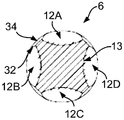
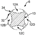
Fig. 5A shows a distal view of the head 6. As can be seen in FIG. 5A, the drill bit 10 in this example includes four flutes 12A, 12B, 12C, 12D positioned circumferentially at 90 intervals around the head 6. Thus, the drill bit 10 includes four cutting edges 30 also positioned at 90 ° intervals around the head 6. The V-shaped corresponding portions 34 of the curved portion 21 of the bone contacting outer surface 20 are also visible in fig. 5A, which shows how these portions 34 curve inwardly towards the longitudinal axis 5 as they approach the pointed distal tip 8, so that the apex 36 is less protruding.
Fig. 5B shows a cross-section through the head 6 at a location along the longitudinal axis 5 between the pointed distal tip 8 and the apex 36. The curved (e.g., substantially cylindrical) shape 13 of the surface of the grooves 12A, 12B, 12C, 12D is visible in fig. 5B.
Fig. 5C shows a cross-section through head 6 at a location along longitudinal axis 5 proximal to apex 36. The curved (e.g., substantially cylindrical) shape 13 of the surface of the grooves 12A, 12B, 12C, 12D is again visible in fig. 5C.
Fig. 5D shows a cross-section through head 6 at a location along longitudinal axis 5 that is further proximal to apex 36 relative to the cross-section of fig. 5C. The curved (e.g., substantially cylindrical) shape 13 of the surface of the grooves 12A, 12B, 12C, 12D is again visible in fig. 5C.
In some examples, the drill bit may include a plurality of additional cutting edges 38 on the shaft 4 intermediate the head 6 and the proximal end 2. These additional cutting edges 38 may be used to cut laterally into the bone at a location located proximally relative to the head 6. An example of using the drill bit 10 including the additional cutting edge 38 will now be described in connection with FIG. 6.
As can be seen in fig. 6, the drill bit in this example is substantially as described above with respect to fig. 1 to 5, with the addition of a plurality of further cutting edges 38. It is envisaged that the drill bit may be substituted for the kind described below with respect to figures 7 to 11 (again, with the addition of an additional cutting edge 38 on the shaft 4).
To use the further cutting edges 38, they may be pushed laterally against the surface of the bone, as schematically indicated by the arrow marked B in fig. 6. Typically, this may be done after the head 8 has been used to drill into the bone in a direction parallel to the longitudinal axis 5, as indicated by the arrow marked a in fig. 6. In some examples, the additional cutting edge 38 may be used to widen the initial opening in the bone made by the head 6. When the lateral movement B is performed to push the further cutting edge 38 laterally against the surface of the bone, it will be appreciated that the head 6 may be located inside the bone.
As described above, the head 6 of the drill bit 10 is configured such that the drill bit does not cut laterally into the bone when the drill bit is moved laterally. Where the drill bit 10 includes an additional cutting edge 38 for cutting laterally into bone at a location located proximally relative to the head 6, the fact that the head 6 is so configured may ensure that the additional cutting edge 38 is allowed, as it is known that this is less likely to result in an undesirable lateral cutting of the head 6.
In one particular example, a surgical rotary cutting tool, such as the drill 10, may be used to prepare a femur to receive the stem of a femoral prosthesis during a hip replacement procedure. In this example, after resecting the head and neck of the femur, the proximal cutting surface of the femur is drilled through using a drill bit having a surgical drill bit 10 of the kind described above attached thereto to gain access to the medullary canal. The surgeon may then position the drill bit 10 such that the head 6 is inside the medullary canal and the additional cutting edge 38 is at the entrance of the medullary canal. The additional cutting edge 38 may then be used to remove bone from the medullary canal by moving the drill bit 10 laterally, as described with respect to fig. 6. This may allow the medullary canal to be shaped to receive the stem. For example, additional cutting edges 38 may be used to widen the entrance to the medullary canal. In one example, the additional cutting edge 38 may be used to remove a portion of the piriformis fossa and/or at least a portion of the larger trochanter that remains after removal of the femoral neck and head. When an additional cutting edge 38 is used as described above, the head 6 may be located inside the medullary canal. As discussed above, the configuration of the head 6 may allow for effective use of the additional cutting edge 38 without causing unwanted lateral removal of bone from the medullary canal by the head 6.
Fig. 7 shows a side view of a surgical drill 10 for bone drills according to another embodiment of the present invention. An isometric view of the drill bit 10 is shown in fig. 8. Fig. 9 shows a detailed view of the head 6 of the drill bit 10.
The drill bit in this example is similar to that described above in connection with fig. 1 to 5, except that it does not include a narrow neck 18 of the kind included in this earlier example. Thus, in this example, the bone contacting outer surface 20 does not include a proximal portion that curves inwardly toward the longitudinal axis 5 with increasing distance from the pointed distal tip 8 (thereby forming a neck 18 of the kind shown in the embodiment of fig. 3). Conversely, the curved portion 21 of the bone contacting outer surface 20 (which curves inwardly toward the longitudinal axis 5 as it approaches the pointed distal tip 8) may terminate proximally at the base of the head where it meets the outer surface of the shaft 4.
In other respects, the construction of the head 6 in the embodiment of fig. 7-9 may be similar to that described above in connection with the embodiment of fig. 1-3.
Fig. 10 shows a stage in the manufacture of the surgical drill of fig. 7-9 prior to the formation of the recesses 12A, 12B, 12C, 12D. Likewise, it is contemplated that the same or similar methods may be used to manufacture other surgical rotary cutting tools such as rotary initiator devices (also known as tube initiator tips) or straight reamers.
To form the drill bit 10, a workpiece including the shaft 4 of the drill bit 10 may first be provided, having a head portion 66. In this example, the head portion 66 has a curved outer surface 64, the remainder of which (i.e., after the grooves 12A, 12B, 12C, 12D are formed) will subsequently form the curved portion 21 of the bone contacting outer surface 20 of the drill 10. The curved outer surface 64 may be substantially spherical (i.e., it may correspond in shape to a portion of the surface of a sphere).
The head portion 66 may also include a distal tapered portion 66. A distal tapered portion 66 may extend distally from the curved outer surface 64. The apex 48 of the distal conical portion 66 may lie on the longitudinal axis 5. After forming the flutes 12A, 12B, 12C, 12D, the remainder of the distal tapered portion 66 (possibly including the apex 48) may then form the distal pointed tip 8 of the drill bit 10.
Starting from the workpiece shown in fig. 10, a cylindrical milling cutter or a ball nose milling cutter may be used to form the recesses 12, substantially as described above in relation to fig. 4, resulting in a drill 10 of the kind shown in fig. 7 to 9. Also, in embodiments where the grooves 12 are V-shaped or square, an end mill may then be used instead to form the grooves 12.
Fig. 11A to 11D show a plurality of views (cross-sections) of the surgical drill 10 of the drill of fig. 7 to 9, each cross-section being taken in a plane perpendicular to the longitudinal axis 5. The views (cross-sections) in fig. 11A to 11D are at the same positions along the longitudinal axis 5 as those in fig. 5A to 5D. A comparison of the views in fig. 5A-5D with the views in fig. 11A-11D shows that the head 6 of the drill bit 10 of this second embodiment is similarly configured as the head 6 in the first embodiment, at least at a location distal to the proximal end of the curved portion 21.
The surgical rotary cutting tools described herein may comprise a material such as stainless steel. By way of example, 400 or 600 series stainless steel cold (e.g., 17/4PH (600 series); 420S 29/S45; 440B or 440C) may be used.
Embodiments of the present invention may allow for the functionality of a pointed tip for initial drilling into bone, as well as the functionality of a lateral reamer combined in a single tool. This may save manufacturing costs for producing surgical instruments for performing surgical procedures and may reduce the weight and size of surgical kits incorporating drill bits.
According to embodiments of the present invention, a surgical kit may be provided. The kit may for example be a kit for hip replacement surgery. The kit may include a plurality of surgical rotary cutting tools (e.g., drills) of the kind described above. It is contemplated that some surgical rotary cutting tools may have different sizes.
Thus, a surgical rotary cutting tool, a surgical kit and a method of preparing a femur to receive a stem of a femoral prosthesis have been described. The tool includes a longitudinal axis and a shaft extending along the longitudinal axis, the shaft having a proximal end and a distal end. The tool also includes a head located at the distal end of the shaft. The head includes a pointed distal tip, a bone contacting outer surface having a portion that curves inwardly toward the longitudinal axis as it approaches the tip, and a plurality of flutes. Edges of the distal portions of adjacent pairs of the grooves meet to define a plurality of cutting edges extending proximally from the pointed distal tip. A proximal portion of each groove extends proximally across the curved portion.
Although particular embodiments of the present invention have been described, it should be understood that many modifications/additions and/or additions may be made within the scope of the invention as claimed.
Claims (14)
1. A surgical rotary cutting tool (10), comprising:
a longitudinal axis (5);
a shaft (4) extending along the longitudinal axis and having a proximal end (2) and a distal end; and
a head (6) located at the distal end of the shaft, the head comprising:
a pointed distal tip (8);
a bone contacting outer surface (20) having a curved portion (21) that curves inwardly toward the longitudinal axis as it approaches the tip; and
a plurality of grooves (12A, 12B, 12C, 12D) positioned circumferentially about the head, wherein each groove comprises a concave cylindrical surface, wherein each groove comprises a proximal portion (19) and a distal portion (17), wherein each distal portion extends proximally from the pointed distal tip, wherein edges of adjacent pairs of the distal portions of the circumferentially positioned grooves meet to define a plurality of cutting edges (30) extending proximally from the pointed distal tip, and wherein the proximal portion of each groove extends proximally across the curved portion of the bone contacting outer surface.
2. The surgical rotary cutting tool of any preceding claim, comprising a plurality of further cutting edges (38) on the shaft intermediate the head and the proximal end of the shaft.
3. The surgical rotary cutting tool of claim 1 or claim 2, wherein the edges of the distal portions of the adjacent pairs of grooves meet to define one or more angles of the plurality of cutting edges that are sharper than one or more angles at the edges formed between the proximal portion of each groove and the bone contacting outer surface.
4. The surgical rotary cutting tool of any preceding claim, wherein the cutting edge extending proximally from the pointed distal tip is concave.
5. The surgical rotary cutting tool of any preceding claim, wherein the axis of the concave cylindrical surface of each groove is oriented at an angle in the range of 20 ° ≦ θ ≦ 80 ° relative to the longitudinal axis.
6. The surgical rotary cutting tool of any preceding claim, wherein the proximal portions of respective adjacent pairs of grooves are separated from each other by respective portions of the curved portion of the bone contacting outer surface.
7. The surgical rotary cutting tool of claim 6, each respective one of the curved portions of the bone contacting outer surface being substantially V-shaped, and wherein an apex (36) of each substantially V-shaped portion interfaces with a proximal end of the cutting edge defined by the respective adjacent pair of grooves.
8. The surgical rotary cutting tool of any preceding claim, wherein the bone contacting outer surface has a proximal portion that curves inwardly toward the longitudinal axis with increasing distance from the pointed distal tip to form a neck of the surgical rotary cutting tool.
9. The surgical rotary cutting tool of claim 8, wherein the proximal portion of each groove extends proximally across the proximal portion of the bone contacting outer surface.
10. The surgical rotary cutting tool of any preceding claim, wherein at least a portion of the bone contacting outer surface is substantially spherical.
11. The surgical rotary cutting tool of any preceding claim, wherein the grooves are equally spaced circumferentially around the head.
12. The surgical rotary cutting tool of any preceding claim comprising four said grooves.
13. The surgical rotary cutting tool of any preceding claim, wherein the tool is a surgical drill bit, a rotary initiator device, or a straight reamer.
14. A surgical kit comprising a plurality of surgical rotary cutting tools (10) according to any preceding claim, wherein at least one of the surgical rotary cutting tools has a different size than at least one other of the surgical rotary cutting tools.
Priority Applications (1)
| Application Number | Priority Date | Filing Date | Title |
|---|---|---|---|
| CN202210181757.XA CN114601524A (en) | 2017-02-14 | 2018-01-24 | Surgical rotary cutting tool |
Applications Claiming Priority (3)
| Application Number | Priority Date | Filing Date | Title |
|---|---|---|---|
| GBGB1702404.3A GB201702404D0 (en) | 2017-02-14 | 2017-02-14 | A surgical rotational cutting tool and method |
| GB1702404.3 | 2017-02-14 | ||
| PCT/EP2018/051682 WO2018149602A1 (en) | 2017-02-14 | 2018-01-24 | A surgical rotational cutting tool |
Related Child Applications (1)
| Application Number | Title | Priority Date | Filing Date |
|---|---|---|---|
| CN202210181757.XA Division CN114601524A (en) | 2017-02-14 | 2018-01-24 | Surgical rotary cutting tool |
Publications (2)
| Publication Number | Publication Date |
|---|---|
| CN110300555A CN110300555A (en) | 2019-10-01 |
| CN110300555B true CN110300555B (en) | 2022-07-29 |
Family
ID=58462142
Family Applications (2)
| Application Number | Title | Priority Date | Filing Date |
|---|---|---|---|
| CN202210181757.XA Pending CN114601524A (en) | 2017-02-14 | 2018-01-24 | Surgical rotary cutting tool |
| CN201880011902.1A Active CN110300555B (en) | 2017-02-14 | 2018-01-24 | Surgical rotary cutting tool |
Family Applications Before (1)
| Application Number | Title | Priority Date | Filing Date |
|---|---|---|---|
| CN202210181757.XA Pending CN114601524A (en) | 2017-02-14 | 2018-01-24 | Surgical rotary cutting tool |
Country Status (7)
| Country | Link |
|---|---|
| US (1) | US11160566B2 (en) |
| EP (2) | EP3582700B1 (en) |
| JP (2) | JP6992078B2 (en) |
| CN (2) | CN114601524A (en) |
| AU (2) | AU2018220755B2 (en) |
| GB (1) | GB201702404D0 (en) |
| WO (1) | WO2018149602A1 (en) |
Families Citing this family (3)
| Publication number | Priority date | Publication date | Assignee | Title |
|---|---|---|---|---|
| GB201702404D0 (en) * | 2017-02-14 | 2017-03-29 | Depuy Ireland Ultd Co | A surgical rotational cutting tool and method |
| CN110840516A (en) * | 2019-12-02 | 2020-02-28 | 北京市春立正达医疗器械股份有限公司 | Hole opening tool bit and hole opening device using same |
| USD956222S1 (en) | 2020-08-21 | 2022-06-28 | Stryker European Operations Limited | Surgical bur assembly |
Citations (3)
| Publication number | Priority date | Publication date | Assignee | Title |
|---|---|---|---|---|
| CN201422900Y (en) * | 2009-06-29 | 2010-03-17 | 中国人民解放军第一零五医院 | Acetabular fossa trigone drill bit for artificial hip replacement |
| CN102510738A (en) * | 2009-08-26 | 2012-06-20 | 史赛克爱尔兰公司 | Ribbed surgical bur |
| CN103690220A (en) * | 2013-12-18 | 2014-04-02 | 无锡雨田精密工具有限公司 | Medical reamer |
Family Cites Families (27)
| Publication number | Priority date | Publication date | Assignee | Title |
|---|---|---|---|---|
| CA1060744A (en) * | 1975-09-05 | 1979-08-21 | Vernon H. Troutner | Wire inserter and sterile wire pack |
| DE19850980C2 (en) | 1998-11-05 | 2000-11-16 | Aesculap Ag & Co Kg | Reamer to prepare a bone cavity |
| EP1253862A4 (en) * | 1999-02-01 | 2003-09-17 | Garland U Edwards | Surgical reamer cutter |
| EP2399530B1 (en) | 2002-08-08 | 2018-11-21 | Surgibit Ip Holdings Pty Limited | A drill bit |
| DE10243104A1 (en) | 2002-09-17 | 2004-03-25 | Gebr. Brasseler Gmbh & Co. Kg | Rotating ceramic tool with a ceramic cutting head bonded to a ceramic or metal support shaft |
| CA2615969A1 (en) | 2005-07-19 | 2007-01-25 | Stryker Ireland Limited | Surgical bur with anti-chatter flute geometry |
| US20080132929A1 (en) | 2005-07-19 | 2008-06-05 | O'sullivan Denis F | Surgical bur with anti-chatter flute geometry |
| JP5233392B2 (en) | 2008-04-30 | 2013-07-10 | 東洋インキScホールディングス株式会社 | Polyurethane polyurea adhesive, curable electromagnetic wave shielding adhesive film using the same, and method for producing the same |
| US8029509B2 (en) * | 2006-03-07 | 2011-10-04 | Orthohelix Surgical Designs, Inc. | Countersink for use in orthopedic surgery |
| CA2669737A1 (en) * | 2006-11-22 | 2008-05-29 | Sonoma Orthopedic Products, Inc. | Surgical tools for use in deploying bone repair devices |
| US8460298B2 (en) * | 2007-08-15 | 2013-06-11 | Stryker Ireland Ltd. | Surgical bur with unequally spaced flutes, flutes with different rake angles and flutes with alternating reliefs |
| JP5871899B2 (en) * | 2010-03-24 | 2016-03-01 | スミス アンド ネフュー インコーポレーテッド | Arthroscopic resection device |
| US20110319895A1 (en) | 2010-06-25 | 2011-12-29 | Depuy Mitek, Inc. | Fluted bone awl and method of use |
| MX344606B (en) * | 2011-03-11 | 2016-12-20 | Smith & Nephew Inc | Trephine. |
| US9326778B2 (en) * | 2011-03-23 | 2016-05-03 | Huwais IP Holding LLC | Autografting osteotome |
| CN103648431B (en) * | 2011-07-06 | 2017-05-17 | 诺贝尔生物服务公司 | Screw and driver composite part |
| US9232952B2 (en) * | 2012-04-16 | 2016-01-12 | Medtronic Ps Medical, Inc. | Surgical bur with non-paired flutes |
| US9226756B2 (en) | 2012-05-14 | 2016-01-05 | DePuy Synthes Products, Inc. | Bone access instrument |
| JP2015527153A (en) * | 2012-09-07 | 2015-09-17 | ストライカー・アイルランド・リミテッド | Surgical bar with a blade groove having a rake face that varies both in helix angle and rake angle |
| GB2509739A (en) * | 2013-01-11 | 2014-07-16 | Nobel Biocare Services Ag | Dental drill bit with spherical head and helical fluting |
| KR20150126615A (en) | 2013-03-12 | 2015-11-12 | 스미스 앤드 네퓨, 인크. | Retro guidewire reamer |
| US9883873B2 (en) * | 2013-07-17 | 2018-02-06 | Medtronic Ps Medical, Inc. | Surgical burs with geometries having non-drifting and soft tissue protective characteristics |
| US20150127005A1 (en) * | 2013-11-06 | 2015-05-07 | DePuy Synthes Products, LLC | Clavicle reamer |
| US10335166B2 (en) * | 2014-04-16 | 2019-07-02 | Medtronics Ps Medical, Inc. | Surgical burs with decoupled rake surfaces and corresponding axial and radial rake angles |
| JP6341506B2 (en) * | 2014-06-24 | 2018-06-13 | 長田電機工業株式会社 | Cutting tools and bone surgery instruments |
| US9955981B2 (en) * | 2015-03-31 | 2018-05-01 | Medtronic Xomed, Inc | Surgical burs with localized auxiliary flutes |
| GB201702404D0 (en) * | 2017-02-14 | 2017-03-29 | Depuy Ireland Ultd Co | A surgical rotational cutting tool and method |
-
2017
- 2017-02-14 GB GBGB1702404.3A patent/GB201702404D0/en not_active Ceased
-
2018
- 2018-01-24 CN CN202210181757.XA patent/CN114601524A/en active Pending
- 2018-01-24 EP EP18702449.2A patent/EP3582700B1/en active Active
- 2018-01-24 EP EP21177604.2A patent/EP3912570B1/en active Active
- 2018-01-24 JP JP2019543862A patent/JP6992078B2/en active Active
- 2018-01-24 WO PCT/EP2018/051682 patent/WO2018149602A1/en unknown
- 2018-01-24 AU AU2018220755A patent/AU2018220755B2/en active Active
- 2018-01-24 US US16/485,494 patent/US11160566B2/en active Active
- 2018-01-24 CN CN201880011902.1A patent/CN110300555B/en active Active
-
2021
- 2021-12-08 JP JP2021199197A patent/JP7210688B2/en active Active
- 2021-12-15 AU AU2021286311A patent/AU2021286311B2/en active Active
Patent Citations (3)
| Publication number | Priority date | Publication date | Assignee | Title |
|---|---|---|---|---|
| CN201422900Y (en) * | 2009-06-29 | 2010-03-17 | 中国人民解放军第一零五医院 | Acetabular fossa trigone drill bit for artificial hip replacement |
| CN102510738A (en) * | 2009-08-26 | 2012-06-20 | 史赛克爱尔兰公司 | Ribbed surgical bur |
| CN103690220A (en) * | 2013-12-18 | 2014-04-02 | 无锡雨田精密工具有限公司 | Medical reamer |
Also Published As
| Publication number | Publication date |
|---|---|
| AU2021286311B2 (en) | 2023-03-30 |
| AU2018220755A1 (en) | 2019-08-08 |
| EP3582700A1 (en) | 2019-12-25 |
| JP2020506018A (en) | 2020-02-27 |
| EP3912570A1 (en) | 2021-11-24 |
| JP7210688B2 (en) | 2023-01-23 |
| WO2018149602A1 (en) | 2018-08-23 |
| US11160566B2 (en) | 2021-11-02 |
| AU2021286311A1 (en) | 2022-01-20 |
| US20200046378A1 (en) | 2020-02-13 |
| EP3582700B1 (en) | 2021-06-09 |
| EP3912570B1 (en) | 2022-10-05 |
| CN110300555A (en) | 2019-10-01 |
| JP2022022369A (en) | 2022-02-03 |
| JP6992078B2 (en) | 2022-01-13 |
| GB201702404D0 (en) | 2017-03-29 |
| AU2018220755B2 (en) | 2022-09-08 |
| CN114601524A (en) | 2022-06-10 |
Similar Documents
| Publication | Publication Date | Title |
|---|---|---|
| AU2021286311B2 (en) | A surgical rotational cutting tool | |
| EP1980216B1 (en) | Articular cartilage repair implant delivery device | |
| EP1563795B1 (en) | Minimally invasive bone miller apparatus | |
| EP2340787B1 (en) | Reciprocating rasp surgical instrument | |
| JP4436252B2 (en) | Reamer assembly | |
| EP3047808B1 (en) | Oscillating surgical rasp | |
| US8523866B2 (en) | Modular tapered hollow reamer for medical applications | |
| EP0570500B1 (en) | Reamer | |
| US7632273B2 (en) | Minimally invasive bone broach | |
| US5931841A (en) | Combination broacher-reamer for use in orthopaedic surgery | |
| EP1535579A2 (en) | Expandable reamer | |
| US8403931B2 (en) | Modular tapered hollow reamer for medical applications | |
| US20220409384A1 (en) | Annular cutting tools for resecting a bone graft and related methods | |
| AU2013231180B2 (en) | Method for surgically implanting a glenoid component | |
| WO2013179002A1 (en) | A trial instrument for use in orthopaedic surgery | |
| AU2011205198A1 (en) | Articular cartilage repair implant delivery device and method of use |
Legal Events
| Date | Code | Title | Description |
|---|---|---|---|
| PB01 | Publication | ||
| PB01 | Publication | ||
| SE01 | Entry into force of request for substantive examination | ||
| SE01 | Entry into force of request for substantive examination | ||
| GR01 | Patent grant | ||
| GR01 | Patent grant |