EP1535579A2 - Expandable reamer - Google Patents
Expandable reamer Download PDFInfo
- Publication number
- EP1535579A2 EP1535579A2 EP04257314A EP04257314A EP1535579A2 EP 1535579 A2 EP1535579 A2 EP 1535579A2 EP 04257314 A EP04257314 A EP 04257314A EP 04257314 A EP04257314 A EP 04257314A EP 1535579 A2 EP1535579 A2 EP 1535579A2
- Authority
- EP
- European Patent Office
- Prior art keywords
- reamer
- blade
- blades
- longitudinal axis
- expanded position
- Prior art date
- Legal status (The legal status is an assumption and is not a legal conclusion. Google has not performed a legal analysis and makes no representation as to the accuracy of the status listed.)
- Withdrawn
Links
Images


Classifications
-
- A—HUMAN NECESSITIES
- A61—MEDICAL OR VETERINARY SCIENCE; HYGIENE
- A61B—DIAGNOSIS; SURGERY; IDENTIFICATION
- A61B17/00—Surgical instruments, devices or methods
- A61B17/16—Instruments for performing osteoclasis; Drills or chisels for bones; Trepans
- A61B17/1613—Component parts
- A61B17/1615—Drill bits, i.e. rotating tools extending from a handpiece to contact the worked material
- A61B17/1617—Drill bits, i.e. rotating tools extending from a handpiece to contact the worked material with mobile or detachable parts
-
- A—HUMAN NECESSITIES
- A61—MEDICAL OR VETERINARY SCIENCE; HYGIENE
- A61B—DIAGNOSIS; SURGERY; IDENTIFICATION
- A61B17/00—Surgical instruments, devices or methods
- A61B17/16—Instruments for performing osteoclasis; Drills or chisels for bones; Trepans
- A61B17/1662—Instruments for performing osteoclasis; Drills or chisels for bones; Trepans for particular parts of the body
- A61B17/1664—Instruments for performing osteoclasis; Drills or chisels for bones; Trepans for particular parts of the body for the hip
- A61B17/1668—Instruments for performing osteoclasis; Drills or chisels for bones; Trepans for particular parts of the body for the hip for the upper femur
-
- A—HUMAN NECESSITIES
- A61—MEDICAL OR VETERINARY SCIENCE; HYGIENE
- A61B—DIAGNOSIS; SURGERY; IDENTIFICATION
- A61B17/00—Surgical instruments, devices or methods
- A61B17/16—Instruments for performing osteoclasis; Drills or chisels for bones; Trepans
- A61B2017/1602—Mills
Definitions
- the blades may be formed from a portion of the cannulated shaft by milling, etching, stamping, or otherwise forming longitudinally oriented slots through the wall of the cannulated shaft, the slots serving as flutes dividing the cutting edge and trailing edge of each adjacent blade.
- Each blade may be segmented along its length, the segments separated at a point of deformation. The location of deformation points provide a desired shape to the cutting surfaces when the reamer body is placed in the expanded position.
- an expandable reamer of the present invention includes a cannulated shaft defining a shank and a reamer body.
- the reamer body defines a plurality of blades having longitudinally extending slots therebetween and an end cutter disposed at the distal end of the reamer body. Distal ends of the blades may be coupled to a ring on which the end cutter is positioned. Proximate ends of the blades are coupled to the shank.
- the blades may be deformable at the point of coupling with the ring and shank. The length of the blade may be divided into two or more segments, the segments separated by a deformation point.
- the blades are easily and inexpensively formed from a reamer body having a polygonal cross-section, such as a hexagon.
- the slots may be milled parallel to and coincident with the apex formed between adjacent sides of the polygon.
- a reamer according to the present invention includes a cannulated shaft having a wall, a proximate end and a distal end and defining a longitudinal axis, the cannulated shaft having a plurality of slots therethrough, the plurality of slots extending from the distal end toward the proximate end, and a plurality of blades, each one of the plurality of blades defined by the wall between adjacent ones of the plurality of slots.
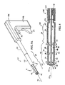
- proximal segment 88 of each blade 40 is joined to shank 28.
- Deformation points 87 are formed by proximal exterior circumferential relief 94 cut in land 80 of each blade 40.
- deformation points 87 are located in blade 40 where distal segment 90 of each blade 40 is connected to distal ring 42 of reamer body 30.
- Deformation points 87 may be formed by distal exterior circumferential relief 96 cut in each land of blade 40.
- radially oriented arcuate notches 95 (Fig. 1) may be cut in blades 40 along cutting edge 72 and coincident with reliefs 92, 94, and 96, further reducing the resistance of blades 40 to bending to the expanded position.
- rotational drive 110 of driving device 106 may be coupled with chuck end 32 and translational drive 112 may be coupled with elongate member 104.
- first actuator 114 functions to rotate rotational drive 110 and thus reamer 20 about longitudinal axis 26.
- Second actuator 116 functions to translate translational drive 112 and thus elongate member 104 and bushing 102 along longitudinal axis 26.
- second actuator 116 By actuating second actuator 116 in a first direction, bushing 102 is drawn toward distal end 36 of shank 28, thereby deforming blades 42 radially outwardly to the expanded position shown in Fig. 3B.
Landscapes
- Health & Medical Sciences (AREA)
- Surgery (AREA)
- Life Sciences & Earth Sciences (AREA)
- Biomedical Technology (AREA)
- Medical Informatics (AREA)
- Orthopedic Medicine & Surgery (AREA)
- Oral & Maxillofacial Surgery (AREA)
- Engineering & Computer Science (AREA)
- Dentistry (AREA)
- Heart & Thoracic Surgery (AREA)
- Nuclear Medicine, Radiotherapy & Molecular Imaging (AREA)
- Molecular Biology (AREA)
- Animal Behavior & Ethology (AREA)
- General Health & Medical Sciences (AREA)
- Public Health (AREA)
- Veterinary Medicine (AREA)
- Surgical Instruments (AREA)
Abstract
Description
Claims (31)
- A reamer comprising:a shank;a reamer body having a longitudinal axis; anda blade formed in said reamer body, said blade deformable between a contracted position and an expanded position.
- The reamer of claim 1, wherein said shank has a radius measured from said longitudinal axis, said blade in said contracted position extending no further from said longitudinal axis than said radius of said shank.
- The reamer of claim 1, wherein said shank has a radius measured from said longitudinal axis, said blade in said expanded position extending further from said longitudinal axis than said radius of said shank.
- The reamer of claim 1, wherein said blade in said contracted position is substantially parallel to said longitudinal axis.
- The reamer of claim 1, wherein said blade in said expanded position comprises a portion oriented radially outward from said longitudinal axis.
- The reamer of claim 1, wherein said blade comprises at least one deformation point.
- The reamer of claim 6, wherein said at least one deformation point comprises an exterior circumferential relief.
- The reamer of claim 7, wherein said exterior circumferential relief is formed in a proximate end of said blade, said reamer further comprises a ring coupled to a distal end of said blade, and said at least one deformation point further comprises an exterior circumferential relief formed in said distal end of said blade.
- The reamer of claim 6, wherein said at least one deformation point comprises at least one interior circumferential relief formed in said blade between said proximate end and said distal end.
- The reamer of claim 6, wherein said at least one deformation point comprises a radially oriented cut in said blade.
- The reamer of claim 6, wherein said at least one deformation point comprises a thinned region.
- The reamer of claim 1, wherein said reamer body comprises a shaft having a polygonal cross-section, an edge of said blade being coincident with an apex formed by two adjacent sides of said polygonal reamer body.
- The reamer of claim 1, further comprising an actuating means for moving said blade between said contracted position and said expanded position.
- The reamer of claim 13, wherein said shank is cannulated and said actuating means comprises an elongate member connected to said blade, proximate translation of said elongate member moving said blade from said contracted position to said expanded position, and distal translation of said elongate member moving said blade from said expanded position to said contracted position.
- The reamer of claim 1, further comprising an end cutter secured to a distal end of said reamer body.
- The reamer of claim 1, wherein said blade is biased to said expanded position and is collapsible to said contracted position upon application of a radially inward force upon said blade.
- A reamer, comprising:a shank;a reamer body having a longitudinal axis;a blade formed in said reamer body; anddeformation means for deforming said blade between a contracted position and an expanded position.
- The reamer of claim 17, wherein said shank has a radius measured from said longitudinal axis, said blade in said contracted position extending no further from said longitudinal axis than said radius of said shank.
- The reamer of claim 17, wherein said shank has a radius measured from said longitudinal axis, said blade in said expanded position extending further from said longitudinal axis than said radius of said shank.
- The reamer of claim 17, wherein said blade in said contracted position is substantially parallel to said longitudinal axis.
- The reamer of claim 17, wherein said blade in said expanded position comprises a portion oriented radially outward from said longitudinal axis.
- The reamer of claim 17, wherein said reamer body comprises a shaft having a polygonal cross-section, an edge of said blade being coincident with an apex formed by two adjacent sides of said polygonal reamer body.
- The reamer of claim 17, further comprising an actuating means for moving said blade between said contracted position and said expanded position.
- The reamer of claim 23, wherein said shank is cannulated and said actuating means comprises an elongate member connected to said blade, proximate translation of said elongate member moving said blade from said contracted position to said expanded position, and distal translation of said elongated member moving said blade from said expanded position to said contracted position.
- The reamer of claim 17, further comprising an end cutter secured to a distal end of said reamer body.
- The reamer of claim 17, wherein said blade is biased to said expanded position and is collapsible to said contracted position upon application of a radially inward force upon said blade.
- A reamer, comprising:a cannulated shaft having a wall, a proximate end and a distal end, said cannulated shaft defining a longitudinal axis, said wall having a plurality of slots therethrough, said plurality of slots extending from said distal end toward said proximate end; anda plurality of blades, each one of said plurality of blades defined by said wall between adjacent ones of said plurality of slots.
- The reamer of claim 27, wherein each one of said plurality of blades includes at least one segment, adjacent said segments being arranged lengthwise along each one of said plurality of blades.
- The reamer of claim 28, further comprising:a plurality of deformation points coupling adjacent said segments and coupling each one of said plurality of blades to said cannulated shaft;said plurality of blades deformable between a contracted position and an expanded position;said plurality of blades being substantially parallel to said longitudinal axis in said contracted position; andsaid plurality of blades being deformable at said deformation points to achieve said expanded position.
- The reamer of claim 29, wherein a portion of said wall of said shaft in which said plurality of blades are formed has a polygonal cross-section.
- The reamer of claim 27, further comprising an end cutter secured to a distal end of said plurality of blades.
Applications Claiming Priority (2)
| Application Number | Priority Date | Filing Date | Title |
|---|---|---|---|
| US721808 | 2003-11-25 | ||
| US10/721,808 US20050113836A1 (en) | 2003-11-25 | 2003-11-25 | Expandable reamer |
Publications (2)
| Publication Number | Publication Date |
|---|---|
| EP1535579A2 true EP1535579A2 (en) | 2005-06-01 |
| EP1535579A3 EP1535579A3 (en) | 2005-06-15 |
Family
ID=34465674
Family Applications (1)
| Application Number | Title | Priority Date | Filing Date |
|---|---|---|---|
| EP04257314A Withdrawn EP1535579A3 (en) | 2003-11-25 | 2004-11-25 | Expandable reamer |
Country Status (5)
| Country | Link |
|---|---|
| US (1) | US20050113836A1 (en) |
| EP (1) | EP1535579A3 (en) |
| JP (1) | JP2005152650A (en) |
| AU (1) | AU2004233454A1 (en) |
| CA (1) | CA2488225A1 (en) |
Cited By (17)
| Publication number | Priority date | Publication date | Assignee | Title |
|---|---|---|---|---|
| WO2007003243A1 (en) * | 2005-07-05 | 2007-01-11 | Plus Orthopedics Ag | Bone cutter |
| WO2009143496A1 (en) * | 2008-05-22 | 2009-11-26 | Trinity Orthopedics, Llc | Devices and methods for spinal reduction, displacement and resection |
| US8287538B2 (en) | 2008-01-14 | 2012-10-16 | Conventus Orthopaedics, Inc. | Apparatus and methods for fracture repair |
| WO2013101835A1 (en) * | 2011-12-27 | 2013-07-04 | Symmetry Medical, Inc. | Expandable retrograde drill |
| WO2014174521A1 (en) * | 2013-04-24 | 2014-10-30 | T.A.G. Medical Devices - Agriculture Cooperative Ltd. | Bone material removal devices |
| US8906022B2 (en) | 2010-03-08 | 2014-12-09 | Conventus Orthopaedics, Inc. | Apparatus and methods for securing a bone implant |
| US8961518B2 (en) | 2010-01-20 | 2015-02-24 | Conventus Orthopaedics, Inc. | Apparatus and methods for bone access and cavity preparation |
| EP2928390A4 (en) * | 2012-12-10 | 2017-04-12 | The Curators of the University of Missouri | System, apparatus, and method for grafting tissue |
| US9730739B2 (en) | 2010-01-15 | 2017-08-15 | Conventus Orthopaedics, Inc. | Rotary-rigid orthopaedic rod |
| US9980715B2 (en) | 2014-02-05 | 2018-05-29 | Trinity Orthopedics, Llc | Anchor devices and methods of use |
| US10022132B2 (en) | 2013-12-12 | 2018-07-17 | Conventus Orthopaedics, Inc. | Tissue displacement tools and methods |
| US10448959B2 (en) | 2015-04-09 | 2019-10-22 | T.A.G. Medical Devices—Agriculture Cooperative Ltd. | Bone material removal device and a method for use thereof |
| US10537340B2 (en) | 2014-10-19 | 2020-01-21 | T.A.G. Medical Devices—Agriculture Cooperative Ltd. | Kit including a guiding system and a bone material removal device |
| US10660657B2 (en) | 2016-02-11 | 2020-05-26 | T.A.G. Medical Devices—Agriculture Cooperative Ltd. | Bone material removal device and a method for use thereof |
| US10918426B2 (en) | 2017-07-04 | 2021-02-16 | Conventus Orthopaedics, Inc. | Apparatus and methods for treatment of a bone |
| US11020132B2 (en) | 2016-04-24 | 2021-06-01 | T.A.G. Medical Devices—Agriculture Cooperative Ltd. | Guiding device and method of using thereof |
| US11202641B2 (en) | 2018-08-01 | 2021-12-21 | T.A.G. Medical Devices—Agriculture Cooperative Ltd. | Adjustable drilling device and a method for use thereof |
Families Citing this family (105)
| Publication number | Priority date | Publication date | Assignee | Title |
|---|---|---|---|---|
| US7632274B2 (en) * | 2000-02-16 | 2009-12-15 | Trans1 Inc. | Thin cutter blades with retaining film for preparing intervertebral disc spaces |
| US7488329B2 (en) * | 2000-03-07 | 2009-02-10 | Zimmer Technology, Inc. | Method and apparatus for reducing femoral fractures |
| US7485119B2 (en) * | 2000-03-07 | 2009-02-03 | Zimmer Technology, Inc. | Method and apparatus for reducing femoral fractures |
| US20030220646A1 (en) * | 2002-05-23 | 2003-11-27 | Thelen Sarah L. | Method and apparatus for reducing femoral fractures |
| US20060052788A1 (en) * | 2003-02-04 | 2006-03-09 | Thelen Sarah L | Expandable fixation devices for minimally invasive surgery |
| EP2305155A3 (en) | 2003-10-23 | 2015-01-14 | TRANS1, Inc. | Tools and tool kits for performing minimally invasive procedures on the spine |
| US7507241B2 (en) * | 2004-04-05 | 2009-03-24 | Expanding Orthopedics Inc. | Expandable bone device |
| US20090088846A1 (en) * | 2007-04-17 | 2009-04-02 | David Myung | Hydrogel arthroplasty device |
| US7479144B2 (en) * | 2004-12-10 | 2009-01-20 | Symmetry Medical, Inc. | Collapsible orthopaedic reamer |
| US20060178594A1 (en) * | 2005-02-07 | 2006-08-10 | Neubardt Seth L | Apparatus and method for locating defects in bone tissue |
| US20060229624A1 (en) * | 2005-03-31 | 2006-10-12 | Zimmer Technology, Inc. | Orthopaedic cutting instrument and method |
| US20070067034A1 (en) * | 2005-08-31 | 2007-03-22 | Chirico Paul E | Implantable devices and methods for treating micro-architecture deterioration of bone tissue |
| US8998923B2 (en) * | 2005-08-31 | 2015-04-07 | Spinealign Medical, Inc. | Threaded bone filling material plunger |
| CA2626437A1 (en) * | 2005-11-10 | 2007-05-24 | Zimmer, Inc. | Minamally invasive orthopaedic delivery devices and tools |
| US20070276396A1 (en) * | 2006-05-10 | 2007-11-29 | Howmedica Osteonics Corp. | Modular acetabular reamer |
| US8480673B2 (en) * | 2006-06-01 | 2013-07-09 | Osteo Innovations Llc | Cavity creation device and methods of use |
| US20100217335A1 (en) * | 2008-12-31 | 2010-08-26 | Chirico Paul E | Self-expanding bone stabilization devices |
| US8647349B2 (en) * | 2006-10-18 | 2014-02-11 | Hologic, Inc. | Systems for performing gynecological procedures with mechanical distension |
| US9392935B2 (en) | 2006-11-07 | 2016-07-19 | Hologic, Inc. | Methods for performing a medical procedure |
| US8025656B2 (en) | 2006-11-07 | 2011-09-27 | Hologic, Inc. | Methods, systems and devices for performing gynecological procedures |
| US8403931B2 (en) * | 2007-02-09 | 2013-03-26 | Christopher G. Sidebotham | Modular tapered hollow reamer for medical applications |
| US8535316B2 (en) * | 2007-02-09 | 2013-09-17 | Randall J. Lewis | Hollow reamer for medical applications |
| US8357163B2 (en) | 2007-02-09 | 2013-01-22 | Sidebotham Christopher G | Low cost modular tapered and spherical hollow reamers for medical applications |
| US8449545B2 (en) * | 2007-02-09 | 2013-05-28 | Christopher G. Sidebotham | Low cost modular tapered hollow reamer for medical applications |
| US8556897B2 (en) | 2007-02-09 | 2013-10-15 | Christopher G. Sidebotham | Modular spherical hollow reamer assembly for medical applications |
| US8523866B2 (en) | 2007-02-09 | 2013-09-03 | Christopher G. Sidebotham | Modular tapered hollow reamer for medical applications |
| EP2131769B1 (en) * | 2007-03-02 | 2011-04-27 | Spinealign Medical, Inc. | Fracture fixation system |
| US20090270895A1 (en) | 2007-04-06 | 2009-10-29 | Interlace Medical, Inc. | Low advance ratio, high reciprocation rate tissue removal device |
| US9259233B2 (en) | 2007-04-06 | 2016-02-16 | Hologic, Inc. | Method and device for distending a gynecological cavity |
| US9095366B2 (en) | 2007-04-06 | 2015-08-04 | Hologic, Inc. | Tissue cutter with differential hardness |
| US8574253B2 (en) | 2007-04-06 | 2013-11-05 | Hologic, Inc. | Method, system and device for tissue removal |
| US20080275448A1 (en) | 2007-05-02 | 2008-11-06 | Sackett Samuel G | Expandable proximal reamer |
| US7935117B2 (en) * | 2007-05-02 | 2011-05-03 | Depuy Products, Inc. | Expandable proximal reamer |
| US20090276048A1 (en) * | 2007-05-08 | 2009-11-05 | Chirico Paul E | Devices and method for bilateral support of a compression-fractured vertebral body |
| ES2348889T3 (en) * | 2007-05-23 | 2010-12-16 | Stryker Trauma Gmbh | SCARNING DEVICE. |
| US9510885B2 (en) | 2007-11-16 | 2016-12-06 | Osseon Llc | Steerable and curvable cavity creation system |
| US20090131867A1 (en) | 2007-11-16 | 2009-05-21 | Liu Y King | Steerable vertebroplasty system with cavity creation element |
| US20090131886A1 (en) | 2007-11-16 | 2009-05-21 | Liu Y King | Steerable vertebroplasty system |
| US20090177206A1 (en) * | 2008-01-08 | 2009-07-09 | Zimmer Spine, Inc. | Instruments, implants, and methods for fixation of vertebral compression fractures |
| US20090216260A1 (en) * | 2008-02-20 | 2009-08-27 | Souza Alison M | Interlocking handle |
| EP2268331A2 (en) * | 2008-03-21 | 2011-01-05 | Biomimedica, Inc | Methods, devices and compositions for adhering hydrated polymer implants to bone |
| US20120209396A1 (en) | 2008-07-07 | 2012-08-16 | David Myung | Orthopedic implants having gradient polymer alloys |
| US8883915B2 (en) | 2008-07-07 | 2014-11-11 | Biomimedica, Inc. | Hydrophobic and hydrophilic interpenetrating polymer networks derived from hydrophobic polymers and methods of preparing the same |
| EP2297217B1 (en) * | 2008-07-07 | 2021-10-20 | Hyalex Orthopaedics, Inc. | Hydrophilic interpenetrating polymer networks derived from hydrophobic polymers |
| EP2313147A4 (en) * | 2008-07-16 | 2013-05-22 | Spinealign Medical Inc | Morselizer |
| US8497023B2 (en) * | 2008-08-05 | 2013-07-30 | Biomimedica, Inc. | Polyurethane-grafted hydrogels |
| US8246627B2 (en) * | 2008-08-07 | 2012-08-21 | Stryker Corporation | Cement delivery device for introducing cement into tissue, the device having a cavity creator |
| US11903602B2 (en) | 2009-04-29 | 2024-02-20 | Hologic, Inc. | Uterine fibroid tissue removal device |
| US20100298832A1 (en) | 2009-05-20 | 2010-11-25 | Osseon Therapeutics, Inc. | Steerable curvable vertebroplasty drill |
| BR112012001467A2 (en) * | 2009-07-24 | 2016-03-15 | Smith & Nephew Inc | surgical instruments for sectioning cavities in intramedullary canals. |
| CA2787272A1 (en) * | 2009-12-18 | 2011-06-23 | Biomimedica, Inc. | Method, device, and system for shaving and shaping of a joint |
| WO2012151573A1 (en) | 2010-01-04 | 2012-11-08 | Zyga Technology, Inc. | Sacroiliac fusion system |
| US8696672B2 (en) * | 2010-01-22 | 2014-04-15 | Baxano Surgical, Inc. | Abrading tool for preparing intervertebral disc spaces |
| JP4597260B1 (en) * | 2010-03-30 | 2010-12-15 | 宏 黒澤 | Jig for forming implant cavity and surgical tool |
| US9125671B2 (en) | 2010-04-29 | 2015-09-08 | Dfine, Inc. | System for use in treatment of vertebral fractures |
| US8608785B2 (en) | 2010-06-02 | 2013-12-17 | Wright Medical Technology, Inc. | Hammer toe implant with expansion portion for retrograde approach |
| US9724140B2 (en) | 2010-06-02 | 2017-08-08 | Wright Medical Technology, Inc. | Tapered, cylindrical cruciform hammer toe implant and method |
| US9498273B2 (en) | 2010-06-02 | 2016-11-22 | Wright Medical Technology, Inc. | Orthopedic implant kit |
| US9028496B2 (en) * | 2011-04-12 | 2015-05-12 | William L. Tontz | Device for establishing supportive forces in the bony structure of a skeleton |
| EP3357518B1 (en) | 2011-10-03 | 2020-12-02 | Hyalex Orthopaedics, Inc. | Polymeric adhesive for anchoring compliant materials to another surface |
| EP2782524B1 (en) | 2011-11-21 | 2017-12-20 | Biomimedica, Inc | Systems for anchoring orthopaedic implants to bone |
| CA2872238A1 (en) * | 2012-05-03 | 2013-11-07 | Ultimate Joint Ltd. | In-situ formation of a joint replacement prosthesis |
| US9629646B2 (en) | 2012-07-11 | 2017-04-25 | Jens Kather | Curved burr surgical instrument |
| US9011443B2 (en) | 2012-09-20 | 2015-04-21 | Depuy Mitek, Llc | Low profile reamers and methods of use |
| AU2013355313A1 (en) * | 2012-12-05 | 2015-06-11 | Smith & Nephew, Inc. | Surgical instrument |
| US10357259B2 (en) | 2012-12-05 | 2019-07-23 | Smith & Nephew, Inc. | Surgical instrument |
| US8945232B2 (en) | 2012-12-31 | 2015-02-03 | Wright Medical Technology, Inc. | Ball and socket implants for correction of hammer toes and claw toes |
| US9084615B2 (en) | 2013-01-31 | 2015-07-21 | Depuy Mitek, Llc | Methods and devices for removing abnormalities from bone |
| US10105150B2 (en) | 2013-03-12 | 2018-10-23 | Smith & Newphew, Inc. | Retro guidewire reamer |
| WO2014159225A2 (en) | 2013-03-14 | 2014-10-02 | Baxano Surgical, Inc. | Spinal implants and implantation system |
| US9724139B2 (en) | 2013-10-01 | 2017-08-08 | Wright Medical Technology, Inc. | Hammer toe implant and method |
| EP3057517B1 (en) | 2013-10-15 | 2020-04-08 | Stryker Corporation | Device for creating a void space in a living tissue, the device including a handle with a control knob that can be set regardless of the orientation of the handle |
| US9474561B2 (en) | 2013-11-19 | 2016-10-25 | Wright Medical Technology, Inc. | Two-wire technique for installing hammertoe implant |
| US12201332B2 (en) | 2013-12-09 | 2025-01-21 | Acumed Llc | Bone plate with movable joint |
| US11219466B2 (en) * | 2018-06-06 | 2022-01-11 | Acumed Llc | Orthopedic reamer with expandable cutting head |
| US9861375B2 (en) | 2014-01-09 | 2018-01-09 | Zyga Technology, Inc. | Undercutting system for use in conjunction with sacroiliac fusion |
| US9498266B2 (en) | 2014-02-12 | 2016-11-22 | Wright Medical Technology, Inc. | Intramedullary implant, system, and method for inserting an implant into a bone |
| US9545274B2 (en) | 2014-02-12 | 2017-01-17 | Wright Medical Technology, Inc. | Intramedullary implant, system, and method for inserting an implant into a bone |
| US9603607B2 (en) | 2014-03-11 | 2017-03-28 | Lenkbar, Llc | Reaming instrument with adjustable profile |
| US9517076B2 (en) | 2014-03-11 | 2016-12-13 | Lenkbar, Llc | Reaming instrument with adjustable profile |
| US9243881B2 (en) | 2014-05-29 | 2016-01-26 | Smith & Nephew, Inc. | Retrograde reamer depth tub gage |
| US9956015B2 (en) | 2014-07-03 | 2018-05-01 | Acumed Llc | Bone plate with movable joint |
| US20160045207A1 (en) | 2014-08-14 | 2016-02-18 | Biomet Manufacturing, Llc | Flexible bone reamer |
| CN105764449A (en) * | 2014-09-18 | 2016-07-13 | 瑞特医疗技术公司 | Hammertoe implant and instrument |
| US10398416B2 (en) | 2014-10-01 | 2019-09-03 | Smith & Nephew, Inc. | Bone marrow lesion drill |
| AU2014334525B2 (en) | 2014-12-19 | 2017-05-25 | Wright Medical Technology, Inc | Intramedullary anchor for interphalangeal arthrodesis |
| US10080571B2 (en) | 2015-03-06 | 2018-09-25 | Warsaw Orthopedic, Inc. | Surgical instrument and method |
| WO2016168363A1 (en) * | 2015-04-14 | 2016-10-20 | Cartiva, Inc. | Tooling for creating tapered opening in tissue and related methods |
| US11077228B2 (en) | 2015-08-10 | 2021-08-03 | Hyalex Orthopaedics, Inc. | Interpenetrating polymer networks |
| CA3003306C (en) | 2015-11-17 | 2019-04-16 | Lenkbar, Llc | Surgical tunneling instrument with expandable section |
| US10492800B2 (en) | 2015-11-25 | 2019-12-03 | Lenkbar, Llc | Bone cutting instrument with expandable section |
| CN107874805A (en) * | 2016-09-29 | 2018-04-06 | 张国伟 | A kind of reamer |
| EP3531934B1 (en) | 2016-10-27 | 2024-08-21 | Dfine, Inc. | Articulating osteotome with cement delivery channel |
| US9737313B1 (en) | 2016-11-07 | 2017-08-22 | Roger C. Sohn | Shoulder reamer devices, systems including the same, and related methods |
| EP4566556A3 (en) | 2016-11-28 | 2025-09-03 | Dfine, Inc. | Tumor ablation devices and related methods |
| US10470781B2 (en) | 2016-12-09 | 2019-11-12 | Dfine, Inc. | Medical devices for treating hard tissues and related methods |
| EP3565486B1 (en) | 2017-01-06 | 2021-11-10 | Dfine, Inc. | Osteotome with a distal portion for simultaneous advancement and articulation |
| US10456145B2 (en) | 2017-05-16 | 2019-10-29 | Arthrex, Inc. | Expandable reamers |
| US10869950B2 (en) | 2018-07-17 | 2020-12-22 | Hyalex Orthopaedics, Inc. | Ionic polymer compositions |
| EP3876856A4 (en) | 2018-11-08 | 2022-10-12 | Dfine, Inc. | TUMOR REMOVAL DEVICE AND RELATED SYSTEMS AND METHODS |
| EP3958752B1 (en) | 2019-04-24 | 2025-03-12 | Stryker Corporation | Systems for off-axis augmentation of a vertebral body |
| EP4574195A3 (en) | 2019-09-18 | 2025-08-27 | Merit Medical Systems, Inc. | Osteotome with inflatable portion and multiwire articulation |
| WO2022109132A1 (en) * | 2020-11-18 | 2022-05-27 | University Of Washington | Deployable tubular biopsy device |
| CN117102874B (en) * | 2023-08-18 | 2026-03-06 | 东方电气集团东方汽轮机有限公司 | Guide reamer for machining fork pin holes of steam turbine rotor and its application method |
| CN118370569B (en) * | 2024-06-21 | 2024-08-30 | 北京市顺义区妇幼保健院 | Tapping device suitable for minimally invasive surgery |
Family Cites Families (14)
| Publication number | Priority date | Publication date | Assignee | Title |
|---|---|---|---|---|
| US2450223A (en) * | 1944-11-25 | 1948-09-28 | William R Barbour | Well reaming apparatus |
| US3702611A (en) * | 1971-06-23 | 1972-11-14 | Meyer Fishbein | Surgical expansive reamer for hip socket |
| DE8814941U1 (en) * | 1988-12-01 | 1989-02-02 | Lieke, Michael, Dipl.-Ing. Dr., 7835 Teningen | Special milling cutters for use in implant technology |
| US5620450A (en) * | 1992-09-30 | 1997-04-15 | Staar Surgical Company, Inc. | Transverse hinged deformable intraocular lens injecting apparatus |
| US5885258A (en) * | 1996-02-23 | 1999-03-23 | Memory Medical Systems, Inc. | Medical instrument with slotted memory metal tube |
| US6070677A (en) * | 1997-12-02 | 2000-06-06 | I.D.A. Corporation | Method and apparatus for enhancing production from a wellbore hole |
| US6632197B2 (en) * | 1999-04-16 | 2003-10-14 | Thomas R. Lyon | Clear view cannula |
| US6383188B2 (en) * | 2000-02-15 | 2002-05-07 | The Spineology Group Llc | Expandable reamer |
| US6790210B1 (en) * | 2000-02-16 | 2004-09-14 | Trans1, Inc. | Methods and apparatus for forming curved axial bores through spinal vertebrae |
| US20010031981A1 (en) * | 2000-03-31 | 2001-10-18 | Evans Michael A. | Method and device for locating guidewire and treating chronic total occlusions |
| US6676665B2 (en) * | 2000-08-11 | 2004-01-13 | Sdgi Holdings, Inc. | Surgical instrumentation and method for treatment of the spine |
| US6746451B2 (en) * | 2001-06-01 | 2004-06-08 | Lance M. Middleton | Tissue cavitation device and method |
| US6814734B2 (en) * | 2001-06-18 | 2004-11-09 | Sdgi Holdings, Inc, | Surgical instrumentation and method for forming a passage in bone having an enlarged cross-sectional portion |
| US6976547B2 (en) * | 2002-07-16 | 2005-12-20 | Cdx Gas, Llc | Actuator underreamer |
-
2003
- 2003-11-25 US US10/721,808 patent/US20050113836A1/en not_active Abandoned
-
2004
- 2004-11-23 CA CA002488225A patent/CA2488225A1/en not_active Abandoned
- 2004-11-24 AU AU2004233454A patent/AU2004233454A1/en not_active Abandoned
- 2004-11-25 JP JP2004340692A patent/JP2005152650A/en active Pending
- 2004-11-25 EP EP04257314A patent/EP1535579A3/en not_active Withdrawn
Cited By (36)
| Publication number | Priority date | Publication date | Assignee | Title |
|---|---|---|---|---|
| WO2007003243A1 (en) * | 2005-07-05 | 2007-01-11 | Plus Orthopedics Ag | Bone cutter |
| US9517093B2 (en) | 2008-01-14 | 2016-12-13 | Conventus Orthopaedics, Inc. | Apparatus and methods for fracture repair |
| US8287538B2 (en) | 2008-01-14 | 2012-10-16 | Conventus Orthopaedics, Inc. | Apparatus and methods for fracture repair |
| US10603087B2 (en) | 2008-01-14 | 2020-03-31 | Conventus Orthopaedics, Inc. | Apparatus and methods for fracture repair |
| US11399878B2 (en) | 2008-01-14 | 2022-08-02 | Conventus Orthopaedics, Inc. | Apparatus and methods for fracture repair |
| US9788870B2 (en) | 2008-01-14 | 2017-10-17 | Conventus Orthopaedics, Inc. | Apparatus and methods for fracture repair |
| WO2009143496A1 (en) * | 2008-05-22 | 2009-11-26 | Trinity Orthopedics, Llc | Devices and methods for spinal reduction, displacement and resection |
| US9730739B2 (en) | 2010-01-15 | 2017-08-15 | Conventus Orthopaedics, Inc. | Rotary-rigid orthopaedic rod |
| AU2011207550B2 (en) * | 2010-01-20 | 2016-03-10 | Conventus Orthopaedics, Inc. | Apparatus and methods for bone access and cavity preparation |
| EP2523616A4 (en) * | 2010-01-20 | 2015-09-30 | Conventus Orthopaedics Inc | Apparatus and methods for bone access and cavity preparation |
| US8961518B2 (en) | 2010-01-20 | 2015-02-24 | Conventus Orthopaedics, Inc. | Apparatus and methods for bone access and cavity preparation |
| US9848889B2 (en) | 2010-01-20 | 2017-12-26 | Conventus Orthopaedics, Inc. | Apparatus and methods for bone access and cavity preparation |
| US8906022B2 (en) | 2010-03-08 | 2014-12-09 | Conventus Orthopaedics, Inc. | Apparatus and methods for securing a bone implant |
| US9993277B2 (en) | 2010-03-08 | 2018-06-12 | Conventus Orthopaedics, Inc. | Apparatus and methods for securing a bone implant |
| WO2013101835A1 (en) * | 2011-12-27 | 2013-07-04 | Symmetry Medical, Inc. | Expandable retrograde drill |
| EP2928390A4 (en) * | 2012-12-10 | 2017-04-12 | The Curators of the University of Missouri | System, apparatus, and method for grafting tissue |
| US10188403B2 (en) | 2013-04-24 | 2019-01-29 | T.A.G. Medical Devices—Agriculture Cooperative Ltd. | Bone material removal devices |
| US9668750B2 (en) | 2013-04-24 | 2017-06-06 | T.A.G. Medical Devices—Agriculture Cooperative Ltd. | Bone material removal devices |
| WO2014174521A1 (en) * | 2013-04-24 | 2014-10-30 | T.A.G. Medical Devices - Agriculture Cooperative Ltd. | Bone material removal devices |
| US10076342B2 (en) | 2013-12-12 | 2018-09-18 | Conventus Orthopaedics, Inc. | Tissue displacement tools and methods |
| US10022132B2 (en) | 2013-12-12 | 2018-07-17 | Conventus Orthopaedics, Inc. | Tissue displacement tools and methods |
| US9980715B2 (en) | 2014-02-05 | 2018-05-29 | Trinity Orthopedics, Llc | Anchor devices and methods of use |
| US11896242B2 (en) | 2014-10-19 | 2024-02-13 | T.A.G. Medical Products Corporation Ltd. | Kit including a guiding system and a bone material removal device |
| US11033283B2 (en) | 2014-10-19 | 2021-06-15 | T.A.G. Medical Devices—Agriculture Cooperative Ltd. | Kit including a guiding system and a bone material removal device |
| US12310601B2 (en) | 2014-10-19 | 2025-05-27 | T.A.G. Medical Products Corporation Ltd. | Kit including a guiding system and a bone material removal device |
| US10537340B2 (en) | 2014-10-19 | 2020-01-21 | T.A.G. Medical Devices—Agriculture Cooperative Ltd. | Kit including a guiding system and a bone material removal device |
| US10448959B2 (en) | 2015-04-09 | 2019-10-22 | T.A.G. Medical Devices—Agriculture Cooperative Ltd. | Bone material removal device and a method for use thereof |
| US11779353B2 (en) | 2015-04-09 | 2023-10-10 | T.A.G. Medical Products Corporation Ltd. | Bone material removal device and a method for use thereof |
| US11446042B2 (en) | 2016-02-11 | 2022-09-20 | T.A.G. Medical Products Corporation Ltd. | Bone material removal device and a method for use thereof |
| US10660657B2 (en) | 2016-02-11 | 2020-05-26 | T.A.G. Medical Devices—Agriculture Cooperative Ltd. | Bone material removal device and a method for use thereof |
| US12102337B2 (en) | 2016-02-11 | 2024-10-01 | T.A.G. Medical Products Corporation Ltd. | Bone material removal device and a method for use thereof |
| US11020132B2 (en) | 2016-04-24 | 2021-06-01 | T.A.G. Medical Devices—Agriculture Cooperative Ltd. | Guiding device and method of using thereof |
| US10918426B2 (en) | 2017-07-04 | 2021-02-16 | Conventus Orthopaedics, Inc. | Apparatus and methods for treatment of a bone |
| US11202641B2 (en) | 2018-08-01 | 2021-12-21 | T.A.G. Medical Devices—Agriculture Cooperative Ltd. | Adjustable drilling device and a method for use thereof |
| US11690635B2 (en) | 2018-08-01 | 2023-07-04 | T.A.G. Medical Products Corporation Ltd. | Adjustable drilling device and a method for use thereof |
| US12369927B2 (en) | 2018-08-01 | 2025-07-29 | T.A.G. Medical Products Corporation Ltd. | Adjustable drilling device and a method for use thereof |
Also Published As
| Publication number | Publication date |
|---|---|
| CA2488225A1 (en) | 2005-05-25 |
| EP1535579A3 (en) | 2005-06-15 |
| US20050113836A1 (en) | 2005-05-26 |
| JP2005152650A (en) | 2005-06-16 |
| AU2004233454A1 (en) | 2005-06-09 |
Similar Documents
| Publication | Publication Date | Title |
|---|---|---|
| EP1535579A2 (en) | Expandable reamer | |
| US7611515B2 (en) | Orthopaedic reamer driver for minimally invasive surgery | |
| EP2774556B1 (en) | Expandable reamer | |
| US8926615B2 (en) | System and method for retrograde procedure | |
| US20040111092A1 (en) | Apparatus for and method of providing a hip replacement | |
| US6997928B1 (en) | Apparatus for and method of providing a hip replacement | |
| JP7210688B2 (en) | surgical rotary cutting tool | |
| US12376867B2 (en) | Unit for the reaming of the surface of joint cartilage and of periarticular bone of an acetabulum and femoral head | |
| WO2013179002A1 (en) | A trial instrument for use in orthopaedic surgery |
Legal Events
| Date | Code | Title | Description |
|---|---|---|---|
| PUAI | Public reference made under article 153(3) epc to a published international application that has entered the european phase |
Free format text: ORIGINAL CODE: 0009012 |
|
| PUAL | Search report despatched |
Free format text: ORIGINAL CODE: 0009013 |
|
| AK | Designated contracting states |
Kind code of ref document: A2 Designated state(s): AT BE BG CH CY CZ DE DK EE ES FI FR GB GR HU IE IS IT LI LU MC NL PL PT RO SE SI SK TR |
|
| AX | Request for extension of the european patent |
Extension state: AL HR LT LV MK YU |
|
| AK | Designated contracting states |
Kind code of ref document: A3 Designated state(s): AT BE BG CH CY CZ DE DK EE ES FI FR GB GR HU IE IS IT LI LU MC NL PL PT RO SE SI SK TR |
|
| AX | Request for extension of the european patent |
Extension state: AL HR LT LV MK YU |
|
| 17P | Request for examination filed |
Effective date: 20051109 |
|
| AKX | Designation fees paid |
Designated state(s): AT BE BG CH CY CZ DE DK EE ES FI FR GB GR HU IE IS IT LI LU MC NL PL PT RO SE SI SK TR |
|
| 17Q | First examination report despatched |
Effective date: 20070904 |
|
| STAA | Information on the status of an ep patent application or granted ep patent |
Free format text: STATUS: THE APPLICATION IS DEEMED TO BE WITHDRAWN |
|
| 18D | Application deemed to be withdrawn |
Effective date: 20080115 |