EP3911118A1 - Induction hob with a hotplate field - Google Patents
Induction hob with a hotplate field Download PDFInfo
- Publication number
- EP3911118A1 EP3911118A1 EP21169431.0A EP21169431A EP3911118A1 EP 3911118 A1 EP3911118 A1 EP 3911118A1 EP 21169431 A EP21169431 A EP 21169431A EP 3911118 A1 EP3911118 A1 EP 3911118A1
- Authority
- EP
- European Patent Office
- Prior art keywords
- hob
- induction
- base plate
- induction hob
- motor shaft
- Prior art date
- Legal status (The legal status is an assumption and is not a legal conclusion. Google has not performed a legal analysis and makes no representation as to the accuracy of the status listed.)
- Withdrawn
Links
Images


Classifications
-
- H—ELECTRICITY
- H05—ELECTRIC TECHNIQUES NOT OTHERWISE PROVIDED FOR
- H05B—ELECTRIC HEATING; ELECTRIC LIGHT SOURCES NOT OTHERWISE PROVIDED FOR; CIRCUIT ARRANGEMENTS FOR ELECTRIC LIGHT SOURCES, IN GENERAL
- H05B6/00—Heating by electric, magnetic or electromagnetic fields
- H05B6/02—Induction heating
- H05B6/10—Induction heating apparatus, other than furnaces, for specific applications
- H05B6/12—Cooking devices
- H05B6/1209—Cooking devices induction cooking plates or the like and devices to be used in combination with them
Definitions
- the invention relates to an induction hob with a hob plate.
- Multifunction kitchen machines are very voluminous and bulky in shape. Accordingly, the kitchen must offer enough storage space to stow a kitchen helper on the work surface or in the kitchen cupboard. Losing the work surface is often annoying, especially when the kitchen appliances are not used or are used rarely. Multifunction kitchen machines often do not have the function of roasting and can therefore often only be used in conjunction with other kitchen appliances.
- the object of the invention is to create an improved induction hob with a hob plate.
- a kitchen machine can thus be implemented in the hob.
- a standard induction hob can be upgraded with additional useful functions. For example, mixing, cooking with a stirring function, steaming and, if necessary, a scale. The user thus has many required functions available at one workstation
- the induction hob can also be called a stove.
- the hob plate can be designed, for example, as a glass ceramic plate, below which one or more induction coils can be arranged. If the induction hob comprises several cooking zones, at least one induction coil can be assigned to each cooking zone. One of the cooking zones can be expanded in such a way that there is a cutout with a recess in the glass pane, in which a pot module can be accommodated.
- the pot module can, for example, be the mixing pot used in multifunction kitchen machines, on the bottom of which a rotating element can be arranged.
- the rotating element can be, for example, a stirring unit or rotating cutting knife with which food in the pot can be stirred, mixed or chopped up.
- the rotating element can be driven by the drive device as in a known multifunction kitchen machine.
- a shaft encompassing the coupling interface can be passed through a base of the pot module.
- the large-format substructure of known multifunction kitchen machines can be dispensed with.
- the base mount of the pot module designed as a mixing bowl, for example, can optically disappear completely in the hob, so that the base mount advantageously does not take up any additional work surface in the kitchen.
- the pot module can be arranged directly under an extractor hood attached above the stove, which can be switched on directly with the steam cooking function, for example.
- the benefit lies in the yield of synergy effects, for example joint operation via a display, use of the existing induction technology for heating or the use of only one WLAN module.
- a free end of the motor shaft can have a counter-coupling point for releasably coupling the motor shaft to the rotatable element.
- the coupling points can, for example, have teeth which, when the coupling points are joined together, can mesh with one another in order to provide the coupling.
- the coupling points advantageously enable the pot module to be easily inserted into the receiving chamber.
- the motor shaft can be connected to the rotating element inside the mixing bowl via the detachable coupling.
- a rotating movement of the motor shaft can, for example, drive cutting blades in the mixing bowl.
- Such a coupling can be designed to be easily detachable in order to make it easier for the user to insert and remove the pot element.
- the receiving chamber can comprise a base plate for setting up the pot module and a seal.
- the base plate can have an opening for the motor shaft.
- the seal can seal the motor shaft against the base plate.
- the base plate can, for example, be of the same embodiment as the hob plate in order to produce a uniform appearance.
- the opening in the base plate can enable the coupling of the motor shaft with the rotating element.
- Such an opening can advantageously be formed with the seal in order to prevent the penetration of liquids such as can arise during the cooking process, for example through water boiling over. In this way it can be avoided that, for example, the motor or other electrical or mechanical elements arranged on the cooking zone can be damaged.
- the induction coil can be arranged on a side of the base plate facing away from the hob plate. If a user wants to heat, fry or cook the food used in the pot module, for example, he can operate the induction coil as in a normal cooking process, whereby the pot module can be heated. This has the advantage that the pot module used can not only be used as a mixing pot, but also as a cooking pot and a synergy effect can be achieved between the induction stove and the multifunction kitchen machine.
- the base plate can comprise a plurality of depressions, for example at least three depressions for receiving standing units of the pot module.
- the depressions can be arranged adjacent to the opening.
- Such stand units can for example be shaped like small feet with which the pot module can be placed on a work surface or table, for example after a cooking process. When inserting the pot module into the receiving chamber, the feet can dip into the outer radius of the base plate.
- Such an embodiment has the advantage of having a stabilizing effect on the pot module and, for example, of preventing the pot module from rotating with the motor shaft.
- the receiving chamber can be designed such that it can be closed by a cover.
- the receiving chamber can thus advantageously be closed at any time if there is no pot module in it.
- the cover is shaped so as to be flush with the hob plate of the induction hob. This makes it easier to move a saucepan onto the lid, for example.
- the cover is made of, for example glass ceramic.
- the cover can be shaped in such a way that it can be closed with the hob plate without any gaps when it is inserted.
- Such an embodiment has the advantage that, on the one hand, the receiving chamber and the lid fit optically into the design of the hob plate and, on the other hand, objects can be placed on the lid as long as the receiving chamber is not used for a pot module.
- the induction coil can be used for heating cookware placed on the lid.
- cookware placed on the lid.
- the induction hob can still be used to the same extent for normal cooking processes as would be possible without such an integration.
- the induction hob can comprise a further cooking zone comprising an induction coil.
- the hob plate can be continuously shaped in the area of the further cooking zone.
- the induction hob can have three cooking zones on which no receiving chambers are arranged and which can thus be used by a user for usual cooking processes.
- such an induction hob can comprise a cooking zone with a receiving chamber in accordance with an embodiment described above. Such a combination is particularly advantageous since in a kitchen mostly no more than one multifunction kitchen machine is required and an induction hob can be expanded with such a device with the least possible cost and effort.
- the induction hob can comprise an operating unit which is designed to provide a control signal for controlling the motor and additionally or alternatively the induction coil in response to a user input.
- induction hobs have an operating unit with a display which a user can use to control the functions of the induction hob.
- Such an operating unit can be expanded to include the function of controlling the motor, so that a user can also operate the multifunction kitchen machine using the display in the induction hob. This has the advantage that there is no need for an additional control unit on the multifunction kitchen machine and the induction hob with an integrated multifunction kitchen machine can be set up in a particularly user-friendly manner.
- the device described here can be used accordingly in connection with a commercial or professional appliance.
- FIG. 1 shows a plan view of an induction hob 100 according to an embodiment.
- the induction hob 100 comprises a hob plate 105 in which a total of four cooking zones 110, 112 are arranged.
- an operating unit 115 with a display is arranged in the hob plate 105.
- the cooking zones 112 can be used in accordance with known cooking zones for heating cookware.
- the cooking zone 110 which is arranged at the right rear only by way of example, comprises a receiving chamber 120 into which a pot module can be inserted, as is known from kitchen appliances.
- the cooking zone 110 is designed such that the receiving chamber 120 can be closed with a cover so that the cooking zone 110 can be used for heating cookware in a manner corresponding to the cooking zones 112.
- Figure 2 shows a plan view of an induction hob 100 with a receiving chamber 120 according to an embodiment. This can be an embodiment of the on the basis of Figure 1 the described hob.
- the cooking zone 110 is shown in an open state in which the receiving chamber 120 can be seen. For this purpose, a suitable opening was cut out of the hotplate 105 so that the receiving chamber 120 can be accommodated in the cutout.
- FIG 3 shows a plan view of an induction hob 100 with a receiving chamber 120 according to an embodiment.
- the induction hob 100 comprises a lid 300.
- the receiving chamber 120 can be covered by the lid 300 if no kitchen appliance is required and therefore no device is connected in the receiving chamber 120.
- the cover 300 is shown in a state removed from the worktop 105.
- the lid 300 can be handled by a user of the induction hob 100.
- FIG 4 shows a plan view of an induction hob 100 according to an embodiment. This can be an exemplary embodiment of the hob described with reference to the preceding figures.
- a pot module 400 is inserted into the receiving chamber of the cooking zone 110. As soon as the pot module 400 is to be used, as shown in Figure 4 is shown, the in Figure 3 The cover shown is removed from the receiving chamber 120 of the induction hob 100 and the pot module 400 can be received by the receiving chamber 120.
- a combination device that includes the induction hob 100 with an integrated kitchen appliance is a technical solution.
- the pot module 400 of the food processor into the induction hob 100, as shown in the Figures 1 to 4
- the substructure of the multifunction kitchen machine can be sunk into the hob, thus saving a lot of space in the kitchen.
- Menus can be prepared in a smaller space, for example with roasts, since the kitchen appliance can be operated on a hob, thus at a workplace.
- FIG. 5 shows a cross section of an embodiment of a receiving chamber 120 of an induction hob according to an embodiment.
- the receiving chamber 120 has a level with a base plate 500 that is lowered with respect to the hob plate 105.
- a pot module can be placed on the base plate 500, as shown in FIG Figure 4 is shown.
- the base plate 500 can be designed as a glass ceramic plate, identical or similar to the glass ceramic plate of the hob plate 105.
- a drive device 510 which comprises a motor shaft 515 and a motor 520.
- a star shape was selected as the shape of the opening 505.
- the motor 520 for example an electric motor, is arranged on a side of the base plate 500 facing away from the hob plate 105.
- the motor shaft 515 is passed through the opening 505 centrally and is directly connected to the motor 520 on one side. For example, if a pot module is now inserted into the Used receiving chamber 120, it can be coupled to the motor 520 via the motor shaft 515.
- an induction coil 525 is arranged directly below the base plate 500.
- a pot module can be heated in order, for example, to cook, fry or cook the food contained therein.
- a shape of the base plate 500 can be adapted to a shape of a base of the pot module.
- the base plate 500 is circular.
- a gap between the hob plate 105 and the base plate 500 is covered by a circumferential wall 530.
- a height of the wall 530 is between a fifth and a half of the diameter of the base plate 500.
- Figure 6a shows a plan view of a base plate 500 according to an embodiment.
- the star-shaped opening 505 is located centrally in the base plate 500.
- three depressions 605 or foot receptacles are shown in this exemplary embodiment. These depressions 605 can be used to stabilize the in Figure 4 Pot module described serve, for example, by being able to accommodate standing units or feet formed on the pot module.
- Figure 6b shows a plan view of a base plate 500 according to an embodiment.
- the star-shaped opening 505, which forms a shaft passage for the motor shaft 515, is arranged centrally in the base plate 500.
- a gap between the motor shaft 515 and the bottom plate 500 is sealed by a seal 600.
- the seal 600 prevents liquids from penetrating into the area below the base plate 500 during a cooking process. This will protect the induction coil and motor.
- Figure 7a shows a cross section of a pot module 400, which is coupled to a drive device comprising a motor 520 and a motor shaft 515, as described with reference to the preceding figures.
- the pot module 400 comprises a centrally arranged rotatable element 700 which, in this exemplary embodiment, has a cutting knife fastened to a pot shaft, with which, for example, food placed in the pot module 400 can be comminuted.
- the pot shaft is rotatably supported in a bearing 705 in a pot bottom 710 of the pot module 400.
- a free end of the pot shaft is coupled to a free end of the motor shaft 515.
- the motor shaft 515 thus makes the contact from the motor 520 to the pot module 400 and can drive the knives of the rotatable element 700 inside the pot module 400.
- the power transmission between the motor shaft 515 and the pot shaft takes place via a releasable coupling 715.
- the rotatable element 700 on the pot shaft has a coupling interface which is formed to engage a mating coupling point on the motor shaft 515.
- a rotation of the motor shaft 515 is transmitted to the cutting knife in the interior of the pot module 400 through the coupling 715.
- the coupling 715 is part of a driver component that is implemented in a recess in the pot bottom 710. In the coupled state, the motor shaft 515 protrudes into the recess of the pot bottom 710.
- a user can put various foods to be chopped up for the cooking process into the pot module 400 and then turn on the motor 520 to start the cutting knife.
- similar processes can also be implemented, such as, for example, the stirring of sauces if the rotatable element 700 is designed, for example, as a stirring device.
- the user wants to remove the pot module 400, he can easily loosen the coupling 715 and remove the pot module 400 from the receiving chamber 120 and place it on a table or other work surface, for example, the pot module 400 on standing units 720 of the floor 710 for Standing comes. Examples are in Figure 7 two standing units 720 of the pot module 400 formed as feet are shown.
- the pot module 400 provides the functionality of a known kitchen appliance.
- Figure 7b shows a cross section of a pot module 400, which is coupled to a drive device comprising a motor 520 and a motor shaft 515, as described with reference to the preceding figures.
- a drive device comprising a motor 520 and a motor shaft 515
- no standing units are depicted on the pot bottom 710.
- Figure 7c shows a cross section of a rotatable element 700 coupled to a motor 520 via a motor shaft 515, as described with reference to the preceding figures.
- FIG Figure 8 shows a cross section of an embodiment of a receiving chamber with inserted pot module 400, as it is for example based on FIG Figure 7 is described.
- the pot module 400 is arranged on the base plate 500 of the receiving chamber.
- the induction coil 525 is arranged underneath the base plate 500, so that the pot module 400 standing on the base plate 500 passes through the Induction coil 525 can be heated if necessary.
- the motor shaft 515 runs through the induction coil 525 and the base plate 500, the motor shaft 515 being sealed off from the base plate 500 and the induction coil 525 by a seal 600.
- Such an arrangement makes it possible, for example, not only to stir food that is placed in the pot module 400 by means of the rotatable element, but also to heat it at the same time by using the induction coil 525.
- this construction would enable a user to simmer a sauce at a preset temperature and stir it evenly at the same time.
- Figure 9 shows a plan view of a base plate 500 with an induction coil 525 arranged underneath, according to an exemplary embodiment. Since the induction coil 525 is arranged under the base plate 500, it is only indicated by dashed lines in this top view. The opening 505 and the motor shaft 515 are arranged centrally in the base plate 500. In this exemplary embodiment, the windings of the induction coil 525 take up almost as much space as the base plate 500, which can ensure, for example, that a pot base of a pot module placed on the base plate 500 can be heated evenly.
- FIG Figure 10 shows a cross section of a receiving chamber with an inserted pot module 400 according to an embodiment, as it is for example based on FIG Figure 8 is described.
- the pot module 400 is arranged on the base plate 500 of the receiving chamber.
- a second induction coil 1000 is arranged below the seal 600, as a result of which, when the induction coil 1000 is used, the heat generated can be concentrated on a central area in the pot module 400.
- Figure 11 shows a plan view of a base plate 500 with an induction coil 525 arranged underneath, according to an exemplary embodiment.
- the induction coil 525 is arranged under the base plate 500 and is therefore only indicated by dashed lines in this top view.
- the opening 505 and the motor shaft 515 are arranged centrally in the base plate 500.
- FIG 12 shows a cross section of a receiving chamber with inserted pot module 400 according to an embodiment, as it is for example based on FIG Figures 8 and 10 is described.
- the pot module 400 is arranged on the base plate 500 of the receiving chamber.
- the induction coil 525 is arranged below the base plate 500, so that the pot module 400 standing on the base plate 500 can be heated by the induction coil 525 if necessary.
- Figure 13 shows a plan view of a base plate 500 with an induction coil 525 arranged underneath, according to an exemplary embodiment.
- the induction coil 525 is arranged under the base plate 500 and is therefore only indicated by dashed lines in this top view.
- a second induction coil 1000 is indicated in this exemplary embodiment by a further dashed line, which is also arranged below the base plate 500, but closer to the center of the base plate 500 than the induction coil 525.
- the opening 505 and the motor shaft are arranged centrally in the base plate 500 515.
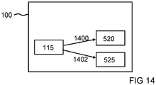
- FIG 14 shows a block diagram of an induction hob 100 of an embodiment.
- This can be an induction hob, as described with reference to the previous figures.
- the induction hob 100 comprises an operating unit 115 which enables a user to operate the induction hob 100. Using the operating unit 115, functions of the induction hob 100 can be activated and controlled.
- the operating unit 115 is designed to provide a motor control signal 1400 to an interface to the motor 520 of the drive unit or to a motor controller in response to a first input by the user.
- the motor control signal activates the motor 520 and / or sets a speed of the motor 520.
- the operating unit 115 is designed to send an induction control signal 1402 to an interface to the induction coil 525 or to an induction coil controller in response to a second input by the user provide.
- the induction control signal 1402 causes an activation of the induction coil 525 and / or a setting of a heating power of the induction coil 525.
- the pot module 400 is controlled with a display of the operating unit 115 that is already present on the induction hob 100.
- the control of the induction coil 525 is expanded to include the control of the motor 520.
- the hob and kitchen appliance are used separately, a user usually has to learn how to operate different devices / manufacturers. In addition, it is possibly not only the different operation, but also apps / clouds / guarantee / customer account etc. Such differences and the associated workload can be avoided by integrating the kitchen appliance into the induction hob 100 and, as described above, the operating unit 115 of the Induction hob 100 can be used to control the motor 520 for the pot module.
Abstract
Die Erfindung betrifft ein Induktionskochfeld mit einer Kochfeldplatte 105 mit einer Induktionsspule 525;1000 umfassenden Kochzone, wobei das Induktionskochfeld eine Aufnahmekammer 120 umfasst, die in der Kochzone angeordnet ist und eine Vertiefung zum Aufnehmen eines Topfmoduls ausformt, wobei das Topfmodul ein rotierbares Element mit einer Kupplungsschnittstelle zum Kuppeln des rotierbaren Elements mit einer Motorwelle 515 aufweist. Zudem umfasst das Induktionskochfeld eine Antriebseinrichtung 510, die an der Aufnahmekammer 120 angeordnet ist und einen die Motorwelle 515 aufweisenden Motor 520 umfasst.The invention relates to an induction hob with a hob plate 105 with a cooking zone comprising induction coil 525; 1000, the induction hob comprising a receiving chamber 120 which is arranged in the cooking zone and forms a recess for receiving a pot module, the pot module being a rotatable element with a coupling interface for coupling the rotatable element to a motor shaft 515. In addition, the induction hob comprises a drive device 510, which is arranged on the receiving chamber 120 and comprises a motor 520 having the motor shaft 515.
Description
Die Erfindung betrifft ein Induktionskochfeld mit einer Kochfeldplatte.The invention relates to an induction hob with a hob plate.
Das Marktvolumen von Küchenmaschinen, insbesondere Multifunktionsküchenmaschinen, hat in den letzten Jahren stark zugenommen. Multifunktionsküchenmaschinen sind in ihrer Form sehr voluminös und sperrig. Demgemäß muss die Küche genug Abstellflächen bieten, um einen Küchenhelfer auf der Arbeitsfläche oder im Küchenschrank zu verstauen. Insbesondere bei einer Nichtbenutzung oder eher seltenen Benutzung der Küchengeräte ist der Verlust der Arbeitsfläche oft ärgerlich. Multifunktionsküchenmaschinen verfügen häufig nicht über die Funktion des Bratens und sind somit oftmals nur in Abhängigkeit von weiteren Küchengeräten einsetzbar.The market volume for kitchen machines, especially multifunction kitchen machines, has increased significantly in recent years. Multifunction kitchen machines are very voluminous and bulky in shape. Accordingly, the kitchen must offer enough storage space to stow a kitchen helper on the work surface or in the kitchen cupboard. Losing the work surface is often annoying, especially when the kitchen appliances are not used or are used rarely. Multifunction kitchen machines often do not have the function of roasting and can therefore often only be used in conjunction with other kitchen appliances.
Der Erfindung stellt sich die Aufgabe ein verbessertes Induktionskochfeld mit einer Kochfeldplatte zu schaffen.The object of the invention is to create an improved induction hob with a hob plate.
Erfindungsgemäß wird diese Aufgabe durch ein Induktionskochfeld mit einer Kochfeldplatte mit den Merkmalen der Hauptansprüche gelöst. Vorteilhafte Ausgestaltungen und Weiterbildungen der Erfindung ergeben sich aus den nachfolgenden Unteransprüchen.According to the invention, this object is achieved by an induction hob with a hob plate with the features of the main claims. Advantageous refinements and developments of the invention emerge from the following subclaims.
Die mit der Erfindung erreichbaren Vorteile bestehen darin, dass für eine Basiseinheit einer Multifunktionsküchenmaschine erforderliche Einheiten in ein Induktionskochfeld integriert werden können. Es lässt sich somit eine Küchenmaschine im Kochfeld realisieren. Dies führt neben einer Platzeinsparung in der Küche bei der Verwendung von Multifunktionsküchenmaschinen zu einer erweiterten Funktionalität eines Induktionsherds. Ein handelsübliches Induktionskochfeld kann dadurch um weitere nützliche Funktionen aufgewertet werden. Beispielsweise Mixen, Kochen mit Rührfunktion, Dampfgaren und gegebenenfalls einer Waage. Dem Nutzer stehen somit viele benötigte Funktionen an einem Arbeitsplatz zur VerfügungThe advantages that can be achieved with the invention are that the units required for a base unit of a multifunction kitchen machine can be integrated into an induction hob. A kitchen machine can thus be implemented in the hob. In addition to saving space in the kitchen when using multifunction kitchen machines, this leads to an extended functionality of an induction cooker. A standard induction hob can be upgraded with additional useful functions. For example, mixing, cooking with a stirring function, steaming and, if necessary, a scale. The user thus has many required functions available at one workstation
Es wird ein Induktionskochfeld mit einer Kochfeldplatte mit einer eine Induktionsspule umfassende Kochzone vorgestellt, wobei das Induktionskochfeld die folgenden Merkmale aufweist:
- eine Aufnahmekammer, die in der Kochzone angeordnet ist und eine Vertiefung zum Aufnehmen eines Topfmoduls ausformt, wobei das Topfmodul ein rotierbares Element mit einer Kupplungsschnittstelle zum Kuppeln des rotierbaren Elements mit einer Motorwelle aufweist; und
- eine Antriebseinrichtung, die an der Aufnahmekammer angeordnet ist und einen die Motorwelle aufweisenden Motor umfasst.
- a receiving chamber which is arranged in the cooking zone and forms a recess for receiving a pot module, the pot module having a rotatable element with a coupling interface for coupling the rotatable element to a motor shaft; and
- a drive device which is arranged on the receiving chamber and comprises a motor having the motor shaft.
Das Induktionskochfeld kann auch als Herd bezeichnet werden. Die Kochfeldplatte kann beispielsweise als Glaskeramikplatte ausgeführt sein, unterhalb der eine oder mehrere Induktionsspulen angeordnet sein können. Wenn das Induktionskochfeld mehrere Kochzonen umfasst, kann jeder Kochzone zumindest eine Induktionsspule zugeordnet sein. Dabei kann eine der Kochzonen dergestalt erweitert sein, dass sich ein Ausschnitt mit einer Vertiefung in der Glasscheibe befindet, in der ein Topfmodul aufgenommen werden kann.The induction hob can also be called a stove. The hob plate can be designed, for example, as a glass ceramic plate, below which one or more induction coils can be arranged. If the induction hob comprises several cooking zones, at least one induction coil can be assigned to each cooking zone. One of the cooking zones can be expanded in such a way that there is a cutout with a recess in the glass pane, in which a pot module can be accommodated.
Bei dem Topfmodul kann es sich beispielsweise um den bei Multifunktionsküchenmaschinen verwendeten Mixtopf handeln, an dessen Boden ein rotierendes Element angeordnet sein kann. Das rotierende Element kann beispielsweise eine Rühreinheit oder rotierende Schneidemesser sein, mit denen im Topf befindliche Nahrungsmittel verrührt, gemischt, oder zerkleinert werden können. Durch die Antriebsvorrichtung kann das rotierende Element wie bei einer bekannten Multifunktionsküchenmaschine angetrieben werden. Dazu kann eine die Kupplungsschnittstelle umfassende Welle durch einen Boden des Topfmoduls geführt sein.The pot module can, for example, be the mixing pot used in multifunction kitchen machines, on the bottom of which a rotating element can be arranged. The rotating element can be, for example, a stirring unit or rotating cutting knife with which food in the pot can be stirred, mixed or chopped up. The rotating element can be driven by the drive device as in a known multifunction kitchen machine. For this purpose, a shaft encompassing the coupling interface can be passed through a base of the pot module.
Durch die Aufnahme des Topfmoduls in das Induktionskochfeld und durch den Antrieb des rotierenden Elements, beispielsweise der Schneidemesser, durch die in dem Induktionskochfeld integrierte Antriebseinrichtung, kann auf den großformatigen Unterbau bekannter Multifunktionsküchenmaschinen verzichtet werden. Somit kann die Basisaufnahme des beispielsweise als Mixtopf ausgeführten Topfmoduls optisch komplett im Kochfeld verschwinden, wodurch die Basisaufnahme vorteilhafterweise keine zusätzliche Arbeitsfläche in der Küche einnimmt. Des Weiteren kann das Topfmodul direkt unter einer über dem Herd angebrachten Dunstabzugshaube angeordnet werden, die beispielsweise bei der Funktion Dampfgaren direkt mit eingeschaltet werden kann.By accommodating the pot module in the induction hob and by driving the rotating element, for example the cutting knife, through the drive device integrated in the induction hob, the large-format substructure of known multifunction kitchen machines can be dispensed with. Thus, the base mount of the pot module, designed as a mixing bowl, for example, can optically disappear completely in the hob, so that the base mount advantageously does not take up any additional work surface in the kitchen. Furthermore, the pot module can be arranged directly under an extractor hood attached above the stove, which can be switched on directly with the steam cooking function, for example.
Bei der Integration einer Küchenmaschine in ein Induktionskochfeld mit Display liegt der Gewinn ferner in der Ausbeute von Synergieeffekten, zum Beispiel eine gemeinsame Bedienung über ein Display, Nutzung der vorhandenen Induktionstechnik zur Erwärmung oder der Verwendung von nur einem WLAN-Modul.When integrating a food processor into an induction hob with display, the benefit lies in the yield of synergy effects, for example joint operation via a display, use of the existing induction technology for heating or the use of only one WLAN module.
Gemäß einer Ausführungsform kann ein freies Ende der Motorwelle eine Gegenkupplungsstelle zum lösbaren Kuppeln der Motorwelle mit dem rotierbaren Element aufweisen. Die Kupplungsstellen können beispielsweise Zähne aufweisen, die bei einem Zusammenfügen der Kupplungsstellen ineinandergreifen können, um die Kupplung bereitzustellen. Vorteilhafterweise ermöglichen die Kupplungsstellen ein einfaches Einsetzen des Topfmoduls in die Aufnahmekammer.According to one embodiment, a free end of the motor shaft can have a counter-coupling point for releasably coupling the motor shaft to the rotatable element. The coupling points can, for example, have teeth which, when the coupling points are joined together, can mesh with one another in order to provide the coupling. The coupling points advantageously enable the pot module to be easily inserted into the receiving chamber.
Wird also beispielsweise ein Mixtopf einer Multifunktionsküchenmaschine in die Aufnahmekammer eingesetzt, dann kann die Motorwelle über die lösbare Kupplung mit dem rotierenden Element innerhalb des Mixtopfes verbunden werden. Eine rotierende Bewegung der Motorwelle kann dadurch beispielsweise Schneidemesser im Mixtopf antreiben. Eine solche Kupplung kann leicht lösbar ausgebildet sein um dem Nutzer das Einsetzen und Herausnehmen des Topfelementes zu erleichtern.If, for example, a mixing bowl of a multifunction kitchen machine is inserted into the receiving chamber, then the motor shaft can be connected to the rotating element inside the mixing bowl via the detachable coupling. A rotating movement of the motor shaft can, for example, drive cutting blades in the mixing bowl. Such a coupling can be designed to be easily detachable in order to make it easier for the user to insert and remove the pot element.
Gemäß einer weiteren Ausführungsform kann die Aufnahmekammer eine Bodenplatte zum Aufstellen des Topfmoduls und eine Dichtung umfassen. Dabei kann die Bodenplatte eine Öffnung für die Motorwelle aufweisen. Die Dichtung kann die Motorwelle gegenüber der Bodenplatte abdichten. Die Bodenplatte kann beispielsweise von der gleichen Ausführungsform sein wie die Kochfeldplatte um eine einheitliche Optik herzustellen. Die Öffnung in der Bodenplatte kann die Kupplung der Motorwelle mit dem rotierenden Element ermöglichen. Vorteilhafterweise kann eine solche Öffnung mit der Dichtung ausgebildet sein um das Eindringen von Flüssigkeiten zu verhindern, wie sie während des Kochvorgangs, zum Beispiel durch überkochendes Wasser, entstehen können. So kann vermieden werden, dass beispielsweise der Motor oder andere an der Kochzone angeordnete elektrische oder mechanische Elemente beschädigt werden können.According to a further embodiment, the receiving chamber can comprise a base plate for setting up the pot module and a seal. The base plate can have an opening for the motor shaft. The seal can seal the motor shaft against the base plate. The base plate can, for example, be of the same embodiment as the hob plate in order to produce a uniform appearance. The opening in the base plate can enable the coupling of the motor shaft with the rotating element. Such an opening can advantageously be formed with the seal in order to prevent the penetration of liquids such as can arise during the cooking process, for example through water boiling over. In this way it can be avoided that, for example, the motor or other electrical or mechanical elements arranged on the cooking zone can be damaged.
Gemäß einer weiteren Ausführungsform kann die Induktionsspule auf einer der Kochfeldplatte abgewandten Seite der Bodenplatte angeordnet sein. Will ein Nutzer beispielsweise die im Topfmodul verwendeten Nahrungsmittel erwärmen, braten oder garen, so kann er wie bei einem gewohnten Kochvorgang die Induktionsspule in Betrieb nehmen, wodurch das Topfmodul erwärmt werden kann. Das hat den Vorteil, dass das verwendete Topfmodul nicht nur als Mixtopf, sondern zugleich als Kochtopf genutzt werden kann und ein Synergieeffekt zwischen dem Induktionsherd und der Multifunktionsküchenmaschine erreicht werden kann.According to a further embodiment, the induction coil can be arranged on a side of the base plate facing away from the hob plate. If a user wants to heat, fry or cook the food used in the pot module, for example, he can operate the induction coil as in a normal cooking process, whereby the pot module can be heated. This has the advantage that the pot module used can not only be used as a mixing pot, but also as a cooking pot and a synergy effect can be achieved between the induction stove and the multifunction kitchen machine.
Gemäß einer weiteren Ausführungsform kann die Bodenplatte eine Mehrzahl von Vertiefungen, beispielsweise mindestens drei Vertiefungen zum Aufnehmen von Standeinheiten des Topfmoduls auf umfassen. Dabei können die Vertiefungen benachbart zu der Öffnung angeordnet sein. Solche Standeinheiten können beispielsweise wie kleine Füße ausgeformt sein, mit denen das Topfmodul zum Beispiel nach einem Kochvorgang auf einer Arbeitsfläche oder einem Tisch abgestellt werden kann. Beim Einsetzen des Topfmoduls in die Aufnahmekammer können die Füße am Außenradius der Bodenplatte eintauchen. Eine solche Ausführungsform hat den Vorteil stabilisierend auf das Topfmodul einzuwirken und beispielsweise ein Mitdrehen des Topfmoduls mit der Motorwelle zu vermeiden.According to a further embodiment, the base plate can comprise a plurality of depressions, for example at least three depressions for receiving standing units of the pot module. The depressions can be arranged adjacent to the opening. Such stand units can for example be shaped like small feet with which the pot module can be placed on a work surface or table, for example after a cooking process. When inserting the pot module into the receiving chamber, the feet can dip into the outer radius of the base plate. Such an embodiment has the advantage of having a stabilizing effect on the pot module and, for example, of preventing the pot module from rotating with the motor shaft.
Gemäß einer weiteren Ausführungsform kann die Aufnahmekammer durch einen Deckel verschließbar ausgeformt sein. Vorteilhafterweise kann die Aufnahmekammer so jederzeit verschlossen werden, wenn sich kein Topfmodul darin befindet.According to a further embodiment, the receiving chamber can be designed such that it can be closed by a cover. The receiving chamber can thus advantageously be closed at any time if there is no pot module in it.
Gemäß einer weiteren Ausführungsform ist der Deckel ausgeformt um ebenflächig mit der Kochfeldplatte des Induktionskochfelds abzuschließen. Dies erleichtert es beispielsweise einen Topf auf den Deckel zu verschieben.According to a further embodiment, the cover is shaped so as to be flush with the hob plate of the induction hob. This makes it easier to move a saucepan onto the lid, for example.
Es kann empfehlenswert sein für den Deckel das gleiche Material zu wählen aus dem auch die Kochfeldplatte besteht, beispielsweise Glaskeramik. Ferner kann der Deckel so ausgeformt werden, dass er beim Einsetzen in die Kochfeldplatte lückenlos mit dieser verschlossen werden kann. Eine solche Ausführungsform hat den Vorteil, dass sich die Aufnahmekammer und der Deckel einerseits optisch in das Design der Kochfeldplatte einfügen und andererseits auf dem Deckel Gegenstände abgestellt werden können, solange die Aufnahmekammer nicht für ein Topfmodul verwendet wird.It may be advisable to choose the same material for the cover as the hob plate is made of, for example glass ceramic. Furthermore, the cover can be shaped in such a way that it can be closed with the hob plate without any gaps when it is inserted. Such an embodiment has the advantage that, on the one hand, the receiving chamber and the lid fit optically into the design of the hob plate and, on the other hand, objects can be placed on the lid as long as the receiving chamber is not used for a pot module.
Gemäß einer weiteren Ausführungsform ist die Induktionsspule zum Erhitzen eines auf den Deckel abgestellten Kochgeschirrs verwendbar. Will ein Nutzer beispielsweise während eines Kochvorgangs die Kochzone, in der die Aufnahmekammer angeordnet ist, nicht für eine Multifunktionsküchenmaschine nutzen, dann kann sie im verschlossenen Zustand wie die anderen Kochzonen des Induktionskochfelds genutzt werden. Beispielsweise können darauf abgestellte Töpfe oder Pfannen erhitzt werden. Das hat den Vorteil, dass das Induktionskochfeld trotz der zusätzlichen Integration einer Multifunktionsküchenmaschine noch im gleichen Umfang für normale Kochvorgänge genutzt werden kann wie es ohne eine solche Integration möglich wäre.According to a further embodiment, the induction coil can be used for heating cookware placed on the lid. For example, if a user does not want to use the cooking zone in which the receiving chamber is arranged for a multifunction kitchen machine during a cooking process, then it can be used in the locked state like the other cooking zones of the induction hob. For example, pots or pans placed on it can be heated. This has the advantage that, despite the additional integration of a multifunction kitchen appliance, the induction hob can still be used to the same extent for normal cooking processes as would be possible without such an integration.
Gemäß einer weiteren Ausführungsform kann das Induktionskochfeld eine weitere eine Induktionsspule umfassende Kochzone umfassen. Dabei kann die Kochfeldplatte im Bereich der weiteren Kochzone durchgängig ausgeformt sein. Beispielsweise kann das Induktionskochfeld drei Kochzonen aufweisen, an denen keine Aufnahmekammern angeordnet sind und die somit von einem Nutzer für gewohnte Kochvorgänge verwendet werden können. Zusätzlich kann ein solches Induktionskochfeld eine Kochzone mit einer Aufnahmekammer entsprechend einer zuvor beschriebenen Ausführungsform umfassen. Eine solche Kombination ist besonders vorteilhaft, da in einer Küche meist nicht mehr als eine Multifunktionsküchenmaschine benötigt wird und ein Induktionskochfeld so mit möglichst geringem Kosten- und Arbeitsaufwand um ein solches Gerät erweitert werden kann.According to a further embodiment, the induction hob can comprise a further cooking zone comprising an induction coil. The hob plate can be continuously shaped in the area of the further cooking zone. For example, the induction hob can have three cooking zones on which no receiving chambers are arranged and which can thus be used by a user for usual cooking processes. In addition, such an induction hob can comprise a cooking zone with a receiving chamber in accordance with an embodiment described above. Such a combination is particularly advantageous since in a kitchen mostly no more than one multifunction kitchen machine is required and an induction hob can be expanded with such a device with the least possible cost and effort.
Gemäß einer weiteren Ausführungsform kann das Induktionskochfeld eine Bedieneinheit umfassen, die ausgebildet ist um ansprechend auf eine Benutzereingabe ein Steuersignal zum Ansteuern des Motors und zusätzlich oder alternativ der Induktionsspule bereitzustellen.According to a further embodiment, the induction hob can comprise an operating unit which is designed to provide a control signal for controlling the motor and additionally or alternatively the induction coil in response to a user input.
Beispielsweise verfügen die meisten Induktionskochfelder über eine Bedieneinheit mit Display über das ein Nutzer die Funktionen des Induktionskochfeldes ansteuern kann. Eine solche Bedieneinheit kann um die Funktion des Ansteuerns des Motors erweitert werden, sodass ein Nutzer über das bereits vorhandene Display im Induktionskochfeld auch die Multifunktionsküchenmaschine bedienen kann. Das hat den Vorteil, dass auf eine zusätzliche Bedieneinheit an der Multifunktionsküchenmaschine verzichtet werden kann und das Induktionskochfeld mit einer integrierten Multifunktionsküchenmaschine besonders benutzerfreundlich aufgebaut werden kann.For example, most induction hobs have an operating unit with a display which a user can use to control the functions of the induction hob. Such an operating unit can be expanded to include the function of controlling the motor, so that a user can also operate the multifunction kitchen machine using the display in the induction hob. This has the advantage that there is no need for an additional control unit on the multifunction kitchen machine and the induction hob with an integrated multifunction kitchen machine can be set up in a particularly user-friendly manner.
Auch wenn der beschriebene Ansatz anhand eines Haushaltgeräts beschrieben wird, kann die hier beschrieben Vorrichtung entsprechend im Zusammenhang mit einem gewerblichen oder professionellen Gerät eingesetzt werden.Even if the approach described is described using a household appliance, the device described here can be used accordingly in connection with a commercial or professional appliance.
Ein Ausführungsbeispiel der Erfindung ist in den Zeichnungen rein schematisch dargestellt und wird nachfolgend näher beschrieben. Es zeigt
- Figur 1
- eine Draufsicht eines Ausführungsbeispiels eines Induktionskochfelds;
Figur 2- eine Draufsicht eines Ausführungsbeispiels eines Induktionskochfelds mit einer Aufnahmekammer;
Figur 3- eine Draufsicht eines Ausführungsbeispiels eines Induktionskochfelds mit einer Aufnahmekammer und einem Deckel;
- Figur 4
- eine Draufsicht eines Ausführungsbeispiels eines Induktionskochfelds mit einem Topfmodul;
- Figur 5
- einen Querschnitt eines Ausführungsbeispiels einer Aufnahmekammer;
- Figur 6a
- eine Draufsicht eines Ausführungsbeispiels einer Bodenplatte;
- Figur 6b
- eine Draufsicht eines Ausführungsbeispiels einer Bodenplatte;
- Figur 7a
- einen Querschnitt eines Ausführungsbeispiels eines mit dem Motor gekuppelten Topfmoduls;
- Figur 7b
- einen Querschnitt eines Ausführungsbeispiels eines mit dem Motor gekuppelten Topfmoduls;
- Figur 7c
- einen Querschnitt eines Ausführungsbeispiels eines über eine Motorwelle mit einem Motor gekoppelten rotierbaren Elements;
- Figur 8
- einen Querschnitt eines Ausführungsbeispiels einer Aufnahmekammer mit eingesetztem Topfmodul;
- Figur 9
- eine Draufsicht eines Ausführungsbeispiels einer Bodenplatte mit darunter angeordneter Induktionsspule;
- Figur 10
- einen Querschnitt einer Aufnahmekammer mit eingesetztem Topfmodul gemäß einem Ausführungsbeispiel;
- Figur 11
- eine Draufsicht auf eine Bodenplatte mit darunter angeordneter Induktionsspule gemäß einem Ausführungsbeispiel;
- Figur 12
- einen Querschnitt einer Aufnahmekammer mit eingesetztem Topfmodul gemäß einem Ausführungsbeispiel;
- Figur 13
- eine Draufsicht auf eine Bodenplatte mit darunter angeordneter Induktionsspule gemäß einem Ausführungsbeispiel; und
- Figur 14
- ein Blockschaltbild eines Ausführungsbeispiels eines Induktionskochfelds mit einer Bedieneinheit und einem Steuersignal zum Ansteuern des Motors und/oder der Induktionsspule.
- Figure 1
- a plan view of an embodiment of an induction hob;
- Figure 2
- a plan view of an embodiment of an induction hob with a receiving chamber;
- Figure 3
- a plan view of an embodiment of an induction hob with a receiving chamber and a lid;
- Figure 4
- a plan view of an embodiment of an induction hob with a pot module;
- Figure 5
- a cross section of an embodiment of a receiving chamber;
- Figure 6a
- a top view of an embodiment of a base plate;
- Figure 6b
- a top view of an embodiment of a base plate;
- Figure 7a
- a cross section of an embodiment of a pot module coupled to the motor;
- Figure 7b
- a cross section of an embodiment of a pot module coupled to the motor;
- Figure 7c
- a cross section of an embodiment of a rotatable element coupled to a motor via a motor shaft;
- Figure 8
- a cross section of an embodiment of a receiving chamber with an inserted pot module;
- Figure 9
- a plan view of an embodiment of a base plate with an induction coil arranged below;
- Figure 10
- a cross section of a receiving chamber with inserted pot module according to an embodiment;
- Figure 11
- a plan view of a base plate with an induction coil arranged underneath according to an exemplary embodiment;
- Figure 12
- a cross section of a receiving chamber with inserted pot module according to an embodiment;
- Figure 13
- a plan view of a base plate with an induction coil arranged underneath according to an exemplary embodiment; and
- Figure 14
- a block diagram of an embodiment of an induction hob with an operating unit and a control signal for controlling the motor and / or the induction coil.
Es ist anzumerken, dass herkömmliche Küchenmaschinen, insbesondere durch die Kombination beispielsweise eines Mixtopfes mit einem oft relativ voluminösen Unterbau, nicht nur viel Platz von der Arbeitsfläche in der Küche einnehmen, sondern auch in den Küchenschränken, wenn man die Maschine überhaupt verstauen kann. Des Weiteren müssen oft für unterschiedliche Anwendungen verschiedene Küchengeräte gekauft werden, was gegebenenfalls das Platzproblem verstärkt oder für den Nutzer kostspielig werden kann. Des Weiteren steht die Bedienungsfreundlichkeit für den Kunden im Fokus. Als technische Lösung bietet sich ein Kombinationsgerät an, welches das Induktionskochfeld 100 mit einer integrierten Küchenmaschine umfasst. Bei einer Integration des Topfmoduls 400 der Küchenmaschine in das Induktionskochfeld 100, wie es aus den
In der Mitte der Bodenplatte 500 befindet sich eine Öffnung 505 für eine Antriebseinrichtung 510, die eine Motorwelle 515 und einen Motor 520 umfasst. In diesem Ausführungsbeispiel wurde als Form der Öffnung 505 eine Sternenform gewählt. Der Motor 520, beispielsweise ein Elektromotor, ist auf einer der Kochfeldplatte 105 abgewandten Seite der Bodenplatte 500 angeordnet. Die Motorwelle 515 ist zentral durch die Öffnung 505 durchgeführt und an einer Seite direkt mit dem Motor 520 verbunden. Wird nun beispielsweise ein Topfmodul in die Aufnahmekammer 120 eingesetzt, so kann es über die Motorwelle 515 mit dem Motor 520 gekoppelt werden.In the middle of the
In diesem Ausführungsbeispiel ist direkt unterhalb der Bodenplatte 500 eine Induktionsspule 525 angeordnet. Unter Verwendung der Induktionsspule 525 kann ein Topfmodul erwärmt werden um beispielsweise darin befindliche Nahrungsmittel zu kochen, zu braten oder zu garen.In this exemplary embodiment, an
Eine Form der Bodenplatte 500 kann an eine Form eines Bodens des Topfmoduls angepasst sein. Beispielhaft ist die Bodenplatte 500 kreisförmig. Ein Spalt zwischen der Kochfeldplatte 105 und der Bodenplatte 500 ist gemäß diesem Ausführungsbeispiel durch eine umlaufende Wand 530 verdeckt. Beispielsweise liegt eine Höhe der Wand 530 zwischen einem Fünftel und einer Hälfte des Durchmessers der Bodenplatte 500.A shape of the
Zusätzlich zu der Öffnung 505 sind auch in diesem Ausführungsbeispiel drei Vertiefungen 605 zur Aufnahme von Standeinheiten eines Topfmoduls abgebildet.In addition to the
Das Topfmodul 400 umfasst in diesem Ausführungsbeispiel ein zentral angeordnetes rotierbares Element 700, das in diesem Ausführungsbeispiel ein an einer Topfwelle befestigtes Schneidmesser aufweist, mit denen zum Beispiel in das Topfmodul 400 gegebene Nahrungsmittel zerkleinert werden können. Die Topfwelle ist in einem Lager 705 in einem Topfboden 710 des Topfmoduls 400 drehbar gelagert. Ein freies Ende der Topfwelle ist mit einem freien Ende der Motorwelle 515 gekuppelt. Die Motorwelle 515 stellt somit den Kontakt vom Motor 520 zum Topfmodul 400 her und kann die Messer des rotierbaren Element 700 im Topfinneren des Topfmoduls 400 antreiben. Die Kraftübertragung zwischen der Motorwelle 515 und der Topfwelle erfolgt über eine lösbare Kupplung 715. Zum Ausformen der Kupplung 715 weist das rotierbare Element 700 an der Topfwelle eine Kupplungsschnittstelle auf, die ausgeformt ist in eine Gegenkupplungsstelle der Motorwelle 515 einzugreifen. Durch die Kupplung 715 wird eine Rotation der Motorwelle 515 auf das Schneidmesser im Inneren des Topfmoduls 400 übertragen. Gemäß diesem Ausführungsbeispiel ist die Kupplung 715 Teil eines Mitnahmebauteils, das in einer Ausnehmung des Topfbodens 710 realisiert ist. Die Motorwelle 515 ragt im gekuppelten Zustand in die Ausnehmung des Topfbodens 710 hinein.In this exemplary embodiment, the
Beispielsweise kann ein Nutzer verschiedene Nahrungsmittel, die für den Kochvorgang zerkleinert werden sollen, in das Topfmodul 400 geben und dann den Motor 520 einschalten um das Schneidmesser in Gang zu setzen. Auf diese Art lassen sich auch ähnliche Vorgänge umsetzen, wie beispielsweise das Verrühren von Saucen, wenn das rotierbare Element 700 beispielsweise als Rührgerät ausgeführt ist.For example, a user can put various foods to be chopped up for the cooking process into the
Will der Nutzer das Topfmodul 400 entfernen, so kann er die Kupplung 715 leicht lösen und das Topfmodul 400 aus der Aufnahmekammer 120 entfernen und es nach Belieben auf beispielsweise einem Tisch oder einer anderen Arbeitsfläche abstellen, wobei das Topfmodul 400 auf Standeinheiten 720 des Bodens 710 zum Stehen kommt. Beispielhaft sind in
Zusammen mit der Antriebseinrichtung stellt das Topfmodul 400 gemäß einem Ausführungsbeispiel die Funktionalität einer bekannten Küchenmaschine bereit.Together with the drive device, the
Durch eine solche Anordnung ist es beispielsweise möglich Nahrungsmittel, die in das Topfmodul 400 gegeben werden, nicht nur mittels des rotierbaren Elements zu verrühren, sondern zugleich durch Einsatz der Induktionsspule 525 zu erwärmen. Zum Beispiel wäre es einem Nutzer durch diese Konstruktion möglich, eine Sauce auf einer voreingestellten Temperatur köcheln und zugleich gleichmäßig verrühren zu lassen.Such an arrangement makes it possible, for example, not only to stir food that is placed in the
Beispielhaft ist die Bedieneinheit 115 ausgebildet um ansprechend auf eine erste Eingabe des Nutzers ein Motorsteuersignal 1400 an eine Schnittstelle zu dem Motor 520 der Antriebseinheit oder zu einer Motorsteuerung bereitzustellen. Das Motorsteuersignal bewirkt dabei eine Aktivierung des Motors 520 und/oder eine Einstellung einer Drehzahl des Motors 520. Zusätzlich oder alternativ ist die Bedieneinheit 115 ausgebildet um ansprechend auf eine zweite Eingabe des Nutzers ein Induktionssteuersignal 1402 an eine Schnittstelle zu der Induktionsspule 525 oder zu einer Induktionsspulensteuerung bereitzustellen. Das Induktionssteuersignal 1402 bewirkt dabei eine Aktivierung der Induktionsspule 525 und/oder eine Einstellung einer Heizleistung der Induktionsspule 525.By way of example, the
Gemäß einem Ausführungsbeispiel wird mit einem am Induktionskochfeld 100 bereits vorhandenen Display der Bedieneinheit 115 das Topfmodul 400 angesteuert. Dabei wird das Ansteuern der Induktionsspule 525 um die Motoransteuerung des Motors 520 erweitert.According to one exemplary embodiment, the
Bei einer getrennten Verwendung von Kochfeld und Küchenmaschine muss ein Nutzer sich üblicherweise die Bedienung von verschiedenen Geräten/Herstellern aneignen. Darüber hinaus ist es gegebenenfalls nicht nur die unterschiedliche Bedienung, sondern auch Apps/Clouds/Garantie/Kundenkonto etc. Solche Unterschiede und der damit verbundene Arbeitsaufwand können vermieden werden, indem die Küchenmaschine ihn das Induktionskochfeld 100 integriert wird und wie zuvor beschrieben die Bedieneinheit 115 des Induktionskochfelds 100 zum Ansteuern des Motors 520 für das Topfmodulverwendet werden kann.If the hob and kitchen appliance are used separately, a user usually has to learn how to operate different devices / manufacturers. In addition, it is possibly not only the different operation, but also apps / clouds / guarantee / customer account etc. Such differences and the associated workload can be avoided by integrating the kitchen appliance into the
Claims (10)
Applications Claiming Priority (1)
| Application Number | Priority Date | Filing Date | Title |
|---|---|---|---|
| DE102020112626.3A DE102020112626A1 (en) | 2020-05-11 | 2020-05-11 | Induction hob with a hob plate |
Publications (1)
| Publication Number | Publication Date |
|---|---|
| EP3911118A1 true EP3911118A1 (en) | 2021-11-17 |
Family
ID=75625361
Family Applications (1)
| Application Number | Title | Priority Date | Filing Date |
|---|---|---|---|
| EP21169431.0A Withdrawn EP3911118A1 (en) | 2020-05-11 | 2021-04-20 | Induction hob with a hotplate field |
Country Status (2)
| Country | Link |
|---|---|
| EP (1) | EP3911118A1 (en) |
| DE (1) | DE102020112626A1 (en) |
Citations (3)
| Publication number | Priority date | Publication date | Assignee | Title |
|---|---|---|---|---|
| US20080264927A1 (en) * | 2007-04-27 | 2008-10-30 | Zheng Peng | Cooking range having a motorized stove base |
| JP2011258442A (en) * | 2010-06-10 | 2011-12-22 | Toshiba Corp | Induction heating cooker |
| WO2014033652A1 (en) * | 2012-08-29 | 2014-03-06 | Koninklijke Philips N.V. | Cooking stove having a drive assembly for driving a food processing assembly in a pan |
-
2020
- 2020-05-11 DE DE102020112626.3A patent/DE102020112626A1/en active Pending
-
2021
- 2021-04-20 EP EP21169431.0A patent/EP3911118A1/en not_active Withdrawn
Patent Citations (3)
| Publication number | Priority date | Publication date | Assignee | Title |
|---|---|---|---|---|
| US20080264927A1 (en) * | 2007-04-27 | 2008-10-30 | Zheng Peng | Cooking range having a motorized stove base |
| JP2011258442A (en) * | 2010-06-10 | 2011-12-22 | Toshiba Corp | Induction heating cooker |
| WO2014033652A1 (en) * | 2012-08-29 | 2014-03-06 | Koninklijke Philips N.V. | Cooking stove having a drive assembly for driving a food processing assembly in a pan |
Also Published As
| Publication number | Publication date |
|---|---|
| DE102020112626A1 (en) | 2021-11-11 |
Similar Documents
| Publication | Publication Date | Title |
|---|---|---|
| DE3228220C2 (en) | Combination microwave oven with a gas sensor | |
| EP2460452A1 (en) | Kitchen appliance with a mixing container | |
| EP2688364B1 (en) | Hotplate device | |
| DE102017101168A1 (en) | Hob with integrated accessories for the preparation of food | |
| DE19624648A1 (en) | Special cooking pot for cooking plate-simmering unit | |
| EP1010949B1 (en) | Device combination, comprising a cooking apparatus and a vapour-exhaust extraction system | |
| EP3936014B1 (en) | Food preparation device for cutting food, crushing attachment and method | |
| EP3911118A1 (en) | Induction hob with a hotplate field | |
| DE102020110966B4 (en) | Hob and food preparation vessel and this comprehensive preparation device | |
| EP4101349B1 (en) | Method for potato peeling and kitchen appliance | |
| EP3710752B1 (en) | Food preparation system | |
| WO2020128014A1 (en) | Induction energy transmission system | |
| EP0813031B1 (en) | Cooking plate with electrical connector | |
| EP3561390A1 (en) | Domestic appliance | |
| DE102015110650A1 (en) | Cooking system and method of operation | |
| AT503495A1 (en) | DEVICE FOR PREPARING BEVERAGES | |
| DE102016115240B4 (en) | Cooking device for cooking and cooking unit with one cooking device | |
| AT391610B (en) | Cooking device | |
| EP2635848B1 (en) | Cooktop arrangement | |
| DE102007040649A1 (en) | Product and language-independent, graphical display and operating device of a cooking appliance and cooking appliance therefor | |
| WO2021083740A1 (en) | Food preparation system | |
| EP3636118B1 (en) | Kitchen appliance with adaptive adjustment of an operating parameter | |
| DE10327912B4 (en) | Multifunctional workplace, especially kitchen workplace | |
| DE102020112609A1 (en) | Stabilization unit for a multifunctional kitchen machine that is or can be integrated into a worktop | |
| DE202022102402U1 (en) | Food processor and extension device therefor |
Legal Events
| Date | Code | Title | Description |
|---|---|---|---|
| PUAI | Public reference made under article 153(3) epc to a published international application that has entered the european phase |
Free format text: ORIGINAL CODE: 0009012 |
|
| STAA | Information on the status of an ep patent application or granted ep patent |
Free format text: STATUS: THE APPLICATION HAS BEEN PUBLISHED |
|
| AK | Designated contracting states |
Kind code of ref document: A1 Designated state(s): AL AT BE BG CH CY CZ DE DK EE ES FI FR GB GR HR HU IE IS IT LI LT LU LV MC MK MT NL NO PL PT RO RS SE SI SK SM TR |
|
| B565 | Issuance of search results under rule 164(2) epc |
Effective date: 20211004 |
|
| STAA | Information on the status of an ep patent application or granted ep patent |
Free format text: STATUS: THE APPLICATION IS DEEMED TO BE WITHDRAWN |
|
| 18D | Application deemed to be withdrawn |
Effective date: 20220518 |