EP3910161A1 - Bohrgestängekupplung - Google Patents
Bohrgestängekupplung Download PDFInfo
- Publication number
- EP3910161A1 EP3910161A1 EP20174448.9A EP20174448A EP3910161A1 EP 3910161 A1 EP3910161 A1 EP 3910161A1 EP 20174448 A EP20174448 A EP 20174448A EP 3910161 A1 EP3910161 A1 EP 3910161A1
- Authority
- EP
- European Patent Office
- Prior art keywords
- coupling
- locking
- receptacle
- drill
- drill rod
- Prior art date
- Legal status (The legal status is an assumption and is not a legal conclusion. Google has not performed a legal analysis and makes no representation as to the accuracy of the status listed.)
- Granted
Links
Images

Classifications
-
- E—FIXED CONSTRUCTIONS
- E21—EARTH OR ROCK DRILLING; MINING
- E21B—EARTH OR ROCK DRILLING; OBTAINING OIL, GAS, WATER, SOLUBLE OR MELTABLE MATERIALS OR A SLURRY OF MINERALS FROM WELLS
- E21B17/00—Drilling rods or pipes; Flexible drill strings; Kellies; Drill collars; Sucker rods; Cables; Casings; Tubings
- E21B17/02—Couplings; joints
- E21B17/03—Couplings; joints between drilling rod or pipe and drill motor or surface drive, e.g. between drilling rod and hammer
-
- E—FIXED CONSTRUCTIONS
- E21—EARTH OR ROCK DRILLING; MINING
- E21B—EARTH OR ROCK DRILLING; OBTAINING OIL, GAS, WATER, SOLUBLE OR MELTABLE MATERIALS OR A SLURRY OF MINERALS FROM WELLS
- E21B17/00—Drilling rods or pipes; Flexible drill strings; Kellies; Drill collars; Sucker rods; Cables; Casings; Tubings
- E21B17/02—Couplings; joints
- E21B17/04—Couplings; joints between rod or the like and bit or between rod and rod or the like
- E21B17/046—Couplings; joints between rod or the like and bit or between rod and rod or the like with ribs, pins, or jaws, and complementary grooves or the like, e.g. bayonet catches
-
- E—FIXED CONSTRUCTIONS
- E21—EARTH OR ROCK DRILLING; MINING
- E21B—EARTH OR ROCK DRILLING; OBTAINING OIL, GAS, WATER, SOLUBLE OR MELTABLE MATERIALS OR A SLURRY OF MINERALS FROM WELLS
- E21B17/00—Drilling rods or pipes; Flexible drill strings; Kellies; Drill collars; Sucker rods; Cables; Casings; Tubings
- E21B17/02—Couplings; joints
- E21B17/04—Couplings; joints between rod or the like and bit or between rod and rod or the like
- E21B17/046—Couplings; joints between rod or the like and bit or between rod and rod or the like with ribs, pins, or jaws, and complementary grooves or the like, e.g. bayonet catches
- E21B17/0465—Couplings; joints between rod or the like and bit or between rod and rod or the like with ribs, pins, or jaws, and complementary grooves or the like, e.g. bayonet catches characterised by radially inserted locking elements
Definitions
- the invention relates to a drill pipe coupling with a sleeve-shaped coupling receptacle, a pin-shaped coupling member which can be axially inserted into the coupling receptacle to form a non-rotatable connection, and at least one locking bolt which is directed transversely to the axial coupling direction and is in a locked coupling position from the coupling receptacle in a locking recess extends on the coupling member according to the preamble of claim 1.
- Such a drill pipe coupling is for example from DE 10 2011 109 001 A1 known.
- This drill pipe coupling is often referred to as a so-called Kelly box.
- an axial locking is effected in that a transversely directed locking bolt is inserted into the coupling receptacle and the coupling member, so that a form-fitting connection is achieved.
- the known drill pipe coupling requires manual activities by operating personnel both when locking and when unlocking. These are generally time-consuming.
- the coupling arrangements can be located several meters above the ground. For actuation, therefore, climbing aids or even lifting vehicles are required, which is also complex.
- work at greater heights above the ground and also in the immediate area of action of a drill rod for reasons of Occupational safety is problematic and should therefore be reduced to a necessary minimum.
- the invention is based on the object of specifying a drill pipe coupling which can be actuated particularly easily.
- the drill pipe coupling according to the invention is characterized in that the locking bolt is mounted radially adjustable between an unlocking position and a locking position by means of a gravity-dependent adjustment mechanism on the sleeve-shaped coupling receptacle Locking position is pushed, and an upper retracted position is movable, in which the locking bolt is withdrawn from the locking receptacle into the unlocking position, and that the actuator is held by gravity in the lower insertion position.
- a basic idea of the invention can be seen in providing an at least semi-automatic drill rod coupling in which the locking bolt on the outer coupling receptacle can be adjusted between an unlocking position and a locking position by a gravity-dependent adjustment mechanism.
- the adjustment mechanism has at least one movable actuator which is pulled down by gravity, the locking bolt being pushed into an insertion position and held therein by the adjustment mechanism.
- a drill rod with the coupling receptacle or the coupling member can be coupled axially in a simple manner to an associated coupling member or a coupling receptacle of another drill rod element, whereby the locking bolt with the actuator is briefly displaced against the force of gravity by the axial insertion force until the locking bolt is displaced by the The gravity-dependent adjustment mechanism is pushed back into the locking position in order to lock the two drill rod elements.
- the coupling member and the locking bolt can be beveled at their free end for this purpose.
- a desired actuating force on the at least one actuator can be achieved in that a load weight is arranged on the at least one actuator.
- the load weight can be releasably attached to the actuator.
- a desired actuating force can be specified by increasing or reducing the load weight accordingly.
- a particularly reliable connection is achieved in that several locking bolts are provided, which are arranged, preferably evenly, distributed over the circumference of the sleeve-shaped coupling receptacle.
- two to four locking bolts can be distributed around the circumference of the coupling receptacle.
- the locking recess can be designed as a blind hole or a through hole in the coupling member.
- the locking recess is designed as an annular groove which extends along the circumference of the pin-shaped coupling member.
- a cross-sectional contour of the groove corresponds to part of the outer circumferential contour of the locking bolt.
- the groove preferably has a semicircular cross-section.
- the movable actuator of the adjustment mechanism can be pushed upwards by hand or by a hand-operated tool, so that the locking bolt is withdrawn.
- an unlocking device is arranged on the adjusting mechanism, with which the at least one actuator can be moved into the upper retracted position.
- the unlocking device can be energized.
- an unlocking device can be provided, for example, on a drill drive, on which an energy supply is basically already provided.
- the unlocking device can be operated electrically, hydraulically or pneumatically.
- the unlocking device can be actuated with an actuating rod.
- the unlocking device can be a simple hook element or some other receptacle for such a mechanical actuation or a simple handle.
- the unlocking device has a ring member to which one or more actuators are articulated.
- the ring member can surround the coupling receptacle in a ring shape, so that the unlocking device can be actuated from any circumferential position, for example when actuated with an actuating rod.
- the coupling receptacle and the coupling member have a polygonal cross-sectional shape, in particular a square cross-section.
- a triangular or other polygonal cross section is also possible, which enables torque to be transmitted between the coupling receptacle and the coupling member.
- the corresponding plug-in areas of the coupling receptacle and coupling member are designed as a clearance fit.
- the invention further comprises a drill pipe arrangement with the drill pipe coupling described above. It is preferred that the drill pipe coupling is arranged between two drill pipe elements.
- the drill rod elements can be designed purely cylindrical on their outside with a conveying helix, stirring elements or without any elements.
- a drill pipe arrangement with such a drill pipe coupling is provided, the drill pipe coupling being provided between a drill pipe element and a drilling tool or a drill drive is.
- the pin-shaped coupling member is preferably arranged at the top, while the sleeve-shaped coupling receptacle is arranged at the bottom relative to the associated coupling member.
- a drilling tool a screw auger, a box drill, a displacement drill or some other drilling tool can be provided, which is driven in rotation.
- a further advantageous embodiment of the invention results from the fact that the coupling receptacle and / or the coupling member are detachably attached to a drill rod element, a drilling tool or a drill drive.
- the coupling receptacle and / or the coupling member can thus be designed as a type of adapter between the drill pipe coupling according to the invention and conventional coupling elements, such as a Kelly box or a Kelly plug-in member. This also enables existing elements to be easily retrofitted.
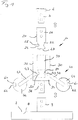
- a drill pipe coupling 10 according to the invention has a pin-shaped coupling member 20 which is attached to a drill pipe element 2 which is only partially shown.
- the coupling member 20 can in principle be permanently welded to the drill rod element 2 or even be formed in one piece thereon.
- a retrofitting option is shown, the drill rod element 2 having a connecting section 3.
- the connecting section 3 can be a conventional Kelly connection with a square area.
- the pin-shaped coupling member 20 has a cylindrical front section 22 and a sleeve-shaped rear section 26.
- the connecting section 3 of the drill rod element 2 can be inserted into the sleeve-shaped rear section 26 of the coupling member 20 in a suitable and rotationally fixed manner and axially fixed therein by transversely directed bolts.
- An annular groove 25 is made as a locking recess 24 along the outer circumference of the peg-shaped front section 22 of the coupling member 20.
- the groove 25 has an approximately semicircular shape in cross section.
- a tapering head 23 with a downwardly decreasing diameter is formed at the free end of the front section 22.
- the sleeve-shaped coupling receptacle 30 is attached to a drilling tool 7 in the embodiment shown.
- the drilling tool 7 has a schematically illustrated base body 8, on the upper side of which a sleeve-shaped connecting area 9 is attached centrally to a longitudinal axis.
- the drilling tool 7 can, for example, be a drilling bucket with a corresponding removal device for removing soil material.
- the sleeve-shaped coupling receptacle 30 can also be fixedly attached to the drilling tool 7, for example by welding.
- the coupling receptacle 30 has a circumferential sleeve 32 with a central stepped receiving hole 33, which preferably has a square cross-section corresponding to an outer contour of the pin-shaped coupling member 20.
- An underside of the circumferential sleeve 32 is closed with a plate-shaped base 34, on the underside of which a pin-shaped connecting element 36 protrudes downward.
- the connecting element 36 is preferably designed in the same way as the connecting section 3 on the drill rod element 2, so that the coupling receptacle 30 can also be used in a simple manner as a retrofit part for existing Kelly connections.
- the peg-shaped connecting element 36 which is preferably designed as a square, can be inserted axially into the sleeve-shaped connecting area 9 on the drilling tool 7 in a suitable manner. It can be axially fixed therein by means of corresponding transversely directed bolts, so that a non-rotatable and axially secured connection is formed between the drilling tool 7 and the coupling receptacle 30.
- An adjusting mechanism 40 is arranged on the coupling receptacle 30, which in the illustrated embodiment has two lever-like actuators 42, which are each pivotably mounted via a pivot axis 43 on a passage on the circumferential sleeve 32 of the coupling receptacle 30.
- a locking bolt 50 is formed in one piece with the lever-shaped actuator 42 at a free end protruding inwardly into the receiving hole 33. Via a load weight 44 at the outer end of each actuator 42, this is pressed down into an insertion position in which the locking bolt 50 is pressed or pushed radially inwards into the receiving hole 33 into a locking position.
- a recess 62 of an unlocking device 60 is formed on each of the load weights 44.
- An actuating rod can be inserted into the recess 62, with which the load weight 44 and thus the actuator 42 can be moved upward into a retracted position.
- the locking bolt 50 is pushed radially outward into an unlocking position in which the locking bolt 50 no longer engages in a locking recess 24 of an axially inserted coupling member 20. In this unlocking position, a coupling member 20 can thus be pulled out of the coupling receptacle 30 again.
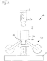
- Fig. 2 is again shown schematically how a coupling member 20 attached to the drill rod element 2 can be inserted axially into the sleeve-shaped coupling receptacle 30 on the drilling tool 7 in the direction of the arrow shown.
- the two locking bolts 50 can be pushed back radially outward into their unlocking position against the action of gravity of the adjustment mechanism 40 when a predetermined axial force is applied from the locking position shown.
- the locking bolts 50 can be moved back radially inward into their locking position by the force of gravity of the adjustment mechanism 40, the locking bolts 50 reaching into the locking recess 24 on the coupling member 20.
- the coupling member 20 is now received in the sleeve-shaped coupling receptacle 30 in an axially secured manner.
- FIG Fig. 3 An alternative embodiment of the adjustment mechanism 40 is shown schematically in FIG Fig. 3 shown.
- the locking bolt 50 is mounted in a radial direction in a suitable passage 35 in the wall of the sleeve-shaped coupling receptacle 30. In the locking position shown, the coupling bolt 50 protrudes inward into the receiving hole 33.
- the latter is connected to a connecting pin 52 with a Z-shaped, lever-like actuator 42.
- the actuator 42 is mounted on the coupling receptacle 30 so as to be pivotable about a pivot axis 43. Furthermore, the actuator 42 is provided with a link-like elongated hole 46 into which the connecting pin 52 of the locking bolt 50 protrudes.
- the actuator 42 Due to the weight of the actuator 42, it is moved down into the in Fig. 3 The position shown is pressed, the locking bolt 50 being advanced radially inward into the receiving hole 33 via the connecting pin 52.
- the actuator 42 By means of a handle-like unlocking device 60 at the free end of the actuator 42, the actuator 42 can be pivoted upward about the pivot axis 43.
- the locking bolt 50 is moved radially outward into its unlocking position.
- the upward force on the actuator 42 is eliminated, it can move back down due to its own weight, the locking bolt 50 being pushed back into the locking position.
- the adjustment mechanism 40 can in principle be designed in any other suitable manner, with a vertical alignment of the drill pipe coupling 10 exerting a sufficient weight force by which the locking bolt 50 is pushed radially inward into a locking position and held there.
Landscapes
- Engineering & Computer Science (AREA)
- Life Sciences & Earth Sciences (AREA)
- Geology (AREA)
- Mining & Mineral Resources (AREA)
- Mechanical Engineering (AREA)
- Physics & Mathematics (AREA)
- Environmental & Geological Engineering (AREA)
- Fluid Mechanics (AREA)
- General Life Sciences & Earth Sciences (AREA)
- Geochemistry & Mineralogy (AREA)
- Earth Drilling (AREA)
Abstract
Description
- Die Erfindung betrifft eine Bohrgestängekupplung mit einer hülsenförmigen Kupplungsaufnahme, einem zapfenförmigen Kupplungsglied, welches zum Bilden einer drehfesten Verbindung in die Kupplungsaufnahme axial einsteckbar ist, und mindestens einem Riegelbolzen, welcher quer zur axialen Kupplungsrichtung gerichtet ist, und sich in einer verriegelten Kupplungsposition von der Kupplungsaufnahme in eine Verriegelungsausnehmung an dem Kupplungsglied erstreckt, gemäß dem Oberbegriff des Anspruchs 1.
- Eine derartige Bohrgestängekupplung ist beispielsweise aus der
DE 10 2011 109 001 A1 bekannt. Diese Bohrgestängekupplung wird häufig auch als eine sogenannte Kellybox bezeichnet. In der eingesteckten Kupplungsposition wird eine axiale Verriegelung dadurch bewirkt, dass ein quer gerichteter Riegelbolzen in die Kupplungsaufnahme und das Kupplungsglied eingebracht wird, so dass eine formschlüssige Verbindung erreicht ist. - Die bekannte Bohrgestängekupplung erfordert jedoch sowohl beim Verriegeln als auch beim Entriegeln manuelle Tätigkeiten von Bedienpersonal. Diese sind grundsätzlich zeitaufwändig. Zudem können sich bei Bohrgestängeelementen, welche eine Länge von mehreren Metern aufweisen können und die in der Regel vertikal ausgerichtet sind, die Kupplungsanordnungen mehrere Meter über dem Boden befinden. Zur Betätigung werden daher Steighilfen oder sogar Hubfahrzeuge benötigt, was ebenfalls aufwändig ist. Zudem sind Arbeiten in größeren Höhen über dem Boden und auch im unmittelbaren Wirkungsbereich eines Bohrgestänges aus Gründen der Arbeitssicherheit problematisch und sollten daher auf ein erforderliches Mindestmaß reduziert werden.
- Der Erfindung liegt die Aufgabe zugrunde, eine Bohrgestängekupplung anzugeben, welche besonders einfach betätigbar ist.
- Nach der Erfindung wird die Aufgabe durch eine Bohrgestängekupplung mit den Merkmalen des Anspruchs 1 gelöst. Bevorzugte Ausführungsformen der Erfindung sind in den abhängigen Ansprüchen angegeben.
- Die erfindungsgemäße Bohrgestängekupplung ist dadurch gekennzeichnet, dass der Riegelbolzen mittels einer schwerkraftabhängigen Verstellmechanik an der hülsenförmigen Kupplungsaufnahme radial verstellbar zwischen einer Entriegelungsposition und einer Verriegelungsposition gelagert ist, dass die Verstellmechanik mindestens ein bewegbares Stellglied aufweist, welches zwischen einer unteren Einschubposition, in welcher der Riegelbolzen in die Verriegelungsposition geschoben ist, und einer oberen Rückzugsposition bewegbar ist, in welcher der Riegelbolzen aus der Verriegelungsaufnahme in die Entriegelungsposition rückgezogen ist, und dass das Stellglied durch die Schwerkraft in der unteren Einschubposition gehalten ist.
- Eine Grundidee der Erfindung kann darin gesehen werden, eine zumindest halbautomatische Bohrgestängekupplung vorzusehen, bei welcher der Riegelbolzen an der äußeren Kupplungsaufnahme durch eine schwerkraftabhängige Verstellmechanik zwischen einer Entriegelungsposition und einer Verriegelungsposition verstellbar ist. Die Verstellmechanik weist mindestens ein bewegbares Stellglied auf, welches durch die Schwerkraft nach unten gezogen wird, wobei durch die Verstellmechanik der Riegelbolzen in eine Einschubposition geschoben und darin gehalten wird.
- Zum Entriegeln ist es somit lediglich erforderlich, dass mindestens ein außenliegendes Stellglied entgegen der Schwerkraft in eine obere Rückzugsposition zu bewegen, wobei durch die Verstellmechanik der Riegelbolzen aus der Verriegelungsposition in die Entriegelungsposition rückgezogen wird. Zu einem erneuten Verriegeln ist lediglich die Haltekraft zu entfernen, welche das mindestens eine Stellglied in der oberen Rückzugsposition hält. Bei Entfallen dieser Haltekraft wird das Stellglied wieder in die untere Einschubposition bewegt, wobei der Riegelbolzen erneut in die Entriegelungsposition geschoben wird.
- Vorzugsweise kann so ein Bohrgestänge mit der Kupplungsaufnahme oder dem Kupplungsglied in einfacher Weise axial mit einem zugehörigen Kupplungsglied beziehungsweise einer Kupplungsaufnahme eines anderen Bohrgestängeelementes gekuppelt werden, wobei durch die axiale Einschubkraft der Riegelbolzen mit dem Stellglied entgegen der Schwerkraft kurzzeitig verdrängt wird, bis der Riegelbolzen durch die schwerkraftabhängige Verstellmechanik wieder zurück in die Verriegelungsposition geschoben wird, um die beiden Bohrgestängeelemente zu verriegeln. Das Kupplungsglied und der Riegelbolzen können an ihrem freien Ende hierzu angeschrägt sein.
- Nach einer Weiterbildung der Erfindung kann eine gewünschte Stellkraft auf das mindestens eine Stellglied dadurch erreicht werden, dass an dem mindestens einen Stellglied ein Lastgewicht angeordnet ist. Das Lastgewicht kann dabei lösbar an dem Stellglied angebracht sein. Durch ein entsprechendes Vergrößern oder Verkleinern des Lastgewichtes kann so eine gewünschte Stellkraft vorgegeben werden.
- Eine besonders zuverlässige Verbindung wird nach einer weiteren Ausführungsvariante der Erfindung dadurch erzielt, dass mehrere Riegelbolzen vorgesehen sind, welche, vorzugsweise gleichmäßig, verteilt über den Umfang der hülsenförmigen Kupplungsaufnahme angeordnet sind. Insbesondere können zwei bis vier Riegelbolzen verteilt um den Umfang der Kupplungsaufnahme angeordnet sein.
- Grundsätzlich kann die Verriegelungsausnehmung als ein Sackloch oder ein Durchgangsloch in dem Kupplungsglied ausgebildet sein. Besonders vorteilhaft ist es nach einer Ausführungsvariante der Erfindung, dass die Verriegelungsausnehmung als eine ringförmige Nut ausgebildet ist, welche sich entlang des Umfangs des zapfenförmigen Kupplungsglieds erstreckt. Bei einer derartigen Gestaltung der Verriegelungsausnehmung an der Außenseite des Kupplungsgliedes kann ein automatisches Kuppeln vorgesehen werden. Eine Querschnittskontur der Nut entspricht dabei einem Teil der Außenumfangskontur des Riegelbolzens. Vorzugsweise hat die Nut einen halbkreisförmigen Querschnitt.
- Grundsätzlich kann zum Entriegeln das bewegbare Stellglied der Verstellmechanik von Hand oder durch ein von Hand betätigtes Werkzeug nach oben geschoben werden, so dass der Riegelbolzen rückgezogen wird. Bevorzugt ist es nach einer Weiterbildung der Erfindung, dass an der Verstellmechanik eine Entriegelungseinrichtung angeordnet ist, mit welcher das mindestens eine Stellglied in die obere Rückzugsposition bewegbar ist. Die Entriegelungseinrichtung kann dabei energiebetätigt sein. Insbesondere kann eine Entriegelungseinrichtung etwa an einem Bohrantrieb vorgesehen sein, an welchem grundsätzlich bereits eine Energieversorgung vorgesehen ist. Die Entriegelungseinrichtung kann dabei elektrisch, hydraulisch oder pneumatisch betätigt werden.
- Nach einer Weiterbildung der Erfindung ist vorgesehen, dass die Entriegelungseinrichtung mit einer Betätigungsstange betätigbar ist. In einem einfachen Fall kann die Entriegelungseinrichtung ein einfaches Hakenelement oder eine sonstige Aufnahme für eine derartige mechanische Betätigung oder ein einfacher Handgriff sein.
- Dabei ist es besonders vorteilhaft, dass die Entriegelungseinrichtung ein Ringglied aufweist, an welchem ein oder mehrere Stellglieder angelenkt sind. Das Ringglied kann dabei die Kupplungsaufnahme ringförmig umgeben, so dass etwa bei Betätigung mit einer Betätigungsstange die Entriegelungseinrichtung von jeder Umfangsposition aus betätigt werden kann.
- Für eine besonders gute Drehmomentübertragung ist es nach einer Ausführungsvariante der Erfindung bevorzugt, dass die Kupplungsaufnahme und das Kupplungsglied eine polygonale Querschnittsform, insbesondere einen Vierkantquerschnitt aufweisen. Es ist jedoch auch ein dreieckiger oder sonstiger mehreckiger Querschnitt möglich, welcher eine Drehmomentübertragung zwischen der Kupplungsaufnahme und dem Kupplungsglied ermöglicht. Die entsprechenden Steckbereiche von Kupplungsaufnahme und Kupplungsglied sind dabei als eine Spielpassung ausgebildet.
- Weiterhin umfasst die Erfindung eine Bohrgestängeanordnung mit der zuvor beschriebenen Bohrgestängekupplung. Bevorzugt ist es dabei, dass die Bohrgestängekupplung zwischen zwei Bohrgestängeelementen angeordnet ist. Die Bohrgestängeelemente können dabei an ihrer Außenseite mit einer Förderwendel, Rührelementen oder ohne jegliche Elemente rein zylindrisch ausgebildet sein.
- Weiterhin ist nach der Erfindung eine Bohrgestängeanordnung mit einer solchen Bohrgestängekupplung vorgesehen, wobei die Bohrgestängekupplung zwischen einem Bohrgestängeelement und einem Bohrwerkzeug oder einem Bohrantrieb vorgesehen ist. Allgemein ist bei einer Bohrgestängeanordnung das zapfenförmige Kupplungsglied vorzugsweise oben angeordnet, während die hülsenförmige Kupplungsaufnahme relativ zum zugehörigen Kupplungsglied unten angeordnet ist. Als Bohrwerkzeug kann eine Bohrschnecke, ein Kastenbohrer, ein Verdrängerbohrer oder ein sonstiges Bohrwerkzeug vorgesehen werden, welches drehend angetrieben wird.
- Eine weitere vorteilhafte Ausgestaltung der Erfindung ergibt sich dadurch, dass die Kupplungsaufnahme und/oder das Kupplungsglied lösbar an einem Bohrgestängeelement, einem Bohrwerkzeug oder einem Bohrantrieb angebracht sind. Die Kupplungsaufnahme und/oder das Kupplungsglied können somit als eine Art Adapter zwischen der erfindungsgemäßen Bohrgestängekupplung und herkömmlichen Kupplungselementen, etwa einer Kellybox oder einem Kellysteckglied, ausgebildet sein. Dies ermöglicht auch eine einfache Nachrüstung bestehender Elemente.
- Die Erfindung wird nachfolgend anhand von bevorzugten Ausführungsbeispielen weiter erläutert, welche schematisch in den Zeichnungen dargestellt sind. In den Zeichnungen zeigen:
- Fig. 1
- eine schematische, teilgeschnittene Explosionsdarstellung einer erfindungsgemäßen Bohrgestängekupplung;
- Fig. 2
- eine schematische Darstellung der Bohrgestängekupplung von
Fig. 1 unmittelbar vor einem Zusammenstecken; und - Fig. 3
- eine Teilquerschnittsansicht zu einer möglichen Verstellmechanik für die erfindungsgemäße Bohrgestängekupplung.
- Gemäß
Fig. 1 weist eine erfindungsgemäße Bohrgestängekupplung 10 ein zapfenförmiges Kupplungsglied 20 auf, welches an einem nur teilweise dargestellten Bohrgestängeelement 2 angebracht wird. Das Kupplungsglied 20 kann grundsätzlich fest an dem Bohrgestängeelement 2 angeschweißt oder sogar daran einstückig ausgebildet sein. Bei der dargestellten Ausführungsform ist eine Nachrüstmöglichkeit dargestellt, wobei das Bohrgestängeelement 2 einen Verbindungsabschnitt 3 aufweist. Der Verbindungsabschnitt 3 kann eine herkömmliche Kellyverbindung mit einem Vierkantbereich sein. - Das zapfenförmige Kupplungsglied 20 weist einen zylindrischen Vorderabschnitt 22 und einen hülsenförmigen Rückabschnitt 26 auf. Der Verbindungsabschnitt 3 des Bohrgestängeelementes 2 kann passend und drehfest in den hülsenförmigen Rückabschnitt 26 des Kupplungsglieds 20 eingesteckt und durch quergerichtete Bolzen darin axial fixiert werden.
- Entlang des Außenumfangs des zapfenförmigen Vorderabschnitts 22 des Kupplungsglieds 20 ist eine ringförmige Nut 25 als eine Verriegelungsausnehmung 24 eingebracht. Die Nut 25 weist im Querschnitt etwa eine Halbkreisform auf. Weiter ist am freien Ende des Vorderabschnitts 22 ein verjüngender Kopf 23 mit einem nach unten abnehmenden Durchmesser ausgebildet.
- Die hülsenförmige Kupplungsaufnahme 30 wird in der dargestellten Ausführungsform an einem Bohrwerkzeug 7 angebracht. Das Bohrwerkzeug 7 weist einen schematisch dargestellten Grundkörper 8 auf, an dessen Oberseite zentrisch zu einer Längsachse ein hülsenförmiger Verbindungsbereich 9 angebracht ist. Das Bohrwerkzeug 7 kann beispielsweise ein Bohreimer mit einer entsprechenden Abtragseinrichtung zum Abtragen von Bodenmaterial sein. Grundsätzlich kann die hülsenförmige Kupplungsaufnahme 30 auch fest an dem Bohrwerkzeug 7 angebracht sein, etwa durch Schweißen.
- Die Kupplungsaufnahme 30 weist eine Umfangshülse 32 mit einem mittigen gestuften Aufnahmeloch 33 auf, welches vorzugsweise entsprechend einer Außenkontur des zapfenförmigen Kupplungsgliedes 20 einen viereckigen Querschnitt aufweist. Eine Unterseite der Umfangshülse 32 ist mit einem plattenförmigen Boden 34 verschlossen, an dessen Unterseite ein zapfenförmiges Verbindungselement 36 nach unten vorsteht. Das Verbindungselement 36 ist vorzugsweise gleich zu dem Verbindungsabschnitt 3 an dem Bohrgestängeelement 2 ausgebildet, so dass die Kupplungsaufnahme 30 ebenfalls in einfacher Weise als ein Nachrüstteil für bestehende Kellyverbindungen eingesetzt werden kann. Das zapfenförmige Verbindungselement 36, welches vorzugsweise als ein Vierkant ausgebildet ist, ist passend axial in den hülsenförmigen Verbindungsbereich 9 am Bohrwerkzeug 7 einsteckbar. Hierin kann es durch entsprechende quergerichtete Bolzen axial fixiert werden, so dass eine drehfeste und axial gesicherte Verbindung zwischen dem Bohrwerkzeug 7 und der Kupplungsaufnahme 30 gebildet ist.
- An der Kupplungsaufnahme 30 ist eine Verstellmechanik 40 angeordnet, welche in dem dargestellten Ausführungsbeispiel zwei hebelartige Stellglieder 42 aufweist, welche jeweils über eine Schwenkachse 43 an einem Durchgang an der Umfangshülse 32 der Kupplungsaufnahme 30 schwenkbar gelagert sind. Bei der dargestellten Ausführungsform ist ein Riegelbolzen 50 an einem nach innen in das Aufnahmeloch 33 hineinragenden freien Ende einstückig mit dem hebelförmigen Stellglied 42 ausgebildet. Über ein Lastgewicht 44 am äußeren Ende jedes Stellgliedes 42 ist dieses nach unten in eine Einschubposition gedrückt, bei welcher der Riegelbolzen 50 radial nach innen in das Aufnahmeloch 33 in eine Verriegelungsposition gedrückt oder geschoben ist.
- An den Lastgewichten 44 sind jeweils eine Ausnehmung 62 einer Entriegelungseinrichtung 60 ausgebildet. In die Ausnehmung 62 kann eine Betätigungsstange eingesetzt werden, mit welcher das Lastgewicht 44 und damit das Stellglied 42 nach oben in eine Rückzugsposition bewegt werden kann. Dabei wird der Riegelbolzen 50 radial nach außen in eine Entriegelungsposition geschoben, in welcher der Riegelbolzen 50 nicht mehr in eine Verriegelungsausnehmung 24 eines axial eingesteckten Kupplungsgliedes 20 eingreift. In dieser Entriegelungsposition kann somit ein Kupplungsglied 20 wieder aus der Kupplungsaufnahme 30 herausgezogen werden.
- In
Fig. 2 ist nochmals schematisch dargestellt, wie ein am Bohrgestängeelement 2 angebrachtes Kupplungsglied 20 in Richtung des gezeigten Pfeiles axial in die hülsenförmige Kupplungsaufnahme 30 am Bohrwerkzeug 7 eingesteckt werden kann. Bei diesem axialen Einstecken können die beiden Riegelbolzen 50 bei Aufbringen einer vorgegebenen Axialkraft aus der dargestellten Verriegelungsposition entgegen der Schwerkraftwirkung der Verstellmechanik 40 radial nach außen in ihre Entriegelungsposition rückgeschoben werden. Bei Erreichen der axialen Endposition des zapfenförmigen Kupplungsgliedes 20 können die Riegelbolzen 50 durch die Schwerkraftwirkung der Verstellmechanik 40 in ihre Verriegelungsposition radial nach innen rückbewegt werden, wobei die Riegelbolzen 50 in die Verriegelungsausnehmung 24 am Kupplungsglied 20 hineinreichen. In dieser Verriegelungsposition ist nunmehr das Kupplungsglied 20 axial gesichert in der hülsenförmigen Kupplungsaufnahme 30 aufgenommen. - Eine alternative Ausgestaltung der Verstellmechanik 40 ist schematisch in
Fig. 3 dargestellt. Dabei ist der Verriegelungsbolzen 50 radial gerichtet in einem passenden Durchgang 35 in der Wand der hülsenförmigen Kupplungsaufnahme 30 gelagert. In der dargestellten Verriegelungsposition ragt der Kupplungsbolzen 50 nach innen in das Aufnahmeloch 33 hinein. - Am radial äußeren Ende des Riegelbolzens 50 steht dieser mit einem Verbindungsstift 52 mit einem Z-förmigen, hebelartigen Stellglied 42 in Verbindung. Das Stellglied 42 ist um eine Schwenkachse 43 schwenkbar an der Kupplungsaufnahme 30 gelagert. Weiter ist das Stellglied 42 mit einem kulissenartigen Langloch 46 versehen, in welches der Verbindungsstift 52 des Riegelbolzens 50 hineinragt.
- Aufgrund des Eigengewichtes des Stellgliedes 42 wird dieses nach unten in die in
Fig. 3 gezeigte Position gedrückt, wobei über den Verbindungsstift 52 der Riegelbolzen 50 radial nach innen in das Aufnahmeloch 33 vorgeschoben wird. Durch eine handgriffartige Entriegelungseinrichtung 60 am freien Ende des Stellgliedes 42 kann das Stellglied 42 nach oben um die Schenkachse 43 geschwenkt werden. Hierdurch wird aufgrund der Verbindung über das Langloch 46 und den Verbindungsstift 52 der Riegelbolzen 50 radial nach außen in seine Entriegelungsposition bewegt. Sobald die nach oben gerichtete Kraft an dem Stellglied 42 entfällt, kann sich dieses aufgrund seines Eigengewichtes wieder zurück nach unten bewegen, wobei der Riegelbolzen 50 wieder zurück in die Verriegelungspositon geschoben wird. - Die Verstellmechanik 40 kann grundsätzlich in jeder anderen geeigneten Weise ausgebildet werden, wobei bei einer vertikalen Ausrichtung der Bohrgestängekupplung 10 eine hinreichende Gewichtskraft ausgeübt wird, durch welche der Riegelbolzen 50 radial nach innen in eine Verriegelungsposition geschoben und dort gehalten wird.
Claims (11)
- Bohrgestängekupplung mit- einer hülsenförmigen Kupplungsaufnahme (30),- einem zapfenförmigen Kupplungsglied (20), welches zum Bilden einer drehfesten Verbindung in die Kupplungsaufnahme (30) axial einsteckbar ist, und- mindestens einem Riegelbolzen (50), welcher quer zur axialen Kupplungsrichtung gerichtet ist und sich in einer verriegelten Kupplungsposition von der Kupplungsaufnahme (30) in eine Verriegelungsausnehmung (24) an dem Kupplungsglied (20) erstreckt,
dadurch gekennzeichnet,- dass der Riegelbolzen (50) mittels einer schwerkraftabhängigen Verstellmechanik (40) an der hülsenförmigen Kupplungsaufnahme (30) radial verstellbar zwischen einer Entriegelungsposition und einer Verriegelungsposition gelagert ist,- dass die Verstellmechanik (40) mindestens ein bewegbares Stellglied (42) aufweist, welches zwischen einer unteren Einschubposition, in welcher der Riegelbolzen (50) in die Verriegelungsposition geschoben ist, und einer oberen Rückzugsposition bewegbar ist, in welcher der Riegelbolzen (50) aus der Verriegelungsaufnahme (24) in die Entriegelungsposition rückgezogen ist, und- dass das Stellglied (42) durch die Schwerkraft in der unteren Einschubposition gehalten ist. - Bohrgestängekupplung nach Anspruch 1,
dadurch gekennzeichnet,
dass an dem mindestens einen Stellglied (42) ein Lastgewicht (44) angeordnet ist. - Bohrgestängekupplung nach Anspruch 1 oder 2,
dadurch gekennzeichnet,
dass mehrere Riegelbolzen (50) vorgesehen sind, welche, vorzugsweise gleichmäßig, verteilt über den Umfang der hülsenförmigen Kupplungsaufnahme (30) angeordnet sind. - Bohrgestängekupplung nach einem der Ansprüche 1 bis 3,
dadurch gekennzeichnet,
dass die Verriegelungsausnehmung (24) als eine ringförmige Nut (25) ausgebildet ist, welche sich entlang des Umfangs des zapfenförmigen Kupplungsglieds (20) erstreckt. - Bohrgestängekupplung nach einem der Ansprüche 1 bis 4,
dadurch gekennzeichnet,
dass an der Verstellmechanik (40) eine Entriegelungseinrichtung (60) angeordnet ist, mit welcher das mindestens eine Stellglied (42) in die obere Rückzugsposition bewegbar ist. - Bohrgestängekupplung nach Anspruch 5,
dadurch gekennzeichnet,
dass die Entriegelungseinrichtung (60) mit einer Betätigungsstange betätigbar ist. - Bohrgestängekupplung nach Anspruch 5 oder 6,
dadurch gekennzeichnet,
dass die Entriegelungseinrichtung (60) ein Ringglied aufweist, an welchem ein oder mehrere Stellglieder (42) angelenkt sind. - Bohrgestängekupplung nach einem der Ansprüche 1 bis 7,
dadurch gekennzeichnet,
dass die Kupplungsaufnahme (30) und das Kupplungsglied (20) eine polygonale Querschnittsform, insbesondere einen Vierkantquerschnitt, aufweisen. - Bohrgestängeanordnung mit einer Bohrgestängekupplung (10) nach einem der Ansprüche 1 bis 8,
dadurch gekennzeichnet,
dass die Bohrgestängekupplung (10) zwischen zwei Bohrgestängeelementen (2) vorgesehen ist. - Bohrgestängeanordnung mit einer Bohrgestängekupplung (10) nach einem der Ansprüche 1 bis 8,
dadurch gekennzeichnet,
dass die Bohrgestängekupplung (10) zwischen einem Bohrgestängeelement (2) und einem Bohrwerkzeug (7) oder einem Bohrantrieb vorgesehen ist. - Bohrgestängeanordnung nach Anspruch 9 oder 10,
dadurch gekennzeichnet.
dass die Kupplungsaufnahme (30) und/oder das Kupplungsglied (20) lösbar an einem Bohrgestängeelement (2), einem Bohrwerkzeug (7) oder einem Bohrantrieb angebracht sind.
Priority Applications (3)
| Application Number | Priority Date | Filing Date | Title |
|---|---|---|---|
| EP20174448.9A EP3910161B1 (de) | 2020-05-13 | 2020-05-13 | Bohrgestängekupplung |
| CN202180006091.8A CN114555904B (zh) | 2020-05-13 | 2021-04-15 | 钻杆接合器 |
| PCT/EP2021/059831 WO2021228489A1 (de) | 2020-05-13 | 2021-04-15 | Bohrgestängekupplung |
Applications Claiming Priority (1)
| Application Number | Priority Date | Filing Date | Title |
|---|---|---|---|
| EP20174448.9A EP3910161B1 (de) | 2020-05-13 | 2020-05-13 | Bohrgestängekupplung |
Publications (3)
| Publication Number | Publication Date |
|---|---|
| EP3910161A1 true EP3910161A1 (de) | 2021-11-17 |
| EP3910161C0 EP3910161C0 (de) | 2023-10-04 |
| EP3910161B1 EP3910161B1 (de) | 2023-10-04 |
Family
ID=70736575
Family Applications (1)
| Application Number | Title | Priority Date | Filing Date |
|---|---|---|---|
| EP20174448.9A Active EP3910161B1 (de) | 2020-05-13 | 2020-05-13 | Bohrgestängekupplung |
Country Status (3)
| Country | Link |
|---|---|
| EP (1) | EP3910161B1 (de) |
| CN (1) | CN114555904B (de) |
| WO (1) | WO2021228489A1 (de) |
Citations (4)
| Publication number | Priority date | Publication date | Assignee | Title |
|---|---|---|---|---|
| DE3642387A1 (de) * | 1986-12-11 | 1988-06-30 | Delmag Maschinenfabrik | Einrichtung zum indrehungsetzen und axialen bewegen von bohrrohrstraengen |
| DE102006022613A1 (de) * | 2006-05-15 | 2007-11-22 | Klemm Bohrtechnik Zweigniederlassung Der Bauer Maschinen Gmbh | Bohrantriebseinheit, Bohrgestängeelement und Bohrverfahren |
| DE102011109001A1 (de) | 2011-07-29 | 2013-01-31 | Abf-Bohrtechnik Gmbh & Co. Kg | Bohrgerät mit Kelly-Stange und äußere Werkzeugschnellbefestigung |
| EP3379018A2 (de) * | 2017-03-02 | 2018-09-26 | Weatherford Technology Holdings, LLC | Werkzeugkoppler mit gleitkoppelelementen für kraftdrehkopf |
Family Cites Families (6)
| Publication number | Priority date | Publication date | Assignee | Title |
|---|---|---|---|---|
| DE10129064A1 (de) * | 2001-06-15 | 2002-12-19 | Hilti Ag | Gesteinsbohrwerkzeug |
| US20100044113A1 (en) * | 2008-08-22 | 2010-02-25 | Coiled Tubing Rental Tools, Inc. | Connection for well bore drilling tools |
| CN102392611A (zh) * | 2011-10-14 | 2012-03-28 | 武汉武船机电设备有限责任公司 | 无出土螺纹钻杆及同时形成螺纹和光杆的无出土打桩方法 |
| US10526852B2 (en) * | 2017-06-19 | 2020-01-07 | Weatherford Technology Holdings, Llc | Combined multi-coupler with locking clamp connection for top drive |
| US10527104B2 (en) * | 2017-07-21 | 2020-01-07 | Weatherford Technology Holdings, Llc | Combined multi-coupler for top drive |
| AU2019213357A1 (en) * | 2018-10-05 | 2020-04-23 | Downhole Products Limited | Slimline Stop Collar |
-
2020
- 2020-05-13 EP EP20174448.9A patent/EP3910161B1/de active Active
-
2021
- 2021-04-15 WO PCT/EP2021/059831 patent/WO2021228489A1/de not_active Ceased
- 2021-04-15 CN CN202180006091.8A patent/CN114555904B/zh active Active
Patent Citations (4)
| Publication number | Priority date | Publication date | Assignee | Title |
|---|---|---|---|---|
| DE3642387A1 (de) * | 1986-12-11 | 1988-06-30 | Delmag Maschinenfabrik | Einrichtung zum indrehungsetzen und axialen bewegen von bohrrohrstraengen |
| DE102006022613A1 (de) * | 2006-05-15 | 2007-11-22 | Klemm Bohrtechnik Zweigniederlassung Der Bauer Maschinen Gmbh | Bohrantriebseinheit, Bohrgestängeelement und Bohrverfahren |
| DE102011109001A1 (de) | 2011-07-29 | 2013-01-31 | Abf-Bohrtechnik Gmbh & Co. Kg | Bohrgerät mit Kelly-Stange und äußere Werkzeugschnellbefestigung |
| EP3379018A2 (de) * | 2017-03-02 | 2018-09-26 | Weatherford Technology Holdings, LLC | Werkzeugkoppler mit gleitkoppelelementen für kraftdrehkopf |
Also Published As
| Publication number | Publication date |
|---|---|
| CN114555904B (zh) | 2026-04-03 |
| CN114555904A (zh) | 2022-05-27 |
| EP3910161C0 (de) | 2023-10-04 |
| WO2021228489A1 (de) | 2021-11-18 |
| EP3910161B1 (de) | 2023-10-04 |
Similar Documents
| Publication | Publication Date | Title |
|---|---|---|
| EP3910160B1 (de) | Bohrgestängekupplung und verfahren zum betätigen der bohrgestängekupplung | |
| DE2525163C2 (de) | Reibahle | |
| EP0546382B1 (de) | Handnietgerät | |
| DE2748093A1 (de) | Von hand betaetigbares werkzeug zur installation blinder ankermuttern | |
| EP3167973B1 (de) | Nietwerkzeug | |
| EP2770156B1 (de) | Bohrwerkzeug und Verfahren zum Erdbohren | |
| EP3195982A1 (de) | Spannvorrichtung für eine schraubverbindung, verfahren zum anziehen einer schraubverbindung sowie gewindemutter | |
| DE3642387C2 (de) | ||
| EP0688687A1 (de) | Hebevorrichtung | |
| DE102006022613B4 (de) | Bohrantriebseinheit und Bohrgerät | |
| EP3910161B1 (de) | Bohrgestängekupplung | |
| DE2903936C2 (de) | Vorrichtung zur Gewinnung von Kernen | |
| DE69621921T2 (de) | Ziehvorrichtung für einen meisselhalter | |
| EP4339417A1 (de) | Spannkopfanordnung zum spannen eines bohrgestängeelemtes | |
| EP4372202A1 (de) | Im-loch-bohrgerät und verfahren zum erstellen einer bohrung im boden | |
| DE20017358U1 (de) | Drehbohrgestänge | |
| EP1145876A1 (de) | Anhängerkupplung für Kfz | |
| EP4073341A1 (de) | Vorrichtung zum anschluss eines bohrrohres an den bohrantrieb eines bohrgerätes sowie bohranordnung für erdbohrungen mit einer solchen vorrichtung | |
| EP0383225A1 (de) | Einrichtung zum lösbaren Verbinden eines Drehtisches mit einem Bohrrohr | |
| DE1219885B (de) | Klemmvorrichtung fuer Bohrgestaenge oder Rohre | |
| EP1431003A1 (de) | Kraftspannfutter und Ausklinkschlüssel dafür | |
| DE20308853U1 (de) | Holzspaltevorrichtung | |
| EP0374788B1 (de) | Teleskop-Bohrgestänge | |
| DE10036119B4 (de) | Nietsetzgerät | |
| DE946041C (de) | Kerndrehbohrzeug fuer Tiefbohrungen mit ausziehbarem Kernrohr |
Legal Events
| Date | Code | Title | Description |
|---|---|---|---|
| PUAI | Public reference made under article 153(3) epc to a published international application that has entered the european phase |
Free format text: ORIGINAL CODE: 0009012 |
|
| STAA | Information on the status of an ep patent application or granted ep patent |
Free format text: STATUS: THE APPLICATION HAS BEEN PUBLISHED |
|
| AK | Designated contracting states |
Kind code of ref document: A1 Designated state(s): AL AT BE BG CH CY CZ DE DK EE ES FI FR GB GR HR HU IE IS IT LI LT LU LV MC MK MT NL NO PL PT RO RS SE SI SK SM TR |
|
| B565 | Issuance of search results under rule 164(2) epc |
Effective date: 20201102 |
|
| STAA | Information on the status of an ep patent application or granted ep patent |
Free format text: STATUS: REQUEST FOR EXAMINATION WAS MADE |
|
| 17P | Request for examination filed |
Effective date: 20220509 |
|
| RBV | Designated contracting states (corrected) |
Designated state(s): AL AT BE BG CH CY CZ DE DK EE ES FI FR GB GR HR HU IE IS IT LI LT LU LV MC MK MT NL NO PL PT RO RS SE SI SK SM TR |
|
| GRAP | Despatch of communication of intention to grant a patent |
Free format text: ORIGINAL CODE: EPIDOSNIGR1 |
|
| STAA | Information on the status of an ep patent application or granted ep patent |
Free format text: STATUS: GRANT OF PATENT IS INTENDED |
|
| INTG | Intention to grant announced |
Effective date: 20230525 |
|
| GRAS | Grant fee paid |
Free format text: ORIGINAL CODE: EPIDOSNIGR3 |
|
| GRAA | (expected) grant |
Free format text: ORIGINAL CODE: 0009210 |
|
| STAA | Information on the status of an ep patent application or granted ep patent |
Free format text: STATUS: THE PATENT HAS BEEN GRANTED |
|
| AK | Designated contracting states |
Kind code of ref document: B1 Designated state(s): AL AT BE BG CH CY CZ DE DK EE ES FI FR GB GR HR HU IE IS IT LI LT LU LV MC MK MT NL NO PL PT RO RS SE SI SK SM TR |
|
| REG | Reference to a national code |
Ref country code: GB Ref legal event code: FG4D Free format text: NOT ENGLISH |
|
| REG | Reference to a national code |
Ref country code: CH Ref legal event code: EP |
|
| REG | Reference to a national code |
Ref country code: IE Ref legal event code: FG4D Free format text: LANGUAGE OF EP DOCUMENT: GERMAN |
|
| REG | Reference to a national code |
Ref country code: DE Ref legal event code: R096 Ref document number: 502020005479 Country of ref document: DE |
|
| U01 | Request for unitary effect filed |
Effective date: 20231103 |
|
| U07 | Unitary effect registered |
Designated state(s): AT BE BG DE DK EE FI FR IT LT LU LV MT NL PT SE SI Effective date: 20231109 |
|
| PG25 | Lapsed in a contracting state [announced via postgrant information from national office to epo] |
Ref country code: GR Free format text: LAPSE BECAUSE OF FAILURE TO SUBMIT A TRANSLATION OF THE DESCRIPTION OR TO PAY THE FEE WITHIN THE PRESCRIBED TIME-LIMIT Effective date: 20240105 |
|
| PG25 | Lapsed in a contracting state [announced via postgrant information from national office to epo] |
Ref country code: IS Free format text: LAPSE BECAUSE OF FAILURE TO SUBMIT A TRANSLATION OF THE DESCRIPTION OR TO PAY THE FEE WITHIN THE PRESCRIBED TIME-LIMIT Effective date: 20240204 |
|
| PG25 | Lapsed in a contracting state [announced via postgrant information from national office to epo] |
Ref country code: ES Free format text: LAPSE BECAUSE OF FAILURE TO SUBMIT A TRANSLATION OF THE DESCRIPTION OR TO PAY THE FEE WITHIN THE PRESCRIBED TIME-LIMIT Effective date: 20231004 |
|
| PG25 | Lapsed in a contracting state [announced via postgrant information from national office to epo] |
Ref country code: IS Free format text: LAPSE BECAUSE OF FAILURE TO SUBMIT A TRANSLATION OF THE DESCRIPTION OR TO PAY THE FEE WITHIN THE PRESCRIBED TIME-LIMIT Effective date: 20240204 Ref country code: GR Free format text: LAPSE BECAUSE OF FAILURE TO SUBMIT A TRANSLATION OF THE DESCRIPTION OR TO PAY THE FEE WITHIN THE PRESCRIBED TIME-LIMIT Effective date: 20240105 Ref country code: ES Free format text: LAPSE BECAUSE OF FAILURE TO SUBMIT A TRANSLATION OF THE DESCRIPTION OR TO PAY THE FEE WITHIN THE PRESCRIBED TIME-LIMIT Effective date: 20231004 |
|
| PG25 | Lapsed in a contracting state [announced via postgrant information from national office to epo] |
Ref country code: RS Free format text: LAPSE BECAUSE OF FAILURE TO SUBMIT A TRANSLATION OF THE DESCRIPTION OR TO PAY THE FEE WITHIN THE PRESCRIBED TIME-LIMIT Effective date: 20231004 Ref country code: PL Free format text: LAPSE BECAUSE OF FAILURE TO SUBMIT A TRANSLATION OF THE DESCRIPTION OR TO PAY THE FEE WITHIN THE PRESCRIBED TIME-LIMIT Effective date: 20231004 Ref country code: NO Free format text: LAPSE BECAUSE OF FAILURE TO SUBMIT A TRANSLATION OF THE DESCRIPTION OR TO PAY THE FEE WITHIN THE PRESCRIBED TIME-LIMIT Effective date: 20240104 Ref country code: HR Free format text: LAPSE BECAUSE OF FAILURE TO SUBMIT A TRANSLATION OF THE DESCRIPTION OR TO PAY THE FEE WITHIN THE PRESCRIBED TIME-LIMIT Effective date: 20231004 |
|
| U20 | Renewal fee for the european patent with unitary effect paid |
Year of fee payment: 5 Effective date: 20240528 |
|
| REG | Reference to a national code |
Ref country code: DE Ref legal event code: R097 Ref document number: 502020005479 Country of ref document: DE |
|
| PG25 | Lapsed in a contracting state [announced via postgrant information from national office to epo] |
Ref country code: CZ Free format text: LAPSE BECAUSE OF FAILURE TO SUBMIT A TRANSLATION OF THE DESCRIPTION OR TO PAY THE FEE WITHIN THE PRESCRIBED TIME-LIMIT Effective date: 20231004 |
|
| PG25 | Lapsed in a contracting state [announced via postgrant information from national office to epo] |
Ref country code: SK Free format text: LAPSE BECAUSE OF FAILURE TO SUBMIT A TRANSLATION OF THE DESCRIPTION OR TO PAY THE FEE WITHIN THE PRESCRIBED TIME-LIMIT Effective date: 20231004 |
|
| PG25 | Lapsed in a contracting state [announced via postgrant information from national office to epo] |
Ref country code: SM Free format text: LAPSE BECAUSE OF FAILURE TO SUBMIT A TRANSLATION OF THE DESCRIPTION OR TO PAY THE FEE WITHIN THE PRESCRIBED TIME-LIMIT Effective date: 20231004 Ref country code: SK Free format text: LAPSE BECAUSE OF FAILURE TO SUBMIT A TRANSLATION OF THE DESCRIPTION OR TO PAY THE FEE WITHIN THE PRESCRIBED TIME-LIMIT Effective date: 20231004 Ref country code: RO Free format text: LAPSE BECAUSE OF FAILURE TO SUBMIT A TRANSLATION OF THE DESCRIPTION OR TO PAY THE FEE WITHIN THE PRESCRIBED TIME-LIMIT Effective date: 20231004 Ref country code: CZ Free format text: LAPSE BECAUSE OF FAILURE TO SUBMIT A TRANSLATION OF THE DESCRIPTION OR TO PAY THE FEE WITHIN THE PRESCRIBED TIME-LIMIT Effective date: 20231004 |
|
| PLBE | No opposition filed within time limit |
Free format text: ORIGINAL CODE: 0009261 |
|
| STAA | Information on the status of an ep patent application or granted ep patent |
Free format text: STATUS: NO OPPOSITION FILED WITHIN TIME LIMIT |
|
| 26N | No opposition filed |
Effective date: 20240705 |
|
| REG | Reference to a national code |
Ref country code: CH Ref legal event code: PL |
|
| PG25 | Lapsed in a contracting state [announced via postgrant information from national office to epo] |
Ref country code: MC Free format text: LAPSE BECAUSE OF FAILURE TO SUBMIT A TRANSLATION OF THE DESCRIPTION OR TO PAY THE FEE WITHIN THE PRESCRIBED TIME-LIMIT Effective date: 20231004 |
|
| GBPC | Gb: european patent ceased through non-payment of renewal fee |
Effective date: 20240513 |
|
| PG25 | Lapsed in a contracting state [announced via postgrant information from national office to epo] |
Ref country code: MC Free format text: LAPSE BECAUSE OF FAILURE TO SUBMIT A TRANSLATION OF THE DESCRIPTION OR TO PAY THE FEE WITHIN THE PRESCRIBED TIME-LIMIT Effective date: 20231004 Ref country code: CH Free format text: LAPSE BECAUSE OF NON-PAYMENT OF DUE FEES Effective date: 20240531 |
|
| PG25 | Lapsed in a contracting state [announced via postgrant information from national office to epo] |
Ref country code: IE Free format text: LAPSE BECAUSE OF NON-PAYMENT OF DUE FEES Effective date: 20240513 |
|
| PG25 | Lapsed in a contracting state [announced via postgrant information from national office to epo] |
Ref country code: GB Free format text: LAPSE BECAUSE OF NON-PAYMENT OF DUE FEES Effective date: 20240513 |
|
| U20 | Renewal fee for the european patent with unitary effect paid |
Year of fee payment: 6 Effective date: 20250520 |
|
| PG25 | Lapsed in a contracting state [announced via postgrant information from national office to epo] |
Ref country code: CY Free format text: LAPSE BECAUSE OF FAILURE TO SUBMIT A TRANSLATION OF THE DESCRIPTION OR TO PAY THE FEE WITHIN THE PRESCRIBED TIME-LIMIT; INVALID AB INITIO Effective date: 20200513 |
|
| PG25 | Lapsed in a contracting state [announced via postgrant information from national office to epo] |
Ref country code: HU Free format text: LAPSE BECAUSE OF FAILURE TO SUBMIT A TRANSLATION OF THE DESCRIPTION OR TO PAY THE FEE WITHIN THE PRESCRIBED TIME-LIMIT; INVALID AB INITIO Effective date: 20200513 |
|
| PG25 | Lapsed in a contracting state [announced via postgrant information from national office to epo] |
Ref country code: TR Free format text: LAPSE BECAUSE OF FAILURE TO SUBMIT A TRANSLATION OF THE DESCRIPTION OR TO PAY THE FEE WITHIN THE PRESCRIBED TIME-LIMIT Effective date: 20231004 |
|
| U20 | Renewal fee for the european patent with unitary effect paid |
Year of fee payment: 7 Effective date: 20260519 |