EP3909727B1 - Betätigungsvorrichtung - Google Patents
Betätigungsvorrichtung Download PDFInfo
- Publication number
- EP3909727B1 EP3909727B1 EP21173337.3A EP21173337A EP3909727B1 EP 3909727 B1 EP3909727 B1 EP 3909727B1 EP 21173337 A EP21173337 A EP 21173337A EP 3909727 B1 EP3909727 B1 EP 3909727B1
- Authority
- EP
- European Patent Office
- Prior art keywords
- support
- arm
- robot arm
- arm element
- respect
- Prior art date
- Legal status (The legal status is an assumption and is not a legal conclusion. Google has not performed a legal analysis and makes no representation as to the accuracy of the status listed.)
- Active
Links
Images



Classifications
-
- B—PERFORMING OPERATIONS; TRANSPORTING
- B25—HAND TOOLS; PORTABLE POWER-DRIVEN TOOLS; MANIPULATORS
- B25J—MANIPULATORS; CHAMBERS PROVIDED WITH MANIPULATION DEVICES
- B25J19/00—Accessories fitted to manipulators, e.g. for monitoring, for viewing; Safety devices combined with or specially adapted for use in connection with manipulators
- B25J19/02—Sensing devices
-
- B—PERFORMING OPERATIONS; TRANSPORTING
- B25—HAND TOOLS; PORTABLE POWER-DRIVEN TOOLS; MANIPULATORS
- B25J—MANIPULATORS; CHAMBERS PROVIDED WITH MANIPULATION DEVICES
- B25J9/00—Program-controlled manipulators
- B25J9/16—Program controls
- B25J9/1656—Program controls characterised by programming, planning systems for manipulators
- B25J9/1664—Program controls characterised by programming, planning systems for manipulators characterised by motion, path, trajectory planning
- B25J9/1666—Avoiding collision or forbidden zones
-
- B—PERFORMING OPERATIONS; TRANSPORTING
- B25—HAND TOOLS; PORTABLE POWER-DRIVEN TOOLS; MANIPULATORS
- B25J—MANIPULATORS; CHAMBERS PROVIDED WITH MANIPULATION DEVICES
- B25J9/00—Program-controlled manipulators
- B25J9/16—Program controls
- B25J9/1679—Program controls characterised by the tasks executed
- B25J9/1684—Tracking a line or surface by means of sensors
-
- B—PERFORMING OPERATIONS; TRANSPORTING
- B25—HAND TOOLS; PORTABLE POWER-DRIVEN TOOLS; MANIPULATORS
- B25J—MANIPULATORS; CHAMBERS PROVIDED WITH MANIPULATION DEVICES
- B25J13/00—Controls for manipulators
- B25J13/08—Controls for manipulators by means of sensing devices, e.g. viewing or touching devices
- B25J13/086—Proximity sensors
-
- B—PERFORMING OPERATIONS; TRANSPORTING
- B25—HAND TOOLS; PORTABLE POWER-DRIVEN TOOLS; MANIPULATORS
- B25J—MANIPULATORS; CHAMBERS PROVIDED WITH MANIPULATION DEVICES
- B25J19/00—Accessories fitted to manipulators, e.g. for monitoring, for viewing; Safety devices combined with or specially adapted for use in connection with manipulators
- B25J19/02—Sensing devices
- B25J19/027—Electromagnetic sensing devices
-
- B—PERFORMING OPERATIONS; TRANSPORTING
- B25—HAND TOOLS; PORTABLE POWER-DRIVEN TOOLS; MANIPULATORS
- B25J—MANIPULATORS; CHAMBERS PROVIDED WITH MANIPULATION DEVICES
- B25J19/00—Accessories fitted to manipulators, e.g. for monitoring, for viewing; Safety devices combined with or specially adapted for use in connection with manipulators
- B25J19/02—Sensing devices
- B25J19/04—Viewing devices
-
- B—PERFORMING OPERATIONS; TRANSPORTING
- B25—HAND TOOLS; PORTABLE POWER-DRIVEN TOOLS; MANIPULATORS
- B25J—MANIPULATORS; CHAMBERS PROVIDED WITH MANIPULATION DEVICES
- B25J19/00—Accessories fitted to manipulators, e.g. for monitoring, for viewing; Safety devices combined with or specially adapted for use in connection with manipulators
- B25J19/06—Safety devices
-
- B—PERFORMING OPERATIONS; TRANSPORTING
- B25—HAND TOOLS; PORTABLE POWER-DRIVEN TOOLS; MANIPULATORS
- B25J—MANIPULATORS; CHAMBERS PROVIDED WITH MANIPULATION DEVICES
- B25J9/00—Program-controlled manipulators
- B25J9/02—Program-controlled manipulators characterised by movement of the arms, e.g. cartesian coordinate type
- B25J9/04—Program-controlled manipulators characterised by movement of the arms, e.g. cartesian coordinate type by rotating at least one arm, excluding the head movement itself, e.g. cylindrical coordinate type or polar coordinate type
- B25J9/046—Revolute coordinate type
-
- B—PERFORMING OPERATIONS; TRANSPORTING
- B25—HAND TOOLS; PORTABLE POWER-DRIVEN TOOLS; MANIPULATORS
- B25J—MANIPULATORS; CHAMBERS PROVIDED WITH MANIPULATION DEVICES
- B25J9/00—Program-controlled manipulators
- B25J9/06—Program-controlled manipulators characterised by multi-articulated arms
-
- B—PERFORMING OPERATIONS; TRANSPORTING
- B25—HAND TOOLS; PORTABLE POWER-DRIVEN TOOLS; MANIPULATORS
- B25J—MANIPULATORS; CHAMBERS PROVIDED WITH MANIPULATION DEVICES
- B25J9/00—Program-controlled manipulators
- B25J9/10—Program-controlled manipulators characterised by positioning means for manipulator elements
- B25J9/106—Program-controlled manipulators characterised by positioning means for manipulator elements with articulated links
-
- B—PERFORMING OPERATIONS; TRANSPORTING
- B25—HAND TOOLS; PORTABLE POWER-DRIVEN TOOLS; MANIPULATORS
- B25J—MANIPULATORS; CHAMBERS PROVIDED WITH MANIPULATION DEVICES
- B25J9/00—Program-controlled manipulators
- B25J9/16—Program controls
-
- B—PERFORMING OPERATIONS; TRANSPORTING
- B25—HAND TOOLS; PORTABLE POWER-DRIVEN TOOLS; MANIPULATORS
- B25J—MANIPULATORS; CHAMBERS PROVIDED WITH MANIPULATION DEVICES
- B25J9/00—Program-controlled manipulators
- B25J9/16—Program controls
- B25J9/1674—Program controls characterised by safety, monitoring, diagnostic
-
- B—PERFORMING OPERATIONS; TRANSPORTING
- B25—HAND TOOLS; PORTABLE POWER-DRIVEN TOOLS; MANIPULATORS
- B25J—MANIPULATORS; CHAMBERS PROVIDED WITH MANIPULATION DEVICES
- B25J9/00—Program-controlled manipulators
- B25J9/16—Program controls
- B25J9/1674—Program controls characterised by safety, monitoring, diagnostic
- B25J9/1676—Avoiding collision or forbidden zones
-
- B—PERFORMING OPERATIONS; TRANSPORTING
- B25—HAND TOOLS; PORTABLE POWER-DRIVEN TOOLS; MANIPULATORS
- B25J—MANIPULATORS; CHAMBERS PROVIDED WITH MANIPULATION DEVICES
- B25J9/00—Program-controlled manipulators
- B25J9/16—Program controls
- B25J9/1694—Program controls characterised by use of sensors other than normal servo-feedback from position, speed or acceleration sensors, perception control, multi-sensor controlled systems, sensor fusion
-
- F—MECHANICAL ENGINEERING; LIGHTING; HEATING; WEAPONS; BLASTING
- F16—ENGINEERING ELEMENTS AND UNITS; GENERAL MEASURES FOR PRODUCING AND MAINTAINING EFFECTIVE FUNCTIONING OF MACHINES OR INSTALLATIONS; THERMAL INSULATION IN GENERAL
- F16M—FRAMES, CASINGS OR BEDS OF ENGINES, MACHINES OR APPARATUS, NOT SPECIFIC TO ENGINES, MACHINES OR APPARATUS PROVIDED FOR ELSEWHERE; STANDS; SUPPORTS
- F16M11/00—Stands or trestles as supports for apparatus or articles placed thereon ; Stands for scientific apparatus such as gravitational force meters
- F16M11/20—Undercarriages with or without wheels
- F16M11/2007—Undercarriages with or without wheels comprising means allowing pivoting adjustment
- F16M11/2021—Undercarriages with or without wheels comprising means allowing pivoting adjustment around a horizontal axis
-
- F—MECHANICAL ENGINEERING; LIGHTING; HEATING; WEAPONS; BLASTING
- F16—ENGINEERING ELEMENTS AND UNITS; GENERAL MEASURES FOR PRODUCING AND MAINTAINING EFFECTIVE FUNCTIONING OF MACHINES OR INSTALLATIONS; THERMAL INSULATION IN GENERAL
- F16M—FRAMES, CASINGS OR BEDS OF ENGINES, MACHINES OR APPARATUS, NOT SPECIFIC TO ENGINES, MACHINES OR APPARATUS PROVIDED FOR ELSEWHERE; STANDS; SUPPORTS
- F16M13/00—Other supports for positioning apparatus or articles; Means for steadying hand-held apparatus or articles
- F16M13/02—Other supports for positioning apparatus or articles; Means for steadying hand-held apparatus or articles for supporting on, or attaching to, an object, e.g. tree, gate, window-frame, cycle
-
- G—PHYSICS
- G05—CONTROLLING; REGULATING
- G05B—CONTROL OR REGULATING SYSTEMS IN GENERAL; FUNCTIONAL ELEMENTS OF SUCH SYSTEMS; MONITORING OR TESTING ARRANGEMENTS FOR SUCH SYSTEMS OR ELEMENTS
- G05B2219/00—Program-control systems
- G05B2219/30—Nc systems
- G05B2219/40—Robotics, robotics mapping to robotics vision
- G05B2219/40202—Human robot coexistence
Definitions
- the present invention relates to an operating device prearranged for operating in a working area accessible to working staff.
- the solutions in question usually envisage a plurality of presence sensors, in multiple positions around the device so as to provide one or more monitoring areas.
- the first type of known solution referred to above suffers from the drawback of being far from versatile on account of the fact that a new task to be assigned to the operating device can frequently require repositioning and reprogramming of the presence sensors in order to reconfigure the monitoring area.
- WO2018/145990A1 there is also known a monitoring system for a robot arm that combines the solution of providing a plurality of presence sensors around the robot arm to define a given monitoring area with the solution of providing a presence sensor on the operating unit of the robot arm itself to define a mobile monitoring area fixed with respect to the operating unit.
- This solution presents the drawback of being far from versatile for the same reasons referred to above with reference to the first type of known solutions discussed.
- the monitoring action performed by the mobile sensor with the operating unit of the robot proves far from effective in regard to the aim of guaranteeing a high level of safety for operators.
- the object of the present invention is to provide an operating device that is able to overcome the aforesaid drawbacks.
- the present invention regards an operating device prearranged for operating in a working area accessible to operating staff.
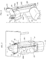
- the operating device described herein comprises a robot arm 10, which carries an operating unit 12 at its end.
- the robot arm 10 comprises a succession of arm elements 10i (illustrated in the example are the arm elements designated by 10I, 10II and 10III), which are mounted on one another in a rotatable way about respective axes of rotation Xi (illustrated in the example are the axes of rotation denoted by X1, X2, and X3), and which are driven in motion, individually or in a number of elements simultaneously, to move the operating unit 12 in space.
- arm elements 10i illustrated in the example are the arm elements designated by 10I, 10II and 10III
- Xi illustrated in the example are the axes of rotation denoted by X1, X2, and X3
- the robot arm 10 is an articulated robot arm with six axes of rotation.
- the robot arm illustrated is in any case provided merely by way of example.
- the operating device described herein may in fact envisage a robot arm of some other type, for example an anthropomorphic robot, a SCARA robot, etc., with or without a seventh axis of translation for displacement of the robot between different workstations.
- the robot arm 10 is prearranged for operating in a work space L for carrying out one or more tasks.
- the solution described herein has been devised with particular reference to the field of production and packaging in the foodstuff industry.
- the tasks mentioned may, for example, regard the treatment, and/or handling, and/or positioning, of products and/or parts of product, and/or of packages and/or parts of packages, and/or of production means and/or packaging means.
- the operating device can also be operatively associated to other devices or machinery for execution of the tasks referred to, for example conveying devices, such as conveyor belts, pallets, trolleys, benches, etc., or else further operating devices.
- conveying devices such as conveyor belts, pallets, trolleys, benches, etc., or else further operating devices.
- the operating device described herein may be used for operations of picking up and putting down products.
- the operating device described herein further comprises at least one presence sensor 14 for detecting the presence of persons or objects.
- the sensor or sensors 14 determine a monitoring volume.
- the device described herein is characterized in that the at least one presence sensor is carried by the robot arm itself by means of a positioning system that is able to keep, in a constant way, the presence sensor in a pre-set orientation, notwithstanding movement of the robot arm 10, in the work space L, for carrying out its tasks.
- the positioning system referred to comprises a support on which the at least one presence sensor 14 is carried and which is mounted on an element 10i of the robot arm in such a way as to be orientable, and a positioning unit prearranged for rotating the support with respect to the arm element 10i on which it is mounted, as a result of a movement of the robot arm, so as to keep the orientation of the support unchanged.
- the positioning system comprises a support 22, provided on which are a plurality of sensors 14 arranged in two parallel rows.
- the support 22 is, in particular, constituted by a plate bent to form a U having a base 22A and two sides 22B, opposite to one another and orthogonal to the base 22A.
- the two rows of sensors are mounted on the two sides 22B of the plate.
- the positioning unit comprises a four-bar linkage mechanism 24, which is constrained to the robot arm 10 and carries the support 22.
- the mechanism 24 operates to keep the support 22, and hence the sensors 14 arranged thereon, according to a pre-set orientation, so that the two rows of sensors 14 extend in respective vertical directions Z1, Z2, which are set at a distance apart in a horizontal direction Y ( Figure 2 ).
- the sensors 14 define monitoring volumes S1, S2, which are symmetrical with respect to the direction Y and extend on opposite sides of the robot arm 10 so to set themselves over areas alongside the robot that extend from the margins of the work space L ( Figure 4 ).
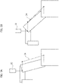
- the four-bar linkage mechanism 24 comprises a first lever 241, which is mounted at the coupling interface between the arm element 10I and the arm element 10II, and is fixed to the arm element 10I according to a horizontal orientation.
- the mechanism 24 further comprises a second lever 24II, which is mounted at the coupling interface between the arm element 10II and the arm element 10III, and is rotatable with respect to both of the two elements, about the axis of rotation X3, about which the arm element 10III is rotatably mounted on the arm element 10II.
- the mechanism 24 comprises a third lever 24III, which is rotatably connected at its opposite ends to the ends of the two levers 241 and 2411.
- the lever 2411 has an eccentric portion 24IIA, to which the support 22 is fixed.
- the support 22 is oriented with its base 22A set horizontally so as to keep the two rows of sensors 14 in the respective vertical directions Z1, Z2.
- the mechanism 24 is prearranged for varying the configuration of its levers, as a result of a movement of the arm element 10II about the axis of rotation X2, in order to keep the support 22 in its horizontal orientation.
- Figures 5A and 5B illustrate the robot arm 10, respectively, in a first condition in which the arm element 10II is set oriented at an angle of approximately 20° with respect to the vertical, and in a second condition in which the arm element 10II is set oriented at an angle of approximately 45°. From these figures it appears clearly that the variation of position of the arm element 10II causes a change of configuration in the mechanism 24 so that the support 22 is rotated with respect to the arm element 10II in order to remain in the horizontal condition.
- the monitoring volumes S1, S2 are kept constantly in line with the work space L.
- the positioning unit described constituted by the four-bar linkage mechanism 24, is provided merely by way of example.
- the positioning unit is constituted by a gyroscope system 44, comprising a rotor 441, rotatably mounted about an axis of rotation I, and a mobile frame 4411, which carries the rotor 441 and defines one or two axes of oscillation, about which the axis of rotation I can be oriented in space.
- the support 22 is mounted fixed to the module of the mobile frame that carries the rotor 44I.
- the axis of rotation I, and hence the support 22, remain in a pre-set orientation as a result of the angular momentum generated by the continuous rotation of the rotor 441 about the axis of rotation I, notwithstanding the movements of the robot arm 10 for executing the tasks assigned thereto.
- the positioning unit comprises an actuator 54 for moving the support 22 with respect to the arm element on which it is mounted, and a control unit (not illustrated) configured to control the actuator 54 on the basis of a signal indicating the position in space of the arm element, to keep the support 22 in the pre-set orientation.
- the aforementioned pre-set orientation of the support 22 and of the sensors 14 will preferably be a "horizontal" orientation, so that the positioning unit will be prearranged to intervene in order to keep the aforesaid orientation unaltered as a result of any movement of the arm element, by which the support 22 is carried, about a generic non-vertical axis (incidentally, it will be noted that here by “horizontal orientation” is meant a condition in which the support and/or the sensors are not necessarily arranged horizontally, but which, instead, is referenced with respect to a horizontal plane and envisages, with respect to this plane, that the distance of any one point of the support and of the sensors will be fixed and unchanged).
- the positioning unit will not intervene either during movements about a vertical axis or during rectilinear movements of the arm element, i.e., during movements that would not be able to alter the aforesaid pre-set orientation.
- the pre-set orientation of the support 22 and of the sensors 14 may be of some other type and the positioning unit will be prearranged to maintain this other orientation, in line with the modalities discussed above.
- the support 22 is advantageously mounted at a top point of the robot arm 10 positioned for operating in the work space L. This makes it possible to determine, through the sensors 14, monitoring volumes S1, S2 that come to intercept relatively extensive areas at quite a distance from the work space L.
- the solution described herein envisages determination of at least one monitoring volume, which is defined by the at least one presence sensor carried by the positioning system described above.
- the number, shape, and dimensions of the monitoring volumes may vary as a function of the specific applications.
- the monitoring volumes S1, S2 of the example illustrated are generically shaped like the sector of a sphere ( Figure 4 ). They are each formed by a set of sections (S1I, S1II, S1III and S2I, S2II, S2III), each section being determined by a single sensor 14.
- the monitoring volume S1 it comprises a first section S1I, a second section S1II, and a third section S1III, which each have a conical geometry and are oriented with their own geometrical axes according to angles, defined with respect to the horizontal plane of the floor, which progressively increase from the first section to the third section.
- the first section S1I is prearranged for identifying a possible presence of an operator immediately adjacent to the work space L.
- the second section S1II defines, instead, an area A1 of entry into the monitored area, which is positioned at a maximum distance from the work space L and through which it is possible to detect that an operator is approaching the work space.
- the third section S1III which faces upwards, is prearranged for detecting any object overhead approaching the work space L (for example, on overhead conveying systems, such as overhead travelling cranes or suspended conveying lines).
- the monitoring volume S2 is formed by the sections S2I, S2II, S2III according to the same modality.
- the sensors 14 may be of any known type, suited to the purposes referred to above.
- the sensors in question may be modules for emitting and receiving electromagnetic waves, prearranged for determining the positions and/or speeds of an object by analysing one or more characteristics of the signal generated from reception of the electromagnetic waves that are emitted by the module and then return to the same module, after being reflected by the object itself.
- the waves in question may, for example, be radio waves or microwaves.
- a type of sensor present on the market and suitable for the purposes referred to is represented by the safety radar sensor LBK ® marketed by the company LEUZE. Another type is constituted by position and displacement laser sensors.
- the sections (described above) of the monitoring volumes are determined by the beams of the electromagnetic waves emitted by the emitter and receiver modules. Consequently, the dimensions and geometries of the sections will depend upon the type of sensor used.
- the monitoring volumes provided by the device are used to establish conditions of safety for the members of the working staff that might approach or gain access to the work space L.
- a control unit 100 of the device can be configured to control different operating states of the robot arm 10 as a function of the signals coming from the sensors 14.
- the criteria and modalities with which to intervene on operation of the robot arm 10 can be established by standards currently in force in the various countries and in the various sectors of activity.
- control unit 100 of the device can control operation of the robot arm 10, according to a mode of displacement at lower speeds at the moment when the sensors 14 detect that an operator is crossing the entry area A1, and then issue a command for complete arrest of the robot arm 10 at the moment when the sensors 14 detect the presence of the operator in the working area, close to the work space L, that is intercepted by the monitoring volume S1I.
Landscapes
- Engineering & Computer Science (AREA)
- Mechanical Engineering (AREA)
- Robotics (AREA)
- General Engineering & Computer Science (AREA)
- Human Computer Interaction (AREA)
- Physics & Mathematics (AREA)
- Electromagnetism (AREA)
- Manipulator (AREA)
Claims (10)
- Betätigungsvorrichtung, die dazu konfiguriert ist, in einem Arbeitsbereich (L) tätig zu sein, umfassend:- einen Roboterarm (10), der eine Abfolge von Armelementen (10i) umfasst, die aneinander in rotierbarer Weise um entsprechende Rotationsachsen (Xi) angebracht sind, und der eine Betätigungseinheit (12) an seinem Ende trägt; und- zumindest einen Anwesenheitssensor (14), der zum Erkennen der Anwesenheit eines Bedieners vorgesehen ist;wobei die Betätigungsvorrichtung dadurch gekennzeichnet ist, dass sie ein Positionierungssystem aufweist, das eine Stütze (22) umfasst, durch die der zumindest eine Anwesenheitssensor (14) getragen wird und die an einem Armelement (10II) des Roboterarms gemäß einer voreingestellten Orientierung und derart angebracht ist, dass sie bezüglich des Armelements (10II) orientierbar ist, dadurch gekennzeichnet, dassdas Positionierungssystem ferner eine Positionierungseinheit (24; 44; 54) umfasst, die zum Rotieren der Stütze (22) bezüglich des Armelements (10II) als Ergebnis einer Bewegung des Roboterarms vorgesehen ist, um die voreingestellte Orientierung der Stütze (22) unverändert beizubehalten.
- Betätigungsvorrichtung nach Anspruch 1, bei der die Stütze (22) an einem Zwischenarmelement (10II) der Abfolge von Armelementen des Roboterarms angebracht ist.
- Betätigungsvorrichtung nach Anspruch 1 oder 2, bei der der Roboterarm ein Robotergelenkarm ist, der eine Abfolge von sechs Armelementen (10i) umfasst, die aneinander in rotierbarer Weise um sechs entsprechende Rotationsachsen (Xi) angebracht sind, und bei der die Stütze (22) an dem zweiten Armelement (10II), ausgehend von einer Basis, auf der der Roboterarm angebracht ist, angebracht ist.
- Betätigungsvorrichtung nach einem der vorhergehenden Ansprüche, bei der der zumindest eine Anwesenheitssensor (14) ein Überwachungsvolumen (S1, S2) bestimmt, das bezogen auf den Roboterarm (10) seitlich ausgerichtet ist und einen Einlassbereich (A1) zum Erkennen eines sich dem Arbeitsbereich (L) annähernden Bedieners definiert.
- Betätigungsvorrichtung nach Anspruch 4, umfassend eine Vielzahl von Anwesenheitssensoren (14), die gegenseitig angeordnet sind, um zumindest ein Überwachungsvolumen (S1, S2) zu bilden, das vorgegebene Abmessungen und eine Geometrie hat.
- Betätigungsvorrichtung nach einem der vorhergehenden Ansprüche, bei der der Anwesenheitssensor (14) ein Modul zum Senden und Empfangen elektromagnetischer Wellen ist.
- Betätigungsvorrichtung nach einem der vorhergehenden Ansprüche, bei der die Positionierungseinheit einen vierstängigen Kopplungsmechanismus (24) umfasst, der mit der Stütze (22) und dem Armelement (10II), auf dem die Stütze angebracht ist, verbunden ist, und zum Rotieren der Stütze (22) bezüglich des Armelements (10II) als Ergebnis einer Bewegung des Armelements (10II) um die entsprechende Rotationsachse (X2) tätig ist, um die Stütze (22) in der voreingestellten Orientierung zu halten.
- Betätigungsvorrichtung nach einem der vorhergehenden Ansprüche, bei der die Positionierungseinheit ein Gyroskopsystem (44) umfasst, das die Stütze (22) trägt und tätig ist, um die Stütze in der voreingestellten Orientierung zu halten als Ergebnis einer Bewegung des Roboterarms (10).
- Betätigungsvorrichtung nach einem der vorhergehenden Ansprüche, bei der die Positionierungseinheit einen Aktor (54) zum Bewegen der Stütze (22) bezüglich des Armelements, auf dem sie angebracht ist, und eine Steuereinheit umfasst, die dazu konfiguriert ist, den Aktor (54) in Abhängigkeit der Position des Armelements zu steuern, um die Stütze in der voreingestellten Orientierung zu halten.
- Betätigungsvorrichtung nach einem der vorhergehenden Ansprüche, die eine Steuereinheit (100) umfasst, die dazu konfiguriert ist, den Roboterarm in Abhängigkeit von Signalen, die von dem zumindest einen Anwesenheitssensor (14) kommen, in einen Sicherheitszustand zu fahren.
Applications Claiming Priority (1)
| Application Number | Priority Date | Filing Date | Title |
|---|---|---|---|
| IT202000010804 | 2020-05-12 |
Publications (2)
| Publication Number | Publication Date |
|---|---|
| EP3909727A1 EP3909727A1 (de) | 2021-11-17 |
| EP3909727B1 true EP3909727B1 (de) | 2022-12-28 |
Family
ID=71784550
Family Applications (1)
| Application Number | Title | Priority Date | Filing Date |
|---|---|---|---|
| EP21173337.3A Active EP3909727B1 (de) | 2020-05-12 | 2021-05-11 | Betätigungsvorrichtung |
Country Status (8)
| Country | Link |
|---|---|
| US (1) | US11801603B2 (de) |
| EP (1) | EP3909727B1 (de) |
| JP (1) | JP7707478B2 (de) |
| KR (1) | KR20210139169A (de) |
| CN (1) | CN113650054B (de) |
| CA (1) | CA3117643A1 (de) |
| IL (1) | IL283101B2 (de) |
| PL (1) | PL3909727T3 (de) |
Families Citing this family (3)
| Publication number | Priority date | Publication date | Assignee | Title |
|---|---|---|---|---|
| KR102518382B1 (ko) | 2021-10-19 | 2023-04-06 | 주식회사 베터리얼 | 탄소나노튜브 분산액, 이의 제조방법, 이를 포함하는 전극 슬러리 조성물, 이를 포함하는 전극 및 이를 포함하는 리튬 이차전지 |
| DE102022131773A1 (de) | 2022-11-30 | 2024-06-06 | Pilz Gmbh & Co. Kg | Sicherheitsvorrichtung zum Absichern eines Gefahrenbereichs einer automatisiert arbeitenden Maschine, insbesondere eines Roboters |
| DE102022131775A1 (de) | 2022-11-30 | 2024-06-06 | Pilz Gmbh & Co. Kg | Sicherheitsvorrichtung zum Absichern eines Gefahrenbereichs einer automatisiert arbeitenden Maschine, insbesondere eines Roboters |
Family Cites Families (35)
| Publication number | Priority date | Publication date | Assignee | Title |
|---|---|---|---|---|
| US4831549A (en) * | 1987-07-28 | 1989-05-16 | Brigham Young University | Device and method for correction of robot inaccuracy |
| JP2005219161A (ja) * | 2004-02-05 | 2005-08-18 | Matsushita Electric Ind Co Ltd | ロボット把持制御装置及びロボット把持制御システム |
| CN100556623C (zh) * | 2004-10-19 | 2009-11-04 | 松下电器产业株式会社 | 自动机械装置 |
| JP4460528B2 (ja) * | 2004-12-14 | 2010-05-12 | 本田技研工業株式会社 | 識別対象識別装置およびそれを備えたロボット |
| GB0608927D0 (en) * | 2006-05-08 | 2006-06-14 | Accentus Plc | Catalytic Reactor |
| DE202007010884U1 (de) * | 2007-08-03 | 2007-09-27 | Sick Ag | Überwachungsvorrichtung mit Nachführung des Bildsensors, um ein gefährdendes bewegliches Maschinenteil im Sichtfeld zu halten |
| JP4648486B2 (ja) * | 2009-01-26 | 2011-03-09 | ファナック株式会社 | 人間とロボットとの協調動作領域を有する生産システム |
| DE102012014249B4 (de) * | 2012-07-19 | 2014-04-03 | Audi Ag | Schutzvorrichtung zur Bewegungsabsicherung eines über mehrere Achsen verstellbaren Roboterarms |
| US9452532B2 (en) * | 2014-01-27 | 2016-09-27 | Panasonic Intellectual Property Management Co., Ltd. | Robot, device and method for controlling robot, and computer-readable non-transitory recording medium |
| EP3135445B1 (de) * | 2014-03-28 | 2021-04-28 | Sony Corporation | Roboterarmvorrichtung |
| US9737371B2 (en) * | 2014-09-30 | 2017-08-22 | Auris Surgical Robotics, Inc. | Configurable robotic surgical system with virtual rail and flexible endoscope |
| EP3017920B1 (de) * | 2014-11-07 | 2017-08-23 | Comau S.p.A. | Industrieroboter und verfahren zur steuerung eines industrieroboters |
| JP6364096B2 (ja) * | 2014-12-26 | 2018-07-25 | 川崎重工業株式会社 | ロボットシステム |
| DE102015200428B3 (de) * | 2015-01-14 | 2016-03-17 | Kuka Roboter Gmbh | Verfahren zur Ausrichtung eines mehrachsigen Manipulators mit einem Eingabegerät |
| US9408452B1 (en) * | 2015-11-19 | 2016-08-09 | Khaled A. M. A. A. Al-Khulaifi | Robotic hair dryer holder system with tracking |
| EP3389955A2 (de) * | 2015-12-16 | 2018-10-24 | MBL Limited | Robotische küche mit einem roboter, einer speicheranordnung und behälter dafür |
| JP6351900B2 (ja) * | 2016-05-26 | 2018-07-04 | 三菱電機株式会社 | ロボット制御装置 |
| CN107717982B (zh) * | 2016-08-12 | 2020-09-25 | 财团法人工业技术研究院 | 机械手臂的控制装置及操作方法 |
| EP3513300B1 (de) * | 2016-09-16 | 2025-11-12 | Verb Surgical Inc. | Sensor mit mehreren freiheitsgraden |
| CA3034639C (en) * | 2016-09-16 | 2021-03-23 | Verb Surgical Inc. | Robotic arms |
| EP3529675B1 (de) * | 2016-10-21 | 2022-12-14 | Trumpf Werkzeugmaschinen GmbH + Co. KG | Innenraum-personenortung-basierte fertigungssteuerung in der metallverarbeitenden industrie |
| JP6479264B2 (ja) * | 2017-01-13 | 2019-03-06 | 三菱電機株式会社 | 協働ロボットシステム、及びその制御方法 |
| DE102017202004A1 (de) | 2017-02-08 | 2018-08-09 | Thyssenkrupp Ag | Vorrichtung zur Absicherung eines maschinell gesteuerten Handhabungsgeräts und Verfahren |
| CN206493338U (zh) * | 2017-02-22 | 2017-09-15 | 韩山师范学院 | 一种可记录位移的自平衡及避障的机械臂 |
| JP2018176397A (ja) * | 2017-04-21 | 2018-11-15 | オムロン株式会社 | ロボットシステム |
| JP7049069B2 (ja) * | 2017-05-19 | 2022-04-06 | 川崎重工業株式会社 | ロボットシステム及びロボットシステムの制御方法 |
| CA3030734C (en) * | 2017-06-16 | 2023-01-10 | Robotiq Inc. | Robotic arm camera system and method |
| EP3418010B1 (de) * | 2017-06-23 | 2019-09-18 | Comau S.p.A. | Funktionelle anordnung für eine industrielle maschine, insbesondere für einen roboter, mit einer betriebseinheit mit einer sicherheitsabdeckung |
| JP7329902B2 (ja) * | 2017-08-25 | 2023-08-21 | オムロン株式会社 | ロボット制御装置、ロボットシステム、ロボット制御方法、および、ロボット制御プログラム |
| JP7206638B2 (ja) * | 2018-06-01 | 2023-01-18 | セイコーエプソン株式会社 | ロボット、制御装置およびロボットの制御方法 |
| EP3578319B1 (de) * | 2018-06-07 | 2021-01-20 | Sick Ag | Verfahren zum absichern einer gefahrenstelle |
| EP3578320B1 (de) * | 2018-06-07 | 2021-09-15 | Sick Ag | Konfigurieren einer von einem 3d-sensor überwachten gefahrenstelle |
| JP7155660B2 (ja) * | 2018-06-26 | 2022-10-19 | セイコーエプソン株式会社 | ロボット制御装置およびロボットシステム |
| US10795342B1 (en) * | 2019-04-01 | 2020-10-06 | The Boeing Company | Proximity detection in assembly environments having machinery |
| CN110507417A (zh) * | 2019-08-30 | 2019-11-29 | 上海声勤信息科技有限公司 | 一种手术室医用机械臂防撞系统 |
-
2021
- 2021-05-10 JP JP2021079552A patent/JP7707478B2/ja active Active
- 2021-05-10 CA CA3117643A patent/CA3117643A1/en active Pending
- 2021-05-10 US US17/315,808 patent/US11801603B2/en active Active
- 2021-05-11 KR KR1020210060620A patent/KR20210139169A/ko active Pending
- 2021-05-11 EP EP21173337.3A patent/EP3909727B1/de active Active
- 2021-05-11 PL PL21173337.3T patent/PL3909727T3/pl unknown
- 2021-05-11 IL IL283101A patent/IL283101B2/en unknown
- 2021-05-12 CN CN202110517673.4A patent/CN113650054B/zh active Active
Also Published As
| Publication number | Publication date |
|---|---|
| CN113650054B (zh) | 2025-04-22 |
| EP3909727A1 (de) | 2021-11-17 |
| JP7707478B2 (ja) | 2025-07-15 |
| CA3117643A1 (en) | 2021-11-12 |
| IL283101A (en) | 2021-12-01 |
| JP2021178400A (ja) | 2021-11-18 |
| US20210354296A1 (en) | 2021-11-18 |
| KR20210139169A (ko) | 2021-11-22 |
| CN113650054A (zh) | 2021-11-16 |
| US11801603B2 (en) | 2023-10-31 |
| PL3909727T3 (pl) | 2023-05-08 |
| IL283101B1 (en) | 2024-07-01 |
| IL283101B2 (en) | 2024-11-01 |
Similar Documents
| Publication | Publication Date | Title |
|---|---|---|
| US11801603B2 (en) | Operating device | |
| US11325259B2 (en) | Monitor system for robot and robot system | |
| US7783386B2 (en) | Device and method for safeguarding a machine-controlled handling device | |
| CN103260834B (zh) | 用于操纵机构尤其工业机器人的安全装置和运行安全装置的方法 | |
| EP3248740B1 (de) | Zaunfreies industrierobotersystem | |
| CN103381605B (zh) | 用于机器人装置的位置监测的监测装置及含其的生产系统 | |
| US12459123B2 (en) | Robot system with object detecting sensors | |
| KR20220123059A (ko) | 안전 장치, 자주식 로봇 시스템 및 제어 방법 | |
| US11638996B2 (en) | Robot | |
| WO2017085928A1 (ja) | ロボット | |
| JPWO2013175554A1 (ja) | ロボットおよびロボットシステム | |
| EP4273658B1 (de) | Verfahren und vorrichtung zur verarbeitung von palettengabelkollisionen sowie roboter, vorrichtung, medium und produkt | |
| US20260091498A1 (en) | Robot system with object detecting sensors | |
| Lien et al. | Embedding radars in robots for safety and obstacle detection | |
| JP2018144136A (ja) | ロボットシステム | |
| EP3838476B1 (de) | Werkzeugmaschinen für industrielle bearbeitungsvorgänge umfassend ein system zur überwachung ihrer betriebssicherheit, und verfahren dafür | |
| KR20230112356A (ko) | 안전영역 자동감지 다관절 로봇 | |
| WO2010060475A1 (en) | Industrial robot | |
| EP4070921A1 (de) | Sicherheitssystem für einen kollaborativen roboter | |
| WO1987006731A1 (en) | Oscillating scanner arrangement | |
| KR100542207B1 (ko) | 로봇의 작업자 감지 안전 시스템 | |
| CN207645220U (zh) | 一种输送小车的防侧翻系统 | |
| US20250339970A1 (en) | System and method for controlling operation of a robot | |
| KR20250087970A (ko) | 센서를 포함하는 로봇 및 그 제어 방법 | |
| KR102953843B1 (ko) | 오브젝트와 장치 표면 사이의 최소 거리를 결정하기 위한 방법, 장치 표면을 갖는 핸들링 장치용 안전 디바이스, 및 핸들링 장치 |
Legal Events
| Date | Code | Title | Description |
|---|---|---|---|
| PUAI | Public reference made under article 153(3) epc to a published international application that has entered the european phase |
Free format text: ORIGINAL CODE: 0009012 |
|
| STAA | Information on the status of an ep patent application or granted ep patent |
Free format text: STATUS: THE APPLICATION HAS BEEN PUBLISHED |
|
| AK | Designated contracting states |
Kind code of ref document: A1 Designated state(s): AL AT BE BG CH CY CZ DE DK EE ES FI FR GB GR HR HU IE IS IT LI LT LU LV MC MK MT NL NO PL PT RO RS SE SI SK SM TR |
|
| B565 | Issuance of search results under rule 164(2) epc |
Effective date: 20211008 |
|
| STAA | Information on the status of an ep patent application or granted ep patent |
Free format text: STATUS: REQUEST FOR EXAMINATION WAS MADE |
|
| 17P | Request for examination filed |
Effective date: 20220412 |
|
| RBV | Designated contracting states (corrected) |
Designated state(s): AL AT BE BG CH CY CZ DE DK EE ES FI FR GB GR HR HU IE IS IT LI LT LU LV MC MK MT NL NO PL PT RO RS SE SI SK SM TR |
|
| GRAP | Despatch of communication of intention to grant a patent |
Free format text: ORIGINAL CODE: EPIDOSNIGR1 |
|
| STAA | Information on the status of an ep patent application or granted ep patent |
Free format text: STATUS: GRANT OF PATENT IS INTENDED |
|
| RIC1 | Information provided on ipc code assigned before grant |
Ipc: B25J 9/04 20060101ALI20220722BHEP Ipc: B25J 9/16 20060101ALI20220722BHEP Ipc: B25J 19/02 20060101ALI20220722BHEP Ipc: B25J 19/06 20060101AFI20220722BHEP |
|
| INTG | Intention to grant announced |
Effective date: 20220826 |
|
| GRAS | Grant fee paid |
Free format text: ORIGINAL CODE: EPIDOSNIGR3 |
|
| GRAA | (expected) grant |
Free format text: ORIGINAL CODE: 0009210 |
|
| STAA | Information on the status of an ep patent application or granted ep patent |
Free format text: STATUS: THE PATENT HAS BEEN GRANTED |
|
| AK | Designated contracting states |
Kind code of ref document: B1 Designated state(s): AL AT BE BG CH CY CZ DE DK EE ES FI FR GB GR HR HU IE IS IT LI LT LU LV MC MK MT NL NO PL PT RO RS SE SI SK SM TR |
|
| REG | Reference to a national code |
Ref country code: GB Ref legal event code: FG4D |
|
| REG | Reference to a national code |
Ref country code: CH Ref legal event code: EP |
|
| REG | Reference to a national code |
Ref country code: DE Ref legal event code: R096 Ref document number: 602021001084 Country of ref document: DE |
|
| REG | Reference to a national code |
Ref country code: AT Ref legal event code: REF Ref document number: 1540171 Country of ref document: AT Kind code of ref document: T Effective date: 20230115 |
|
| REG | Reference to a national code |
Ref country code: IE Ref legal event code: FG4D |
|
| REG | Reference to a national code |
Ref country code: LT Ref legal event code: MG9D |
|
| PG25 | Lapsed in a contracting state [announced via postgrant information from national office to epo] |
Ref country code: SE Free format text: LAPSE BECAUSE OF FAILURE TO SUBMIT A TRANSLATION OF THE DESCRIPTION OR TO PAY THE FEE WITHIN THE PRESCRIBED TIME-LIMIT Effective date: 20221228 Ref country code: NO Free format text: LAPSE BECAUSE OF FAILURE TO SUBMIT A TRANSLATION OF THE DESCRIPTION OR TO PAY THE FEE WITHIN THE PRESCRIBED TIME-LIMIT Effective date: 20230328 Ref country code: LT Free format text: LAPSE BECAUSE OF FAILURE TO SUBMIT A TRANSLATION OF THE DESCRIPTION OR TO PAY THE FEE WITHIN THE PRESCRIBED TIME-LIMIT Effective date: 20221228 Ref country code: FI Free format text: LAPSE BECAUSE OF FAILURE TO SUBMIT A TRANSLATION OF THE DESCRIPTION OR TO PAY THE FEE WITHIN THE PRESCRIBED TIME-LIMIT Effective date: 20221228 |
|
| REG | Reference to a national code |
Ref country code: NL Ref legal event code: MP Effective date: 20221228 |
|
| REG | Reference to a national code |
Ref country code: AT Ref legal event code: MK05 Ref document number: 1540171 Country of ref document: AT Kind code of ref document: T Effective date: 20221228 |
|
| PG25 | Lapsed in a contracting state [announced via postgrant information from national office to epo] |
Ref country code: RS Free format text: LAPSE BECAUSE OF FAILURE TO SUBMIT A TRANSLATION OF THE DESCRIPTION OR TO PAY THE FEE WITHIN THE PRESCRIBED TIME-LIMIT Effective date: 20221228 Ref country code: LV Free format text: LAPSE BECAUSE OF FAILURE TO SUBMIT A TRANSLATION OF THE DESCRIPTION OR TO PAY THE FEE WITHIN THE PRESCRIBED TIME-LIMIT Effective date: 20221228 Ref country code: HR Free format text: LAPSE BECAUSE OF FAILURE TO SUBMIT A TRANSLATION OF THE DESCRIPTION OR TO PAY THE FEE WITHIN THE PRESCRIBED TIME-LIMIT Effective date: 20221228 Ref country code: GR Free format text: LAPSE BECAUSE OF FAILURE TO SUBMIT A TRANSLATION OF THE DESCRIPTION OR TO PAY THE FEE WITHIN THE PRESCRIBED TIME-LIMIT Effective date: 20230329 |
|
| PG25 | Lapsed in a contracting state [announced via postgrant information from national office to epo] |
Ref country code: NL Free format text: LAPSE BECAUSE OF FAILURE TO SUBMIT A TRANSLATION OF THE DESCRIPTION OR TO PAY THE FEE WITHIN THE PRESCRIBED TIME-LIMIT Effective date: 20221228 |
|
| P01 | Opt-out of the competence of the unified patent court (upc) registered |
Effective date: 20230529 |
|
| PG25 | Lapsed in a contracting state [announced via postgrant information from national office to epo] |
Ref country code: SM Free format text: LAPSE BECAUSE OF FAILURE TO SUBMIT A TRANSLATION OF THE DESCRIPTION OR TO PAY THE FEE WITHIN THE PRESCRIBED TIME-LIMIT Effective date: 20221228 Ref country code: RO Free format text: LAPSE BECAUSE OF FAILURE TO SUBMIT A TRANSLATION OF THE DESCRIPTION OR TO PAY THE FEE WITHIN THE PRESCRIBED TIME-LIMIT Effective date: 20221228 Ref country code: PT Free format text: LAPSE BECAUSE OF FAILURE TO SUBMIT A TRANSLATION OF THE DESCRIPTION OR TO PAY THE FEE WITHIN THE PRESCRIBED TIME-LIMIT Effective date: 20230428 Ref country code: ES Free format text: LAPSE BECAUSE OF FAILURE TO SUBMIT A TRANSLATION OF THE DESCRIPTION OR TO PAY THE FEE WITHIN THE PRESCRIBED TIME-LIMIT Effective date: 20221228 Ref country code: EE Free format text: LAPSE BECAUSE OF FAILURE TO SUBMIT A TRANSLATION OF THE DESCRIPTION OR TO PAY THE FEE WITHIN THE PRESCRIBED TIME-LIMIT Effective date: 20221228 Ref country code: CZ Free format text: LAPSE BECAUSE OF FAILURE TO SUBMIT A TRANSLATION OF THE DESCRIPTION OR TO PAY THE FEE WITHIN THE PRESCRIBED TIME-LIMIT Effective date: 20221228 Ref country code: AT Free format text: LAPSE BECAUSE OF FAILURE TO SUBMIT A TRANSLATION OF THE DESCRIPTION OR TO PAY THE FEE WITHIN THE PRESCRIBED TIME-LIMIT Effective date: 20221228 |
|
| PG25 | Lapsed in a contracting state [announced via postgrant information from national office to epo] |
Ref country code: SK Free format text: LAPSE BECAUSE OF FAILURE TO SUBMIT A TRANSLATION OF THE DESCRIPTION OR TO PAY THE FEE WITHIN THE PRESCRIBED TIME-LIMIT Effective date: 20221228 Ref country code: IS Free format text: LAPSE BECAUSE OF FAILURE TO SUBMIT A TRANSLATION OF THE DESCRIPTION OR TO PAY THE FEE WITHIN THE PRESCRIBED TIME-LIMIT Effective date: 20230428 Ref country code: AL Free format text: LAPSE BECAUSE OF FAILURE TO SUBMIT A TRANSLATION OF THE DESCRIPTION OR TO PAY THE FEE WITHIN THE PRESCRIBED TIME-LIMIT Effective date: 20221228 |
|
| REG | Reference to a national code |
Ref country code: DE Ref legal event code: R097 Ref document number: 602021001084 Country of ref document: DE |
|
| PG25 | Lapsed in a contracting state [announced via postgrant information from national office to epo] |
Ref country code: DK Free format text: LAPSE BECAUSE OF FAILURE TO SUBMIT A TRANSLATION OF THE DESCRIPTION OR TO PAY THE FEE WITHIN THE PRESCRIBED TIME-LIMIT Effective date: 20221228 |
|
| PLBE | No opposition filed within time limit |
Free format text: ORIGINAL CODE: 0009261 |
|
| STAA | Information on the status of an ep patent application or granted ep patent |
Free format text: STATUS: NO OPPOSITION FILED WITHIN TIME LIMIT |
|
| 26N | No opposition filed |
Effective date: 20230929 |
|
| PG25 | Lapsed in a contracting state [announced via postgrant information from national office to epo] |
Ref country code: MC Free format text: LAPSE BECAUSE OF FAILURE TO SUBMIT A TRANSLATION OF THE DESCRIPTION OR TO PAY THE FEE WITHIN THE PRESCRIBED TIME-LIMIT Effective date: 20221228 |
|
| REG | Reference to a national code |
Ref country code: BE Ref legal event code: MM Effective date: 20230531 |
|
| PG25 | Lapsed in a contracting state [announced via postgrant information from national office to epo] |
Ref country code: SI Free format text: LAPSE BECAUSE OF FAILURE TO SUBMIT A TRANSLATION OF THE DESCRIPTION OR TO PAY THE FEE WITHIN THE PRESCRIBED TIME-LIMIT Effective date: 20221228 Ref country code: MC Free format text: LAPSE BECAUSE OF FAILURE TO SUBMIT A TRANSLATION OF THE DESCRIPTION OR TO PAY THE FEE WITHIN THE PRESCRIBED TIME-LIMIT Effective date: 20221228 Ref country code: LU Free format text: LAPSE BECAUSE OF NON-PAYMENT OF DUE FEES Effective date: 20230511 |
|
| REG | Reference to a national code |
Ref country code: IE Ref legal event code: MM4A |
|
| PG25 | Lapsed in a contracting state [announced via postgrant information from national office to epo] |
Ref country code: IE Free format text: LAPSE BECAUSE OF NON-PAYMENT OF DUE FEES Effective date: 20230511 |
|
| PG25 | Lapsed in a contracting state [announced via postgrant information from national office to epo] |
Ref country code: IE Free format text: LAPSE BECAUSE OF NON-PAYMENT OF DUE FEES Effective date: 20230511 |
|
| PG25 | Lapsed in a contracting state [announced via postgrant information from national office to epo] |
Ref country code: BE Free format text: LAPSE BECAUSE OF NON-PAYMENT OF DUE FEES Effective date: 20230531 |
|
| PG25 | Lapsed in a contracting state [announced via postgrant information from national office to epo] |
Ref country code: BG Free format text: LAPSE BECAUSE OF FAILURE TO SUBMIT A TRANSLATION OF THE DESCRIPTION OR TO PAY THE FEE WITHIN THE PRESCRIBED TIME-LIMIT Effective date: 20221228 |
|
| PG25 | Lapsed in a contracting state [announced via postgrant information from national office to epo] |
Ref country code: BG Free format text: LAPSE BECAUSE OF FAILURE TO SUBMIT A TRANSLATION OF THE DESCRIPTION OR TO PAY THE FEE WITHIN THE PRESCRIBED TIME-LIMIT Effective date: 20221228 |
|
| PGFP | Annual fee paid to national office [announced via postgrant information from national office to epo] |
Ref country code: PL Payment date: 20250506 Year of fee payment: 5 Ref country code: DE Payment date: 20250423 Year of fee payment: 5 |
|
| PGFP | Annual fee paid to national office [announced via postgrant information from national office to epo] |
Ref country code: IT Payment date: 20250423 Year of fee payment: 5 |
|
| PGFP | Annual fee paid to national office [announced via postgrant information from national office to epo] |
Ref country code: FR Payment date: 20250423 Year of fee payment: 5 |
|
| PGFP | Annual fee paid to national office [announced via postgrant information from national office to epo] |
Ref country code: CH Payment date: 20250601 Year of fee payment: 5 |
|
| PG25 | Lapsed in a contracting state [announced via postgrant information from national office to epo] |
Ref country code: CY Free format text: LAPSE BECAUSE OF FAILURE TO SUBMIT A TRANSLATION OF THE DESCRIPTION OR TO PAY THE FEE WITHIN THE PRESCRIBED TIME-LIMIT; INVALID AB INITIO Effective date: 20210511 |
|
| PG25 | Lapsed in a contracting state [announced via postgrant information from national office to epo] |
Ref country code: HU Free format text: LAPSE BECAUSE OF FAILURE TO SUBMIT A TRANSLATION OF THE DESCRIPTION OR TO PAY THE FEE WITHIN THE PRESCRIBED TIME-LIMIT; INVALID AB INITIO Effective date: 20210511 |
|
| PG25 | Lapsed in a contracting state [announced via postgrant information from national office to epo] |
Ref country code: TR Free format text: LAPSE BECAUSE OF FAILURE TO SUBMIT A TRANSLATION OF THE DESCRIPTION OR TO PAY THE FEE WITHIN THE PRESCRIBED TIME-LIMIT Effective date: 20221228 |
|
| GBPC | Gb: european patent ceased through non-payment of renewal fee |
Effective date: 20250511 |
|
| PG25 | Lapsed in a contracting state [announced via postgrant information from national office to epo] |
Ref country code: GB Free format text: LAPSE BECAUSE OF NON-PAYMENT OF DUE FEES Effective date: 20250511 |