EP3909637A1 - Flush enhancing male luer tip design for syringes and any luer connector - Google Patents
Flush enhancing male luer tip design for syringes and any luer connector Download PDFInfo
- Publication number
- EP3909637A1 EP3909637A1 EP21170373.1A EP21170373A EP3909637A1 EP 3909637 A1 EP3909637 A1 EP 3909637A1 EP 21170373 A EP21170373 A EP 21170373A EP 3909637 A1 EP3909637 A1 EP 3909637A1
- Authority
- EP
- European Patent Office
- Prior art keywords
- flow
- lumen
- connection device
- expansion channel
- luer connection
- Prior art date
- Legal status (The legal status is an assumption and is not a legal conclusion. Google has not performed a legal analysis and makes no representation as to the accuracy of the status listed.)
- Pending
Links
- 230000002708 enhancing effect Effects 0.000 title description 2
- 239000012530 fluid Substances 0.000 claims abstract description 47
- 230000002792 vascular Effects 0.000 claims description 21
- 238000004891 communication Methods 0.000 claims description 6
- 238000001990 intravenous administration Methods 0.000 claims description 6
- 238000011144 upstream manufacturing Methods 0.000 claims description 5
- 241000237509 Patinopecten sp. Species 0.000 claims description 3
- 235000020637 scallop Nutrition 0.000 claims description 3
- 238000011010 flushing procedure Methods 0.000 description 25
- 239000008280 blood Substances 0.000 description 13
- 210000004369 blood Anatomy 0.000 description 13
- 238000000034 method Methods 0.000 description 5
- 208000015181 infectious disease Diseases 0.000 description 4
- 208000007536 Thrombosis Diseases 0.000 description 3
- 230000015572 biosynthetic process Effects 0.000 description 3
- 239000003814 drug Substances 0.000 description 3
- 230000002093 peripheral effect Effects 0.000 description 3
- 230000004323 axial length Effects 0.000 description 2
- 238000004140 cleaning Methods 0.000 description 2
- 239000000463 material Substances 0.000 description 2
- 230000000813 microbial effect Effects 0.000 description 2
- 238000012986 modification Methods 0.000 description 2
- 230000004048 modification Effects 0.000 description 2
- 206010040047 Sepsis Diseases 0.000 description 1
- 230000000845 anti-microbial effect Effects 0.000 description 1
- 208000037815 bloodstream infection Diseases 0.000 description 1
- 230000001010 compromised effect Effects 0.000 description 1
- 238000010276 construction Methods 0.000 description 1
- 238000011161 development Methods 0.000 description 1
- 230000018109 developmental process Effects 0.000 description 1
- 230000000694 effects Effects 0.000 description 1
- 238000001802 infusion Methods 0.000 description 1
- 238000002642 intravenous therapy Methods 0.000 description 1
- 239000007788 liquid Substances 0.000 description 1
- 230000000541 pulsatile effect Effects 0.000 description 1
- 238000005201 scrubbing Methods 0.000 description 1
- 230000001225 therapeutic effect Effects 0.000 description 1
Images


Classifications
-
- A—HUMAN NECESSITIES
- A61—MEDICAL OR VETERINARY SCIENCE; HYGIENE
- A61M—DEVICES FOR INTRODUCING MEDIA INTO, OR ONTO, THE BODY; DEVICES FOR TRANSDUCING BODY MEDIA OR FOR TAKING MEDIA FROM THE BODY; DEVICES FOR PRODUCING OR ENDING SLEEP OR STUPOR
- A61M39/00—Tubes, tube connectors, tube couplings, valves, access sites or the like, specially adapted for medical use
- A61M39/10—Tube connectors; Tube couplings
-
- A—HUMAN NECESSITIES
- A61—MEDICAL OR VETERINARY SCIENCE; HYGIENE
- A61M—DEVICES FOR INTRODUCING MEDIA INTO, OR ONTO, THE BODY; DEVICES FOR TRANSDUCING BODY MEDIA OR FOR TAKING MEDIA FROM THE BODY; DEVICES FOR PRODUCING OR ENDING SLEEP OR STUPOR
- A61M25/00—Catheters; Hollow probes
- A61M25/01—Introducing, guiding, advancing, emplacing or holding catheters
- A61M25/06—Body-piercing guide needles or the like
- A61M25/0606—"Over-the-needle" catheter assemblies, e.g. I.V. catheters
-
- A—HUMAN NECESSITIES
- A61—MEDICAL OR VETERINARY SCIENCE; HYGIENE
- A61M—DEVICES FOR INTRODUCING MEDIA INTO, OR ONTO, THE BODY; DEVICES FOR TRANSDUCING BODY MEDIA OR FOR TAKING MEDIA FROM THE BODY; DEVICES FOR PRODUCING OR ENDING SLEEP OR STUPOR
- A61M39/00—Tubes, tube connectors, tube couplings, valves, access sites or the like, specially adapted for medical use
- A61M39/22—Valves or arrangement of valves
-
- A—HUMAN NECESSITIES
- A61—MEDICAL OR VETERINARY SCIENCE; HYGIENE
- A61M—DEVICES FOR INTRODUCING MEDIA INTO, OR ONTO, THE BODY; DEVICES FOR TRANSDUCING BODY MEDIA OR FOR TAKING MEDIA FROM THE BODY; DEVICES FOR PRODUCING OR ENDING SLEEP OR STUPOR
- A61M5/00—Devices for bringing media into the body in a subcutaneous, intra-vascular or intramuscular way; Accessories therefor, e.g. filling or cleaning devices, arm-rests
- A61M5/178—Syringes
-
- A—HUMAN NECESSITIES
- A61—MEDICAL OR VETERINARY SCIENCE; HYGIENE
- A61M—DEVICES FOR INTRODUCING MEDIA INTO, OR ONTO, THE BODY; DEVICES FOR TRANSDUCING BODY MEDIA OR FOR TAKING MEDIA FROM THE BODY; DEVICES FOR PRODUCING OR ENDING SLEEP OR STUPOR
- A61M25/00—Catheters; Hollow probes
- A61M25/0043—Catheters; Hollow probes characterised by structural features
- A61M2025/0062—Catheters; Hollow probes characterised by structural features having features to improve the sliding of one part within another by using lubricants or surfaces with low friction
-
- A—HUMAN NECESSITIES
- A61—MEDICAL OR VETERINARY SCIENCE; HYGIENE
- A61M—DEVICES FOR INTRODUCING MEDIA INTO, OR ONTO, THE BODY; DEVICES FOR TRANSDUCING BODY MEDIA OR FOR TAKING MEDIA FROM THE BODY; DEVICES FOR PRODUCING OR ENDING SLEEP OR STUPOR
- A61M25/00—Catheters; Hollow probes
- A61M25/0067—Catheters; Hollow probes characterised by the distal end, e.g. tips
- A61M25/0068—Static characteristics of the catheter tip, e.g. shape, atraumatic tip, curved tip or tip structure
- A61M2025/0073—Tip designed for influencing the flow or the flow velocity of the fluid, e.g. inserts for twisted or vortex flow
-
- A—HUMAN NECESSITIES
- A61—MEDICAL OR VETERINARY SCIENCE; HYGIENE
- A61M—DEVICES FOR INTRODUCING MEDIA INTO, OR ONTO, THE BODY; DEVICES FOR TRANSDUCING BODY MEDIA OR FOR TAKING MEDIA FROM THE BODY; DEVICES FOR PRODUCING OR ENDING SLEEP OR STUPOR
- A61M39/00—Tubes, tube connectors, tube couplings, valves, access sites or the like, specially adapted for medical use
- A61M39/10—Tube connectors; Tube couplings
- A61M2039/1077—Adapters, e.g. couplings adapting a connector to one or several other connectors
-
- A—HUMAN NECESSITIES
- A61—MEDICAL OR VETERINARY SCIENCE; HYGIENE
- A61M—DEVICES FOR INTRODUCING MEDIA INTO, OR ONTO, THE BODY; DEVICES FOR TRANSDUCING BODY MEDIA OR FOR TAKING MEDIA FROM THE BODY; DEVICES FOR PRODUCING OR ENDING SLEEP OR STUPOR
- A61M39/00—Tubes, tube connectors, tube couplings, valves, access sites or the like, specially adapted for medical use
- A61M39/10—Tube connectors; Tube couplings
- A61M2039/1094—Tube connectors; Tube couplings at least partly incompatible with standard connectors, e.g. to prevent fatal mistakes in connection
-
- A—HUMAN NECESSITIES
- A61—MEDICAL OR VETERINARY SCIENCE; HYGIENE
- A61M—DEVICES FOR INTRODUCING MEDIA INTO, OR ONTO, THE BODY; DEVICES FOR TRANSDUCING BODY MEDIA OR FOR TAKING MEDIA FROM THE BODY; DEVICES FOR PRODUCING OR ENDING SLEEP OR STUPOR
- A61M39/00—Tubes, tube connectors, tube couplings, valves, access sites or the like, specially adapted for medical use
- A61M39/22—Valves or arrangement of valves
- A61M2039/229—Stopcocks
Definitions
- An aspect of the invention relates generally to a luer connection device, and more particularly to a luer connection device a housing including a side wall having an inside surface defining a lumen with a central axis, a proximal end, and a distal end including a male luer tip within the lumen having a central flow diverter extending outwardly from the central axis to direct a fluid to a circumferential dead space distal to the male luer tip.
- Another aspect of the invention relates a luer connection device having a flow expansion channel disposed in the lumen tapering outward from the wall of tubular housing and partially extending along a longitudinal axis from the tip opening toward the base opening for increasing mixing and flow through a circumferential dead space in the fluid path distal to the male luer tip.
- Yet another aspect of the invention relates a luer connection device having both a central flow diverter and a flow expansion channel disposed within the lumen.
- VADs Vascular Access Devices
- VADs are commonly used therapeutic devices and include intravenous catheters, syringes, extension sets, stop cocks, tubing, high pressure extension tubing, and needleless access devices.
- the operation of VADs is often compromised or completely prevented by the occurrence of thrombus formation.
- Thrombosis is the development of a blood clot within a vessel and/or vascular access device. If not properly maintained, VADs can become occluded.
- standards of practice have been developed. These standards include a cleaning procedure, which is commonly referred to as a flush procedure.
- the purpose of flushing is to clean the accumulated residue from dead-space located between male and female luer connections.
- the common flushing practice creates a turbulent flow during flushing to promote a "scrubbing" effect in the lumen and at the tip of the catheter.
- Embodiments of the present invention are directed to a luer connection device including a housing having a side wall with an inside surface defining a lumen with a central axis, a proximal end, and a distal end including a male luer tip within the lumen having a passageway therethrough providing fluid communication between the proximal end and the distal end.
- the male luer tip disposed within the lumen at or near the distal end including a central flow diverter extending outwardly from the central axis to direct a fluid to a circumferential dead space distal to the male luer tip.
- the luer connection device may also include at least one flow expansion channel for increasing flow and mixing a fluid through a circumferential dead space in the fluid path distal to the male luer tip.
- the flow expansion channel can be configured to extend in a straight taper outwardly from the central axis of the lumen. In one or more embodiments, the flow expansion channel may be configured to extend in a rotational taper outwardly from the central axis of the lumen.
- the flow expansion channel can be located upstream from the flow diverter.
- the proximal end of the luer connection device can be integrally connected to a vascular access device.
- the vascular access device may be a syringe, extension set, intravenous set, stop cock, tubing, high pressure extension tubing, or needleless access device.
- the luer connection device can be removably connected to a vascular access device.
- the central flow path diverter comprises a plurality of vanes.
- the plurality of vanes may have a tapered leading edge and tapered tailing edge to minimize drag and reduce resistance.
- the tapered leading edge may be configured to create a smooth entrance of fluid and the tapered tailing edge is configured to create a sharp exit for producing turbulent fluid flow upon exiting the flow diverter.
- the plurality of vanes may be configured to extend straight outwardly from the central axis of the lumen to the side wall. In one variation, the plurality of vanes extend outwardly from the central axis of the lumen in a curved configuration. At least one edge of the plurality of vanes can have a ramped angled surface to create a greater angle of incidence.
- the central flow path diverter can be configured in various shapes, for example, in a cross, rectangle, star, triangle, oval, spiral, twisting or helical formation.
- An aspect invention pertains to a luer connection device including a housing having a side wall with an inside surface defining a lumen, a proximal end and a distal end including a distal wall with an elongate male luer tip extending in a distal direction therefrom having a passageway therethrough providing fluid communication between the proximal end and the distal end; and a flow expansion channel being disposed in the lumen tapering outward from the wall of tubular housing and partially extending along a longitudinal axis from the tip opening toward the base opening for increasing mixing and flow through a circumferential dead space in the fluid path distal to the male luer tip.
- the proximal end can be integrally connected to a vascular access device.
- the vascular access device may be a syringe, extension set, intravenous set, stop cock, tubing, high pressure extension tubing, or needleless access device.
- the syringe is a pre-filled flush syringe.
- the luer connection device can be removably connected to a vascular access device.
- the flow expansion channel can be configured to extend in a straight taper outwardly from the central axis of the lumen.
- the flow expansion channel may be configured to extend in a rotational taper outwardly from the central axis of the lumen.
- the flow expansion channel may be configured to scallop outwardly from the central axis of the lumen.
- the flow expansion channel is located at the distal end and projects axially in a proximal direction towards the proximal end.
- the luer connection device also includes a flow diverter disposed in the lumen at or near the distal end of the male luer tip to direct the fluid flow to the periphery of a connecting female luer space upon application of force in the distal direction.
- the flow diverter can extend beyond the distal end of the housing.
- the flow diverter may be connected to the flow expansion channel.
- the flow expansion channel may be located upstream from the flow diverter.
- the flow diverter can direct fluid flow into the flow expansion channel.
- the flow expansion channel directs fluid flow into the flow diverter.
- the flow expansion channel and flow diverter are both configured to extend in a straight taper towards the central axis of the lumen.
- the flow expansion channel is configured to extend in a rotational taper towards the central axis of the lumen and flow diverter is configured to extend in a straight taper towards the central axis of the lumen.
- the flow diverter is configured to extend in a rotational taper towards the central axis of the lumen and flow expansion channel is configured to extend in a straight taper towards the central axis of the lumen.
- the distal end of the device is the end closest to a patient and the proximal end of the device is the end away from the patient and closest to a practitioner.
- VADs have luer fittings which contain male luer tips.
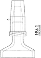
- Figure 1 shows zones of flow stagnation, depicted as "A", where blood-derived debris can typically form in a standard prior art luer connection device having a standard male luer tip straight central fluid path.
- the present invention overcomes problems associated with known flushing techniques by providing a luer connection device having a male luer tip that effectively scrubs the blood, residue and other debris from deadspace located between male and female luer connections.
- the present invention provides a luer connection device having a male luer tip with internal geometry that promotes improved flushing of any male to female luer connection whether it is connecting to a catheter, extension set, IV set, IV access device or any connector that includes a male luer for connection to a female luer.
- the luer connection device may be a stand alone component or may be integrally connected to a vascular access device that requires enhanced flushing prior to being connected to the female luer connection and performing the flush procedure.
- the luer connection device of the present invention includes a male luer tip having a flow diverter 80 and/or flow channels 90 in a variety of forms to improve the removal of blood in the systems for a given flush volume.
- the present invention may also be useful for flushing needless IV access valves, such as BD Q-Syte TM .
- the luer connection device of the present invention can be removably attached or integrally attached to a pre-filled flush syringe for improved clinical outcomes.
- the luer connection device of the present invention may also be used in combination with other CRBSI risk reducing features, including, antimicrobial solutions and cleaning and protection caps, to establish an improved practice for reducing CRSI risk associated with flushing an infusion system.
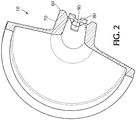
- Luer connection device 10 includes a housing 20 having a side wall 30 with an inside surface defining a lumen 40 with a central axis, a proximal end 50, and a distal end 60 including a male luer tip 70 within the lumen having a passageway therethrough providing fluid communication between the proximal end 50 and the distal end 60 through which fluid, e.g. flush fluid, may be ejected.
- the male luer tip 70 disposed within the lumen at or near the distal end includes a central flow diverter 80 extending outwardly from the central axis to direct fluid flow to a peripheral circumferential dead space located distal to the male luer tip.
- the luer connection device 10 may also include at least one flow expansion channel 90 for increasing mixing and flow through circumferential dead space in the fluid path distal to the male luer tip.
- the flow expanding channel 90 increases mixing and flow through the "dead" space, thereby significantly improving the removal of the blood, medicine and/or other fluids and provide superior flushing.
- flow expansion channel 90 is disposed on the interior surface of the housing lumen 40 and can be round, square, triangular, or a combination thereof, or any other suitable shape.
- the flow expansion channel 90 is shown as a structure that projects outward from the side wall 30 of the housing lumen 40 and reduces the cross-sectional width of the lumen 40.
- the cross-sectional width of the interior surface of the lumen at the flow expansion channel is less than the cross-sectional width of the lumen at the remaining portions.
- the flow expansion channel 90 may be disposed at other locations along the interior surface of the side wall 30.
- the flow expansion channel 90 may include a plurality of outwardly extending projections disposed along the axial length of the housing 20 and may be disposed at pre-defined intervals along the axial length.
- the flow expansion channels also extend longitudinally along the length of the lumen and may be disposed at intervals along the length of the lumen. In one or more embodiments, the flow expansion channels may be tapered.
- the flow expansion channel 90 is configured to extend in a straight taper outwardly from the lumen 40 towards the central axis of the lumen. In one or more embodiments, the flow expansion channel 90 may be configured to extend in a rotational taper outwardly from the central axis of the lumen. In one or more embodiments, the flow expansion channel 90 is located upstream from the flow diverter 80.
- the flow diverter 80 and/or flow expansion channel 90 is located within the interior surface of the lumen 40 forces fluid to peripheral space formed between the male and female luer connections.
- the central flow path diverter alone or in combinations with the flow expansion channels, significantly improves the flushing and removal of fluid downstream from the luer tip by forcing the fluid to the periphery or the female luer space.
- the present invention improves flow based on flow expansion, disruptions of dead space creating features, and flow diversion outward.
- the proximal end 50 of the luer connection device 10 is integrally connected to a vascular access device.
- the vascular access device may be a syringe, extension set, intravenous set, stop cock, tubing, high pressure extension tubing, or needleless access device.
- the luer connection device is removably connected to a vascular access device.
- the central flow path diverter comprises a plurality of vanes.
- a vane can include any number of known internal dividers capable of manipulating the path of a liquid.
- Internal dividers may include louvers or tapered leading and tailing edges.
- the plurality of vaines create turbulence in the flow of flushing fluid to reduce the dead space which might otherwise form on the peripheral surface of the wall portion located between the male luer and female luer connection.
- the plurality of vanes may have a tapered leading edge and tapered tailing edge to minimize drag and reduce resistance.
- the tapered leading edge may be configured to create a smooth entrance of fluid and the tapered tailing edge is configured to create a sharp exit for producing turbulent fluid flow upon exiting the flow diverter.
- the plurality of vanes may be configured to extend straight outwardly from the central axis of the lumen 40 to the side wall 30. In yet another embodiment, the plurality of vanes extend outwardly from the central axis of the lumen in a curved configuration. In one or more embodiments, at least one edge of the plurality of vanes has a ramped angled surface to create a greater angle of incidence.
- the flow expansion channel and flow diverter of the present invention may have a variety of cross sectional geometries including, but not limited to, a cross, rectangle, star, triangle, oval, spiral, twisting or helical formation.
- the present invention is also directed to a luer connection device 10 including a housing 20 having a side wall 30 with an inside surface defining a lumen 40, a proximal end 50 and a distal end 60 including a distal wall with an elongate male luer tip 70 extending in a distal direction therefrom having a passageway therethrough providing fluid communication between the proximal end 50 and the distal end 60; and a flow expansion channel 90 being disposed in the lumen 40 tapering outward from the wall of tubular housing 20 and partially extending along a longitudinal axis from the tip opening toward the base opening for increasing mixing and flow through a circumferential dead space in the fluid path distal to the male luer tip.
- the flow expanding channels increase mixing and flow through the "dead" space, thereby significantly improving the removal of the blood, medicine and/or other fluids and provide superior flushing.
- the proximal end 50 is integrally connected to a vascular access device.
- the vascular access device may be a syringe, extension set, intravenous set, stop cock, tubing, high pressure extension tubing, or needleless access device.
- the syringe is a pre-filled flush syringe.
- the luer connection device 10 of claim is removably connected to a vascular access device.
- the flow expansion channel is configured to extend in a straight taper outwardly from the central axis of the lumen. In yet another embodiment of the present invention, the flow expansion channel may be configured to extend in a rotational taper outwardly from the central axis of the lumen. In another embodiment, the flow expansion channel may be is configured to scallop outwardly from the central axis of the lumen.
- the flow expansion channel is located at the distal end and projects axially in a proximal direction towards the proximal end.
- the luer connection device 10 also includes a flow diverter 80 disposed in the lumen at or near the distal end of the male luer tip 70 to direct the fluid flow to the periphery of a connecting female luer space upon application of force in the distal direction.
- the flow diverter 80 extends beyond the distal end of the housing 20.
- the flow diverter 80 may be connected to the flow expansion channel 90.
- the flow expansion channel 90 may be located upstream from the flow diverter 80.
- the flow diverter 80 directs fluid flow into the flow expansion channel 90.
- the flow expansion channel 90 directs fluid flow into the flow diverter 80.
- the flow diverter may merge into flow expansion channels.
- the male luer tip may include a rotational flow expanding channels and a central, circulating flow diverter.
- Figure 2 illustrates an exemplary luer connection device 10 having a flow expansion channel 90 and flow diverter 80 that are both configured to extend in a straight taper towards the central axis of the lumen.
- the flow expansion channel is configured to extend in a rotational taper towards the central axis of the lumen and flow diverter 80 is configured to extend in a straight taper towards the central axis of the lumen.
- Figure 5 illustrates an exemplary luer connection device 10 having a male luer tip with a rotational flow expansion channels and central flow diverters.
- the flow diverter is configured to extend in a rotational taper towards the central axis of the lumen and flow expansion channel is configured to extend in a straight taper towards the central axis of the lumen.
- Blood-derived debris in the deadspace is dislodged by diverting the fluid flow to the periphery of the connecting female luer space during a flush procedure to increase mixing and turbulence in the dead space created by a male luer tip.
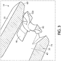
- Figure 3 illustrates an exemplary luer connection device 10 having straight non-rotational flow expansion channels and rotational flow diverter.
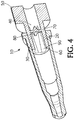
- Figure 4 illustrates an exemplary luer connection device 10 having straight non-rotational flow expanding channels.
- Figure 5 illustrates an exemplary luer connection device 10 having rotational flow expansion channels.
- Figure 6 shows a front view of the flow diverter located at the distal end 60.
- Figure 6 illustrates an exemplary luer connection device 10 having a straight non-rotational flow expansion channels and rotational diverter having ramped angled edges.
- Figure 7 illustrates an exemplary luer connection device 10 having a flow diverter and straight flow expansion channels.
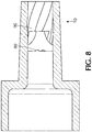
- Figure 8 shows a side view of luer connection device, illustrating how flow expansion channels 90 protrude/ twist as it courses evenly and smoothly from proximal end 50 to distal end 60.
- the purpose of the flow expanding channels is to increase mixing and flow through the "dead" space, thereby significantly improving the removal of the blood, medicine and/or other fluids and provide superior flushing.
- the flow diverter can direct flow into deadspace located between a male and female luer connection so as to minimize the trapping of blood within the passageway.
- Flow diverter 80 is provided within the male luer tip to force the fluid flow to the periphery of the connecting female luer space during a flush procedure to increase mixing and turbulence in the dead space created by a male luer tip between a male and female luer connection. This enhanced flushing results in a reduction in the risk of infection due to residual blood in the catheter system.
- the flow diverter 80 is integrally formed within male luer tip.
- the tip has a flow expanding channel and flow diverter.
- the flow of flushing fluid then circulates radially outward through the flow diverter to the outer periphery of the tip into the deadspace.
- the flush enhancing luer connection device of the present invention provides a significant improvement to the standard flush devices and procedures. This is accomplished by diverting the fluid flow to the periphery of the connecting female luer space during a flush procedure to increase mixing and turbulence in the dead space created by a male luer tip. This enhanced flushing results in a reduction in the risk of infection due to residual blood in the catheter system.
- the dimensions of the luer connection device of the present invention can be made to comply with applicable standards and/or regulations, such as ISO standard 594.
Landscapes
- Health & Medical Sciences (AREA)
- Heart & Thoracic Surgery (AREA)
- Life Sciences & Earth Sciences (AREA)
- Hematology (AREA)
- Anesthesiology (AREA)
- Biomedical Technology (AREA)
- Engineering & Computer Science (AREA)
- Animal Behavior & Ethology (AREA)
- General Health & Medical Sciences (AREA)
- Public Health (AREA)
- Veterinary Medicine (AREA)
- Pulmonology (AREA)
- Vascular Medicine (AREA)
- Biophysics (AREA)
- Infusion, Injection, And Reservoir Apparatuses (AREA)
Applications Claiming Priority (3)
| Application Number | Priority Date | Filing Date | Title |
|---|---|---|---|
| US13/476,357 US9616214B2 (en) | 2012-05-21 | 2012-05-21 | Flush enhancing male luer tip design for syringes and any luer connector |
| EP13731530.5A EP2852431B1 (en) | 2012-05-21 | 2013-05-20 | Flush enhancing male luer tip design for syringes and any luer connector |
| PCT/US2013/041810 WO2013177034A1 (en) | 2012-05-21 | 2013-05-20 | Flush enhancing male luer tip design for syringes and any luer connector |
Related Parent Applications (2)
| Application Number | Title | Priority Date | Filing Date |
|---|---|---|---|
| EP13731530.5A Division EP2852431B1 (en) | 2012-05-21 | 2013-05-20 | Flush enhancing male luer tip design for syringes and any luer connector |
| EP13731530.5A Division-Into EP2852431B1 (en) | 2012-05-21 | 2013-05-20 | Flush enhancing male luer tip design for syringes and any luer connector |
Publications (1)
| Publication Number | Publication Date |
|---|---|
| EP3909637A1 true EP3909637A1 (en) | 2021-11-17 |
Family
ID=48699247
Family Applications (2)
| Application Number | Title | Priority Date | Filing Date |
|---|---|---|---|
| EP21170373.1A Pending EP3909637A1 (en) | 2012-05-21 | 2013-05-20 | Flush enhancing male luer tip design for syringes and any luer connector |
| EP13731530.5A Active EP2852431B1 (en) | 2012-05-21 | 2013-05-20 | Flush enhancing male luer tip design for syringes and any luer connector |
Family Applications After (1)
| Application Number | Title | Priority Date | Filing Date |
|---|---|---|---|
| EP13731530.5A Active EP2852431B1 (en) | 2012-05-21 | 2013-05-20 | Flush enhancing male luer tip design for syringes and any luer connector |
Country Status (11)
| Country | Link |
|---|---|
| US (3) | US9616214B2 (enExample) |
| EP (2) | EP3909637A1 (enExample) |
| JP (2) | JP6282637B2 (enExample) |
| CN (2) | CN104519944B (enExample) |
| AU (2) | AU2013266583B2 (enExample) |
| BR (1) | BR112014029094B1 (enExample) |
| CA (1) | CA2874140C (enExample) |
| ES (1) | ES2879889T3 (enExample) |
| MX (2) | MX351714B (enExample) |
| SG (1) | SG11201407740UA (enExample) |
| WO (1) | WO2013177034A1 (enExample) |
Families Citing this family (14)
| Publication number | Priority date | Publication date | Assignee | Title |
|---|---|---|---|---|
| US8366685B2 (en) | 2011-04-26 | 2013-02-05 | Creative Vascular, Llc | Systems and methods for phlebotomy through a peripheral IV catheter |
| US10076272B2 (en) | 2011-04-26 | 2018-09-18 | Velano Vascular, Inc. | Systems and methods for phlebotomy through a peripheral IV catheter |
| US9295827B2 (en) * | 2013-04-29 | 2016-03-29 | Gale Harrison Thorne | Twisted slit valve |
| EP2952142B1 (en) * | 2014-06-06 | 2017-09-06 | Cook Medical Technologies LLC | Device for forming fistula between blood vessels |
| US11344220B2 (en) | 2016-05-13 | 2022-05-31 | Becton, Dickinson And Company | Invasive medical device cover with magnet |
| US10032552B2 (en) * | 2016-08-30 | 2018-07-24 | Becton, Dickinson And Company | Cover for tissue penetrating device with integrated magnets and magnetic shielding |
| EP3600514B1 (en) | 2017-03-21 | 2022-06-08 | Velano Vascular, Inc. | Systems and methods for controlling catheter device size |
| EP4385409A3 (en) | 2017-03-21 | 2024-09-25 | Velano Vascular, Inc. | Devices for fluid transfer through a placed peripheral intravenous catheter |
| SG11202000493WA (en) * | 2017-08-15 | 2020-02-27 | Becton Dickinson Co | Spinning female luer with threadably removable feature |
| CN116850379A (zh) * | 2018-01-28 | 2023-10-10 | 贝克顿·迪金森公司 | 脉冲式或共振式冲洗注射器 |
| CN109737258A (zh) * | 2019-02-22 | 2019-05-10 | 英诺维尔智能科技(苏州)有限公司 | 一种新型泵液管路接头方式 |
| CN114599419B (zh) | 2019-08-20 | 2024-10-18 | 威蓝诺血管股份有限公司 | 具有延长导管的流体输送装置及其使用方法 |
| MX2023006170A (es) | 2020-11-26 | 2023-06-08 | Avia Vascular Llc | Dispositivos, sistemas y metodos de recoleccion de sangre. |
| EP4422723A4 (en) | 2021-10-29 | 2025-08-27 | Thomas C Kuracina | METHOD AND APPARATUS FOR REDUCING DEAD SPACE IN SMALL CALIBER SYRINGES AND DEVICES |
Citations (7)
| Publication number | Priority date | Publication date | Assignee | Title |
|---|---|---|---|---|
| US4869103A (en) * | 1988-06-03 | 1989-09-26 | Jerman James K | Water flow measuring and dispersing device |
| US5312048A (en) * | 1993-03-25 | 1994-05-17 | Task Force Tips, Inc. | Regulating nozzle with adjustable effective area baffle |
| US5775671A (en) * | 1996-06-13 | 1998-07-07 | Nypro Inc. | Luer-activated valve |
| US20030089797A1 (en) * | 2001-11-14 | 2003-05-15 | Jack Buck | High flow cyclone spa jet |
| US20080287920A1 (en) * | 2007-05-16 | 2008-11-20 | Fangrow Thomas F | Medical connector with closeable male luer |
| US20110160662A1 (en) * | 2009-02-11 | 2011-06-30 | Becton, Dickinson And Company | Systems and methods for providing a flushable catheter assembly |
| US20110276035A1 (en) * | 2010-05-06 | 2011-11-10 | Icu Medical, Inc. | Medical connector with closeable luer connector |
Family Cites Families (10)
| Publication number | Priority date | Publication date | Assignee | Title |
|---|---|---|---|---|
| US5354288A (en) * | 1993-02-24 | 1994-10-11 | Minnesota Mining And Manufacturing Company | Low velocity aortic cannula |
| CA2293583A1 (en) | 1997-06-13 | 1998-12-17 | Micro Therapeutics, Inc. | Contoured syringe and novel luer hub and methods for embolizing blood vessels |
| US6830563B1 (en) | 2001-08-24 | 2004-12-14 | Scott Singer | Syringe tip providing nonlaminar spiral flow and method of use for flushing catheters |
| US20040210202A1 (en) * | 2003-04-17 | 2004-10-21 | Weinstein Gerald S. | Aortic cannula |
| US20070088294A1 (en) | 2005-07-06 | 2007-04-19 | Fangrow Thomas F Jr | Medical connector with closeable male luer |
| US8747387B2 (en) | 2005-10-11 | 2014-06-10 | Covidien Lp | IV catheter with in-line valve and methods related thereto |
| US20070123834A1 (en) | 2005-11-28 | 2007-05-31 | Kimberly-Clark Worldwide, Inc. | Flexible absorbent article |
| US20090143770A1 (en) | 2007-11-30 | 2009-06-04 | Mark Ries Robinson | Medical luer fitting that promotes liquid mixing |
| US8388583B2 (en) | 2009-08-20 | 2013-03-05 | Becton, Dickinson And Company | Systems and methods for providing a flushable catheter assembly |
| BR112013021489B1 (pt) | 2011-02-25 | 2021-02-02 | B. Braun Melsungen Ag | dispositivo médico de lavagem |
-
2012
- 2012-05-21 US US13/476,357 patent/US9616214B2/en active Active
-
2013
- 2013-05-20 JP JP2015514085A patent/JP6282637B2/ja active Active
- 2013-05-20 MX MX2014014131A patent/MX351714B/es active IP Right Grant
- 2013-05-20 EP EP21170373.1A patent/EP3909637A1/en active Pending
- 2013-05-20 SG SG11201407740UA patent/SG11201407740UA/en unknown
- 2013-05-20 AU AU2013266583A patent/AU2013266583B2/en active Active
- 2013-05-20 EP EP13731530.5A patent/EP2852431B1/en active Active
- 2013-05-20 CN CN201380031626.2A patent/CN104519944B/zh active Active
- 2013-05-20 BR BR112014029094-6A patent/BR112014029094B1/pt active IP Right Grant
- 2013-05-20 CA CA2874140A patent/CA2874140C/en active Active
- 2013-05-20 ES ES13731530T patent/ES2879889T3/es active Active
- 2013-05-20 WO PCT/US2013/041810 patent/WO2013177034A1/en not_active Ceased
- 2013-05-21 CN CN201320279892.4U patent/CN203694394U/zh not_active Expired - Lifetime
-
2014
- 2014-11-20 MX MX2022013734A patent/MX2022013734A/es unknown
-
2016
- 2016-12-22 US US15/388,476 patent/US10272237B2/en active Active
-
2017
- 2017-11-14 AU AU2017261469A patent/AU2017261469B2/en active Active
-
2018
- 2018-01-24 JP JP2018009699A patent/JP6850266B2/ja active Active
-
2019
- 2019-04-29 US US16/397,268 patent/US11779745B2/en active Active
Patent Citations (7)
| Publication number | Priority date | Publication date | Assignee | Title |
|---|---|---|---|---|
| US4869103A (en) * | 1988-06-03 | 1989-09-26 | Jerman James K | Water flow measuring and dispersing device |
| US5312048A (en) * | 1993-03-25 | 1994-05-17 | Task Force Tips, Inc. | Regulating nozzle with adjustable effective area baffle |
| US5775671A (en) * | 1996-06-13 | 1998-07-07 | Nypro Inc. | Luer-activated valve |
| US20030089797A1 (en) * | 2001-11-14 | 2003-05-15 | Jack Buck | High flow cyclone spa jet |
| US20080287920A1 (en) * | 2007-05-16 | 2008-11-20 | Fangrow Thomas F | Medical connector with closeable male luer |
| US20110160662A1 (en) * | 2009-02-11 | 2011-06-30 | Becton, Dickinson And Company | Systems and methods for providing a flushable catheter assembly |
| US20110276035A1 (en) * | 2010-05-06 | 2011-11-10 | Icu Medical, Inc. | Medical connector with closeable luer connector |
Also Published As
| Publication number | Publication date |
|---|---|
| CA2874140C (en) | 2020-09-15 |
| US9616214B2 (en) | 2017-04-11 |
| CN104519944B (zh) | 2018-02-06 |
| JP6850266B2 (ja) | 2021-03-31 |
| CN104519944A (zh) | 2015-04-15 |
| AU2013266583B2 (en) | 2017-10-05 |
| BR112014029094A2 (pt) | 2017-06-27 |
| SG11201407740UA (en) | 2014-12-30 |
| BR112014029094B1 (pt) | 2020-09-29 |
| WO2013177034A1 (en) | 2013-11-28 |
| JP2018083104A (ja) | 2018-05-31 |
| US20190247641A1 (en) | 2019-08-15 |
| MX2022013734A (es) | 2022-11-16 |
| ES2879889T3 (es) | 2021-11-23 |
| EP2852431B1 (en) | 2021-06-30 |
| AU2017261469B2 (en) | 2019-04-18 |
| CN203694394U (zh) | 2014-07-09 |
| US10272237B2 (en) | 2019-04-30 |
| CA2874140A1 (en) | 2013-11-28 |
| AU2017261469A1 (en) | 2017-12-07 |
| US11779745B2 (en) | 2023-10-10 |
| JP2015520654A (ja) | 2015-07-23 |
| MX351714B (es) | 2017-10-26 |
| JP6282637B2 (ja) | 2018-02-21 |
| US20240033495A1 (en) | 2024-02-01 |
| MX2014014131A (es) | 2015-06-17 |
| AU2013266583A1 (en) | 2014-12-04 |
| US20130310808A1 (en) | 2013-11-21 |
| EP2852431A1 (en) | 2015-04-01 |
| US20170100576A1 (en) | 2017-04-13 |
Similar Documents
| Publication | Publication Date | Title |
|---|---|---|
| US11779745B2 (en) | Flush enhancing male luer tip design for syringes and any luer connector | |
| CN202724337U (zh) | 具有螺旋缝隙的导管 | |
| US9402975B2 (en) | Systems and methods to increase rigidity and snag-resistance of catheter tip | |
| CN202844307U (zh) | 导管 | |
| EP1905476B1 (en) | Acute hemodialysis catheter assembly | |
| US20160030708A1 (en) | Rifled catheters and vascular access systems | |
| JP4549933B2 (ja) | 血管カテーテル | |
| JP6005643B2 (ja) | 流れ分断機能を有するカテーテルの孔 | |
| JP2012517271A (ja) | 静脈内カニューレ | |
| EP2228091A1 (en) | Double lumen tubing with improved kinking resistance | |
| US12502515B2 (en) | Flush enhancing male luer tip design for syringes and any luer connector | |
| JP5112466B2 (ja) | カテーテルシステム | |
| CN218651934U (zh) | 溶栓导管 | |
| CN115702956A (zh) | 一种引流导管的引流结构及引流导管 |
Legal Events
| Date | Code | Title | Description |
|---|---|---|---|
| PUAI | Public reference made under article 153(3) epc to a published international application that has entered the european phase |
Free format text: ORIGINAL CODE: 0009012 |
|
| STAA | Information on the status of an ep patent application or granted ep patent |
Free format text: STATUS: THE APPLICATION HAS BEEN PUBLISHED |
|
| AC | Divisional application: reference to earlier application |
Ref document number: 2852431 Country of ref document: EP Kind code of ref document: P |
|
| AK | Designated contracting states |
Kind code of ref document: A1 Designated state(s): AL AT BE BG CH CY CZ DE DK EE ES FI FR GB GR HR HU IE IS IT LI LT LU LV MC MK MT NL NO PL PT RO RS SE SI SK SM TR |
|
| B565 | Issuance of search results under rule 164(2) epc |
Effective date: 20211015 |
|
| STAA | Information on the status of an ep patent application or granted ep patent |
Free format text: STATUS: REQUEST FOR EXAMINATION WAS MADE |
|
| 17P | Request for examination filed |
Effective date: 20220511 |
|
| RBV | Designated contracting states (corrected) |
Designated state(s): AL AT BE BG CH CY CZ DE DK EE ES FI FR GB GR HR HU IE IS IT LI LT LU LV MC MK MT NL NO PL PT RO RS SE SI SK SM TR |
|
| STAA | Information on the status of an ep patent application or granted ep patent |
Free format text: STATUS: EXAMINATION IS IN PROGRESS |
|
| 17Q | First examination report despatched |
Effective date: 20241108 |