EP3909530A1 - Embolus removal device with blood flow restriction and related methods - Google Patents
Embolus removal device with blood flow restriction and related methods Download PDFInfo
- Publication number
- EP3909530A1 EP3909530A1 EP21176663.9A EP21176663A EP3909530A1 EP 3909530 A1 EP3909530 A1 EP 3909530A1 EP 21176663 A EP21176663 A EP 21176663A EP 3909530 A1 EP3909530 A1 EP 3909530A1
- Authority
- EP
- European Patent Office
- Prior art keywords
- proximal
- treatment member
- flow restrictor
- expandable treatment
- distal
- Prior art date
- Legal status (The legal status is an assumption and is not a legal conclusion. Google has not performed a legal analysis and makes no representation as to the accuracy of the status listed.)
- Pending
Links
Images


Classifications
-
- A—HUMAN NECESSITIES
- A61—MEDICAL OR VETERINARY SCIENCE; HYGIENE
- A61B—DIAGNOSIS; SURGERY; IDENTIFICATION
- A61B17/00—Surgical instruments, devices or methods, e.g. tourniquets
- A61B17/22—Implements for squeezing-off ulcers or the like on the inside of inner organs of the body; Implements for scraping-out cavities of body organs, e.g. bones; Calculus removers; Calculus smashing apparatus; Apparatus for removing obstructions in blood vessels, not otherwise provided for
- A61B17/221—Gripping devices in the form of loops or baskets for gripping calculi or similar types of obstructions
-
- A—HUMAN NECESSITIES
- A61—MEDICAL OR VETERINARY SCIENCE; HYGIENE
- A61B—DIAGNOSIS; SURGERY; IDENTIFICATION
- A61B17/00—Surgical instruments, devices or methods, e.g. tourniquets
- A61B17/12—Surgical instruments, devices or methods, e.g. tourniquets for ligaturing or otherwise compressing tubular parts of the body, e.g. blood vessels, umbilical cord
- A61B17/12022—Occluding by internal devices, e.g. balloons or releasable wires
- A61B17/12099—Occluding by internal devices, e.g. balloons or releasable wires characterised by the location of the occluder
- A61B17/12109—Occluding by internal devices, e.g. balloons or releasable wires characterised by the location of the occluder in a blood vessel
-
- A—HUMAN NECESSITIES
- A61—MEDICAL OR VETERINARY SCIENCE; HYGIENE
- A61B—DIAGNOSIS; SURGERY; IDENTIFICATION
- A61B17/00—Surgical instruments, devices or methods, e.g. tourniquets
- A61B17/12—Surgical instruments, devices or methods, e.g. tourniquets for ligaturing or otherwise compressing tubular parts of the body, e.g. blood vessels, umbilical cord
- A61B17/12022—Occluding by internal devices, e.g. balloons or releasable wires
- A61B17/12131—Occluding by internal devices, e.g. balloons or releasable wires characterised by the type of occluding device
-
- A—HUMAN NECESSITIES
- A61—MEDICAL OR VETERINARY SCIENCE; HYGIENE
- A61B—DIAGNOSIS; SURGERY; IDENTIFICATION
- A61B90/00—Instruments, implements or accessories specially adapted for surgery or diagnosis and not covered by any of the groups A61B1/00 - A61B50/00, e.g. for luxation treatment or for protecting wound edges
- A61B90/39—Markers, e.g. radio-opaque or breast lesions markers
-
- A—HUMAN NECESSITIES
- A61—MEDICAL OR VETERINARY SCIENCE; HYGIENE
- A61F—FILTERS IMPLANTABLE INTO BLOOD VESSELS; PROSTHESES; DEVICES PROVIDING PATENCY TO, OR PREVENTING COLLAPSING OF, TUBULAR STRUCTURES OF THE BODY, e.g. STENTS; ORTHOPAEDIC, NURSING OR CONTRACEPTIVE DEVICES; FOMENTATION; TREATMENT OR PROTECTION OF EYES OR EARS; BANDAGES, DRESSINGS OR ABSORBENT PADS; FIRST-AID KITS
- A61F2/00—Filters implantable into blood vessels; Prostheses, i.e. artificial substitutes or replacements for parts of the body; Appliances for connecting them with the body; Devices providing patency to, or preventing collapsing of, tubular structures of the body, e.g. stents
- A61F2/01—Filters implantable into blood vessels
- A61F2/013—Distal protection devices, i.e. devices placed distally in combination with another endovascular procedure, e.g. angioplasty or stenting
-
- A—HUMAN NECESSITIES
- A61—MEDICAL OR VETERINARY SCIENCE; HYGIENE
- A61M—DEVICES FOR INTRODUCING MEDIA INTO, OR ONTO, THE BODY; DEVICES FOR TRANSDUCING BODY MEDIA OR FOR TAKING MEDIA FROM THE BODY; DEVICES FOR PRODUCING OR ENDING SLEEP OR STUPOR
- A61M25/00—Catheters; Hollow probes
- A61M25/0021—Catheters; Hollow probes characterised by the form of the tubing
-
- A—HUMAN NECESSITIES
- A61—MEDICAL OR VETERINARY SCIENCE; HYGIENE
- A61B—DIAGNOSIS; SURGERY; IDENTIFICATION
- A61B17/00—Surgical instruments, devices or methods, e.g. tourniquets
- A61B2017/00831—Material properties
- A61B2017/00867—Material properties shape memory effect
-
- A—HUMAN NECESSITIES
- A61—MEDICAL OR VETERINARY SCIENCE; HYGIENE
- A61B—DIAGNOSIS; SURGERY; IDENTIFICATION
- A61B17/00—Surgical instruments, devices or methods, e.g. tourniquets
- A61B2017/00831—Material properties
- A61B2017/00893—Material properties pharmaceutically effective
-
- A—HUMAN NECESSITIES
- A61—MEDICAL OR VETERINARY SCIENCE; HYGIENE
- A61B—DIAGNOSIS; SURGERY; IDENTIFICATION
- A61B17/00—Surgical instruments, devices or methods, e.g. tourniquets
- A61B17/12—Surgical instruments, devices or methods, e.g. tourniquets for ligaturing or otherwise compressing tubular parts of the body, e.g. blood vessels, umbilical cord
- A61B17/12022—Occluding by internal devices, e.g. balloons or releasable wires
- A61B2017/1205—Introduction devices
-
- A—HUMAN NECESSITIES
- A61—MEDICAL OR VETERINARY SCIENCE; HYGIENE
- A61B—DIAGNOSIS; SURGERY; IDENTIFICATION
- A61B17/00—Surgical instruments, devices or methods, e.g. tourniquets
- A61B17/22—Implements for squeezing-off ulcers or the like on the inside of inner organs of the body; Implements for scraping-out cavities of body organs, e.g. bones; Calculus removers; Calculus smashing apparatus; Apparatus for removing obstructions in blood vessels, not otherwise provided for
- A61B2017/22038—Implements for squeezing-off ulcers or the like on the inside of inner organs of the body; Implements for scraping-out cavities of body organs, e.g. bones; Calculus removers; Calculus smashing apparatus; Apparatus for removing obstructions in blood vessels, not otherwise provided for with a guide wire
-
- A—HUMAN NECESSITIES
- A61—MEDICAL OR VETERINARY SCIENCE; HYGIENE
- A61B—DIAGNOSIS; SURGERY; IDENTIFICATION
- A61B17/00—Surgical instruments, devices or methods, e.g. tourniquets
- A61B17/22—Implements for squeezing-off ulcers or the like on the inside of inner organs of the body; Implements for scraping-out cavities of body organs, e.g. bones; Calculus removers; Calculus smashing apparatus; Apparatus for removing obstructions in blood vessels, not otherwise provided for
- A61B2017/22051—Implements for squeezing-off ulcers or the like on the inside of inner organs of the body; Implements for scraping-out cavities of body organs, e.g. bones; Calculus removers; Calculus smashing apparatus; Apparatus for removing obstructions in blood vessels, not otherwise provided for with an inflatable part, e.g. balloon, for positioning, blocking, or immobilisation
-
- A—HUMAN NECESSITIES
- A61—MEDICAL OR VETERINARY SCIENCE; HYGIENE
- A61B—DIAGNOSIS; SURGERY; IDENTIFICATION
- A61B17/00—Surgical instruments, devices or methods, e.g. tourniquets
- A61B17/22—Implements for squeezing-off ulcers or the like on the inside of inner organs of the body; Implements for scraping-out cavities of body organs, e.g. bones; Calculus removers; Calculus smashing apparatus; Apparatus for removing obstructions in blood vessels, not otherwise provided for
- A61B2017/22079—Implements for squeezing-off ulcers or the like on the inside of inner organs of the body; Implements for scraping-out cavities of body organs, e.g. bones; Calculus removers; Calculus smashing apparatus; Apparatus for removing obstructions in blood vessels, not otherwise provided for with suction of debris
-
- A—HUMAN NECESSITIES
- A61—MEDICAL OR VETERINARY SCIENCE; HYGIENE
- A61B—DIAGNOSIS; SURGERY; IDENTIFICATION
- A61B17/00—Surgical instruments, devices or methods, e.g. tourniquets
- A61B17/22—Implements for squeezing-off ulcers or the like on the inside of inner organs of the body; Implements for scraping-out cavities of body organs, e.g. bones; Calculus removers; Calculus smashing apparatus; Apparatus for removing obstructions in blood vessels, not otherwise provided for
- A61B17/221—Gripping devices in the form of loops or baskets for gripping calculi or similar types of obstructions
- A61B2017/2212—Gripping devices in the form of loops or baskets for gripping calculi or similar types of obstructions having a closed distal end, e.g. a loop
-
- A—HUMAN NECESSITIES
- A61—MEDICAL OR VETERINARY SCIENCE; HYGIENE
- A61B—DIAGNOSIS; SURGERY; IDENTIFICATION
- A61B17/00—Surgical instruments, devices or methods, e.g. tourniquets
- A61B17/22—Implements for squeezing-off ulcers or the like on the inside of inner organs of the body; Implements for scraping-out cavities of body organs, e.g. bones; Calculus removers; Calculus smashing apparatus; Apparatus for removing obstructions in blood vessels, not otherwise provided for
- A61B17/221—Gripping devices in the form of loops or baskets for gripping calculi or similar types of obstructions
- A61B2017/2215—Gripping devices in the form of loops or baskets for gripping calculi or similar types of obstructions having an open distal end
-
- A—HUMAN NECESSITIES
- A61—MEDICAL OR VETERINARY SCIENCE; HYGIENE
- A61B—DIAGNOSIS; SURGERY; IDENTIFICATION
- A61B17/00—Surgical instruments, devices or methods, e.g. tourniquets
- A61B17/22—Implements for squeezing-off ulcers or the like on the inside of inner organs of the body; Implements for scraping-out cavities of body organs, e.g. bones; Calculus removers; Calculus smashing apparatus; Apparatus for removing obstructions in blood vessels, not otherwise provided for
- A61B17/221—Gripping devices in the form of loops or baskets for gripping calculi or similar types of obstructions
- A61B2017/2217—Gripping devices in the form of loops or baskets for gripping calculi or similar types of obstructions single wire changing shape to a gripping configuration
-
- A—HUMAN NECESSITIES
- A61—MEDICAL OR VETERINARY SCIENCE; HYGIENE
- A61B—DIAGNOSIS; SURGERY; IDENTIFICATION
- A61B90/00—Instruments, implements or accessories specially adapted for surgery or diagnosis and not covered by any of the groups A61B1/00 - A61B50/00, e.g. for luxation treatment or for protecting wound edges
- A61B90/39—Markers, e.g. radio-opaque or breast lesions markers
- A61B2090/3966—Radiopaque markers visible in an X-ray image
-
- A—HUMAN NECESSITIES
- A61—MEDICAL OR VETERINARY SCIENCE; HYGIENE
- A61F—FILTERS IMPLANTABLE INTO BLOOD VESSELS; PROSTHESES; DEVICES PROVIDING PATENCY TO, OR PREVENTING COLLAPSING OF, TUBULAR STRUCTURES OF THE BODY, e.g. STENTS; ORTHOPAEDIC, NURSING OR CONTRACEPTIVE DEVICES; FOMENTATION; TREATMENT OR PROTECTION OF EYES OR EARS; BANDAGES, DRESSINGS OR ABSORBENT PADS; FIRST-AID KITS
- A61F2/00—Filters implantable into blood vessels; Prostheses, i.e. artificial substitutes or replacements for parts of the body; Appliances for connecting them with the body; Devices providing patency to, or preventing collapsing of, tubular structures of the body, e.g. stents
- A61F2/01—Filters implantable into blood vessels
- A61F2002/016—Filters implantable into blood vessels made from wire-like elements
-
- A—HUMAN NECESSITIES
- A61—MEDICAL OR VETERINARY SCIENCE; HYGIENE
- A61F—FILTERS IMPLANTABLE INTO BLOOD VESSELS; PROSTHESES; DEVICES PROVIDING PATENCY TO, OR PREVENTING COLLAPSING OF, TUBULAR STRUCTURES OF THE BODY, e.g. STENTS; ORTHOPAEDIC, NURSING OR CONTRACEPTIVE DEVICES; FOMENTATION; TREATMENT OR PROTECTION OF EYES OR EARS; BANDAGES, DRESSINGS OR ABSORBENT PADS; FIRST-AID KITS
- A61F2230/00—Geometry of prostheses classified in groups A61F2/00 - A61F2/26 or A61F2/82 or A61F9/00 or A61F11/00 or subgroups thereof
- A61F2230/0063—Three-dimensional shapes
- A61F2230/0067—Three-dimensional shapes conical
-
- A—HUMAN NECESSITIES
- A61—MEDICAL OR VETERINARY SCIENCE; HYGIENE
- A61M—DEVICES FOR INTRODUCING MEDIA INTO, OR ONTO, THE BODY; DEVICES FOR TRANSDUCING BODY MEDIA OR FOR TAKING MEDIA FROM THE BODY; DEVICES FOR PRODUCING OR ENDING SLEEP OR STUPOR
- A61M25/00—Catheters; Hollow probes
- A61M25/0021—Catheters; Hollow probes characterised by the form of the tubing
- A61M2025/0042—Microcatheters, cannula or the like having outside diameters around 1 mm or less
Definitions
- the present invention generally relates to devices and methods useful for clot retrieval, and removal devices to treat, among other things, ischemic stroke.
- IV intravenous
- clot dissolving medicine such as the thrombolytic agent (Tissue Plasminogen Activator (t-PA))
- tissue Plasminogen Activator t-PA
- Intravenous t-PA is currently limited in use because it must be used within a three-hour window from the onset of a stroke and can result in an increased risk of bleeding. This standard of care leaves room for upgrade, and is only the appropriate approach to treatment for a limited class of individuals, groups and temporally-limited exigent cases.
- a second option includes the use of mechanical thrombectomy devices. Such devices are designed to physically capture an embolus or clot, and to remove it from the blocked vessel, thereby restoring blood flow.
- the major advantage of the mechanical thrombectomy device is it can expand the treatment window from three hours to over ten hours.
- Some existing mechanical thrombectomy devices used for increasing blood flow through an obstructed blood vessel include: 1) a filter trap designed and built to collect and remove emboli; 2) a cork-screw guidewire-like device to retrieve embolus; and 3) a stent-like device connected to a delivery wire to retrieve embolus.
- AH of these devices suffer from certain disadvantages.
- filter-type thrombectomy devices tend to be cumbersome and difficult to deliver and deploy, and a larger-profile guide catheter may be needed to fully remove the embolus.
- Cork-screw guidewire devices can only capture and remove emboli that are firm, or subject to certain mechanical variables such as being held together by itself as one piece. Cork-screw guidewire devices are not effective in removing particulate matter that may be scattered or broken up.
- Stent-like mechanical thrombectomy devices are not capable of capturing small emboli that break off from a large embolus (if any), and can lead to complications such as the blockage of distal smaller vessels, vessel dissection, perforation, and hemorrhage arising as a result of over-manipulation in the vessel.
- the device may capture an embolus, but then lose grasp of it and migrate/deposit it incidentally into another area of the neurovasculature, creating the potential for a new stroke in a different part of the neurovasculature: 2) the device is not capable of capturing small embolus breaking off from the larger embolus and preventing it from migrating to a more distal area of the neurovasculature; 3) the relative large device profile prevents these devices from treating the distal smaller diameter vessels; and 4) risk of sICH (symptomatic Intra-cerebral Hemorrhage) after intra-arterial clot removal in acute stroke patients.
- sICH symptomatic Intra-cerebral Hemorrhage
- the present invention is directed to a method and devices for removing clots, emboli and other luminal blockages from a blood vessel.
- a clot removal device having an expandable treatment member having a distal tip and a proximal end, a delivery wire having a distal end coupled to the proximal end of the expandable treatment member, and a flow restrictor carried along the delivery wire at a location that is separate and proximal from the expandable treatment member.
- the flow restrictor has a body with a distal section and a proximal section, the distal section being covered and the proximal section being uncovered.
- An access catheter is delivered to a location proximal to a location of a clot or embolus in a blood vessel, and then the clot removal device is delivered through a lumen in the access catheter to the location of the clot or embolus in the blood vessel.
- the expandable treatment member is expanded at a location that is at or distal to the location of the clot or embolus, and the clot or embolus is caught in. or engaged with, the expandable treatment member.
- the access catheter is then positioned with respect to the flow restrictor such that the uncovered proximal section is completely covered by the distal end of the access catheter and the covered distal section forms a seal with the distal end of the access catheter, and then aspiration is applied through the access catheter and through the uncovered proximal section to remove the clot or embolus from the blood vessel.
- the clot removal device of the present invention can also be used in accordance with another method, where the clot removal device is delivered to a location of a clot or embolus in a blood vessel, the expandable treatment member is expanded at a location that is at or distal to the location of the clot or embolus, the clot or embolus is caught in. or engaged with, the expandable treatment member, the expandable treatment member is withdrawn into the distal section of the flow restrictor, and the expandable treatment member and the flow restrictor are withdrawn from the blood vessel.
- the devices of the present invention can be made from either metallic biocompatible material (such as Nitinol, stainless steel, Co-Cr base alloy, Ta, Ti, etc.) or polymer based biocompatible material (polymers with shape memory effect, PTFE, HDPE, LDPE, Dacron, Polyester, etc.).
- metallic biocompatible material such as Nitinol, stainless steel, Co-Cr base alloy, Ta, Ti, etc.
- polymer based biocompatible material polymers with shape memory effect, PTFE, HDPE, LDPE, Dacron, Polyester, etc.
- the present invention is directed to a device for removing emboli and other luminal blockages.
- the device includes an expandable treatment member, such as a mesh or a cage, that is associated with a proximal flow restrictor.
- the expandable treatment member is positioned within or distal to an embolus within a blood vessel and then transitioned into an expanded state.
- the expandable treatment members normal state is the expanded configuration, and the expandable treatment member is compacted and delivered to the treatment site in the compacted configuration through a delivery sheath or catheter.
- the expandable treatment member is deployed from the delivery sheath, which causes it to return to its normal expanded profile by the elastic energy stored in the device.
- Expansion of the expandable treatment member engages the expandable treatment member with the emboli or clot at the blockage.
- the proximal flow restrictor can also expand to a larger diameter state when it is deployed from the delivery sheath or catheter. Expansion of the proximal flow restrictor advantageously limits or restricts forward blood flow and creates a pressure gradient within the blood vessel between locations distal and proximal to the flow restrictor. The pressure gradient helps to prevent the clots from being flushed away from the treatment member, thereby assisting in removal of the embolus from the blood vessel. Specifically, the pressure difference can act like a vacuum to assist in removal of the embolus from the blood vessel.
- the expandable treatment member and the emboli engaged with the expandable treatment member are removed from the blood vessel.
- the expandable treatment member (with the blood clot engaged) can also be pulled inside the proximal flow restrictor first (i.e.. the clot retrieval component with clots engaged are housed inside proximal restrictor), and then pulled back into guide catheter, and removed from the blood vessel.
- aspiration/vacuum suction can be applied through the lumen of the access catheter lumen and proximal flow restrictor to prevent clots from breaking off and flowing downstream.
- proximal flow restrictor regulates the forward blood flow and allows the controlled (gradual) restoration of the blood flow, and reduces the risk of sICH (symptomatic Intra-cerebral Hemorrhage) after intra-arterial clot removal in acute stroke patients.
- sICH symptomatic Intra-cerebral Hemorrhage
- Devices of the present invention are suitable for removal of blockages in body lumens, and are particularly well-suited for removal of thrombi, emboli, or atheroma in the vasculature, including those in arteries and veins. It is understood that the dimensions of the device may be modified to suit a particular application. For example, devices of the invention used for treatment of deep vein thrombosis may have a larger cross-section than devices of the invention used for treatment of brain ischemia.
- the unique device design included in this invention has the advantage of providing a proximal flow restriction feature to block the forward flow of blood when the device is deployed during use. This feature can help to eliminate or reduce the risk of flush, or the break-up of the blood clots during the procedure.
- Another important advantage provided by the present invention is the central lumen of the proximal flow restrictor can be used or combined with the lumen of the access catheter to apply aspiration/suction force to help with the complete removal of the blood clots in the vasculature.
- the device described in the present invention overcomes the shortcomings of the existing technologies and can be delivered to the target vasculature smoothly, can be retrieved safely, and can remove the entire embolus with fewer passes.
- the mechanical thrombectomy device described in the present invention can be compacted to a low profile and loaded onto a delivery system and delivered to the target location in the vessel by a medical procedure such as through use of a delivery catheter.
- the mechanical thrombectomy device can be released from the delivery system when it reaches the target implant site and expanded to its normal expanded profile by the elastic energy stored in the device (self-expandable device).
- the expandable treatment member in relation to the embolus or blood clot, it can either be deployed at the site of the embolus, or deployed distal to the embolus.
- the expandable treatment member can also be used to remove the embolus from the proximal portion to the distal portion with multiple passes, until the entire embolus is removed.
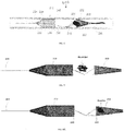
- FIGS. 1 -2 illustrate a device 100 for removing emboli and other luminal blockages according to the present invention.
- the device 100 can be made from one piece or multiple pieces of NitinolTM super elastic material or NitinolTM super-elastic alloy tubing. It can also be made from other biocompatible materials that exhibit super-elastic or shape memory properties.
- the device 100 can be made by laser cutting, mechanical machining, chemical machining, electrochemical machining, EDM, braiding and related techniques known to those skilled in the art.
- the device 100 has an expandable treatment member 102 carried along a delivery wire 104 adjacent the distal end of the delivery wire 104.
- the delivery wire 104 has a soft distal tip 106 that extends distal from the expandable treatment member 102, and has a marker coil embedded therein.
- a plurality of laser cut control arms 08 couple the proximal portion of the expandable treatment member 102 with a hub 1 1 0 along the delivery wire 1 04.
- each control arm 108 has opposite ends connecting the proximal portion of the expandable treatment member 102 and the hub 1 10.
- a proximal flow restrictor 1 12 is carried on the delivery wire 104 proximal to the hub 1 10. Marker bands or marker coils can be incorporated into the proximal flow restrictor 1 12 and the expandable treatment member 1 02 for visibility. At least one end of the proximal flow restrictor 1 12 can move freely along the delivery wire 104.
- the expandable treatment member 102 can be configured to act as a catch basket for the clot or embolus, and in this embodiment is shaped as a cone in its fully expanded configuration, with an apex 120 at the distal-most portion of the expandable treatment member 102 secured to the delivery wire 04 adjacent the distal tip 106, and with the expandable treatment member 102 increasing radially in diameter until reaching its proximal-most ring 122.
- the expandable treatment member 102 can be made of a NtttnolTM braided mesh and can be shape-set to the cone shape by a thermal mechanical process. Most significantly, the expandable treatment member 102 is not cylindrical in configuration which allows it to better conform to the vessel contour and to move more freely inside the vessel.
- the size of the opening for the ring 122 can range from 0.5 mm to 12 mm.
- the length of the distal cone portion from the apex 120 to the ring 122 can range from 2 mm to 40 mm.
- the meshed frame of the expandable treatment member 102 can be provided with a plurality of openings.
- Frame members or struts form the body of the meshed frame and define the plurality of openings.
- the frame members are a plurality of intersecting wires or other threads.
- the frame members may form a mesh or cage-like structure that defines the plurality of openings.
- the expandable treatment member 102 can include a plurality of protrusions 150 on the frame. See FIG. 1 The plurality of protrusions 150 further engages the embolus for removal.
- the expandable treatment member 102 may include one or more surface modifications or treatments.
- the surface of the expandable treatment member 102 may be roughened to improve clot adhesion.
- the main geometrical axis of the expandable treatment member 102 can be offset or different from the longitudinal center axis of the native blood vessel.
- both the delivery catheter (e.g., microcatheter 124) and/or the movement axis of the expandable treatment member 102 can be different from the longitudinal central axis of the vessel, and can contact the side wall of the blood vessel.
- the delivery wire 104 can be made of super-elastic Nitinol wire, stainless steel wire, braided stainless steel wire. Co-Cr alloy and other biocompatible materials.
- the diameter of the delivery wire 104 can range from 0.008" to 0.030", and the delivery wire 104 can have variable diameters/stiffness along its length.
- This distal tip 106 can be made of Ta, Pt, W, Pt-W, or Pt-Ir alloys for radiopacity, and from radiopaque coils or markers.
- the control arms 108 can be laser-cut from a super-elastic Nitinol material. They are preferably taut when the expandable treatment member 102 is in its full expanded configuration.
- the control arms 108 function to control the opening diameter of the ring 122. so that the largest diameter of the ring 122 can be achieved when the control arms 108 are completely pushed out of the sheath of a microcatheter 124 (see FIG. 2 ).
- the diameter of the ring 122 can be adjusted by the length of the control arms 108 being pushed out of the microcatheter 124. Even though the present embodiments are being described as having three control arms 108. it is possible to provide one, or more than two, control arms 108.
- the hub 1 10 can be made from radiopaque materials, and can move freely along, and with respect to, the delivery wire 104.
- the hub 1 10 can also be secured to a fixed location along the delivery wire 104
- the proximal flow restrictor 1 12 can be a bulbous structure and can be made of a NitinolTM mesh, and it is fixedly connected to the delivery wire 104 at its proximal end, while the distal end of the proximal flow restrictor 1 12 can move freely along, and with respect to, the delivery wire 104.
- the proximal flow restrictor 1 12 can be fixedly connected to the delivery wire 104 at its distal end, while the proximal end of the proximal flow restrictor 1 12 can move freely along, and with respect to, the delivery wire 104.
- the proximal flow restrictor 1 12 can have a first smaller compacted profile for delivery through the microcatheter 124 possible.
- the proximal flow restrictor 1 12 can have a second larger expanded diameter/profile when released from the microcatheter 124 or other delivery system to block, limit, or restrict the blood flow.
- the bulbous structure can be a braided or laser cut structure, and made from a film, membrane, braided or netted material.
- the proximal flow restrictor 112 is a polymeric film or membrane.
- the proximal flow restrictor 112 is a braided or woven net formed from a metal, polymer, or combination thereof.
- the type and material of the proximal flow restrictor 212 may be chosen based on the desired coverage (i.e. amount of flow to be restricted).
- the surface of the proximal flow restrictor can be either entirely or partially covered by some polymer materials to restrict the blood flow. It can be fabricated from the one or two element(s) of the device 100, or fabricated from other pieces of material, then attached to the delivery wire 104 by mechanical means, or via a thermal (laser or soldering) process, or adhesive/glue, or heat shrink technology.
- the bulbous structure can also be fabricated from the same piece of NitinolTM tubing as that of the device 100 by laser cutting or chemical processes and then shape-set to a larger diameter than the raw NitinolTM tubing.
- the proximal flow restrictor 112 can have a diameter in its fully expanded configuration that is about the same as the diameter of the opening ring 122 of the expandable treatment member 102 when the expandable treatment member 102 is in its fully expanded configuration.
- the diameter of the proximal flow restrictor 1 12 can range from 0.5 mm to 12 mm, and its length can range from 2 mm to 60 mm.
- Radiopaque markers can be attached on any portion of the device 100 for positioning.
- One way to provide full visibility for the device 100 is to run a radiopaque material through the entire or partial lumen of the delivery wire 104. Markers can also be placed on the expandable treatment member 102 to aid in positioning.
- radiopaque markers (marker coils, marker bands, radiopaque wire(s), radiopaque coatings, etc.) can be integrated into the proximal flow restrictor 112.
- the device 100 can have a surface treatment on selected portions to improve performance for the selected portions of the device 100.
- Both the proximal flow restrictor 112 and the expandable treatment member 102 can either be coated or covered, entirely or partially, by typical biocompatible materials for lubricity.
- the surface of the expandable treatment member 102 can have either a positive or negative charge for improved clot adhesion.
- the surface of the expandable treatment member 102 can also be either mechanically or chemically treated to have a "rough" surface for improved clot adhesion.
- the "rough" surface can be achieved by (i) a porous surface coating or layer (ii) a micro blasted surface or micropinning, or (iii) an irregular strut geometry or arrangement.
- the expandable treatment member 102 can be fully or partially coated with chemical(s), drug(s) or other bioagents to prevent clotting and/or for the better adhesion between the device and embolus.
- the surfaces of the expandable treatment member 102 and the proximal flow restrictor 1 12 can be treated to form different surface layers (e.g., oxidation layer, Nitro or carbonized or N- -C-combined surface layer, etc.) for better adhesion between the expandable treatment member 102 and the embolus.
- FIG. 2 shows the device 100 compressed and fitted inside a microcatheter 124.
- a guide wire can be inserted through the vasculature to the target treatment site, and then the microcatheter 124 is delivered over the guide wire to a target location in a vessel with the device 1 00 housed therein using conventional delivery techniques that are known to those skilled in the art.
- the microcatheter 124 can be inserted over the guide wire first, then the compacted device 100 can be inserted through the inner lumen of the microcatheter 124.
- the distal end of the microcatheter 124 can be positioned proximal to, or inside, or distal to, the clot or embolus at the target location, and there is no need for the microcatheter 124 to traverse the clot or embolus, thereby minimizing the possibility of pushing the clot or embolus downstream in the vessel.
- the microcatheter 124 can then be pulled back (proximally) to expose first the expandable treatment member 102 (see FIG. 3A ), then the control arms 108, and then later on the proximal flow restrictor 1 12. Before the control arms 108 are fully exposed, the expandable treatment member 102 will not reach its full diameter, which makes it possible for the expandable treatment member 102 to not disturb clots before the device 100 reaches its desired position. Instead of pulling back the microcatheter 124.
- the expandable treatment member 102 it is also possible to deploy the expandable treatment member 102 by inserting the device 100 into the microcatheter 124 until the distal tip 106 reaches the distal end of the microcatheter 124, and then holding the proximal end of the microcatheter 124 in a stationary position, pushing the device 100 distally out of the microcatheter 124. Under this alternative, there is no need to withdraw the microcatheter 124, which allows the positioning to be more accurate.
- the expandable treatment member 102 will not fully deploy (i.e. , reach its largest diameter) until the control arms 108 have been completely pushed out of the microcatheter 24. This allows for a gap, volume, or space (see FIG.
- the proximal flow restrictor 1 12 eliminates or reduces the forward blood flow to minimize the risk of poor clot retention and clot dislodgement.
- the expandable treatment member 102 can collect all the clots/emboli to prevent them from flowing downstream.
- the proximal flow restrictor 1 12 also regulates the flow of blood during and immediately after the procedure to eliminate the effect of sICH for a better clinical outcome.
- the proximal flow restrictor can surround (i) an outer surface or diameter of a proximal portion of the expandable treatment member, or (ii) both the inner and outer surfaces or diameters of the proximal portion of the expandable treatment member.
- the proximal flow restrictor can cover a length extending between ('I) a proximal end of the expandable treatment member to about half of the length of the expandable treatment member, or (ii) between a proximal end of the expandable treatment member to about one-quarter of the length of the expandable treatment member.
- FIGS. 4-6 illustrate another embodiment of a device 200 for removing emboli and other luminal blockages.
- the device 200 also has an expandable treatment member 202, a soft distal tip 206 (with marked coil), a delivery wire 204. control arms 208. a hub 210 and a proximal flow restrictor 212 that correspond to the expandable treatment member 102, soft distal tip 106 (with marked coil), delivery wire 104, control arms 108, hub 1 10 and proximal flow restrictor 1 12, respectively, for the first embodiment, except for a few differences.
- the expandable treatment member 202 has a slightly different configuration. Instead of the conical configuration of the expandable treatment member 102. the expandable treatment member 202 has a frusto-conical body 228 where its distal-most end does not terminate in an apex, but has a small distal opening.
- the proximal flow restrictor 212 has a different configuration, having a body that includes a cylindrical distal section 230 and a generally conical (or frusto- conical) proximal section 232 that has a tapering configuration.
- the two sections 230 and 232 combine to define a receiving section.
- the body 228 and the sections 230 and 232 can all be laser cut from the same material (e.g., a NitinolTM tubing or sheet), but the sizes of the cells or openings 234 in the body 228 and the sections 230 and 232 can be varied to vary the flexibility of the different body 228 or sections 230, 232.
- the section 232 can have an annular distal edge 240 that functions as an open mouth.
- the sections 230 and 232 can also have different size/porosity, and can either be covered by a biocompatible polymer or left uncovered. One example is to leave the section 232 uncovered, while covering section 230.
- the uncovered section 232 can be incorporated with other access catheters to facilitate the aspiration/suction function.
- the proximal flow restrictor 1 12 can have a braided configuration.
- the delivery wire 204 can have a deflected section 238 extending distally from the section 230 at an angle with respect to the central longitudinal axis to the hub 210, which is offset from the central longitudinal axis occupied by the delivery wire 204.
- the control arms 208 extend from the hub 210 towards the body 228 at different angles. The different angles allows the expandable treatment member 202 to navigate the vascular anatomy more easily, and also better facilitates the collection of clots and particles by the expandable treatment member 202.
- the different angles for the control arms 208 allow the proximal opening of the expandable treatment member 202 to remain open, and not to collapse, during the procedure. The different angles also makes it easier for the control arms 208 to control the diameter or staged deployment of the expandable treatment member 202 during the procedure.
- the proximal flow restrictor 212 is configured so that it can experience relative movement with respect to the expandable treatment member 202. This is accomplished by not having a fixed connection between the proximal flow restrictor 212 and the delivery wire 204, and by allowing the proximal flow restrictor 212 to slide along the delivery wire 204. In other words, the expandable treatment member 202 can move independent of the proximal flow restrictor 212. This provides a more effective capture and removal of the clot as described below.
- the device 200 is loaded inside a microcatheter 124, which is delivered to a target location in a vessel with the device 200 housed therein using conventional delivery techniques that are known to those skilled in the art.
- the distal end of the microcatheter 124 can again be positioned proximal to, or inside, the clot or embolus at the target location, and there is no need for the microcatheter 124 to traverse the clot or embolus.
- the device 200 can then be pushed distally out of the distal end of the microcatheter 124 to expose first the expandable treatment member 202 and then later on the proximal flow restrictor 212. See FIG. 5 .
- the device 200 is then pulled back or withdrawn so that the expandable treatment member 202 catches the clot. See FIG. 6A .
- the proximal flow restrictor 212 can stay at the same location within the vessel, so that when the annular distal edge 240 of the proximal flow restrictor 212 contacts the annular proximal edge or ring 222 of the body 228, and further proximal pulling of the delivery wire 204 will cause the expandable treatment member 202 to be pulled back into the cylindrical section 230 so that the entire device 200 is removed from the vessel.
- the entire clot or embolus can be retained inside a cage defined by the expandable treatment member 202 and the proximal flow restrictor 212 during removal so as to prevent dislodgement or disengagement of the clot. See FIG. 6B .
- the expanded diameter of the annular proximal edge 222 is preferably slightly smaller than the expanded diameter of the cylindrical section 230 and its annular proximal edge 240 so that the expandable treatment member 202 can be retained inside the cylindrical section 230.
- the delivery wire 204 with a lumen that opens at an opening that is located inside the proximal flow restrictor 212 (see FIGS. 13-14 below), so that suction can be applied from the proximal end of the access guide catheters or microcatheter 124 to pull smaller clots and particles into the proximal flow restrictor 212 using suction force, and then removed from the vessel.
- suction/aspiration action through the lumen of the access devices and the encapsulation of the expandable treatment member 102 (with clot engaged) can happen either simultaneously or in sequence during the procedure.
- FIGS. 7-9 illustrate another embodiment of a device 300 for removing emboli and other luminal blockages.
- the device 300 is similar to the device 200 in that it also has an expandable treatment member 302, a delivery wire 304, a hub 310 and a proximal flow restrictor 312 that correspond to the expandable treatment member 202.
- the expandable treatment member 302 has a different configuration, and can be configured as any of the removal devices disclosed in co-pending United States Publication No. 2015-0150672, filed January 16, 2015 , whose entire disclosure is incorporated by this reference as if set forth fully herein. For this reason, there ae no control wires 108/208.
- proximal flow restrictor 312 can be essentially the same as the proximal flow restrictor 212 in FIGS. 4-6 .
- the hub 310 can function as a marker or stopper.
- the expandable treatment member 302 will start to pull the proximal flow restrictor 312 with it once the hub 310 reaches and engages the proximal end of the inside of the proximal flow restrictor 312.
- the entire (or portion of) expandable treatment member 302 with its collected clot would already be retained inside the proximal flow restrictor 312.
- suction force can be applied from the proximal end of the access guide catheter or microcatheter to help pull all the clots/emboli inside the proximal flow restrictor 312.
- the body of the expandable treatment member 302 and the sections of the proximal flow restrictor 312 can all be laser cut from the same material (e.g., a NitinolTM tubing or sheet), but the sizes of the cells or openings in the expandable treatment member 302 and the proximal flow restrictor 312 can be varied to achieve varying flexibilities.
- the proximal tapered portion on the proximal flow restrictor 312 can be uncovered, while the straight portion of the proximal flow restrictor 312 can be covered, to achieve the desired suction effect and suction control.
- the clot can be caught on the surface of, and between the cell spaces, of the expandable treatment member 302, and the expandable treatment member 302 pulled inside the proximal flow restrictor 312 (see FIGS. 8-9 ) completely before the entire system (microcatheter and device 300) is removed from the blood vessel. Since the proximal flow restrictor 312 has no fixed joint with the delivery wire 304, it can remain in a fixed location with respect to the delivery wire 304 and the expandable treatment member 302 so that the expandable treatment member 302 (with the blood clot engaged thereon) can be pulled inside the proximal flow restrictor 312.
- the expandable treatment member 302 can be pulled into the proximal flow restrictor 312 until the hub 310 (acting as a stopper) contacts the narrowed portion of the proximal section 332 of the proximal flow restrictor 312.
- the proximal portion of the expandable treatment member 302 has a tapered configuration so that it can fit into the narrowed proximal section 332.
- the proximal flow restrictor 312 will move together with the expandable treatment member 302 (and blood clot housed inside) when the delivery wire 304 is pulled out.
- the device 300 can be pulled inside a guide catheter for removal out of the vessel, or can be removed out of the vessel without being pulled inside a guide catheter first. Again, suction force can be applied from the proximal end of the access guide catheter or microcatheter to help pull all the clots/embolus inside the proximal flow restrictor 312.
- FIGS. 10-12 illustrate another embodiment of a device 400 for removing emboli and other luminal blockages.
- the device 400 is similar to the device 100 in that it also has an expandable treatment member 402, a delivery wire 404, distal tip 406 and a proximal flow restrictor 412 that correspond to the expandable treatment member 102.
- the expandable treatment member 402 has a different configuration, and has a distal section 440 that is essentially the same as the conical body of the expandable treatment member 102. However, the expandable treatment member 402 also has a proximal section 442 that is also conically shaped with an apex 444 at its proximal end and with its largest diameter portion coupled to the largest-diameter portion of the distal section 440.
- the double tapered configuration of the expandable treatment member 402 allows its distal end to be softer and less traumatic, and also provides a less stiff proximal end, which together allow for easier navigation of the vessel anatomy.
- the distal expandable treatment portion 402 can be either entirely or partially covered by polymer materials to block the blood flow (flow from distal portion of the vessel to proximal portion of the vessel, so that the aspiration effect from the access catheter and proximal flow restrictor will be more effective).
- proximal flow restrictor 412 can be essentially the same as the proximal flow restrictor 212 in FIGS. 4-6 .
- the body of the expandable treatment member 402 and the sections of the proximal flow restrictor 412 can all be laser cut from the same material (e.g. , a NitinolTM tubing or sheet), but the sizes of the cells or openings in the expandable treatment member 402 and the proximal flow restrictor 412 can be varied to achieve varying flexibilities.
- the clot can be engaged on the outside of the distal section 442 (see FIG. 1 1 ) and the expandable treatment member 402 can be pulled inside the proximal flow restrictor 412 (see FIGS. 1 1 and 12 ) completely before the entire system (microcatheter and device 300) is removed from the blood vessel. Since the proximal flow restrictor 412 has no fixed joint with the delivery wire 404, it can remain in a fixed location with respect to the delivery wire 404 and the expandable treatment member
- the expandable treatment member 402 (with the blood clot engaged on its outer surface) can be pulled inside the proximal flow restrictor 412.
- the aspiration can be applied during the procedure through the lumen of the access catheter or microcatheter and the proximal flow restrictor as well.
- FIGS 13A, 13B , and 13C show some exemplary design configurations for the braided proximal flow restrictor.
- the proximal flow restrictor shown in FIGS. 13A-3C and 14A-14B can be the same the proximal flow restrictor 212, although the principles and concepts embodied in FIGS. 13A-13C and 14A-14B also apply to the other proximal flow restrictors shown and described herein.
- the proximal flow restrictor 212 can have a central lumen 260 at the proximal end 262, a tapering proximal portion 232, and a cylindrical distal portion 230.
- the proximal portion 232 can be uncovered, and the distal portion
- suction can be applied through the central lumen 260 from the access catheters.
- a push wire 264 can be connected to the proximal portion 232 to operate the proximal flow restrictor 212.
- This design can be used or incorporated with other commercially-available clot removal devices, and can also be used or incorporated with an access catheter, guide catheter, DAC, or microcatheter to apply suction during the clot removal procedure.
- a different central lumen structure 260a having a lumen can be connected to the proximal portion 232 to operate the proximal flow restrictor 212.
- This design can be used or incorporated with other commercially-available clot removal devices, and can also be used or incorporated with an access catheter, guide catheter, DAC, or microcatheter to apply suction during the clot removal procedure.
- FIGS. 14A and 14B show an exemplary application of the proximal flow restriction feature.
- the proximal portion 232 can be fully uncovered or partially uncovered, and the distal portion 230 can be covered by biocompatible polymer materials.
- the proximal flow restrictor 212 can be delivered to the target location through a microcatheter or other access catheter 224.
- the proximal central lumen 260 can be used to slide along a guidewire or the push wire 264 of the clot retrieval device. Adjusting the relative position/location of the microcatheter 224 with that of the proximal flow restrictor 212, the proximal flow restrictor 212 can either allow proximal forward flow, or cut off the forward flow.
- the suction effect can be applied through the lumen of the microcatheter 224 for improved clot collection, retention and removal.
- the push wire 264 connected to the proximal flow restrictor 212 is pulled back towards the access catheter or microcatheter 224, and the uncovered proximal portion 232 is completely covered by the distal end of the access catheter or microcatheter 224 with the covered distal portion 230 forming a seal with the distal end of the access catheter or microcatheter 224, the forward flow is totally cut off, and then the aspiration/suction can be applied from the proximal end of the access catheter or microcatheter 224 to help retain and collect clots (as shown in FIG.
- the outer diameter of the access catheter 224 is less than the outer diameter of the fully expanded distal portion 230, but that this seal can still be formed when the proximal end of the distal portion 230 is pulled into the distal opening of the access catheter 224 as the proximal part of the distal portion 230 begins to compress and assume a tapered configuration as the distal portion 230 is pulled into the access catheter 224.
- FIGS. 15A-15C illustrate a different embodiment of the present invention, where the device 200 comprises only the flow restrictor 212 and the push wire 264, and where the expandable treatment member 202 is omitted.
- the distal portion 230 is positioned proximal to the blood clot or embolus, and the relative position/location of the access catheter 224 is adjusted by operating the push wire 264, so that the proximal portion 232 of the flow restrictor is covered by the distal end of the access catheter 224.
- Aspiration is then applied to the lumen of the access catheter 224 to suction or aspirate the blood clot into the distal portion 230 and/or proximal portion 232 (see FIG. 15B ), and then the entire flow restrictor 212 (including the clot inside) is pulled into the access catheter 224 (see FIG. 15C ), and the device 200 is removed out of the blood vessel.
- the aspiration can be applied though the central lumen 260a, instead of through the access catheter 224.
- FIGS. 13C and 15A-15C show that the expandable treatment member 202 can be omitted and the flow restrictor 212 itself can be used to remove blood clots or embolus.
- the structural arrangement of the flow restrictor 212 (uncovered proximal portion 232 and covered distal portion 230) facilitates this type of removal.
Landscapes
- Health & Medical Sciences (AREA)
- Life Sciences & Earth Sciences (AREA)
- Surgery (AREA)
- Veterinary Medicine (AREA)
- Biomedical Technology (AREA)
- Heart & Thoracic Surgery (AREA)
- Animal Behavior & Ethology (AREA)
- General Health & Medical Sciences (AREA)
- Public Health (AREA)
- Engineering & Computer Science (AREA)
- Vascular Medicine (AREA)
- Molecular Biology (AREA)
- Medical Informatics (AREA)
- Nuclear Medicine, Radiotherapy & Molecular Imaging (AREA)
- Reproductive Health (AREA)
- Oral & Maxillofacial Surgery (AREA)
- Orthopedic Medicine & Surgery (AREA)
- Transplantation (AREA)
- Cardiology (AREA)
- Biophysics (AREA)
- Pulmonology (AREA)
- Hematology (AREA)
- Anesthesiology (AREA)
- Pathology (AREA)
- Surgical Instruments (AREA)
Applications Claiming Priority (4)
| Application Number | Priority Date | Filing Date | Title |
|---|---|---|---|
| US201562249249P | 2015-10-31 | 2015-10-31 | |
| US201562251069P | 2015-11-04 | 2015-11-04 | |
| PCT/US2016/057244 WO2017074721A1 (en) | 2015-10-31 | 2016-10-15 | Embolus removal device with blood flow restriction and related methods |
| EP16860505.3A EP3367930B1 (en) | 2015-10-31 | 2016-10-15 | Embolus removal device with blood flow restriction |
Related Parent Applications (1)
| Application Number | Title | Priority Date | Filing Date |
|---|---|---|---|
| EP16860505.3A Division EP3367930B1 (en) | 2015-10-31 | 2016-10-15 | Embolus removal device with blood flow restriction |
Publications (1)
| Publication Number | Publication Date |
|---|---|
| EP3909530A1 true EP3909530A1 (en) | 2021-11-17 |
Family
ID=58630579
Family Applications (2)
| Application Number | Title | Priority Date | Filing Date |
|---|---|---|---|
| EP16860505.3A Active EP3367930B1 (en) | 2015-10-31 | 2016-10-15 | Embolus removal device with blood flow restriction |
| EP21176663.9A Pending EP3909530A1 (en) | 2015-10-31 | 2016-10-15 | Embolus removal device with blood flow restriction and related methods |
Family Applications Before (1)
| Application Number | Title | Priority Date | Filing Date |
|---|---|---|---|
| EP16860505.3A Active EP3367930B1 (en) | 2015-10-31 | 2016-10-15 | Embolus removal device with blood flow restriction |
Country Status (10)
| Country | Link |
|---|---|
| US (5) | US20170119409A1 (es) |
| EP (2) | EP3367930B1 (es) |
| JP (1) | JP6878422B2 (es) |
| KR (1) | KR102571962B1 (es) |
| CN (2) | CN108348267B (es) |
| AU (2) | AU2016344440B2 (es) |
| BR (1) | BR112018008678B1 (es) |
| CA (1) | CA3002804C (es) |
| ES (1) | ES2876274T3 (es) |
| WO (1) | WO2017074721A1 (es) |
Families Citing this family (93)
| Publication number | Priority date | Publication date | Assignee | Title |
|---|---|---|---|---|
| US9402707B2 (en) | 2008-07-22 | 2016-08-02 | Neuravi Limited | Clot capture systems and associated methods |
| ES2683943T3 (es) | 2010-10-22 | 2018-09-28 | Neuravi Limited | Sistema de captura y extirpación de coágulos |
| US11259824B2 (en) | 2011-03-09 | 2022-03-01 | Neuravi Limited | Clot retrieval device for removing occlusive clot from a blood vessel |
| WO2012120490A2 (en) | 2011-03-09 | 2012-09-13 | Neuravi Limited | A clot retrieval device for removing occlusive clot from a blood vessel |
| US8663190B2 (en) | 2011-04-22 | 2014-03-04 | Ablative Solutions, Inc. | Expandable catheter system for peri-ostial injection and muscle and nerve fiber ablation |
| US9237925B2 (en) | 2011-04-22 | 2016-01-19 | Ablative Solutions, Inc. | Expandable catheter system for peri-ostial injection and muscle and nerve fiber ablation |
| US20130053792A1 (en) | 2011-08-24 | 2013-02-28 | Ablative Solutions, Inc. | Expandable catheter system for vessel wall injection and muscle and nerve fiber ablation |
| US9056185B2 (en) | 2011-08-24 | 2015-06-16 | Ablative Solutions, Inc. | Expandable catheter system for fluid injection into and deep to the wall of a blood vessel |
| US11419620B2 (en) | 2012-10-03 | 2022-08-23 | The University Of Toledo | Minimally invasive thrombectomy |
| US9526827B2 (en) | 2012-10-29 | 2016-12-27 | Ablative Solutions, Inc. | Peri-vascular tissue ablation catheter with support structures |
| US10736656B2 (en) | 2012-10-29 | 2020-08-11 | Ablative Solutions | Method for painless renal denervation using a peri-vascular tissue ablation catheter with support structures |
| US10945787B2 (en) | 2012-10-29 | 2021-03-16 | Ablative Solutions, Inc. | Peri-vascular tissue ablation catheters |
| US10881458B2 (en) * | 2012-10-29 | 2021-01-05 | Ablative Solutions, Inc. | Peri-vascular tissue ablation catheters |
| US9433429B2 (en) | 2013-03-14 | 2016-09-06 | Neuravi Limited | Clot retrieval devices |
| PL2967611T3 (pl) | 2013-03-14 | 2019-08-30 | Neuravi Limited | Urządzenie do usuwania ostrych blokad z naczyń krwionośnych |
| CN105208950A (zh) | 2013-03-14 | 2015-12-30 | 尼尔拉维有限公司 | 一种用于从血管去除堵塞凝块的凝块收取装置 |
| US9931046B2 (en) | 2013-10-25 | 2018-04-03 | Ablative Solutions, Inc. | Intravascular catheter with peri-vascular nerve activity sensors |
| US9949652B2 (en) | 2013-10-25 | 2018-04-24 | Ablative Solutions, Inc. | Apparatus for effective ablation and nerve sensing associated with denervation |
| US10517666B2 (en) | 2013-10-25 | 2019-12-31 | Ablative Solutions, Inc. | Apparatus for effective ablation and nerve sensing associated with denervation |
| US10213287B2 (en) | 2014-05-16 | 2019-02-26 | Veosource Sa | Implantable self-cleaning blood filters |
| US10265086B2 (en) | 2014-06-30 | 2019-04-23 | Neuravi Limited | System for removing a clot from a blood vessel |
| US11253278B2 (en) | 2014-11-26 | 2022-02-22 | Neuravi Limited | Clot retrieval system for removing occlusive clot from a blood vessel |
| EP3223723B1 (en) | 2014-11-26 | 2020-01-08 | Neuravi Limited | A clot retrieval device for removing occlusive clot from a blood vessel |
| US10617435B2 (en) | 2014-11-26 | 2020-04-14 | Neuravi Limited | Clot retrieval device for removing clot from a blood vessel |
| US11771446B2 (en) | 2020-10-19 | 2023-10-03 | Anaconda Biomed, S.L. | Thrombectomy system and method of use |
| EP3639768A1 (en) * | 2018-10-16 | 2020-04-22 | Anaconda Biomed, S.L. | A device for extraction of thrombus from a blood vessel and a thrombectomy apparatus |
| ES2577288B8 (es) | 2015-01-13 | 2019-01-10 | Anaconda Biomed S L | Dispositivo para trombectomía |
| EP3419528B1 (en) | 2016-02-24 | 2023-06-07 | Incept, LLC | Enhanced flexibility neurovascular catheter |
| EP3467512A4 (en) | 2016-05-25 | 2020-02-19 | Universal Bio Research Co., Ltd. | SAMPLE PROCESSING AND MEASURING SYSTEM |
| MX2019002565A (es) | 2016-09-06 | 2019-09-18 | Neuravi Ltd | Dispositivo de extracción de coágulos para eliminar coágulos oclusivos de un vaso sanguíneo. |
| JP7264581B2 (ja) | 2017-01-06 | 2023-04-25 | インセプト、リミテッド、ライアビリティ、カンパニー | 動脈瘤治療装置向けの抗血栓性コーティング |
| US11583302B2 (en) * | 2017-03-10 | 2023-02-21 | Shanghai Heartcare Medical Technology Co., Ltd. | Thrombectomy device system |
| US9848906B1 (en) * | 2017-06-20 | 2017-12-26 | Joe Michael Eskridge | Stent retriever having an expandable fragment guard |
| US10575864B2 (en) * | 2017-06-22 | 2020-03-03 | Covidien Lp | Securing element for resheathing an intravascular device and associated systems and methods |
| US20190110804A1 (en) | 2017-10-16 | 2019-04-18 | Michael Bruce Horowitz | Catheter based retrieval device with proximal body having axial freedom of movement |
| US20220104839A1 (en) | 2017-10-16 | 2022-04-07 | Retriever Medical, Inc. | Clot Removal Methods and Devices with Multiple Independently Controllable Elements |
| WO2022082213A1 (en) | 2017-10-16 | 2022-04-21 | Retriever Medical, Inc. | Clot removal methods and devices with multiple independently controllable elements |
| CN115120302A (zh) | 2018-01-30 | 2022-09-30 | 上海沃比医疗科技有限公司 | 血栓捕捉装置及其方法 |
| US11191556B2 (en) | 2018-03-01 | 2021-12-07 | Covidien Lp | Catheter including an expandable member |
| US20190274810A1 (en) * | 2018-03-12 | 2019-09-12 | Neurovasc Technologies, Inc. | Flow protection device for ischemic stroke treatment |
| EP3539486A1 (en) * | 2018-03-13 | 2019-09-18 | The University of Toledo | Minimally invasive thrombectomy |
| US11395665B2 (en) | 2018-05-01 | 2022-07-26 | Incept, Llc | Devices and methods for removing obstructive material, from an intravascular site |
| CN112203593A (zh) | 2018-05-01 | 2021-01-08 | 因赛普特有限责任公司 | 用于从血管内部位去除闭塞性物质的装置和方法 |
| US11517335B2 (en) | 2018-07-06 | 2022-12-06 | Incept, Llc | Sealed neurovascular extendable catheter |
| US11471582B2 (en) | 2018-07-06 | 2022-10-18 | Incept, Llc | Vacuum transfer tool for extendable catheter |
| US10849685B2 (en) | 2018-07-18 | 2020-12-01 | Ablative Solutions, Inc. | Peri-vascular tissue access catheter with locking handle |
| KR20210038910A (ko) * | 2018-07-26 | 2021-04-08 | 라피드 메디칼 리미티드 | 와이어 편조 구성을 구비한 관강내 장치 |
| US10842498B2 (en) | 2018-09-13 | 2020-11-24 | Neuravi Limited | Systems and methods of restoring perfusion to a vessel |
| WO2020060932A1 (en) * | 2018-09-18 | 2020-03-26 | Nanostructures, Inc. | Catheter based methods and devices for obstructive blood flow restriction |
| US11406416B2 (en) | 2018-10-02 | 2022-08-09 | Neuravi Limited | Joint assembly for vasculature obstruction capture device |
| CN111067592B (zh) * | 2018-10-22 | 2021-11-26 | 先健科技(深圳)有限公司 | 取栓装置 |
| US11172946B2 (en) | 2018-10-26 | 2021-11-16 | Progressive NEURO, Inc. | Apparatus, system, and method for vasculature obstruction removal |
| CA3119221A1 (en) | 2018-11-13 | 2020-05-22 | Anaconda Biomed, Sl | A thrombectomy system and methods of extracting a thrombus from a thrombus site in a blood vessel of a patient |
| US11197685B2 (en) | 2018-11-15 | 2021-12-14 | Progressive NEURO, Inc. | Apparatus, system, and method for vasculature obstruction removal |
| US11253279B2 (en) | 2018-11-15 | 2022-02-22 | Progressive NEURO, Inc. | Apparatus, system, and method for vasculature obstruction removal |
| JP2022516963A (ja) | 2019-01-08 | 2022-03-03 | プログレッシブ ニューロ アイエヌシー | 脈管系閉塞物を除去するための装置、システム及び方法 |
| WO2020144071A1 (en) | 2019-01-11 | 2020-07-16 | Anaconda Biomed, Sl | Loading device for loading a medical device into a catheter |
| EP3705066B1 (en) | 2019-03-04 | 2021-12-29 | Neuravi Limited | Actuated clot retrieval catheter |
| JP7144345B2 (ja) * | 2019-03-13 | 2022-09-29 | テルモ株式会社 | 医療器具 |
| US11766539B2 (en) | 2019-03-29 | 2023-09-26 | Incept, Llc | Enhanced flexibility neurovascular catheter |
| WO2021020766A1 (ko) * | 2019-07-29 | 2021-02-04 | 주식회사 엔벤트릭 | 혈전 제거 기기 및 이를 이용하는 혈전 제거 방법 |
| CN113347916A (zh) | 2019-10-15 | 2021-09-03 | 因普瑞缇夫护理公司 | 用于多变量卒中检测的系统和方法 |
| US11712231B2 (en) | 2019-10-29 | 2023-08-01 | Neuravi Limited | Proximal locking assembly design for dual stent mechanical thrombectomy device |
| CN110680459A (zh) * | 2019-11-08 | 2020-01-14 | 刘昌伟 | 应用于动、静脉血栓的取栓装置 |
| US11839725B2 (en) | 2019-11-27 | 2023-12-12 | Neuravi Limited | Clot retrieval device with outer sheath and inner catheter |
| US11779364B2 (en) | 2019-11-27 | 2023-10-10 | Neuravi Limited | Actuated expandable mouth thrombectomy catheter |
| US11517340B2 (en) * | 2019-12-03 | 2022-12-06 | Neuravi Limited | Stentriever devices for removing an occlusive clot from a vessel and methods thereof |
| JP2023507553A (ja) | 2019-12-18 | 2023-02-24 | インパラティブ、ケア、インク. | 静脈血栓塞栓症を治療するための方法及びシステム |
| US11633272B2 (en) | 2019-12-18 | 2023-04-25 | Imperative Care, Inc. | Manually rotatable thrombus engagement tool |
| US11259821B2 (en) | 2019-12-18 | 2022-03-01 | Imperative Care, Inc. | Aspiration system with accelerated response |
| US11944327B2 (en) | 2020-03-05 | 2024-04-02 | Neuravi Limited | Expandable mouth aspirating clot retrieval catheter |
| AU2021235887A1 (en) | 2020-03-10 | 2022-09-08 | Imperative Care, Inc. | Enhanced flexibility neurovascular catheter |
| US11883043B2 (en) | 2020-03-31 | 2024-01-30 | DePuy Synthes Products, Inc. | Catheter funnel extension |
| US11759217B2 (en) | 2020-04-07 | 2023-09-19 | Neuravi Limited | Catheter tubular support |
| US11871946B2 (en) | 2020-04-17 | 2024-01-16 | Neuravi Limited | Clot retrieval device for removing clot from a blood vessel |
| US11730501B2 (en) | 2020-04-17 | 2023-08-22 | Neuravi Limited | Floating clot retrieval device for removing clots from a blood vessel |
| US11717308B2 (en) | 2020-04-17 | 2023-08-08 | Neuravi Limited | Clot retrieval device for removing heterogeneous clots from a blood vessel |
| US11737771B2 (en) | 2020-06-18 | 2023-08-29 | Neuravi Limited | Dual channel thrombectomy device |
| US11937836B2 (en) | 2020-06-22 | 2024-03-26 | Neuravi Limited | Clot retrieval system with expandable clot engaging framework |
| US11395669B2 (en) | 2020-06-23 | 2022-07-26 | Neuravi Limited | Clot retrieval device with flexible collapsible frame |
| US11439418B2 (en) | 2020-06-23 | 2022-09-13 | Neuravi Limited | Clot retrieval device for removing clot from a blood vessel |
| US20220008691A1 (en) * | 2020-07-07 | 2022-01-13 | Covidien Lp | Catheter including surface-treated structural support member |
| US11207497B1 (en) | 2020-08-11 | 2021-12-28 | Imperative Care, Inc. | Catheter with enhanced tensile strength |
| US11864781B2 (en) | 2020-09-23 | 2024-01-09 | Neuravi Limited | Rotating frame thrombectomy device |
| US11937837B2 (en) | 2020-12-29 | 2024-03-26 | Neuravi Limited | Fibrin rich / soft clot mechanical thrombectomy device |
| US11872354B2 (en) | 2021-02-24 | 2024-01-16 | Neuravi Limited | Flexible catheter shaft frame with seam |
| EP4329643A1 (en) | 2021-04-27 | 2024-03-06 | Contego Medical, Inc. | Thrombus aspiration system and methods for controlling blood loss |
| US11974764B2 (en) | 2021-06-04 | 2024-05-07 | Neuravi Limited | Self-orienting rotating stentriever pinching cells |
| CN113598885B (zh) * | 2021-08-16 | 2023-03-14 | 启晨(上海)医疗器械有限公司 | 血栓清除装置 |
| IL285744B2 (en) * | 2021-08-19 | 2023-08-01 | Inretio Ltd | blood clot removal device |
| US11937839B2 (en) | 2021-09-28 | 2024-03-26 | Neuravi Limited | Catheter with electrically actuated expandable mouth |
| US20230132996A1 (en) * | 2021-10-28 | 2023-05-04 | Neuravi Limited | Bevel tip expandable mouth catheter with reinforcing ring |
| CN116965883B (zh) * | 2023-09-20 | 2023-12-26 | 杭州亿科医疗科技有限公司 | 一种分体式取栓装置 |
Citations (7)
| Publication number | Priority date | Publication date | Assignee | Title |
|---|---|---|---|---|
| WO2009126747A1 (en) * | 2008-04-08 | 2009-10-15 | Reverse Medical Corporation | Occlusion device and method of use |
| WO2010014447A2 (en) * | 2008-07-29 | 2010-02-04 | University Of Maryland, Baltimore | Embolectomy stroke device |
| US20110213403A1 (en) * | 2010-02-23 | 2011-09-01 | Maria Aboytes | Devices and methods for vascular recanalization |
| WO2012156924A1 (en) * | 2011-05-17 | 2012-11-22 | Cardioflow Ltd. | Vascular occlusion and aspiration device |
| WO2014008460A2 (en) * | 2012-07-05 | 2014-01-09 | Cognition Medical Corp. | Methods, devices, and systems for postconditioning with clot removal |
| US20150112376A1 (en) * | 2013-10-17 | 2015-04-23 | Covidien Lp | Mechanical thrombectomy with proximal occlusion |
| US20150150672A1 (en) | 2013-02-22 | 2015-06-04 | Jianlu Ma | Embolus removal device with blood flow restriction and related methods |
Family Cites Families (44)
| Publication number | Priority date | Publication date | Assignee | Title |
|---|---|---|---|---|
| US4611594A (en) * | 1984-04-11 | 1986-09-16 | Northwestern University | Medical instrument for containment and removal of calculi |
| US5011488A (en) * | 1988-12-07 | 1991-04-30 | Robert Ginsburg | Thrombus extraction system |
| US5527326A (en) | 1992-12-29 | 1996-06-18 | Thomas J. Fogarty | Vessel deposit shearing apparatus |
| US5846251A (en) * | 1996-07-22 | 1998-12-08 | Hart; Charles C. | Access device with expandable containment member |
| US5972019A (en) | 1996-07-25 | 1999-10-26 | Target Therapeutics, Inc. | Mechanical clot treatment device |
| US5814064A (en) * | 1997-03-06 | 1998-09-29 | Scimed Life Systems, Inc. | Distal protection device |
| US20020169474A1 (en) * | 1999-03-08 | 2002-11-14 | Microvena Corporation | Minimally invasive medical device deployment and retrieval system |
| US20030150821A1 (en) | 1999-07-16 | 2003-08-14 | Bates Mark C. | Emboli filtration system and methods of use |
| US7727243B2 (en) | 2000-06-29 | 2010-06-01 | Concentric Medical., Inc. | Systems, methods and devices for removing obstructions from a blood vessel |
| US6663650B2 (en) * | 2000-06-29 | 2003-12-16 | Concentric Medical, Inc. | Systems, methods and devices for removing obstructions from a blood vessel |
| US20040073243A1 (en) * | 2000-06-29 | 2004-04-15 | Concentric Medical, Inc., A Delaware Corporation | Systems, methods and devices for removing obstructions from a blood vessel |
| US7029488B2 (en) | 2001-08-22 | 2006-04-18 | Gore Enterprise Holdings, Inc. | Mechanical thrombectomy device for use in cerebral vessels |
| US7749243B2 (en) | 2001-10-19 | 2010-07-06 | Boston Scientific Scimed, Inc. | Embolus extractor |
| US20040138692A1 (en) | 2003-01-13 | 2004-07-15 | Scimed Life Systems, Inc. | Embolus extractor |
| US20030187495A1 (en) | 2002-04-01 | 2003-10-02 | Cully Edward H. | Endoluminal devices, embolic filters, methods of manufacture and use |
| EP1607045A4 (en) * | 2003-03-27 | 2011-02-16 | Univ Nihon | WIRE FOR INTRODUCTION TO A BIOLOGICAL CHANNEL |
| DE102005059670A1 (de) * | 2005-12-12 | 2007-06-14 | Phenox Gmbh | Vorrichtung zur Entfernung von Thromben aus Blutgefässen |
| US20080234722A1 (en) | 2006-06-14 | 2008-09-25 | Possis Medical, Inc. | Inferior vena cava filter on guidewire |
| FR2904531B1 (fr) * | 2006-08-02 | 2009-06-12 | Eleph Ent Technology | Sonde de gastrostomie percutanee |
| US20090024157A1 (en) | 2007-07-18 | 2009-01-22 | Abbott Laboratories | Embolic protection device with open cell design |
| US8066757B2 (en) * | 2007-10-17 | 2011-11-29 | Mindframe, Inc. | Blood flow restoration and thrombus management methods |
| US8585713B2 (en) | 2007-10-17 | 2013-11-19 | Covidien Lp | Expandable tip assembly for thrombus management |
| US9220522B2 (en) * | 2007-10-17 | 2015-12-29 | Covidien Lp | Embolus removal systems with baskets |
| US8088140B2 (en) * | 2008-05-19 | 2012-01-03 | Mindframe, Inc. | Blood flow restorative and embolus removal methods |
| US9198687B2 (en) | 2007-10-17 | 2015-12-01 | Covidien Lp | Acute stroke revascularization/recanalization systems processes and products thereby |
| US8926680B2 (en) | 2007-11-12 | 2015-01-06 | Covidien Lp | Aneurysm neck bridging processes with revascularization systems methods and products thereby |
| US8545514B2 (en) | 2008-04-11 | 2013-10-01 | Covidien Lp | Monorail neuro-microcatheter for delivery of medical devices to treat stroke, processes and products thereby |
| US10123803B2 (en) * | 2007-10-17 | 2018-11-13 | Covidien Lp | Methods of managing neurovascular obstructions |
| EP2211972B1 (en) * | 2007-10-26 | 2015-12-23 | Embolitech, LLC | Intravascular guidewire filter system for pulmonary embolism protection and embolism removal or maceration |
| DE102007061238A1 (de) * | 2007-12-19 | 2009-06-25 | Acandis Gmbh & Co. Kg | Vorrichtung zur endovaskulären Behandlung, insbesondere zum Entfernen von Konkrementen aus Körpergefäßen |
| JP5385302B2 (ja) * | 2007-12-26 | 2014-01-08 | ラザラス エフェクト, インコーポレイテッド | 回収システムおよびその使用方法 |
| JP5457373B2 (ja) | 2008-02-22 | 2014-04-02 | コヴィディエン リミテッド パートナーシップ | 血流回復のための装置 |
| US20110202088A1 (en) * | 2008-10-24 | 2011-08-18 | Rapid Medical Ltd. | Embolectomy Device With Optional Vibrator |
| JP5490572B2 (ja) | 2010-03-04 | 2014-05-14 | 株式会社マキタ | 手持ち式切断工具 |
| US11026708B2 (en) * | 2011-07-26 | 2021-06-08 | Thrombx Medical, Inc. | Intravascular thromboembolectomy device and method using the same |
| WO2013071173A1 (en) * | 2011-11-11 | 2013-05-16 | Dacuycuy Nathan John | Devices for removing vessel occlusions |
| US20150265299A1 (en) * | 2012-10-03 | 2015-09-24 | Christopher J. Cooper | Minimally Invasive Thrombectomy |
| US20160256255A9 (en) * | 2013-02-22 | 2016-09-08 | Jianlu Ma | Design and methods for a device with blood flow restriction feature for embolus removal in human vasculature |
| CN105208950A (zh) | 2013-03-14 | 2015-12-30 | 尼尔拉维有限公司 | 一种用于从血管去除堵塞凝块的凝块收取装置 |
| KR102366362B1 (ko) | 2013-03-15 | 2022-02-23 | 테루모 코퍼레이션 | 색전 방지 장치 |
| US9439664B2 (en) * | 2013-05-29 | 2016-09-13 | Thomas A. Sos | Thrombus removal and intravascular distal embolic protection device |
| KR101317434B1 (ko) * | 2013-05-31 | 2013-10-10 | (주) 더아이엔지메디칼 | 혈관 이물질 적출용 카테터 |
| US20140364896A1 (en) * | 2013-06-07 | 2014-12-11 | Abott Cardiovascular Systems, Inc. | Device, system, and method for thrombus retrieval |
| EP3027124B1 (en) | 2013-07-31 | 2022-01-12 | Embolic Acceleration, LLC | Devices for endovascular embolization |
-
2016
- 2016-10-15 US US15/294,709 patent/US20170119409A1/en not_active Abandoned
- 2016-10-15 EP EP16860505.3A patent/EP3367930B1/en active Active
- 2016-10-15 EP EP21176663.9A patent/EP3909530A1/en active Pending
- 2016-10-15 CA CA3002804A patent/CA3002804C/en active Active
- 2016-10-15 CN CN201680064144.0A patent/CN108348267B/zh active Active
- 2016-10-15 JP JP2018522652A patent/JP6878422B2/ja active Active
- 2016-10-15 BR BR112018008678-9A patent/BR112018008678B1/pt active IP Right Grant
- 2016-10-15 US US15/294,708 patent/US20170119408A1/en not_active Abandoned
- 2016-10-15 WO PCT/US2016/057244 patent/WO2017074721A1/en active Application Filing
- 2016-10-15 KR KR1020187015223A patent/KR102571962B1/ko active IP Right Grant
- 2016-10-15 ES ES16860505T patent/ES2876274T3/es active Active
- 2016-10-15 CN CN202210262389.1A patent/CN114711895A/zh active Pending
- 2016-10-15 AU AU2016344440A patent/AU2016344440B2/en active Active
-
2017
- 2017-02-15 US US15/433,455 patent/US10070878B2/en active Active
-
2018
- 2018-09-06 US US16/123,947 patent/US10835271B2/en active Active
-
2020
- 2020-10-25 US US17/079,483 patent/US20210038236A1/en active Pending
-
2021
- 2021-01-29 AU AU2021200553A patent/AU2021200553B2/en active Active
Patent Citations (7)
| Publication number | Priority date | Publication date | Assignee | Title |
|---|---|---|---|---|
| WO2009126747A1 (en) * | 2008-04-08 | 2009-10-15 | Reverse Medical Corporation | Occlusion device and method of use |
| WO2010014447A2 (en) * | 2008-07-29 | 2010-02-04 | University Of Maryland, Baltimore | Embolectomy stroke device |
| US20110213403A1 (en) * | 2010-02-23 | 2011-09-01 | Maria Aboytes | Devices and methods for vascular recanalization |
| WO2012156924A1 (en) * | 2011-05-17 | 2012-11-22 | Cardioflow Ltd. | Vascular occlusion and aspiration device |
| WO2014008460A2 (en) * | 2012-07-05 | 2014-01-09 | Cognition Medical Corp. | Methods, devices, and systems for postconditioning with clot removal |
| US20150150672A1 (en) | 2013-02-22 | 2015-06-04 | Jianlu Ma | Embolus removal device with blood flow restriction and related methods |
| US20150112376A1 (en) * | 2013-10-17 | 2015-04-23 | Covidien Lp | Mechanical thrombectomy with proximal occlusion |
Also Published As
| Publication number | Publication date |
|---|---|
| WO2017074721A1 (en) | 2017-05-04 |
| ES2876274T3 (es) | 2021-11-12 |
| CN108348267B (zh) | 2022-04-08 |
| CN114711895A (zh) | 2022-07-08 |
| BR112018008678B1 (pt) | 2022-11-29 |
| BR112018008678A2 (pt) | 2018-10-30 |
| US20190000490A1 (en) | 2019-01-03 |
| US20170119409A1 (en) | 2017-05-04 |
| US10070878B2 (en) | 2018-09-11 |
| JP6878422B2 (ja) | 2021-05-26 |
| EP3367930A4 (en) | 2019-05-22 |
| JP2019500077A (ja) | 2019-01-10 |
| EP3367930A1 (en) | 2018-09-05 |
| US10835271B2 (en) | 2020-11-17 |
| US20170119408A1 (en) | 2017-05-04 |
| CA3002804C (en) | 2023-12-19 |
| AU2021200553B2 (en) | 2022-03-17 |
| KR102571962B1 (ko) | 2023-08-28 |
| US20210038236A1 (en) | 2021-02-11 |
| EP3367930B1 (en) | 2021-06-02 |
| CA3002804A1 (en) | 2017-05-04 |
| KR20180075643A (ko) | 2018-07-04 |
| AU2016344440B2 (en) | 2020-11-05 |
| AU2021200553A1 (en) | 2021-02-25 |
| AU2016344440A1 (en) | 2018-05-17 |
| CN108348267A (zh) | 2018-07-31 |
| US20180103969A1 (en) | 2018-04-19 |
Similar Documents
| Publication | Publication Date | Title |
|---|---|---|
| AU2021200553B2 (en) | Embolus removal device with blood flow restriction and related methods | |
| US20220022901A1 (en) | Flow protection device for ischemic stroke treatment | |
| US11871947B2 (en) | Clot retrieval device for ischemic stroke treatment |
Legal Events
| Date | Code | Title | Description |
|---|---|---|---|
| PUAI | Public reference made under article 153(3) epc to a published international application that has entered the european phase |
Free format text: ORIGINAL CODE: 0009012 |
|
| STAA | Information on the status of an ep patent application or granted ep patent |
Free format text: STATUS: REQUEST FOR EXAMINATION WAS MADE |
|
| 17P | Request for examination filed |
Effective date: 20210528 |
|
| AC | Divisional application: reference to earlier application |
Ref document number: 3367930 Country of ref document: EP Kind code of ref document: P |
|
| AK | Designated contracting states |
Kind code of ref document: A1 Designated state(s): AL AT BE BG CH CY CZ DE DK EE ES FI FR GB GR HR HU IE IS IT LI LT LU LV MC MK MT NL NO PL PT RO RS SE SI SK SM TR |
|
| B565 | Issuance of search results under rule 164(2) epc |
Effective date: 20210921 |