EP3908784B1 - Neigbares leuchtengelenk - Google Patents
Neigbares leuchtengelenk Download PDFInfo
- Publication number
- EP3908784B1 EP3908784B1 EP20700556.2A EP20700556A EP3908784B1 EP 3908784 B1 EP3908784 B1 EP 3908784B1 EP 20700556 A EP20700556 A EP 20700556A EP 3908784 B1 EP3908784 B1 EP 3908784B1
- Authority
- EP
- European Patent Office
- Prior art keywords
- joint
- joint portion
- tiltable
- luminaire
- interengaging surfaces
- Prior art date
- Legal status (The legal status is an assumption and is not a legal conclusion. Google has not performed a legal analysis and makes no representation as to the accuracy of the status listed.)
- Active
Links
Images




Classifications
-
- F—MECHANICAL ENGINEERING; LIGHTING; HEATING; WEAPONS; BLASTING
- F21—LIGHTING
- F21V—FUNCTIONAL FEATURES OR DETAILS OF LIGHTING DEVICES OR SYSTEMS THEREOF; STRUCTURAL COMBINATIONS OF LIGHTING DEVICES WITH OTHER ARTICLES, NOT OTHERWISE PROVIDED FOR
- F21V21/00—Supporting, suspending, or attaching arrangements for lighting devices; Hand grips
- F21V21/14—Adjustable mountings
- F21V21/30—Pivoted housings or frames
-
- F—MECHANICAL ENGINEERING; LIGHTING; HEATING; WEAPONS; BLASTING
- F21—LIGHTING
- F21V—FUNCTIONAL FEATURES OR DETAILS OF LIGHTING DEVICES OR SYSTEMS THEREOF; STRUCTURAL COMBINATIONS OF LIGHTING DEVICES WITH OTHER ARTICLES, NOT OTHERWISE PROVIDED FOR
- F21V21/00—Supporting, suspending, or attaching arrangements for lighting devices; Hand grips
- F21V21/10—Pendants, arms, or standards; Fixing lighting devices to pendants, arms, or standards
- F21V21/116—Fixing lighting devices to arms or standards
-
- F—MECHANICAL ENGINEERING; LIGHTING; HEATING; WEAPONS; BLASTING
- F16—ENGINEERING ELEMENTS AND UNITS; GENERAL MEASURES FOR PRODUCING AND MAINTAINING EFFECTIVE FUNCTIONING OF MACHINES OR INSTALLATIONS; THERMAL INSULATION IN GENERAL
- F16C—SHAFTS; FLEXIBLE SHAFTS; ELEMENTS OR CRANKSHAFT MECHANISMS; ROTARY BODIES OTHER THAN GEARING ELEMENTS; BEARINGS
- F16C11/00—Pivots; Pivotal connections
- F16C11/04—Pivotal connections
-
- F—MECHANICAL ENGINEERING; LIGHTING; HEATING; WEAPONS; BLASTING
- F16—ENGINEERING ELEMENTS AND UNITS; GENERAL MEASURES FOR PRODUCING AND MAINTAINING EFFECTIVE FUNCTIONING OF MACHINES OR INSTALLATIONS; THERMAL INSULATION IN GENERAL
- F16C—SHAFTS; FLEXIBLE SHAFTS; ELEMENTS OR CRANKSHAFT MECHANISMS; ROTARY BODIES OTHER THAN GEARING ELEMENTS; BEARINGS
- F16C11/00—Pivots; Pivotal connections
- F16C11/04—Pivotal connections
- F16C11/10—Arrangements for locking
- F16C11/103—Arrangements for locking frictionally clamped
-
- F—MECHANICAL ENGINEERING; LIGHTING; HEATING; WEAPONS; BLASTING
- F16—ENGINEERING ELEMENTS AND UNITS; GENERAL MEASURES FOR PRODUCING AND MAINTAINING EFFECTIVE FUNCTIONING OF MACHINES OR INSTALLATIONS; THERMAL INSULATION IN GENERAL
- F16M—FRAMES, CASINGS OR BEDS OF ENGINES, MACHINES OR APPARATUS, NOT SPECIFIC TO ENGINES, MACHINES OR APPARATUS PROVIDED FOR ELSEWHERE; STANDS; SUPPORTS
- F16M11/00—Stands or trestles as supports for apparatus or articles placed thereon ; Stands for scientific apparatus such as gravitational force meters
- F16M11/02—Heads
- F16M11/04—Means for attachment of apparatus; Means allowing adjustment of the apparatus relatively to the stand
- F16M11/06—Means for attachment of apparatus; Means allowing adjustment of the apparatus relatively to the stand allowing pivoting
- F16M11/10—Means for attachment of apparatus; Means allowing adjustment of the apparatus relatively to the stand allowing pivoting around a horizontal axis
-
- F—MECHANICAL ENGINEERING; LIGHTING; HEATING; WEAPONS; BLASTING
- F16—ENGINEERING ELEMENTS AND UNITS; GENERAL MEASURES FOR PRODUCING AND MAINTAINING EFFECTIVE FUNCTIONING OF MACHINES OR INSTALLATIONS; THERMAL INSULATION IN GENERAL
- F16M—FRAMES, CASINGS OR BEDS OF ENGINES, MACHINES OR APPARATUS, NOT SPECIFIC TO ENGINES, MACHINES OR APPARATUS PROVIDED FOR ELSEWHERE; STANDS; SUPPORTS
- F16M13/00—Other supports for positioning apparatus or articles; Means for steadying hand-held apparatus or articles
- F16M13/02—Other supports for positioning apparatus or articles; Means for steadying hand-held apparatus or articles for supporting on, or attaching to, an object, e.g. tree, gate, window-frame, cycle
- F16M13/022—Other supports for positioning apparatus or articles; Means for steadying hand-held apparatus or articles for supporting on, or attaching to, an object, e.g. tree, gate, window-frame, cycle repositionable
-
- F—MECHANICAL ENGINEERING; LIGHTING; HEATING; WEAPONS; BLASTING
- F21—LIGHTING
- F21S—NON-PORTABLE LIGHTING DEVICES; SYSTEMS THEREOF; VEHICLE LIGHTING DEVICES SPECIALLY ADAPTED FOR VEHICLE EXTERIORS
- F21S8/00—Lighting devices intended for fixed installation
- F21S8/08—Lighting devices intended for fixed installation with a standard
- F21S8/085—Lighting devices intended for fixed installation with a standard of high-built type, e.g. street light
-
- F—MECHANICAL ENGINEERING; LIGHTING; HEATING; WEAPONS; BLASTING
- F16—ENGINEERING ELEMENTS AND UNITS; GENERAL MEASURES FOR PRODUCING AND MAINTAINING EFFECTIVE FUNCTIONING OF MACHINES OR INSTALLATIONS; THERMAL INSULATION IN GENERAL
- F16C—SHAFTS; FLEXIBLE SHAFTS; ELEMENTS OR CRANKSHAFT MECHANISMS; ROTARY BODIES OTHER THAN GEARING ELEMENTS; BEARINGS
- F16C2362/00—Apparatus for lighting or heating
-
- F—MECHANICAL ENGINEERING; LIGHTING; HEATING; WEAPONS; BLASTING
- F21—LIGHTING
- F21S—NON-PORTABLE LIGHTING DEVICES; SYSTEMS THEREOF; VEHICLE LIGHTING DEVICES SPECIALLY ADAPTED FOR VEHICLE EXTERIORS
- F21S8/00—Lighting devices intended for fixed installation
- F21S8/08—Lighting devices intended for fixed installation with a standard
- F21S8/085—Lighting devices intended for fixed installation with a standard of high-built type, e.g. street light
- F21S8/086—Lighting devices intended for fixed installation with a standard of high-built type, e.g. street light with lighting device attached sideways of the standard, e.g. for roads and highways
-
- F—MECHANICAL ENGINEERING; LIGHTING; HEATING; WEAPONS; BLASTING
- F21—LIGHTING
- F21W—INDEXING SCHEME ASSOCIATED WITH SUBCLASSES F21K, F21L, F21S and F21V, RELATING TO USES OR APPLICATIONS OF LIGHTING DEVICES OR SYSTEMS
- F21W2131/00—Use or application of lighting devices or systems not provided for in codes F21W2102/00-F21W2121/00
- F21W2131/10—Outdoor lighting
- F21W2131/103—Outdoor lighting of streets or roads
Definitions
- the present invention relates to joints for luminaires.
- Particular embodiments of the invention relate to a luminaire joint which is tiltable.
- lighting apparatuses are used to illuminate areas presenting various characteristics. Depending on these characteristics the lighting apparatus will be chosen and adjusted to obtain a desired lighting pattern on the ground to be illuminated.
- One of the important characteristics of the lighting apparatus will be its application, e . g . pedestrian road, highway, one-way road, etc.
- Another important characteristic is the support the lighting apparatus will be attached to. Indeed the type of support, its height, and its position with respect to the surface to be illuminated, will directly influence the lighting pattern obtained.
- joints linking lighting apparatuses, e . g . luminaire heads, and supports corresponding to all these situations would be costly, time consuming, and would require extensive stock keeping. It would therefore be advantageous to be able to design a joint for luminaire with a more adaptive approach whose relative positioning of the lighting apparatus with respect to the support can be modified, on site and/or at the factory, depending on the application and the desired light distribution.
- the object of embodiments of the invention is to provide a luminaire joint which can provide a precise positioning with a reliable adjustment of its mechanism, such that a lighting apparatus provided to the luminaire joint is more adaptable to a site to be illuminated and/or to a specific application. More in particular, embodiments of the invention aim to provide a luminaire joint whose positioning can have a variable angle through a stable mechanism.
- a tiltable joint for a luminaire comprising:
- a common solution to adjust the angular positioning of a luminaire joint is to directly fasten together the engaging elements responsible for the adjustment.
- it creates constraints in the design of the joint which are not circumvented without drawbacks such as poor accuracy of the positioning, or limited range of adjustment between the support and the lighting apparatus. This problem is overcome by a tiltable joint for luminaire as defined above.
- the first and second joint portions are designed such that the second joint portion partially houses the first joint portion. Having a partial housing for the joint increases the protection of the adjustment mechanism. Not only the adjustment mechanism will have additional protection, but the complementary areas of the first joint portion and the overlying second joint portion will be suitable for implementing contact surfaces between the joint portions. This available contact area may be used to design a sizable set of interengaging surfaces, which provides mechanical stability and a broad adjustment range. Moreover the overall cylindrical shapes of the joint portions are well adapted to a rotation of the first joint portion within the second joint portion for an uncomplicated tilt of the joint.
- the first and second joint portions are joined or released from each other through the action of a first and second shaft portions and fixation means.
- the first and second shaft portions extending in alignment with the longitudinal axis of the first joint portion serve as a support for the fixation means which is fastened to the second joint portion. Due to the coaxial design of the cylindrical shapes of the first and second joint portions, the engaging force exerted by the combined use of the first and second shaft portions and the fixation means is directed towards the central axis of the cylindrical shapes. The engaging force, thus, reliably engages the second joint portion to the first joint portion for a stable positioning.
- Preferred embodiments relate to a tiltable joint for an outdoor luminaire.
- outdoor luminaire it is meant luminaires which are installed on roads, tunnels, industrial plants, stadiums, airports, harbors, rail stations, campuses, parks, cycle paths, pedestrian paths, or in pedestrian zones for example, and which can be used notably for the lighting of an outdoor area, such as roads and residential areas in the public domain, private parking areas and access roads to private building infrastructures, etc.
- a shaft comprises the first and second shaft portions, or a first and second shafts comprise the first and second shaft portions, respectively.
- first and second shaft portions are linked in one piece extending at least between the pair of axially-aligned bearing, optionally extending between the pair of axially-aligned receiving surfaces.
- first and second shafts portions may be comprised by two shafts to be more adaptable.
- the first and second pluralities of interengaging surfaces are a first and second pluralities of interengaging teeth.
- the first and second pluralities of interengaging teeth extend along the main axis of the joint member and of the joint housing, which forces the alignment during the engagement.
- the extent of the plurality of interengaging teeth, their contact surfaces, and the adjustment precision of the first joint portion with respect to the second joint portion can be conveniently customized through the design of the teeth.
- the first and second pluralities of interengaging surfaces may be interengaging conical elements perpendicular to the cylindrical surfaces, rough surfaces configured for producing a predetermined friction when engaged, three-dimensional elements, and the like.
- the angular adjustment has a different precision. It may be an adjustment in steps, or step-less, preferably an adjustment in 5°-steps, more preferably an adjustment in 2,5°-steps.
- the second joint portion is configured for being positioned in a first position of a plurality of positions with respect to the first joint portion, wherein the fixation means is configured for being unfastened to allow the second joint portion to be positioned from the first position to a second position of the plurality of positions with respect to the first joint portion, and wherein the fixation means is further configured for being fastened to prevent a movement of the second joint portion from the second position of the plurality of positions with respect to the first joint portion.
- the release of the fixation means allows the rotation of the second joint portion with respect to the first joint portion for repositioning the tiltable luminaire joint.
- the fixation means inhibits a radial movement of the second joint portion with respect to the first joint portion when fastened. Unfastening the fixation means may be achieved such that the first and second joint portions are still attached while their respective interengaging surfaces are freed from contact. Since the first and/or second shaft portion is able to rotate freely with respect to the first joint portion, the second joint portion may be positioned from a first to a second position of a plurality of positions without having to detach the first and second joint portions.
- the interengaging surfaces may be defined as a plurality of surfaces having different angular positioning with respect to each other and conceived to cooperate with another corresponding plurality of surfaces.
- the interengaging surfaces may comprise straight and/or curved surfaces and have a desired roughness. They may be integrally formed with the first and second joint portions or fixed to them, and be made of e.g. metal or plastic, preferably in metal, more preferably in aluminum.
- the joint is mounted to a support and provided with a luminaire head and gravity maintains the engagement of the interengaging surfaces of the first and second joint portions when unfastening the fixation means.
- the luminaire head may be lifted by an operator to enable the repositioning of the second joint portion with respect to the first joint portion.
- the fixation means extends radially with respect to the pivot axis defined by the first and second shaft portions and is configured for fixing the first and second shaft portions.
- the fixation means extends through the first and second shaft portions.
- the engaging force exerted by the combined use of the first and second shaft portions and the fixation means is substantially perpendicular to the central axis of the cylindrical surfaces of the first and second joint portions. It decreases the risk of slippage between the first and second joint portions when engaged since scissoring forces are minimized.
- the first and/or second shaft portion comprises a landing opposite the axially-aligned receiving surface
- the fixation means is further configured for enabling the engagement by bringing the landing closer to the receiving surface
- the fixation means has a flat support in a plane substantially parallel to the shaft axis upon which it can exert a force. Due to the orientation of the landing, a radial force may be more efficiently applied with respect to the pair of axially-aligned receiving surfaces.
- the first and second shaft portions may both comprise a landing such that the engaging force is applied uniformly on either side of the first and second joint portions.
- the axial shaft may be rotated such that each landing has a fixed orientation with respect to the second joint portion.
- the pair of axially-aligned receiving surfaces enhances the position of the second joint portion with respect to the first and second shaft portions to improve the alignment of the first and second joint portions. An accurate coaxial alignment improves the precision of the joint positioning and the efficiency of the engaging force.
- the fixation means comprises at least one bolt configured for being provided through an aperture of the first and/or second shaft portions, and configured for being fastened to the joint housing of the second joint portion.
- the aperture in the first or second shaft portion forms a guide for the bolt and will be coaxial with the engaging force direction.
- the aperture may be perpendicular to the axis of the shaft portion.
- the bolt head may be supported by the at least one landing.
- the bolt may be fastened to an integral nut portion comprised in the joint housing or to a nut provided to a supporting surface of the joint housing opposite the shaft portion.
- the bolt is being provided through an aperture of the joint housing and is configured for being fastened to a nut integrally formed to the shaft portion or to a nut supported by the shaft portion.
- the bolt is a stud bolt fastened to nuts on either side.
- the engagement of the at least portion of the first plurality of interengaging surfaces and the at least portion of the second plurality of interengaging surfaces is enabled over at least a 90°-arc, preferably over at least a 180°-arc, more preferably over at least a 300°-arc, most preferably over at least a 140°-arc, of the inner cylindrical surface of the second joint portion.
- the tiltable joint 1000 may be configured for being adjusted from -10° to 120°, preferably from -10° to 30°, in a post-top configuration of the luminaire head, and for being adjusted from -100° to 30°, preferably from -30° to 30°, in a side-entry configuration of the luminaire head.
- the luminaire joint is adaptable to a wide angular range.
- the angular range of the interengaging surfaces is smaller on the first joint portion than on the second joint portion.
- the angular range of the interengaging surfaces is larger on the first joint portion than on the second joint portion.
- the angular range of the interengaging surfaces is substantially equal on the first and second joint portions.
- the increased amount of interengaging surfaces in contact may improve the mechanical stability of the joint positioning.
- the interengaging surfaces may be provided over one area, preferably centrally positioned, of the first and second joint portions. Alternatively, the interengaging surfaces may be provided to two or more areas of the first and second joint portions.
- the interengaging surfaces may be provided over a first and second areas, said first area enabling positioning of the second joint portion with respect to the first joint portion over a first sub-range of the total positioning angular range, and said second area enabling positioning over a complementing second sub-range of the total positioning angular range, optionally overlapping the range of the first sub-range.
- the tiltable joint further comprises an angular indicator on at least one of the first joint portion, the second joint portion, or the first and/or second shaft portion.
- the joint may be reliably and precisely arranged in an adequate position of the plurality of positions in order to obtain a desired angular orientation of the associated luminaire head.
- the angular indicator may comprise letters, numbers, and/or a scale associated with the plurality of predetermined positions.
- the tiltable joint may comprise a first angular indicator configured for indicating an angular positioning in a post-top configuration of the luminaire head, and a second angular indicator configured for indicating an angular positioning in a side-entry configuration of the luminaire head.
- one of the first or second plurality of interengaging surfaces extends over an angular arc larger than the other one of the first or second plurality of interengaging surfaces.
- one of the first or second plurality of interengaging surfaces provides for the entire angular range of positions and the other one of the first or second plurality of interengaging surfaces may be designed to achieve an adequate mechanically stable engagement of the first and second joint portions.
- the angular range of positions is maximized on one of the first or second joint portion while reducing the area provided with interengaging surfaces on the other one of the first or second joint portion. Space may be saved which increases the compactness of the tiltable joint.
- the first plurality of interengaging surfaces extends along at least two parallel rows of interengaging surfaces
- the second plurality of interengaging surfaces extends along at least two corresponding parallel rows of interengaging surfaces
- the positioning of the second joint portion with respect to the first joint portion may be spread more evenly over the width of the joint member and joint housing as seen along their main axis direction.
- the two parallel rows are located substantially on the end portions of the joint member and joint housing.
- the spread of interengaging surfaces along two rows may free space in the central portions of the first and second joint portions for additional functionalities, e.g. a passage for electrical connection.
- the first joint portion further comprises a mounting structure configured for mounting the first joint portion to a base support.
- the mounted first joint portion has a fixed angle with respect to the base support and the joint can connect the luminaire head, mounted to the second joint portion, and the base support, thereby forming a luminaire.
- the second joint portion is integrally formed as part of a housing of the luminaire head.
- the first and second joint portions may be utilized interchangeably and that the second joint portion may comprise the mounting structure for mounting the second joint portion to the base support.
- the tiltable joint further comprises a passage for a connecting means between the first joint portion and the second joint portion.
- the connecting means may be wired through the joint.
- the wiring is generally passing through a central cavity of the base support.
- the passage allows maintaining the wiring within a protected enclosure to be connected to the luminaire head.
- the passage is preferably located in a central portion of the first joint portion such that it is protected by the overlying joint housing of the second joint portion.
- the outer cylindrical surface section of the first joint portion is provided with an opening creating said passage.
- the tiltable joint is adapted for maintaining the connection of the connecting means.
- the opening may be positioned such that it is covered by the joint housing of the second joint portion in the plurality of positions.
- the opening may extend in a direction perpendicular to the axis of the cylindrical surface of the joint member to accommodate for the movement of the connecting means across the range of plurality of positions.
- the extent of the connecting means may be adapted to enable for its travel from the closest position of the luminaire head from the opening when attached to the joint, to its furthest position.
- the tiltable joint further comprises another fixations means configured for fixing the second joint portion to the first joint portion.
- the second joint portion may be further secured with respect to the first joint portion which improves the strength of the mechanical link between the first and second joint portions.
- the another fixation means e . g . screw, bolt, rope, may be configured for being fastened to the first joint portion from outside the tiltable joint to enhance the safety of the engagement and against risk of slippage.
- the luminaire system assembly comprises:
- the tiltable joint may be connected to a base support such as a luminaire pole to form a luminaire.
- the tiltable joint may be utilized to orient the luminaire head with respect to the base support to achieve an appropriate lighting pattern on a surface to be illuminated. Typical examples of luminaires are street lights.
- the base support may be connected to a wall or another surface, e.g. for illuminating buildings or tunnels.
- Part of the tiltable joint may be included in a housing of the luminaire head or may be connected to the luminaire head in any manner known to the skilled person.
- the part of the tiltable joint connected to the luminaire head may be interchangeably the first joint portion or the second joint portion, preferably the second joint portion.
- the base support comprises a support pole.
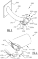
- FIG. 1 shows a perspective view of an exemplary embodiment of a tiltable joint for a luminaire according to the present invention.
- the tiltable joint for a luminaire comprises a first joint portion 100, a second joint portion 200, a first and second shaft portions 300a, 300b, and a fixation means 400.
- Part of the tiltable joint 1000 of Fig.1 may be included in a housing of a luminaire head or may be connected to the luminaire head in any manner known to the skilled person.
- the part of the tiltable joint 1000 connected to the luminaire head may be interchangeably the first joint portion 100 or the second joint portion 200, preferably the second joint portion 200.
- the tiltable joint 1000 may be connected to a base support such as a luminaire pole to form a luminaire. Typical examples of luminaires are street lights or sport lights.
- the tiltable joint 1000 may be connected to a wall or another surface, e.g. for illuminating buildings or tunnels.
- the first joint portion 100 comprises a joint member 110 provided with an outer cylindrical surface section having an axis of rotation PA and opposing bearings 112a, 112b aligned with said axis PA.
- the joint member 110 may be connected to a connecting member 140 extending in a direction CA substantially perpendicular to the axis PA of the joint member 110.
- the connecting member 140 may be configured for being connected to a base support, e.g. a luminaire pole.
- the connecting member 120 has a tubular shape to be connected to a luminaire pole.
- the connecting member 140 may have an inner diameter larger than an outer diameter of the luminaire pole extremity to be mounted over it, or may have an outer diameter smaller than an inner diameter of the luminaire pole extremity to be mounted within it.
- the connecting member 140 may be fixed to the base support via a mounting structure 120, a pair of holes in Fig. 1 allowing a pair of bolts passing through a corresponding pair of holes within a base support portion to fix together the connecting member 140 and the base support.
- a cavity within the connecting member 140 may allow the passage from the base support to the luminaire head of connecting means, e.g. electrical connection, data transmitting wiring, antenna connection, and the like.
- the joint member 110 is provided with an outer cylindrical surface section.
- the outer cylindrical surface section may be shaped as a complete cylindrical surface or a partial cylindrical surface.
- the outer cylindrical surface section of Fig. 1 is shaped as a partial cylindrical surface whose rotation axis PA does not intersect with the rotation axis CA of the connecting member 140. More particularly, the radius of the outer cylindrical surface section of the joint member 110 is larger than the radius of the connecting member 140. This allows obtaining a large angular arc for the joint member 110 which is advantageous for realizing a reliable mechanical link between the first and second joint portions 100, 200 and a broad angular range of positions through the wide available outer surface area of the joint member 110. Additionally, since the joint member 110 is arranged such that the axis CA of the connecting member 140 is located between the axis PA of the joint member 110 and the outer surface of the joint member 110, the first joint portion 100 of Fig.1 retains a compact form.
- the outer cylindrical surface section of the joint member 110 is provided with a first plurality of interengaging surfaces 113.
- the interengaging surfaces 113 may be defined as a plurality of surfaces having different angular positioning with respect to each other and/or predetermined roughness, and conceived to cooperate with another corresponding plurality of interengaging surfaces.
- the first and second pluralities of interengaging surfaces 113, 213 may be interengaging teeth as depicted in Fig. 1 , interengaging conical elements perpendicular to the cylindrical surfaces, rough surfaces configured for producing a predetermined friction when engaged, three-dimensional elements, and the like.
- the obtained angular adjustment of the first plurality of interengaging surfaces with respect to the second has a different precision. It may be an adjustment in steps, or step-less, preferably an adjustment in 5°-steps, more preferably an adjustment in 2,5°-steps.
- the first plurality of interengaging surfaces 113 may be provided over the entire angular arc of the outer cylindrical surface section or over a partial angular arc, preferably over the entire angular arc to optimize the range of positions provided by the outer surface area of the joint member 110.
- the outer cylindrical surface section of the joint member 110 may extend over at least a 90°-arc, preferably over at least a 180°-arc, more preferably over at least a 300°-arc, most preferably over at least a 140°-arc.
- the corresponding first plurality of interengaging surfaces 113 may extend over at least a 90°-arc, more preferably over at least a 180°-arc, most preferably over at least a 300°-arc, most preferably over at least a 140°-arc.
- the tiltable joint 1000 may be configured for being adjusted from -10° to 120°, preferably from -10° to 30°, in a post-top configuration of the luminaire head, and for being adjusted from -100° to 30°, preferably from -30° to 30°, in a side-entry configuration of the luminaire head.
- the characteristics of the surfaces i.e. shape, material, dimensions, number of interengaging elements, roughness, may be defined according to different requirements, such as precision, contact surfaces, sheer resistance, slippage, and the like.
- the first plurality of interengaging surfaces 113 may be made of plastic or metal, preferably steel or aluminum, and may be mounted or integrally formed with the joint member 110.
- the first plurality of interengaging surfaces 113 may comprise curved surfaces and/or straight surfaces which delimit two-dimensional or three-dimensional interengaging elements profiles.
- the first plurality of interengaging surfaces 113 comprises a succession of trapezoidal teeth extending along the axis PA of the joint member.
- the first plurality of interengaging surfaces 113 may extend along at least two parallel rows of interengaging surfaces 113, two rows on end portions of the joint member 110 in Fig. 1 . In another embodiment, the first plurality of interengaging surfaces 113 may extend along one row of interengaging surfaces, preferably on a central portion of the joint member 110. In still another exemplary embodiment, the first plurality of interengaging surfaces 113 may extend over a first and second areas of the joint member 110, said first area corresponding to a first sub-range of the total angular range of the outer cylindrical surface portion, and said second area corresponding to a complementing second sub-range of the total angular range of the outer cylindrical surface portion, optionally overlapping the range of the first sub-range.
- the joint member 113 comprises opposing bearings 112a, 112b aligned with its axis PA.
- the bearings 112a, 112b extend away from the connecting member 140 along the direction of the axis PA.
- the bearings 112a, 112b comprise an inner tubular cavity connected to an inner cavity of the connecting member 140.
- the bearings 112a, 112b may comprise an inner cavity with a polygonal profile.
- the bearings 112a, 112b may be connected one to the other through a passage passing through the connecting member 140.
- the first and second shaft portions 300a, 300b are separately formed and are each provided to their respective bearings 112a, 112b defined each by a blind recess in the external surface of the connecting member 140.
- a plurality of walls 111a, 111b extends radially along an outer surface of the connecting member 140 between an external surface of the bearings 112a, 112b and a surface of the outer cylindrical surface portion of the joint member 110 opposite the first plurality of interengaging teeth 113.
- the plurality of walls 111a, 111b may serve as structural reinforcements while keeping minimal the mass and volume of the first joint portion 100.
- the first and second shaft portions 300a, 300b may be comprised by a single shaft or by two independent shafts, a single shaft 300 in the embodiment of Fig.1 .
- the shaft 300 extends through the pair of axially-aligned bearings 112a, 112b along the axis PA.
- the first and second shaft portions 300a, 300b may rotate around the axis PA such that a pivot is defined.
- the first and/or second shaft portions 300a, 300b may be cylindrical and extend on either side over a predetermined distance away from the bearings 112a, 112b.
- the first and/or second shaft portions may have polygonal, conical or cross profiles extending along the axis of rotation of the shaft portions 300a, 300b.
- the first and/or second shaft portions 300a, 300b may comprise at least one landing 301a, 301b, a pair of landings 301a, 301b in a plane substantially parallel to the axis PA at both extremities of the shaft 300 in Fig. 1 .
- the first and/or second shaft portions 300a, 300b may comprise one landing over part or over the full length of the shaft 300.
- the first and/or second shaft portions 300a, 300b may comprise a plurality of landings in a plurality of planes substantially parallel to the axis PA, said planes being at an angle with respect to each other.
- the second joint portion 200 comprises a joint housing 210 provided with a pair of axially-aligned receiving surfaces 212a, 212b and an inner cylindrical surface provided with a second plurality of interengaging surfaces 213 (not shown but illustrated in Fig.2 ).
- the inner cylindrical surface of the joint housing 210 may extend over an angular arc smaller, larger or substantially equal with respect to the angular arc of the outer cylindrical surface portion of the joint member 110, over a smaller angular arc in Fig.1 .
- the inner cylindrical surface is provided with the second plurality of interengaging surfaces, a plurality of interengaging teeth in Fig. 1 , configured for complementing the first plurality of interengaging surfaces 113.
- the second plurality of interengaging surfaces may be made of plastic or metal, and be integrally formed or mounted to the inner cylindrical surface.
- the second plurality of interengaging surfaces may be made in a similar or different material than the first plurality of interengaging surfaces 113.
- the second plurality of interengaging surfaces extends over the entire angular arc of the inner cylindrical surface along two parallel rows.
- the second plurality of interengaging surfaces may extend over less than the entire angular arc of the inner cylindrical surface and may be configured to comprise a predetermined amount of contact surfaces when engaged with the first plurality of interengaging surfaces 113.
- a plurality of walls 211a, 211b joined to the ends of the inner cylindrical surface may extend away from the inner cylindrical surface of the joint housing 210 towards the rotation axis of the inner cylindrical surface.
- the plurality of walls 211a, 211b of the joint housing 210 may extend over the plurality of walls 111a, 111b of the joint member 110.
- the joint housing 210 may be integrally or separately formed with the luminaire head.
- the plurality of walls 211a, 211b of the joint housing 210 may comprise the pair of axially-aligned receiving surfaces 212a, 212b.
- the pair of axially-aligned receiving surfaces 212a, 212b may be located in a plane substantially parallel with the axis PA of the joint member 110.
- the inner cylindrical surface of the joint housing 210 is configured for being coaxial with the outer cylindrical surface of the joint member 110 when the first and second pluralities of interengaging surfaces 113, 213 are engaged.
- the fixation means 400 is configured for fixing the first and second shaft portions 300a, 300b to the second joint portion 200.
- the fixation means 400 comprises a pair of bolts passing through a pair of apertures (not shown) substantially perpendicular to the axis PA of the first and second shaft portions 300a, 300b and located substantially at their extremities.
- the bolt heads of the bolts 400 may be supported by a pair of landings 301a, 301b surrounding the pair of apertures of the first and second shaft portions 300a, 300b.
- the bolts 400 may be stud bolts associated with nuts supported by the pair of landings 301a, 301b.
- the first and second shaft portions 300a, 300b are received by the pair of receiving surfaces 212a, 212b.
- a pair of nuts integrally formed within the pair of receiving surfaces 212a, 212b may be utilized to fasten the bolts 400 to the joint housing 210, thereby fixing the first and second shaft portions 300a, 300b to the second joint portion 200 and engaging the first and second pluralities of interengaging surfaces 113, 213.
- the fixation means 400 is configured for enabling the engagement of at least a portion of the first plurality of interengaging surfaces 113 with at least a portion of the second plurality of interengaging surfaces 213, and for enabling the release of said engagement such that a rotation movement of the joint housing 210 relative to the joint member 110 is enabled with respect to the pivot axis PA defined by the first and second shaft portions 300a, 300b.
- Unfastening the fixation means 400 may allow releasing the engagement of the first and second pluralities of interengaging surfaces 113, 213 while keeping the second joint portion 200 attached to the first and/or second shaft portions 300a, 300b. In this manner, the second joint portion 200 and the first and/or second shaft portions 300a, 300b may be rotated around the axis PA from a first position to a second position of the plurality of positions described by the combined range of the first and second pluralities of interengaging surfaces 113, 213. After rotation and repositioning, the fixations means 400 may be fastened to reengage the first and second pluralities of interengaging surfaces 113, 213.
- gravity maintains the engagement of the interengaging surfaces of the first and second joint portions 100, 200 when unfastening the fixation means 400 when the tiltable joint 1000 is mounted to the base support and provided with the luminaire head.
- the luminaire head may be lifted by an operator to enable the repositioning of the second joint portion 200 with respect to the first joint portion 100.
- the tiltable joint 1000 may further comprise an angular indicator on at least one of the first joint portion 100, second joint portion 200, or the first and/or second shaft portion 300a, 300b.
- the tiltable joint 1000 may be reliably and precisely arranged at a predetermined position of a plurality of positions for the associated luminaire head to be at a desired angle.
- the angular indicator may comprise letters, numbers, and/or a scale associated with the plurality of predetermined positions.
- the tiltable joint 1000 may comprise a first angular indicator configured for indicating an angular positioning in a post-top configuration of the luminaire head, and a second angular indicator configured for indicating an angular positioning in a side-entry configuration of the luminaire head.
- the first joint portion 100 may comprise an opening 130 configured for enabling a passage of the connecting means (not shown), e . g . electrical connection, data transmitting wiring, antenna connection, and the like, between the first joint portion 100 and the second joint portion 200.
- the connecting means may be wired through the joint.
- the connecting means may pass through a central cavity of the base support.
- the opening 130 allows maintaining the connecting means within a protected enclosure to connect to the luminaire head.
- the opening 130 is located in a central portion of the connecting member 140 of the first joint portion 100 in the embodiment of Fig. 1 .
- the opening 130 may extend in a direction perpendicular to the axis of the cylindrical surface of the first joint portion 100 to accommodate for the movement of the connecting means across the range of the plurality of positions.
- the extent of the connecting means may be adapted to enable for its travel from the closest position of the luminaire head from the opening 130 when attached to the tiltable joint 1000, to its furthest position from the opening 130.
- a removable cap (not shown) may be provided to the opening 130 of the first joint portion 100 in a post-top configuration of the luminaire head such that water ingress through the opening 130 is prevented.
- FIG. 2 shows an exploded perspective view of an exemplary embodiment of a tiltable joint for a luminaire according to the present invention.
- the exemplary embodiment of tiltable joint 1000 of Fig.2 is similar to the exemplary embodiment of the tiltable joint 1000 of Fig.1 .
- the shaft 300 may be mounted to the first joint portion 100 by sliding it through the first (not shown) and the second bearings 112b such that the pair of landings 301a, 301b extends away from the bearings 112b.
- the pair of apertures 302a, 302b of the shaft 300 are located substantially centrally with respect to the pair of landings 301a, 301b such that the apertures 302a, 302b extends substantially perpendicularly respective to the plane of the landings 301a, 301b.
- the shaft 300 is rotated such that the pair of apertures 302a, 302b is arranged opposite to the pair of receiving surfaces 212a, 212b of the second joint portion 200.
- the second joint portion 200 is arranged over the joint member 110 of the first junction portion 100 such that the housing portion 210 houses the joint member 110. Additionally, the first and second pluralities of interengaging teeth 113, 213 are arranged one above the other.
- the fixation means 400 is provided through the pair of apertures 302a, 302b and fastened to the integrally formed nuts located in the center of the pair of receiving surfaces 212a, 212b opposite to the pair of landings 301a, 301b. Fastening the fixation means 400 tightly engages the first and second plurality of interengaging teeth 113, 213 and the second joint portion 200 may be immobilized with respect to the first junction portion 100.
- the inner cylindrical surface of the second joint portion 200 may comprise a central recess 230 between the parallel rows of the second plurality of interengaging teeth 213.
- the central recess 230 may extend over the angular range of the second joint portion 200 to provide a passage for the connecting means from the opening 130 of the first joint portion 100 to the luminaire head connected to the second joint portion 200 in the plurality of positions of the second joint portion 200 with respect to the first joint portion 100.
- FIG. 3 shows a perspective view of a further exemplary embodiment of a tiltable joint for a luminaire according to the present invention.
- the tiltable joint for a luminaire comprises a first joint portion 2100, a second joint portion 2200, a first and second shaft portions 2300, and a fixation means 2400.
- Part of the tiltable joint 2000 of Fig.3 may be included in a housing of a luminaire head or may be connected to the luminaire head in any manner known to the skilled person.
- the part of the tiltable joint 2000 connected to the luminaire head may be interchangeably the first joint portion 2100 or the second joint portion 2200, preferably the second joint portion 2200.
- the tiltable joint 2000 may be connected via a base support 2500 to a wall or another surface, e.g. for illuminating buildings or tunnels. Other typical examples of luminaires are street lights or sport lights.
- the tiltable joint 2000 is integral with the base support 2500.
- the first joint portion 2100 comprises a joint member 2110 provided with an outer cylindrical surface section having an axis and opposite bearings (not shown) aligned with said axis, said outer cylindrical surface section being provided with a first plurality of interengaging surfaces 2113, a first plurality of interengaging teeth in the embodiment of Fig.2 .
- the tiltable joint 2000 may comprise a base 2500, said base 2500 is configured for being connected to a wall or another surface.
- the joint member 2110 may be connected to the base 2500 through a connecting member 2140.
- the joint member 2110 may extend in a direction substantially perpendicular to the main direction of the connecting member 2140.
- the second joint portion 2200 comprises a joint housing 2210 provided with a pair of axially-aligned receiving surfaces 2212a, and an inner cylindrical surface provided with a second plurality of interengaging surfaces (not shown).
- the joint member 2110 of the first joint portion 2100 is configured for being housed within the joint housing 2210 of the second joint portion 2200, and the axis of the pair of axially-aligned bearings is substantially parallel to the axis of the pair of axially-aligned receiving surfaces 2212a.
- a plurality of walls 2211a, 2211b joined to the ends of the inner cylindrical surface may extend away from the inner cylindrical surface of the joint housing 2210 towards the rotation axis of the inner cylindrical surface.
- the plurality of walls 2211a, 2211b of the joint housing 2210 may extend over the sides of the joint member 2110.
- the plurality of walls 2211a, 2211b extends over the bearings of the joint member 2110 and comprises a pair of holes 2212' substantially axially aligned with the bearings.
- the joint housing 2210 may be integrally or separately formed with the luminaire head.
- the first and second shaft portions 2300 may be comprised by a single shaft or by two independent shafts, a single shaft 2300 in Fig.3 .
- the shaft 2300 extends between the pair of axially-aligned receiving surfaces 2212a, through the pair of axially-aligned bearings, and through the pair of holes 2212' of the joint housing walls 2211a, 2211b, such that a pivot axis is defined.
- the shaft 2300 of Fig.3 is a cylinder extending along the main direction of the joint member 2110 and away from the plurality of walls 2211a, 2211b.
- the first and/or second shaft portions 2300 may have polygonal or cross profiles.
- a pair of apertures (not shown) perpendicular to the axis of the first and second shaft portions 2300a, 2300b are provided at their extremities.
- the fixation means 2400 may be configured for passing through the pair of apertures.
- the pair of apertures in the embodiment of Fig.3 are provided with threads to serve as nuts for fastening the fixation means 2400.
- the fixation means 2400 is configured for fixing the first and second shaft portions 2300 to the second joint portion 2200.
- the fixation means 2400 may comprise a pair of bolts.
- the plurality of walls 2211a, 2211b of the joint housing 2100 may comprise on each wall 2211a, 2211b a support portion 2220a.
- the support portions 2220a may extend away from the plurality of walls 2211a, 2211b, following the arc of the outer cylindrical surface portion of the second joint portion 2200.
- the support portions 2220a may each comprise an elongated hole 2221a in a plane parallel to the inner cylindrical surface of the second joint portion 2200.
- Each of the elongated holes 2221a may be configured for a bolt to pass through while stopping or blocking the bolt head.
- the fixation means 2400 is configured for enabling the engagement of at least a portion of the first plurality of interengaging surfaces 2113 with at least a portion of the second plurality of interengaging surfaces, and for enabling the release of said engagement such that a rotation movement of the joint housing 2210 relative to the joint member 2110 is enabled with respect to the pivot axis defined by the first and second shaft portions 2300.
- the pair of holes 2212' of the joint housing 2210 are configured to be off-axis with respect to the inner cylindrical surface rotation axis, for the first and second shaft portions 2300 to be received on the inner surfaces, i.e. the receiving surfaces 2212a, of the plurality of holes 2212' when the bolts 400 are tightly fastened and the first and second plurality of interengaging surfaces 2113 engaged.
- the second joint portion 2200 is configured for being positioned in a first position of a plurality of positions with respect to the first joint portion 2100.
- the fixation means 2400 is configured for being unfastened to allow the second joint portion 2200 to be positioned from the first position to a second position of the plurality of positions with respect to the first joint portion 2100.
- the fixation means 2400 is further configured for being fastened to prevent a movement of the second joint portion 2200 from the second position of the plurality of positions with respect to the first joint portion 2100.
- Unfastening the fixation means 2400 may allow releasing the engagement of the first and second plurality of interengaging surfaces 2113 while keeping the second joint portion 2200 attached to the first and/or second shaft portions 2300.
- the second joint portion 2200 and may be rotated around the axis of the first and/or second shaft portions 2300 from a first position to a second position of the plurality of positions described by the combined range of the first and second plurality of interengaging surfaces 2113.
- the shaft 2300 may stay in position while the bolts 2400 slide within the elongated holes 2221a of the support portions 2220a.
- the fixation means 2400 may be fastened to reengage the first and second plurality of interengaging surfaces 2113.
- the tiltable joint 2000 may further comprise an angular indicator on at least one of the first joint portion 2100, the second joint portion 2200, or the first and/or second shaft portion 2300.
- the tiltable joint 2000 may be reliably and precisely arranged at a predetermined position of a plurality of positions for the associated luminaire head to be at a desired angle.
- the angular indicator may comprise letters, numbers, and/or a scale associated with the plurality of predetermined positions.
- the second joint portion 2200 may be further secured with respect to the first joint portion 2100 using another fixation means 2400'.
- the another fixation means 2400' improves the strength of the mechanical link between the first and second joint portions 2100, 2200.
- the another fixation means 2400' may be configured for fixing the second joint portion 2200 to the first joint portion 2100 from outside the tiltable joint 2000 to enhance the safety of the engagement and against risk of slippage.
- the another fixation means 2400' comprises a bolt passing through an elongate opening of the joint housing 2210, said elongate opening extending in a direction perpendicular to the shaft portions axis, which may be fastened to the first joint portion 2100.
- the elongate opening allows the another fixation means 2400' to be fastened to the first joint portion 2100 in the plurality of positions of the second joint portion 2200 with respect to the first joint portion 2100.
- FIG. 4 shows an exploded view of a further exemplary embodiment of a tiltable joint for a luminaire according to the present invention.
- the tiltable joint for a luminaire comprises a first joint portion 4100, a second joint portion 4200, a first and second shaft portion 4510, and a fixation means 4520.
- the first joint portion 4100 comprises a joint member 4110 provided with an outer cylindrical surface section having an axis and opposite bearings 4112 aligned with said axis, said outer cylindrical surface section being provided with a first plurality of interengaging surfaces 4113.
- each one of the pair of bearing 4112 is provided with a blind hole in its center.
- the second joint portion 4200 comprises a joint housing 4210 provided with an inner cylindrical surface provided with a second plurality of interengaging surfaces 4213.
- the joint member 4110 of the first joint portion 4100 is configured for being housed within the joint housing 4210 of the second joint portion 4200.
- a plurality of walls 4211 joined to the ends of the inner cylindrical surface may extend away from the inner cylindrical surface of the joint housing 4210 towards the rotation axis of the inner cylindrical surface.
- the plurality of walls 4211 of the joint housing 4210 may extend over the sides of the joint member 4110.
- the first and second shaft portions 4510 may be comprised by a single shaft or by two independent shafts, a pair of L-shaped elements in Fig.4 .
- the shorter portion of the L-shaped element forms the shaft portion 4510 and is configured for cooperating with the hole in the center of the bearing 4112 and for being able to rotate within it.
- the longer portion of the L-shaped element forms a fixation means 4520.
- the plurality of walls 4211 of the joint housing 2100 may comprise on each wall 4211 a support portion 4214.
- the support portions 4214 may extend away from the plurality of walls 4211.
- the support portions 4214 may each comprise an open ended hole in a plane substantially parallel to the inner cylindrical surface of the second joint portion 4200.
- Each of the open ended holes may be configured for an L-shaped element to pass through.
- the extremity of the longer portion of the L-shaped element 4520 may be threaded.
- a nut 4520 configured for being supported on the support portion 4214 may be fastened to the longer portion of the L-shaped element 4520.
- fastening the nut 4530 When assembled, fastening the nut 4530 will bring together the first and second pluralities of interengaging surfaces 4113, 4213 to prevent a movement of the second joint portion 4200 with respect to the first joint portion 4100. Unfastening the nut 4530 may allow releasing the engagement of the first and second plurality of interengaging surfaces 4113, 4213 while keeping the second joint portion 4200 attached to the first and second shaft portions 4510. In this manner, the second joint portion 4200 and may be rotated around the axis of the first and second shaft portions 4510 from a first position to a second position of the plurality of positions described by the combined range of the first and second plurality of interengaging surfaces 4113, 4213.
- FIGS. 5A-5B show a perspective view and a close-up view, respectively, of another exemplary embodiment of a tiltable joint for a luminaire according to the present invention.
- the tiltable joint 5000 for a luminaire comprises a first joint portion 5100, a second joint portion 5200, a first shaft portion 5300a, a second shaft portions (not shown), and a fixation means 5400.
- Part of the tiltable joint 5000 of Figs.5A-5B may be included to a housing of a luminaire head 5600 or may be connected to the luminaire head in any manner known to the skilled person.
- the part of the tiltable joint 5000 connected to the luminaire head 5600 may be interchangeably the first joint portion 5100 or the second joint portion 5200, the second joint portion 5200 in the embodiment of Figs.5A-5B .
- the tiltable joint 5000 may be connected to a base support such as a luminaire pole or a wall to form a luminaire.
- the tiltable joint 5000 may be connected to a wall or another surface, e.g. for illuminating buildings, tunnels, or stadiums, via a connecting support 5500 comprising the first joint portion 5100. Additionally, the connecting support 5500 may comprise another tiltable joint 5000 for positioning independently another luminaire head 5600.
- the first joint portion 5100 comprises a joint member 5110 provided with an outer cylindrical surface section having an axis of rotation PA and first and second opposing bearings 5112a (only the first is visible) aligned with said axis PA.
- the joint member 5110 may be connected to a connecting member 5140 extending in a direction substantially perpendicular to the axis PA of the joint member 5110.
- the connecting member 5140 may be configured for being connected to the connecting support 5500.
- a cavity within the connecting member 5140 may allow the passage from the connecting support 5500 to the luminaire head 5600 of connecting means, e.g. electrical connection, data transmitting wiring, antenna connection, and the like.
- the connecting means may pass through a passage away from the connecting member 5140.
- the joint member 5110 is provided with an outer cylindrical surface section.
- the outer cylindrical surface section may be shaped as a complete cylindrical surface or a partial cylindrical surface.
- the outer cylindrical surface section of Figs.5A-5B is shaped as a partial cylindrical surface.
- the radius of the outer cylindrical surface section of the joint member 5110 is larger than the lateral dimension of the connecting member 5140. This allows obtaining a large angular arc for the joint member 5110 which is advantageous for realizing a reliable mechanical link between the first and second joint portions 5100, 5200 and a broad angular range of positions through the wide available outer surface area of the joint member 5110.
- the outer cylindrical surface section of the joint member 5110 is provided with a first plurality of interengaging surfaces 5113 conceived to cooperate with another corresponding plurality of interengaging surfaces 5213.
- the first and second pluralities of interengaging surfaces 5113, 5213 may be interengaging teeth.
- the obtained angular adjustment of the first plurality of interengaging surfaces with respect to the second has a different precision. It may be an adjustment in steps, or step-less, preferably an adjustment in steps between 1° and 6°, e.g. an adjustment in 2,5°-steps in the embodiment of Figs.5A-5B .
- the first plurality of interengaging surfaces 5113 may be provided over the entire angular arc of the outer cylindrical surface section to optimize the range of positions provided by the outer surface area of the joint member 5110.
- the outer cylindrical surface section of the joint member 5110 may extend over at least a 90°-arc, most preferably over at least a 120°-arc.
- the corresponding first plurality of interengaging surfaces 5113 may extend over at least a 90°-arc, most preferably over at least a 120°-arc.
- the first plurality of interengaging surfaces 5113 may be made of plastic or metal, preferably steel or aluminum, and may be mounted or integrally formed with the joint member 5110.
- the first plurality of interengaging surfaces 5113 may comprise curved surfaces and/or straight surfaces which delimit two-dimensional or three-dimensional interengaging elements profiles.
- the first plurality of interengaging surfaces 5113 comprises a succession of triangular teeth extending along the axis PA of the joint member.
- the first plurality of interengaging surfaces 5113 may extend along at least two parallel rows of interengaging surfaces 5113, two rows on end portions of the joint member 5110 in Figs.5A-5B .
- the joint member 5113 comprises first and second opposing bearings 5112a (only the first is visible) aligned with its axis PA.
- the bearings 5112a extend away from the connecting member 5140 along the direction of the axis PA.
- the bearings 5112a comprise an inner tubular cavity connecting the bearings 5112a one to the other through a passage passing through the connecting member 5140.
- a plurality of walls 5111 extends radially along an outer surface of the connecting member 5140 between an external surface of the bearings 5112a and a surface of the outer cylindrical surface portion of the joint member 5110 opposite the first plurality of interengaging teeth 5113.
- the plurality of walls 5111 may serve as structural reinforcements while keeping minimal the mass and volume of the first joint portion 5100.
- the first and second shaft portions 5300a may be comprised by a single shaft 5300.
- the shaft 5300 extends through the pair of axially-aligned bearings 5112a along the axis PA.
- the first and second shaft portions 5300a may rotate around the axis PA such that a pivot is defined.
- the first and second shaft portions 5300a may be cylindrical and extend on either side over a predetermined distance away from the bearings 5112a.
- the first and second shaft portions 5300a may comprise each one landing 5301a (only the first is visible) in a plane substantially parallel to the axis PA at both extremities of the shaft 5300 in Fig.5B .
- the second joint portion 5200 comprises a joint housing 5210 provided with a first and a second axially-aligned receiving surface 5212a (only the first is visible) and an inner cylindrical surface provided with a second plurality of interengaging surfaces 5213.
- the joint housing 5210 may be provided to an external surface of the housing of the luminaire head 5600, e.g. mounted or integrally formed to the housing of the luminaire head.
- the inner cylindrical surface of the joint housing 5210 may extend over an angular arc smaller with respect to the angular arc of the outer cylindrical surface portion of the joint member 5110.
- the inner cylindrical surface is provided with the second plurality of interengaging surfaces 5213, for example a plurality of interengaging teeth configured for complementing the first plurality of interengaging surfaces 5113.
- the second plurality of interengaging surfaces 5213 may be made of plastic or metal, and be integrally formed to the inner cylindrical surface.
- the second plurality of interengaging surfaces 5213 may be made in a similar or different material than the first plurality of interengaging surfaces 5113. In the embodiment of Figs.5A-5B , the second plurality of interengaging surfaces extends over the entire angular arc of the inner cylindrical surface along two parallel rows.
- a first and a second wall 5211a (only the first is visible) joined to the ends of the inner cylindrical surface may extend away from the inner cylindrical surface of the joint housing 5210 and away from the external surface of the housing of the luminaire head 5600, towards the rotation axis of the inner cylindrical surface.
- the first and second walls 5211a of the joint housing 5210 may extend partially over the plurality of walls 5111 of the joint member 5110.
- the first and second walls 5211a of the joint housing 5210 may comprise the first and second axially-aligned receiving surfaces 5212a.
- the first and second axially-aligned receiving surfaces 5212a may be located in a plane substantially parallel with the axis PA of the joint member 5110.
- the inner cylindrical surface of the joint housing 5210 is configured for being coaxial with the outer cylindrical surface of the joint member 5110 when the first and second pluralities of interengaging surfaces 5113, 5213 are engaged.
- the fixation means 5400 is configured for fixing the first 5300a and second shaft portions to the second joint portion 5200.
- the fixation means 5400 comprises a pair of bolts passing through a pair of apertures substantially perpendicular to the axis PA of the first and second shaft portions 5300a and located substantially at their extremities.
- the bolt heads of the bolts 5400 may be supported by a pair of landings 5301a surrounding the pair of apertures of the first 5300a and second shaft portions.
- the bolts 5400 may be stud bolts associated with nuts supported by the pair of landings 5301a.
- the first and second shaft portions 5300a are configured to be received by the first and second receiving surfaces 5212a.
- a pair of nuts integrally formed within the first and second receiving surfaces 5212a may be utilized to fasten the bolts 5400 to the joint housing 5210, thereby fixing the first and second shaft portions 5300a to the second joint portion 5200 and engaging the first and second pluralities of interengaging surfaces 5113, 5213.
- the fixation means 5400 is configured for enabling the engagement of at least a portion of the first plurality of interengaging surfaces 5113 with at least a portion of the second plurality of interengaging surfaces 5213, and for enabling the release of said engagement such that a rotation movement of the joint housing 5210 relative to the joint member 5110 is enabled with respect to the pivot axis PA defined by the first 5300a and second shaft portions.
- Unfastening the fixation means 5400 may allow releasing the engagement of the first and second pluralities of interengaging surfaces 5113, 5213 while keeping the second joint portion 5200 attached to the first and/or second shaft portions 5300a. In this manner, the second joint portion 200 and the first and/or second shaft portions 5300a may be rotated around the axis PA from a first position to a second position of the plurality of positions described by the combined range of the first and second pluralities of interengaging surfaces 5113, 5213. After rotation and repositioning, the fixations means 5400 may be fastened to reengage the first and second pluralities of interengaging surfaces 5113, 5213.
- gravity maintains the engagement of the interengaging surfaces of the first and second joint portions 5100, 5200 when unfastening the fixation means 5400 when the tiltable joint 5000 is mounted to the base support and provided with the luminaire head.
- the luminaire head may be lifted by an operator to enable the repositioning of the second joint portion 5200 with respect to the first joint portion 5100.
- the tiltable joint 5000 may further comprise an angular indicator on at least one of the first joint portion 5100, second joint portion 5200, or the first and/or second shaft portion 5300a.
- the tiltable joint 5000 may be reliably and precisely arranged at a predetermined position of a plurality of positions for the associated luminaire head to be at a desired angle.
- the angular indicator may comprise letters, numbers, and/or a scale associated with the plurality of predetermined positions.
- the tiltable joint 5000 may comprise a first angular indicator configured for indicating an angular positioning in a post-top configuration of the luminaire head, and a second angular indicator configured for indicating an angular positioning in a side-entry configuration of the luminaire head.
- the housing of the luminaire head 5600 comprises an opening 5610 for enabling a passage of the connecting means (not shown), e . g . electrical connection, data transmitting wiring, antenna connection, and the like, between the connecting support 5500 and the luminaire head 5600.
- the first joint portion 5100 may comprise an opening configured for enabling the passage of the connecting means between the first joint portion 5100 and the second joint portion 5200.
- the connecting means may be wired through a seal.
- the extent of the connecting means may be adapted to enable for its travel from the closest position of the opening 5610 from the connecting support 5500 when the luminaire head 5600 is connected via the tiltable joint 5000, to its furthest position from the connecting support 5500.
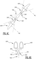
- FIGs 6A-6D show multiple views of luminaire embodiments including one or more tiltable joint according to the present invention.
- the tiltable joint for a luminaire comprises a first joint portion 100, a second joint portion 200, and a first and second shaft portions, parts of a shaft 300 in Figs.6A-6D .
- Part of the tiltable joint may be included in a housing of a luminaire head 600 or may be connected to the luminaire head 600 in any manner known to the skilled person.
- the part of the tiltable joint connected to the luminaire head 600 may be interchangeably the first joint portion 100 or the second joint portion 200, preferably the second joint portion 200.
- the tiltable joint may be connected to a base support 700 such as a luminaire pole to form a luminaire.
- luminaires are street lights or sport lights.
- the tiltable joint may be connected to a wall or another surface.
- the luminaire may be used for illuminating roads, tunnels, industrial plants, stadiums, airports, harbors, rail stations, campuses, parks, cycle paths, pedestrian paths, or pedestrian zones for example.
- the shaft 300 defines an axis of rotation PA and may allow positioning of the luminaire head 600 within an operating range ⁇ of the tiltable joint. In this manner, a main lighting direction ML of the luminaire head 600 may be modified with respect to the surface to be illuminated. It is to be noted that in Figs.6A-6D , the illustrated operating ranges ⁇ and ⁇ ' are not representative of limitative angular ranges but merely serve as indications.
- Figures 6A and 6B show configurations of the luminaire head 600 respective to the base support 700 commonly known as side-entry and post-top configurations, respectively.
- the base support comprises two mounting branches to mount the luminaire head 600 and another luminaire head 600'.
- the luminaire head 600 and the another luminaire head 600' may be similar or different and emit light in the main lighting direction ML and in another main lighting direction ML', respectively.
- the luminaire head 600 and the another luminaire head 600' may be mounted such that their respective main lighting directions ML, ML' are oblique with respect to the surface to be illuminated.
- the luminaire head 600 and the another luminaire head 600' may be mounted to their respective mounting branches via respective tiltable joints.
- the luminaire head 600 may be mounted upwardly, the another luminaire head 600' may be mounted downardly, and the main lighting directions ML, ML' may be parallel to each other in an initial positioning.
- the another tiltable joint of the another luminaire head 600' comprises a first joint portion 100', a second joint portion 200', and a first and second shaft portions, parts of a shaft 300'.
- the tiltable joints of the luminaire head 600 and the another luminaire head 600' may be similar or different.
- the luminaire head 600 and the another luminaire head 600' may be independently positioned within their respective operating ranges ⁇ and ⁇ '.
- the base support 700 may be articulated to provide a broader range of positioning of each of its branches, thus providing a broader range of positioning for the luminaire head 600 and the another luminaire head 600'. Additionally or alternatively, the base support 700 may comprise more than two branches, each pointing in similar of different directions, provided each with a corresponding luminaire head.
- two luminaire heads 600 are coupled via a Y-connector and connected to the second joint portion 200.
- the luminaire heads 600 may be commonly positioned using a single tiltable joint.
- a plurality of luminaire heads 600 forming a subset may be organized in rows and/or columns and be commonly positioned using a tiltable joint according to the invention; a plurality of said subsets may define a luminaire including an array of luminaire heads. Additionally or alternatively, some or all of the luminaire heads in the array may be independently positionable via a dedicated tiltable joint according to the invention.
Landscapes
- Engineering & Computer Science (AREA)
- General Engineering & Computer Science (AREA)
- Mechanical Engineering (AREA)
- Pivots And Pivotal Connections (AREA)
- Non-Portable Lighting Devices Or Systems Thereof (AREA)
- Walking Sticks, Umbrellas, And Fans (AREA)
Claims (15)
- Ein schwenkbares Gelenk (1000) für eine Leuchte, vorzugsweise für eine Außenleuchte, wobei das Gelenk (1000) aufweist:- einen ersten Gelenkabschnitt (100), mit einem Gelenkelement (110), welches mit einem eine Achse aufweisenden äußeren zylindrischen Oberflächenabschnitt und mit entlang der Achse ausgerichteten gegenüberliegenden Lagern (112a, 112b) versehen ist, wobei der äußere zylindrische Oberflächenabschnitt mit einer ersten Mehrzahl an ineinandergreifenden Oberflächen (113) versehen ist;- einen zweiten Gelenkabschnitt (200), mit einem Gelenkgehäuse (210), das mit einem Paar axial ausgerichteter Aufnahmeflächen (212a, 212b) versehen ist, und eine innere zylindrische Fläche aufweist, die mit einer zweiten Mehrzahl an ineinandergreifenden Oberflächen (213) versehen ist, welche so ausgebildet sind, dass sie mit der ersten Mehrzahl an ineinandergreifenden Oberflächen (113) in Eingriff gelangen;- wobei das Gelenkelement (110) des ersten Gelenkabschnitts (100) so ausgebildet ist, dass es in dem Gelenkgehäuse (210) des zweiten Gelenkabschnitts (200) untergebracht ist, wobei die Achse des Paars axial ausgerichteter Lager (112a, 112b) im Wesentlichen parallel zu der Achse des Paars axial ausgerichteter Aufnahmeflächen (212a, 212b) verläuft;- einen ersten und einen zweiten Wellenabschnitt (300a, 300b), welche sich in Ausrichtung mit dem Paar axial ausgerichteter Lager (112a, 112b) erstrecken, so dass eine Schwenkachse (PA) definiert wird;- ein Befestigungsmittel (400), das ausgebildet ist, um:dadurch gekennzeichnet, dass- den Eingriff von mindestens einem Teil der ersten Mehrzahl an ineinandergreifenden Oberflächen (113) mit mindestens einem Teil der zweiten Mehrzahl an ineinandergreifenden Oberflächen (213) zu ermöglichen;- das Lösen des Eingriffs zu ermöglichen, so dass in Bezug auf die durch den ersten und zweiten Wellenabschnitt (300a, 300b) definierte Schwenkachse (PA) eine Drehbewegung des Gelenkgehäuses (210) relativ zu dem Gelenkelement (110) ermöglicht wird;
das Befestigungsmittel (400) ferner so ausgebildet ist, dass es den ersten und den zweiten Wellenabschnitt (300a, 300b) an dem zweiten Gelenkabschnitt (200) befestigt, wobei der erste und der zweite Wellenabschnitt (300a, 300b) von dem Paar axial ausgerichteter Aufnahmeflächen (212a, 212b) aufgenommen werden. - Das schwenkbare Gelenk (1000) nach Anspruch 1, wobei eine Welle (300) den ersten und zweiten Wellenabschnitt (300a, 300b) aufweist; oder wobei eine erste und zweite Welle den ersten bzw. zweiten Wellenabschnitt (300a, 300b) aufweisen.
- Das schwenkbare Gelenk (1000) nach Anspruch 1 oder 2, wobei die erste und zweite Mehrzahl an ineinandergreifenden Oberflächen eine erste bzw. zweite Mehrzahl an ineinandergreifenden Zähnen darstellen.
- Das schwenkbare Gelenk (1000) nach einem der vorherigen Ansprüche, wobei der zweite Gelenkabschnitt (200) so ausgebildet ist, dass er in Bezug auf den ersten Gelenkabschnitt (100), unter einer Mehrzahl an Positionen, in einer ersten Position positioniert werden kann,wobei das Befestigungsmittel (400) so ausgebildet ist, dass es gelöst werden kann, um zu ermöglichen, dass in Bezug auf den ersten Gelenkabschnitt (100) der zweite Gelenkabschnitt (200) von der ersten Position in eine zweite Position der Mehrzahl an Positionen positioniert werden kann, undwobei das Befestigungsmittel (400) ferner so ausgebildet ist, dass es befestigt wird, um in Bezug auf den ersten Gelenkabschnitt (100) eine Bewegung des zweiten Gelenkabschnitts (200) aus der zweiten Position der Mehrzahl an Positionen zu verhindern.
- Das schwenkbare Gelenk (1000) nach einem der vorherigen Ansprüche, wobei sich das Befestigungsmittel (400) in Bezug auf die durch den ersten und zweiten Wellenabschnitt (300a, 300b) definierte Schwenkachse (PA) radial erstreckt; und wobei sich das Befestigungsmittel (400) durch den ersten und zweiten Wellenabschnitt (300a, 300b) erstreckt.
- Das schwenkbare Gelenk (1000) nach einem der vorherigen Ansprüche, wobei der erste und/oder der zweite Wellenabschnitt (300a, 300b) gegenüber der axial ausgerichteten Aufnahmefläche (212a, 212b) einen Absatz (301a, 301b) aufweist, und wobei das Befestigungsmittel (400) ferner so ausgebildet ist, dass es den Eingriff dadurch ermöglicht, dass es den Absatz (301a, 301b) der Aufnahmefläche (212a, 212b) näherbringt.
- Das schwenkbare Gelenk (1000) nach einem der vorherigen Ansprüche, wobei das Befestigungsmittel (400) zumindest einen Bolzen aufweist, der so ausgebildet ist, dass er durch eine Öffnung des ersten und/oder des zweiten Wellenabschnitts (300a, 300b) hindurchgeführt wird, und so ausgebildet ist, dass er am Gelenkgehäuse (210) des zweiten Gelenkabschnitts (200) befestigt wird.
- Das schwenkbare Gelenk (1000) nach einem der vorherigen Ansprüche, wobei der Eingriff des mindestens einen Abschnitts der ersten Mehrzahl an ineinandergreifenden Oberflächen (113) und des mindestens einen Abschnitts der zweiten Mehrzahl an ineinandergreifenden Oberflächen (213) über zumindest einen 90°-Bogen, vorzugsweise über zumindest einen 180°-Bogen, noch bevorzugter über zumindest einen 300°-Bogen, am meisten bevorzugt über zumindest einen 140°-Bogen, der inneren zylindrischen Oberfläche des zweiten Gelenkabschnitts (200) ermöglicht wird.
- Das schwenkbare Gelenk (1000) nach einem der vorherigen Ansprüche, ferner aufweisend einen Winkelanzeiger an zumindest einem der folgenden Teile: dem ersten Gelenkabschnitt (100), dem zweiten Gelenkabschnitt (200), dem ersten Wellenabschnitt (300a) oder dem zweiten Wellenabschnitt (300b).
- Das schwenkbare Gelenk (1000) nach einem der vorherigen Ansprüche, wobei sich eine der ersten oder zweiten Mehrzahl an ineinandergreifenden Oberflächen (113, 213) über einen größeren Winkel erstreckt, als die andere der ersten oder zweiten Mehrzahl an ineinandergreifenden Oberflächen (113, 213).
- Das schwenkbare Gelenk (1000) nach einem der vorherigen Ansprüche, wobei sich die erste Mehrzahl an ineinandergreifenden Oberflächen (113, 213) entlang mindestens zweier paralleler Reihen von ineinandergreifenden Oberflächen erstreckt, und die zweite Mehrzahl von ineinandergreifenden Oberflächen (113, 213) sich entlang mindestens zweier entsprechender paralleler Reihen von ineinandergreifenden Oberflächen erstreckt.
- Das schwenkbare Gelenk (1000) nach einem der vorherigen Ansprüche, wobei der erste Gelenkabschnitt (100) ferner eine Befestigungsstruktur (120) aufweist, die zur Montage des ersten Gelenkteils (100) an einem Basisträger ausgebildet ist.
- Das schwenkbare Gelenk (1000) nach einem der vorherigen Ansprüche, das ferner einen Durchgang für ein Verbindungsmittel zwischen dem ersten Gelenkabschnitt (100) und dem zweiten Gelenkabschnitt (200) aufweist; und
wobei der äußere zylindrische Oberflächenabschnitt vorzugsweise mit einer den Durchgang bildenden Öffnung (130) versehen ist. - Das schwenkbare Gelenk (1000) nach einem der vorherigen Ansprüche, ferner aufweisend ein weiteres Befestigungsmittel, das zum Befestigen des zweiten Gelenkabschnitts (200) an dem ersten Gelenkabschnitt (100) ausgebildet ist.
- Eine Leuchten-System-Anordnung, aufweisend:- einen Grundträger, vorzugsweise mit einem Trägermast;- ein schwenkbares Gelenk nach einem der vorherigen Ansprüche;- einen Leuchtenkopf;- wobei das schwenkbare Gelenk zum Verbinden des Grundträgers und des Leuchtenkopfes ausgebildet ist.
Applications Claiming Priority (2)
| Application Number | Priority Date | Filing Date | Title |
|---|---|---|---|
| NL2022347A NL2022347B1 (en) | 2019-01-07 | 2019-01-07 | Tiltable luminaire joint |
| PCT/EP2020/050229 WO2020144191A1 (en) | 2019-01-07 | 2020-01-07 | Tiltable luminaire joint |
Publications (2)
| Publication Number | Publication Date |
|---|---|
| EP3908784A1 EP3908784A1 (de) | 2021-11-17 |
| EP3908784B1 true EP3908784B1 (de) | 2023-03-01 |
Family
ID=66286870
Family Applications (1)
| Application Number | Title | Priority Date | Filing Date |
|---|---|---|---|
| EP20700556.2A Active EP3908784B1 (de) | 2019-01-07 | 2020-01-07 | Neigbares leuchtengelenk |
Country Status (8)
| Country | Link |
|---|---|
| US (2) | US11920769B2 (de) |
| EP (1) | EP3908784B1 (de) |
| AU (1) | AU2020206970B2 (de) |
| ES (1) | ES2942446T3 (de) |
| NL (1) | NL2022347B1 (de) |
| PL (1) | PL3908784T3 (de) |
| PT (1) | PT3908784T (de) |
| WO (1) | WO2020144191A1 (de) |
Families Citing this family (15)
| Publication number | Priority date | Publication date | Assignee | Title |
|---|---|---|---|---|
| BE1026337B1 (fr) * | 2018-05-28 | 2020-01-13 | Schreder Sa | Element de rotation et de reglage d’angle |
| NL2022347B1 (en) * | 2019-01-07 | 2020-08-13 | Schreder Sa | Tiltable luminaire joint |
| CN212529919U (zh) * | 2020-04-17 | 2021-02-12 | 纳恩博(北京)科技有限公司 | 锁紧机构及具有其的车辆 |
| WO2022069368A1 (en) | 2020-10-01 | 2022-04-07 | Schreder S.A. | Systems and methods for adjusting a rotation angle of a luminaire and attaching a luminaire head |
| NL2026604B1 (en) | 2020-10-01 | 2022-06-02 | Schreder Sa | Systems and methods for adjusting a rotation angle of a luminaire |
| NL2026603B1 (en) | 2020-10-01 | 2022-06-02 | Schreder Sa | Systems and methods for attaching a luminaire head |
| NL2027117B1 (en) | 2020-12-15 | 2022-07-08 | Schreder Sa | Orientable luminaire head, fixation assembly therefor, and method for adjusting an orientation thereof |
| DE102021114366A1 (de) | 2021-06-02 | 2022-12-08 | Trilux Gmbh & Co. Kg | Befestigungsvorrichtung mit verstellbarem Winkel für Außenleuchten |
| NL2032515B1 (en) | 2022-07-15 | 2024-01-25 | Schreder Sa | Modular luminaire head |
| NL2033601B1 (en) | 2022-11-23 | 2024-05-30 | Schreder Sa | Functional head and method for assembling the same |
| NL2033710B1 (en) | 2022-11-24 | 2024-05-30 | Schreder Sa | Luminaire head assembly |
| WO2024110350A1 (en) | 2022-11-24 | 2024-05-30 | Schreder S.A. | Luminaire head assembly |
| NL2035991B1 (en) | 2023-10-09 | 2025-04-16 | Schreder Sa | Connector assembly for a luminaire head |
| NL2035989B1 (en) | 2023-10-09 | 2025-04-16 | Schreder Sa | Connector for attaching a luminaire head to a pole and luminaire with the same |
| NL2037361B1 (en) | 2024-03-28 | 2025-10-10 | Schreder Sa | Sleeve coupling member |
Family Cites Families (6)
| Publication number | Priority date | Publication date | Assignee | Title |
|---|---|---|---|---|
| US5515744A (en) * | 1995-01-06 | 1996-05-14 | Hsin Lung Accessories Co., Ltd. | Adjustable stem member |
| CN201416854Y (zh) * | 2009-07-10 | 2010-03-03 | 浙江晶日照明科技有限公司 | 一种路灯尾部安装管 |
| US9267537B2 (en) * | 2012-04-06 | 2016-02-23 | Koninklijke Philips N.V. | Universal tiltable luminaire support |
| KR102068563B1 (ko) * | 2012-09-21 | 2020-01-21 | 엘지전자 주식회사 | 조명 장치 |
| US11371681B2 (en) * | 2018-09-19 | 2022-06-28 | Signify Holding B.V. | Luminaire mounting |
| NL2022347B1 (en) * | 2019-01-07 | 2020-08-13 | Schreder Sa | Tiltable luminaire joint |
-
2019
- 2019-01-07 NL NL2022347A patent/NL2022347B1/en active
-
2020
- 2020-01-07 EP EP20700556.2A patent/EP3908784B1/de active Active
- 2020-01-07 WO PCT/EP2020/050229 patent/WO2020144191A1/en not_active Ceased
- 2020-01-07 PT PT207005562T patent/PT3908784T/pt unknown
- 2020-01-07 PL PL20700556.2T patent/PL3908784T3/pl unknown
- 2020-01-07 ES ES20700556T patent/ES2942446T3/es active Active
- 2020-01-07 AU AU2020206970A patent/AU2020206970B2/en active Active
- 2020-01-07 US US17/421,262 patent/US11920769B2/en active Active
-
2024
- 2024-02-05 US US18/432,709 patent/US12241619B2/en active Active
Also Published As
| Publication number | Publication date |
|---|---|
| EP3908784A1 (de) | 2021-11-17 |
| PL3908784T3 (pl) | 2023-05-15 |
| AU2020206970B2 (en) | 2023-04-06 |
| WO2020144191A1 (en) | 2020-07-16 |
| AU2020206970A1 (en) | 2021-07-29 |
| ES2942446T3 (es) | 2023-06-01 |
| US11920769B2 (en) | 2024-03-05 |
| NL2022347B1 (en) | 2020-08-13 |
| US20220120420A1 (en) | 2022-04-21 |
| US20240175568A1 (en) | 2024-05-30 |
| US12241619B2 (en) | 2025-03-04 |
| PT3908784T (pt) | 2023-05-09 |
Similar Documents
| Publication | Publication Date | Title |
|---|---|---|
| US12241619B2 (en) | Tiltable luminaire joint | |
| US5452880A (en) | Fence coupling | |
| EP4040033A1 (de) | Reifen und elektronische vorrichtung | |
| US9556893B2 (en) | Omnidirectional breakaway support system and connector | |
| CA2674596A1 (en) | Adapter assembly for pole luminaire | |
| US20130328302A1 (en) | Facilitating access of pole-mounted items | |
| KR101289572B1 (ko) | 조절가능한 풋 베어링 | |
| KR101387362B1 (ko) | 다단 구조의 신호등 또는 가로등에 적용되는 조립형 지주 | |
| KR20230166161A (ko) | 다기능 발광모듈을 포함하는 항공장애등 | |
| EP3346182B1 (de) | Beleuchtungsanordnung zur installation mehrere beleuchtungsvorrichtungen an einer lichtmast | |
| KR20210000630U (ko) | 가로등 지주 고정장치 | |
| EP3853523B1 (de) | Leuchtenhalterung | |
| RU136243U1 (ru) | Устройство для крепления элемента антенны | |
| KR102040430B1 (ko) | 도로 신호등 및 도로표지판용 다단조립식 지주 및 이의 시공 방법 | |
| CN110715234A (zh) | 一种可调式led路灯 | |
| KR101697048B1 (ko) | 각도 조절이 가능한 가로등 | |
| KR100759836B1 (ko) | 가로등지주의 연결장치 | |
| NL2035989B1 (en) | Connector for attaching a luminaire head to a pole and luminaire with the same | |
| CN214535827U (zh) | 一种可调节角度的投光灯 | |
| US10710618B2 (en) | Mounting arrangement for railway wayside signal applications | |
| KR200497800Y1 (ko) | 광의 조사 각도가 제어된 항공장애등 | |
| RU2789794C2 (ru) | Кронштейн универсальный | |
| EP1464881A1 (de) | Befestigungssystem | |
| AU647991B2 (en) | Fence coupling | |
| JP2017206900A (ja) | 柱状体固定具、及び柱状体の固定構造 |
Legal Events
| Date | Code | Title | Description |
|---|---|---|---|
| STAA | Information on the status of an ep patent application or granted ep patent |
Free format text: STATUS: UNKNOWN |
|
| STAA | Information on the status of an ep patent application or granted ep patent |
Free format text: STATUS: THE INTERNATIONAL PUBLICATION HAS BEEN MADE |
|
| PUAI | Public reference made under article 153(3) epc to a published international application that has entered the european phase |
Free format text: ORIGINAL CODE: 0009012 |
|
| STAA | Information on the status of an ep patent application or granted ep patent |
Free format text: STATUS: REQUEST FOR EXAMINATION WAS MADE |
|
| 17P | Request for examination filed |
Effective date: 20210702 |
|
| AK | Designated contracting states |
Kind code of ref document: A1 Designated state(s): AL AT BE BG CH CY CZ DE DK EE ES FI FR GB GR HR HU IE IS IT LI LT LU LV MC MK MT NL NO PL PT RO RS SE SI SK SM TR |
|
| DAV | Request for validation of the european patent (deleted) | ||
| DAX | Request for extension of the european patent (deleted) | ||
| GRAP | Despatch of communication of intention to grant a patent |
Free format text: ORIGINAL CODE: EPIDOSNIGR1 |
|
| STAA | Information on the status of an ep patent application or granted ep patent |
Free format text: STATUS: GRANT OF PATENT IS INTENDED |
|
| INTG | Intention to grant announced |
Effective date: 20220805 |
|
| GRAS | Grant fee paid |
Free format text: ORIGINAL CODE: EPIDOSNIGR3 |
|
| GRAA | (expected) grant |
Free format text: ORIGINAL CODE: 0009210 |
|
| STAA | Information on the status of an ep patent application or granted ep patent |
Free format text: STATUS: THE PATENT HAS BEEN GRANTED |
|
| AK | Designated contracting states |
Kind code of ref document: B1 Designated state(s): AL AT BE BG CH CY CZ DE DK EE ES FI FR GB GR HR HU IE IS IT LI LT LU LV MC MK MT NL NO PL PT RO RS SE SI SK SM TR |
|
| REG | Reference to a national code |
Ref country code: GB Ref legal event code: FG4D |
|
| REG | Reference to a national code |
Ref country code: CH Ref legal event code: EP Ref country code: AT Ref legal event code: REF Ref document number: 1551201 Country of ref document: AT Kind code of ref document: T Effective date: 20230315 |
|
| REG | Reference to a national code |
Ref country code: DE Ref legal event code: R096 Ref document number: 602020008464 Country of ref document: DE |
|
| REG | Reference to a national code |
Ref country code: IE Ref legal event code: FG4D |
|
| REG | Reference to a national code |
Ref country code: PT Ref legal event code: SC4A Ref document number: 3908784 Country of ref document: PT Date of ref document: 20230509 Kind code of ref document: T Free format text: AVAILABILITY OF NATIONAL TRANSLATION Effective date: 20230502 |
|
| REG | Reference to a national code |
Ref country code: NL Ref legal event code: FP |
|
| REG | Reference to a national code |
Ref country code: ES Ref legal event code: FG2A Ref document number: 2942446 Country of ref document: ES Kind code of ref document: T3 Effective date: 20230601 |
|
| P01 | Opt-out of the competence of the unified patent court (upc) registered |
Effective date: 20230515 |
|
| REG | Reference to a national code |
Ref country code: LT Ref legal event code: MG9D |
|
| PG25 | Lapsed in a contracting state [announced via postgrant information from national office to epo] |
Ref country code: RS Free format text: LAPSE BECAUSE OF FAILURE TO SUBMIT A TRANSLATION OF THE DESCRIPTION OR TO PAY THE FEE WITHIN THE PRESCRIBED TIME-LIMIT Effective date: 20230301 Ref country code: NO Free format text: LAPSE BECAUSE OF FAILURE TO SUBMIT A TRANSLATION OF THE DESCRIPTION OR TO PAY THE FEE WITHIN THE PRESCRIBED TIME-LIMIT Effective date: 20230601 Ref country code: LV Free format text: LAPSE BECAUSE OF FAILURE TO SUBMIT A TRANSLATION OF THE DESCRIPTION OR TO PAY THE FEE WITHIN THE PRESCRIBED TIME-LIMIT Effective date: 20230301 Ref country code: LT Free format text: LAPSE BECAUSE OF FAILURE TO SUBMIT A TRANSLATION OF THE DESCRIPTION OR TO PAY THE FEE WITHIN THE PRESCRIBED TIME-LIMIT Effective date: 20230301 Ref country code: HR Free format text: LAPSE BECAUSE OF FAILURE TO SUBMIT A TRANSLATION OF THE DESCRIPTION OR TO PAY THE FEE WITHIN THE PRESCRIBED TIME-LIMIT Effective date: 20230301 |
|
| REG | Reference to a national code |
Ref country code: AT Ref legal event code: MK05 Ref document number: 1551201 Country of ref document: AT Kind code of ref document: T Effective date: 20230301 |
|
| PG25 | Lapsed in a contracting state [announced via postgrant information from national office to epo] |
Ref country code: SE Free format text: LAPSE BECAUSE OF FAILURE TO SUBMIT A TRANSLATION OF THE DESCRIPTION OR TO PAY THE FEE WITHIN THE PRESCRIBED TIME-LIMIT Effective date: 20230301 Ref country code: GR Free format text: LAPSE BECAUSE OF FAILURE TO SUBMIT A TRANSLATION OF THE DESCRIPTION OR TO PAY THE FEE WITHIN THE PRESCRIBED TIME-LIMIT Effective date: 20230602 Ref country code: FI Free format text: LAPSE BECAUSE OF FAILURE TO SUBMIT A TRANSLATION OF THE DESCRIPTION OR TO PAY THE FEE WITHIN THE PRESCRIBED TIME-LIMIT Effective date: 20230301 |
|
| PG25 | Lapsed in a contracting state [announced via postgrant information from national office to epo] |
Ref country code: SM Free format text: LAPSE BECAUSE OF FAILURE TO SUBMIT A TRANSLATION OF THE DESCRIPTION OR TO PAY THE FEE WITHIN THE PRESCRIBED TIME-LIMIT Effective date: 20230301 Ref country code: RO Free format text: LAPSE BECAUSE OF FAILURE TO SUBMIT A TRANSLATION OF THE DESCRIPTION OR TO PAY THE FEE WITHIN THE PRESCRIBED TIME-LIMIT Effective date: 20230301 Ref country code: EE Free format text: LAPSE BECAUSE OF FAILURE TO SUBMIT A TRANSLATION OF THE DESCRIPTION OR TO PAY THE FEE WITHIN THE PRESCRIBED TIME-LIMIT Effective date: 20230301 Ref country code: CZ Free format text: LAPSE BECAUSE OF FAILURE TO SUBMIT A TRANSLATION OF THE DESCRIPTION OR TO PAY THE FEE WITHIN THE PRESCRIBED TIME-LIMIT Effective date: 20230301 Ref country code: AT Free format text: LAPSE BECAUSE OF FAILURE TO SUBMIT A TRANSLATION OF THE DESCRIPTION OR TO PAY THE FEE WITHIN THE PRESCRIBED TIME-LIMIT Effective date: 20230301 |
|
| PG25 | Lapsed in a contracting state [announced via postgrant information from national office to epo] |
Ref country code: SK Free format text: LAPSE BECAUSE OF FAILURE TO SUBMIT A TRANSLATION OF THE DESCRIPTION OR TO PAY THE FEE WITHIN THE PRESCRIBED TIME-LIMIT Effective date: 20230301 Ref country code: IS Free format text: LAPSE BECAUSE OF FAILURE TO SUBMIT A TRANSLATION OF THE DESCRIPTION OR TO PAY THE FEE WITHIN THE PRESCRIBED TIME-LIMIT Effective date: 20230701 |
|
| REG | Reference to a national code |
Ref country code: DE Ref legal event code: R097 Ref document number: 602020008464 Country of ref document: DE |
|
| PLBE | No opposition filed within time limit |
Free format text: ORIGINAL CODE: 0009261 |
|
| STAA | Information on the status of an ep patent application or granted ep patent |
Free format text: STATUS: NO OPPOSITION FILED WITHIN TIME LIMIT |
|
| PG25 | Lapsed in a contracting state [announced via postgrant information from national office to epo] |
Ref country code: SI Free format text: LAPSE BECAUSE OF FAILURE TO SUBMIT A TRANSLATION OF THE DESCRIPTION OR TO PAY THE FEE WITHIN THE PRESCRIBED TIME-LIMIT Effective date: 20230301 Ref country code: DK Free format text: LAPSE BECAUSE OF FAILURE TO SUBMIT A TRANSLATION OF THE DESCRIPTION OR TO PAY THE FEE WITHIN THE PRESCRIBED TIME-LIMIT Effective date: 20230301 |
|
| 26N | No opposition filed |
Effective date: 20231204 |
|
| PG25 | Lapsed in a contracting state [announced via postgrant information from national office to epo] |
Ref country code: MC Free format text: LAPSE BECAUSE OF FAILURE TO SUBMIT A TRANSLATION OF THE DESCRIPTION OR TO PAY THE FEE WITHIN THE PRESCRIBED TIME-LIMIT Effective date: 20230301 |
|
| PG25 | Lapsed in a contracting state [announced via postgrant information from national office to epo] |
Ref country code: MC Free format text: LAPSE BECAUSE OF FAILURE TO SUBMIT A TRANSLATION OF THE DESCRIPTION OR TO PAY THE FEE WITHIN THE PRESCRIBED TIME-LIMIT Effective date: 20230301 |
|
| REG | Reference to a national code |
Ref country code: CH Ref legal event code: PL |
|
| PG25 | Lapsed in a contracting state [announced via postgrant information from national office to epo] |
Ref country code: LU Free format text: LAPSE BECAUSE OF NON-PAYMENT OF DUE FEES Effective date: 20240107 |
|
| PG25 | Lapsed in a contracting state [announced via postgrant information from national office to epo] |
Ref country code: LU Free format text: LAPSE BECAUSE OF NON-PAYMENT OF DUE FEES Effective date: 20240107 |
|
| PG25 | Lapsed in a contracting state [announced via postgrant information from national office to epo] |
Ref country code: CH Free format text: LAPSE BECAUSE OF NON-PAYMENT OF DUE FEES Effective date: 20240131 |
|
| PG25 | Lapsed in a contracting state [announced via postgrant information from national office to epo] |
Ref country code: CH Free format text: LAPSE BECAUSE OF NON-PAYMENT OF DUE FEES Effective date: 20240131 |
|
| PG25 | Lapsed in a contracting state [announced via postgrant information from national office to epo] |
Ref country code: BG Free format text: LAPSE BECAUSE OF FAILURE TO SUBMIT A TRANSLATION OF THE DESCRIPTION OR TO PAY THE FEE WITHIN THE PRESCRIBED TIME-LIMIT Effective date: 20230301 |
|
| PG25 | Lapsed in a contracting state [announced via postgrant information from national office to epo] |
Ref country code: BG Free format text: LAPSE BECAUSE OF FAILURE TO SUBMIT A TRANSLATION OF THE DESCRIPTION OR TO PAY THE FEE WITHIN THE PRESCRIBED TIME-LIMIT Effective date: 20230301 |
|
| PG25 | Lapsed in a contracting state [announced via postgrant information from national office to epo] |
Ref country code: IE Free format text: LAPSE BECAUSE OF NON-PAYMENT OF DUE FEES Effective date: 20240107 |
|
| PG25 | Lapsed in a contracting state [announced via postgrant information from national office to epo] |
Ref country code: IE Free format text: LAPSE BECAUSE OF NON-PAYMENT OF DUE FEES Effective date: 20240107 |
|
| PG25 | Lapsed in a contracting state [announced via postgrant information from national office to epo] |
Ref country code: CY Free format text: LAPSE BECAUSE OF FAILURE TO SUBMIT A TRANSLATION OF THE DESCRIPTION OR TO PAY THE FEE WITHIN THE PRESCRIBED TIME-LIMIT; INVALID AB INITIO Effective date: 20200107 |
|
| PG25 | Lapsed in a contracting state [announced via postgrant information from national office to epo] |
Ref country code: HU Free format text: LAPSE BECAUSE OF FAILURE TO SUBMIT A TRANSLATION OF THE DESCRIPTION OR TO PAY THE FEE WITHIN THE PRESCRIBED TIME-LIMIT; INVALID AB INITIO Effective date: 20200107 |
|
| PG25 | Lapsed in a contracting state [announced via postgrant information from national office to epo] |
Ref country code: TR Free format text: LAPSE BECAUSE OF FAILURE TO SUBMIT A TRANSLATION OF THE DESCRIPTION OR TO PAY THE FEE WITHIN THE PRESCRIBED TIME-LIMIT Effective date: 20230301 |
|
| PGFP | Annual fee paid to national office [announced via postgrant information from national office to epo] |
Ref country code: GB Payment date: 20251217 Year of fee payment: 7 |
|
| PGFP | Annual fee paid to national office [announced via postgrant information from national office to epo] |
Ref country code: PT Payment date: 20251217 Year of fee payment: 7 |
|
| PGFP | Annual fee paid to national office [announced via postgrant information from national office to epo] |
Ref country code: NL Payment date: 20251217 Year of fee payment: 7 Ref country code: FR Payment date: 20251217 Year of fee payment: 7 |
|
| PGFP | Annual fee paid to national office [announced via postgrant information from national office to epo] |
Ref country code: BE Payment date: 20251217 Year of fee payment: 7 |
|
| PGFP | Annual fee paid to national office [announced via postgrant information from national office to epo] |
Ref country code: PL Payment date: 20251223 Year of fee payment: 7 |
|
| PGFP | Annual fee paid to national office [announced via postgrant information from national office to epo] |
Ref country code: ES Payment date: 20260202 Year of fee payment: 7 |
|
| PGFP | Annual fee paid to national office [announced via postgrant information from national office to epo] |
Ref country code: DE Payment date: 20251217 Year of fee payment: 7 |
|
| PGFP | Annual fee paid to national office [announced via postgrant information from national office to epo] |
Ref country code: IT Payment date: 20260107 Year of fee payment: 7 |