EP3907564A1 - Élément d'indexation d'horlogerie - Google Patents
Élément d'indexation d'horlogerie Download PDFInfo
- Publication number
- EP3907564A1 EP3907564A1 EP20172880.5A EP20172880A EP3907564A1 EP 3907564 A1 EP3907564 A1 EP 3907564A1 EP 20172880 A EP20172880 A EP 20172880A EP 3907564 A1 EP3907564 A1 EP 3907564A1
- Authority
- EP
- European Patent Office
- Prior art keywords
- indexing
- component
- indexing element
- relief
- bearing surface
- Prior art date
- Legal status (The legal status is an assumption and is not a legal conclusion. Google has not performed a legal analysis and makes no representation as to the accuracy of the status listed.)
- Pending
Links
- 230000000295 complement effect Effects 0.000 claims abstract description 13
- 230000007246 mechanism Effects 0.000 claims description 21
- OFNHPGDEEMZPFG-UHFFFAOYSA-N phosphanylidynenickel Chemical compound [P].[Ni] OFNHPGDEEMZPFG-UHFFFAOYSA-N 0.000 claims description 2
- 230000000903 blocking effect Effects 0.000 description 4
- 238000004519 manufacturing process Methods 0.000 description 4
- 238000005452 bending Methods 0.000 description 2
- 238000000605 extraction Methods 0.000 description 2
- 239000000463 material Substances 0.000 description 2
- 230000000284 resting effect Effects 0.000 description 2
- 230000035939 shock Effects 0.000 description 2
- 230000007704 transition Effects 0.000 description 2
- PEDCQBHIVMGVHV-UHFFFAOYSA-N Glycerine Chemical compound OCC(O)CO PEDCQBHIVMGVHV-UHFFFAOYSA-N 0.000 description 1
- VYPSYNLAJGMNEJ-UHFFFAOYSA-N Silicium dioxide Chemical compound O=[Si]=O VYPSYNLAJGMNEJ-UHFFFAOYSA-N 0.000 description 1
- XUIMIQQOPSSXEZ-UHFFFAOYSA-N Silicon Chemical compound [Si] XUIMIQQOPSSXEZ-UHFFFAOYSA-N 0.000 description 1
- 240000008042 Zea mays Species 0.000 description 1
- 230000000703 anti-shock Effects 0.000 description 1
- 230000008859 change Effects 0.000 description 1
- 239000000470 constituent Substances 0.000 description 1
- 238000010586 diagram Methods 0.000 description 1
- 239000006185 dispersion Substances 0.000 description 1
- 230000009191 jumping Effects 0.000 description 1
- 238000001459 lithography Methods 0.000 description 1
- 238000012423 maintenance Methods 0.000 description 1
- 230000014759 maintenance of location Effects 0.000 description 1
- 238000000034 method Methods 0.000 description 1
- 230000008569 process Effects 0.000 description 1
- 229910052710 silicon Inorganic materials 0.000 description 1
- 239000010703 silicon Substances 0.000 description 1
- 229910052814 silicon oxide Inorganic materials 0.000 description 1
- 238000004804 winding Methods 0.000 description 1
Images


Classifications
-
- G—PHYSICS
- G04—HOROLOGY
- G04B—MECHANICALLY-DRIVEN CLOCKS OR WATCHES; MECHANICAL PARTS OF CLOCKS OR WATCHES IN GENERAL; TIME PIECES USING THE POSITION OF THE SUN, MOON OR STARS
- G04B13/00—Gearwork
- G04B13/02—Wheels; Pinions; Spindles; Pivots
- G04B13/021—Wheels; Pinions; Spindles; Pivots elastic fitting with a spindle, axis or shaft
-
- G—PHYSICS
- G04—HOROLOGY
- G04B—MECHANICALLY-DRIVEN CLOCKS OR WATCHES; MECHANICAL PARTS OF CLOCKS OR WATCHES IN GENERAL; TIME PIECES USING THE POSITION OF THE SUN, MOON OR STARS
- G04B11/00—Click devices; Stop clicks; Clutches
- G04B11/001—Clutch mechanism between two rotating members with transfer of movement in both directions, possibly with limitation on the transfer of power
- G04B11/003—Clutch mechanism between two rotating members with transfer of movement in both directions, possibly with limitation on the transfer of power with friction member, e.g. with spring action
-
- G—PHYSICS
- G04—HOROLOGY
- G04B—MECHANICALLY-DRIVEN CLOCKS OR WATCHES; MECHANICAL PARTS OF CLOCKS OR WATCHES IN GENERAL; TIME PIECES USING THE POSITION OF THE SUN, MOON OR STARS
- G04B13/00—Gearwork
- G04B13/02—Wheels; Pinions; Spindles; Pivots
-
- G—PHYSICS
- G04—HOROLOGY
- G04B—MECHANICALLY-DRIVEN CLOCKS OR WATCHES; MECHANICAL PARTS OF CLOCKS OR WATCHES IN GENERAL; TIME PIECES USING THE POSITION OF THE SUN, MOON OR STARS
- G04B11/00—Click devices; Stop clicks; Clutches
- G04B11/02—Devices allowing the motion of a rotatable part in only one direction
- G04B11/04—Pawl constructions therefor, e.g. pawl secured to an oscillating member actuating a ratchet
-
- G—PHYSICS
- G04—HOROLOGY
- G04B—MECHANICALLY-DRIVEN CLOCKS OR WATCHES; MECHANICAL PARTS OF CLOCKS OR WATCHES IN GENERAL; TIME PIECES USING THE POSITION OF THE SUN, MOON OR STARS
- G04B13/00—Gearwork
- G04B13/02—Wheels; Pinions; Spindles; Pivots
- G04B13/021—Wheels; Pinions; Spindles; Pivots elastic fitting with a spindle, axis or shaft
- G04B13/023—Wheels; Pinions; Spindles; Pivots elastic fitting with a spindle, axis or shaft allowing rotational slipping when a threshold torque is exceeded
-
- G—PHYSICS
- G04—HOROLOGY
- G04B—MECHANICALLY-DRIVEN CLOCKS OR WATCHES; MECHANICAL PARTS OF CLOCKS OR WATCHES IN GENERAL; TIME PIECES USING THE POSITION OF THE SUN, MOON OR STARS
- G04B31/00—Bearings; Point suspensions or counter-point suspensions; Pivot bearings; Single parts therefor
- G04B31/02—Shock-damping bearings
-
- G—PHYSICS
- G04—HOROLOGY
- G04B—MECHANICALLY-DRIVEN CLOCKS OR WATCHES; MECHANICAL PARTS OF CLOCKS OR WATCHES IN GENERAL; TIME PIECES USING THE POSITION OF THE SUN, MOON OR STARS
- G04B43/00—Protecting clockworks by shields or other means against external influences, e.g. magnetic fields
- G04B43/002—Component shock protection arrangements
Definitions
- the invention relates to a timepiece indexing element, arranged to cooperate in a substantially coaxial manner, around an axis around which said indexing element extends, with a timepiece component comprising an indexing relief defining a plurality of indexing positions, said indexing element comprising a first bearing surface arranged to cooperate in abutment bearing with a second complementary bearing surface that a said component comprises, and comprising elastic return means arranged to exerting a thrust force that is substantially radial with respect to said axis on a said component in order to press it against said first bearing surface, and comprising indexing means arranged to cooperate with a said indexing relief of a said component for relative indexing between said indexing element and said component.
- the invention also relates to a timepiece assembly comprising at least one such indexing element, and at least one such timepiece component comprising an indexing relief defining a plurality of indexing positions, said at least one indexing element. and said at least one component being arranged to cooperate with one another in a substantially coaxial manner, around said axis, for their relative indexing with respect to one another.
- the invention also relates to a timepiece mechanism comprising at least one such indexing element, and / or such a timepiece assembly.
- the invention also relates to a timepiece, in particular a watch, comprising at least one such timepiece mechanism and / or at least one such indexing element, and / or such a timepiece assembly.
- the invention also relates to the field of clockwork mechanisms, and in particular display, and / or adjustment, and / or selection mechanisms.
- time zone / jumping hour wheels consist of several boards / pinions, linked together by a star / cam constrained by a spring element (pawl).
- pawl spring element
- the invention proposes both to make the adjustment and indexing mechanisms more reliable, to reduce their thickness, and to guarantee precise and controlled indexing between two elements.
- the invention relates to a timepiece indexing element, according to claim 1.
- the invention also relates to a timepiece assembly comprising at least one such indexing element, and at least one such timepiece component comprising an indexing relief defining a plurality of indexing positions, said at least one indexing element. and said at least one component being arranged to cooperate with one another in a substantially coaxial manner, for their relative indexing with respect to one another.
- the invention also relates to a timepiece mechanism comprising at least one such indexing element, and / or such a timepiece assembly.
- the invention also relates to a timepiece, in particular a watch, comprising at least one such timepiece mechanism and / or at least one such indexing element, and / or such a timepiece assembly.
- the invention relates to a timepiece indexing element 10, arranged to cooperate in a substantially coaxial manner, around an axis D around which this indexing element 10 extends, with a timepiece component 20:
- This component 20 comprises an indexing relief 30, defining a plurality of indexing positions.
- This indexing relief can be formed by a toothing as illustrated by the figures, or by a groove, or by notches, or protrusions, or pins, or the like.
- the indexing element 10 comprises a first bearing surface 11, which is arranged to cooperate, at least in the shock configuration, in abutment and / or guide bearing with a second complementary bearing surface 21 which a such component 20.
- first bearing surface 11 which is arranged to cooperate, at least in the shock configuration, in abutment and / or guide bearing with a second complementary bearing surface 21 which a such component 20.
- second complementary bearing surface 21 which a such component 20.
- this zone of contact between the indexing element 10 and the component 20 ensures the perfect positioning of one relative to the other: their position is both known and controlled.
- each first bearing surface 11 in normal operation, in the service position, is at a distance from a second complementary bearing surface 21, with a non-zero clearance, of a few micrometers or tens of micrometers. In the event of an impact, the first bearing surface 11 performs both a stop function and a guiding function of the component 20.
- the indexing element 10 comprises elastic return means, marked 12 on the figures 1 to 6 , which are arranged to exert a thrust force that is substantially radial, with respect to the axis D, on such a component 20, to press it against a contact surface, or on the support surface 11.
- the indexing element 10 comprises indexing means 13, which are arranged to cooperate with an indexing relief 30 of a component 20 for relative indexing between the indexing element 10 and this component 20.
- indexing means 13 are in particular teeth, lugs, or the like.
- the elastic return means 12 comprise at least a first elastic arm 14, comprising a first indexing surface 15 which the indexing means 13 comprise. And this first elastic arm 14 is arranged to exert a thrust force that is substantially radial with respect to the axis D on such a component 20.
- the elastic return means 12 further comprise at least one second elastic arm 16, which is arranged to exert a thrust force that is substantially radial with respect to the axis D on at least one first elastic arm 14. More particularly, in a pair formed by a first elastic arm 14 and a second elastic arm 16, the second elastic arm 16 is arranged to exert a return torque greater than the return torque of the first elastic arm 14. More particularly, in a pair formed by a first arm elastic 14 and a second elastic arm 16, the second elastic arm 16 is arranged to travel, in its bending stroke, a radial extension (or deflection) less than that of the first elastic arm 14.
- the first inner elastic arm 14 has an arrow of 0.26 mm, while that of the second elastic arm 16 is 0.21 mm.
- the indexing element 10 comprises a plurality of pairs (two pairs in the non-limiting case of the figures), each constituted by a first elastic arm 14 and a second elastic arm 16, and each arranged to exert on a component 20 a force substantially diametrically opposed, with respect to the axis D, to the first bearing surface 11.
- At least one second elastic arm 16 comprises a lug 17 which is arranged to cooperate with a notch 18 which a first arm comprises elastic 14 with which this second elastic arm 16 cooperates, for locking in the indexing position of this first elastic arm 14, in the factory or in an after-sales service; to be implemented by a user, such a variant requires the arrangement of additional means, not illustrated here, to release the lug 17 from the notch 18.
- the indexing element 10 comprises at least one locking element.
- the blocking 19 which is arranged to block a second elastic arm 16 resting on a first elastic arm 14 with which this second elastic arm 16 cooperates; this blocking can be a blocking with a slight play, to allow a small radial travel of the first elastic arm 14 and of the second elastic arm 16 in the event of impact, when the mechanism is incorporated into a watch ; here again, such a blockage relates to a factory setting or in an after-sales service.
- the first elastic arm 14 and the second elastic arm 16 are substantially parallel to one another.
- the first elastic arms 14 and second elastic arms 16 are curved, in particular substantially circular and centered on the axis D, for a good distribution of the stresses.
- the indexing element 10 comprises an internal chamber 111, delimited by the bearing surface 11 and each first elastic arm 14, and which is arranged to surround an indexing relief 30 of a component 20, and each first elastic arm 14 is closer to the axis D than each second elastic arm 16.
- the indexing element 10 is arranged to be inserted into an external chamber delimited by an indexing relief 30 of a component 20, and each first elastic arm 14 is further from the axis D than each second elastic arm 16.
- the indexing element 10 comprises at least one boss 110 diametrically opposed, with respect to the axis D, to the first bearing surface 11, to constitute an anti-shock stop limiting the relative radial movement, in the event of shock, between the indexing element 10 and a component 20 assembled together in an indexed position.
- the figure 8 illustrates a mechanism according to the invention, arranged to ensure proper operation, with maintenance of the geometry, even in the event of an impact.
- the invention relates to a timepiece indexing element 10, arranged to cooperate in a substantially coaxial manner, around an axis D around which this indexing element 10 extends, with a timepiece component 20 comprising a indexing relief 30.
- the indexing element 10 comprises indexing means 13, which are arranged to cooperate with such an indexing relief 30 of a component 20, for relative indexing between this indexing element. 10 and this component 20 from among a plurality of relative indexing positions.
- these indexing means 13 are carried by a plurality of first elastic arms 14 each comprising a first indexing surface 15, each first elastic arm 14 being arranged to exert a thrust force that is substantially radial with respect to the 'axis D on this component 20.
- the indexing element 10 comprises at least a first bearing surface 11, which is arranged to, in the free state in a service position, remain at a distance from a second complementary bearing surface 21 that comprises a component 20, and in the event of an impact, cooperate in abutment and / or guide bearing with the second complementary bearing surface 21.
- each first bearing surface 11 and each second complementary bearing surface 21 is strictly positive, that is to say not zero.
- each first bearing surface 11 is carried by a second arm 40 cantilevered inside the indexing element 10.
- at least one second arm 40, and more particularly each second arm 40 is elastic.
- the indexing element 10 comprises a plurality of first bearing surfaces 11, which are arranged to surround a component 20 and keep it substantially coaxial with the indexing element 10 in the event of an impact.
- each first bearing surface 11 is arranged to cooperate simultaneously with several protruding reliefs 31, in particular teeth, which the indexing relief 30 of component 20 comprises.
- each second arm 40 comprises a first external limiting surface 41, which is arranged to limit the centripetal travel of a first elastic arm 14 or to move a first elastic arm 14 away from the axis D during an impact.
- the indexing element 10 comprises an alternation of second arms 40 and first elastic arms 14, all projecting internally from a substantially annular structure, towards the axis D.
- each first elastic arm 14 comprises a housing 150 or a protuberance for its operation by a concentric clamping tool for its bringing into cooperation with an indexing relief 30 of a component 20, or for its removal.
- each second arm 40 comprises a second internal limiting surface 42, which is arranged to limit the centrifugal stroke of a first elastic arm 14.
- the invention can be used indifferently with the movable indexing element 10 and the fixed component 20, or the fixed indexing element 10 and the movable component 20, or the indexing element 10 and the component 20 both movable, or even the indexing element 10 and the component 20 both fixed for a factory setting for example.
- the indexing element 10 is a mobile arranged to pivot around the axis D and around a component 20 with which it cooperates.
- the indexing element 10 comprises drive means 120, such as teeth, grooves, notches, bores, projections, pins, pins, belt or chain groove, or the like.
- the indexing element 10 is designed to be fixed in a fixed angular position on a structure of a movement or of a clockwork mechanism.
- the indexing element 10 is made of a micro-machinable material, which can be produced by a process of the “LIGA” type (from the German “Rôntgenlithographie, Galvanoformung, Abformung”: lithography, galvanization, forming) or similar, in silicon , or silicon oxide, or nickel-phosphorus NiP, or any similar material now in common use in watchmaking and suitable for making thin monobloc components comprising elastic blades.
- the invention lends itself particularly well to the production of components for watches, of small dimensions, for example with an overall diameter of less than 5 mm, and a thickness of a few tenths of a millimeter.
- the invention also relates to a timepiece assembly 100 comprising at least one such indexing element 10, and at least one such timepiece component 20 comprising an indexing relief 30 defining a plurality of indexing positions.
- This at least one indexing element 10 and this at least one component 20 are arranged to cooperate with each other in a substantially coaxial manner, around the axis D, for their relative indexing with respect to one another. 'other, with the first bearing surface 11 arranged to cooperate in abutment bearing with a second complementary bearing surface 21 which this at least one component 20 comprises, and the indexing means 13 arranged to cooperate with a relief d indexing 30 of such a component 20 for relative indexing between the indexing element 10 and the component 20 concerned.
- the indexing element 10 comprises an internal chamber 111, delimited by the bearing surface 11 and each first arm elastic 14, arranged to surround an indexing relief 30 of a component 20, and each first elastic arm 14 is closer to the axis D than each second elastic arm 16.
- the indexing element 10 is arranged to be inserted into an external chamber delimited by an indexing relief 30 of a component 20, and each first elastic arm 14 is further from the axis D than each second elastic arm 16.
- the watch assembly 100 comprises a single indexing element 10, and a single component 20.
- component 20 is a mobile.
- the component 20 is designed to be fixed in a fixed angular position on a structure of a movement or of a clockwork mechanism.
- the indexing element 10 and the indexing relief 30 of the component 20 are both delimited by the same upper plane and the same lower plane, perpendicular to the axis D. More particularly still, they have the same thickness.
- the invention also relates to a timepiece mechanism 500 comprising at least one such indexing element 10, and / or such a timepiece assembly 100.
- the invention also relates to a timepiece 1000, in particular a watch, comprising at least one such timepiece mechanism 500, and / or at least one indexing element 10, and / or a timepiece assembly 100.
- the invention while ensuring the disengagement of the two indexed elements, makes it possible to gain a level in Z, that is, ie to reduce the total thickness.
- one of the elastic arms provides positioning and indexing, and part of the support torque, and the other spring provides most of the resulting support torque.
- indexing element 10 and a component 20 which are both toothed wheels
- the invention lends itself to numerous horological applications: column wheel, date ring, date indicator. time zone, toggle, display disc, day / night indicator, AM / PM indicator, leap year display, moon phase, or other.
- the invention makes it possible to obtain an appreciable gain in terms of bulk, in particular in thickness, to minimize the risk of breakage of the spring elements, and to ensure better control of the forces.
Landscapes
- Physics & Mathematics (AREA)
- General Physics & Mathematics (AREA)
- Micromachines (AREA)
- Electromechanical Clocks (AREA)
Abstract
Description
- L'invention concerne un élément d'indexation d'horlogerie, agencé pour coopérer de façon sensiblement coaxiale, autour d'un axe autour duquel s'étend ledit élément d'indexation, avec un composant d'horlogerie comportant un relief d'indexage définissant une pluralité de positions d'indexage, ledit élément d'indexation comportant une première surface d'appui agencée pour coopérer en appui de butée avec une deuxième surface d'appui complémentaire que comporte un dit composant, et comportant des moyens de rappel élastique agencés pour exercer un effort de poussée sensiblement radial par rapport audit axe sur un dit composant pour le plaquer en appui sur ladite première surface d'appui, et comportant des moyens d'indexation agencés pour coopérer avec un dit relief d'indexage d'un dit composant pour un indexage relatif entre ledit élément d'indexation et ce dit composant.
- L'invention concerne encore un ensemble horloger comportant au moins un tel élément d'indexation, et au moins un tel composant d'horlogerie comportant un relief d'indexage définissant une pluralité de positions d'indexage, ledit au moins un élément d'indexation et ledit au moins un composant étant agencés pour coopérer l'un avec l'autre de façon sensiblement coaxiale, autour dudit axe, pour leur indexage relatif l'un par rapport à l'autre.
- L'invention concerne encore un mécanisme d'horlogerie comportant au moins un tel élément d'indexation, et/ou un tel ensemble horloger.
- L'invention concerne encore une pièce d'horlogerie, notamment une montre, comportant au moins un tel mécanisme d'horlogerie et/ou au moins un tel élément d'indexation, et/ou un tel ensemble horloger.
- L'invention concerne encore le domaine des mécanismes d'horlogerie, et en particulier des mécanismes d'affichage, et/ou de réglage, et/ou de sélection.
- Dans des mécanismes d'affichage d'horlogerie tels que des affichages de fuseau horaire, souvent les roues fuseau/heures sautantes sont constituées de plusieurs planches/pignons, liées ensemble par une étoile/came contrainte par un élément ressort (cliquet). De tels systèmes ont un encombrement important.
- Les éléments ressorts de ces systèmes sont souvent poussé à leur maximum, ce qui ne permet pas d'obtenir des valeurs importantes de flèches, pourtant nécessaires pour assurer l'armage et le fonctionnement. De surcroît les variations dimensionnelles lors de la production entraînent des variations de forces significatives au niveau de ces ressorts, les efforts ne sont pas reproductibles.
- L'invention se propose à la fois de fiabiliser les mécanismes de réglage et d'indexage, de réduire leur l'épaisseur, et de garantir une indexation précise et maîtrisée entre deux éléments.
- Il s'agit, encore, de limiter les contraintes subies par les éléments élastiques.
- Et il faut enfin, s'affranchir de la dispersion des valeurs des forces, imputables à la difficulté de respecter, de façon reproductible, les tolérances de production.
- A cet effet, l'invention concerne un élément d'indexation d'horlogerie, selon la revendication 1.
- L'invention concerne encore un ensemble horloger comportant au moins un tel élément d'indexation, et au moins un tel composant d'horlogerie comportant un relief d'indexage définissant une pluralité de positions d'indexage, ledit au moins un élément d'indexation et ledit au moins un composant étant agencés pour coopérer l'un avec l'autre de façon sensiblement coaxiale, pour leur indexage relatif l'un par rapport à l'autre.
- L'invention concerne encore un mécanisme d'horlogerie comportant au moins un tel élément d'indexation, et/ou un tel ensemble horloger.
- L'invention concerne encore une pièce d'horlogerie, notamment une montre, comportant au moins un tel mécanisme d'horlogerie et/ou au moins un tel élément d'indexation, et/ou un tel ensemble horloger.
- D'autres caractéristiques et avantages de l'invention apparaîtront à la lecture de la description détaillée qui va suivre, en référence aux dessins annexés, où :
- la
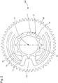
figure 1 représente, de façon schématisée, et en plat, un ensemble horloger comportant d'une part un élément d'indexation qui est ici une roue dentée comportant, découpés dans sa planche, deux paires de bras élastiques, et d'autre part un composant d'horlogerie comportant un relief d'indexage définissant une pluralité de positions d'indexage, ce relief d'indexage étant ici constitué par une denture ; cet élément d'indexation et ce composant coopèrent l'un avec l'autre de façon coaxiale, en appui l'un dans l'autre. Dans chaque paire de bras élastiques le bras le plus interne effectue l'indexation en coopérant avec le relief d'indexage, et effectue une première pression sur ce dernier. Dans chaque paire le bras élastique le plus externe, coplanaire au bras interne, appuie sur ce dernier avec un couple de rappel supérieur au sien. Cette figure est représentée dans une position indexée stable ; - la
figure 2 représente, de façon similaire à lafigure 1 , le même mécanisme dans une position de transition, dans laquelle les bras élastiques internes sont en appui sur les sommets de dents du relief d'indexage ; les bras élastiques internes et externes sont alors dans leur élongation radiale maximale ; - la
figure 3 représente, de façon similaire à lafigure 1 , l'élément d'indexation seul, à l'état libre, dans lequel les bras élastiques internes et externes sont en position de repos, au plus près de l'axe ; - la
figure 4 représente, de façon similaire à lafigure 1 , une configuration inverse, où le composant comportant le relief d'indexage entoure l'élément d'indexation, et où les bras élastiques externes coopèrent avec ce dernier, tandis que les bras élastiques internes appuient sur les bras élastiques externes ; - la
figure 5 représente, de façon similaire à lafigure 1 , un détail d'une variante où le bras élastique interne comporte un cran avec lequel peut coopérer un bossage du bras élastique externe ; - la
figure 6 représente, de façon similaire à lafigure 1 , un détail d'une autre variante où un élément de blocage tel qu'une goupille est inséré en usine après un réglage, pour limiter le débattement du bras élastique interne et du bras élastique externe à un simple jeu d'amortissement de chocs, mais n'autorise pas un changement d'indexage dans extraction préalable de cet élément de blocage ; - la
figure 7 est un schéma-blocs représentant une pièce d'horlogerie, notamment une montre, comportant un mécanisme d'horlogerie comportant lui-même un tel ensemble avec un tel élément d'indexation, et un tel composant ; - la
figure 8 représente, de façon schématisée, et en plat, un ensemble horloger selon l'invention, où l'élément d'indexation comporte une alternance de premiers bras élastiques, agencés pour coopérer avec le relief d'indexage du composant, et de deuxièmes bras, lesquels comportent chacun une surface d'appui qui, en position de service est distante du relief d'indexage, et qui, en cas de choc, constituent des surfaces d'appui de butée et/ou de guidage du composant. - L'invention concerne un élément d'indexation 10 d'horlogerie, agencé pour coopérer de façon sensiblement coaxiale, autour d'un axe D autour duquel s'étend cet élément d'indexation 10, avec un composant 20 d'horlogerie:
Ce composant 20 comporte un relief d'indexage 30, définissant une pluralité de positions d'indexage. Ce relief d'indexage peut être constitué par une denture tel qu'illustré par les figures, ou par une cannelure, ou par des encoches, ou saillants, ou pions, ou autre. - L'élément d'indexation 10 comporte une première surface d'appui 11, qui est agencée pour coopérer, au moins en configuration de choc, en appui de butée et/ou de guidage avec une deuxième surface d'appui complémentaire 21 que comporte un tel composant 20. Dans le cas des
figures 1 à 6 il s'agit d'un contact permanent, et cette zone de contact entre l'élément d'indexation 10 et le composant 20 assure le parfait positionnement de l'un par rapport à l'autre : leur position est à la fois connue et maîtrisée. - Dans le cas de l'invention, en régime normal, en position de service, chaque première surface d'appui 11 est à distance d'une deuxième surface d'appui complémentaire 21, avec un jeu non nul, de quelques micromètres ou dizaines de micromètres. En cas de choc, la première surface d'appui 11 assure à la fois une fonction de butée et une fonction de guidage du composant 20.
- L'élément d'indexation 10 comporte des moyens de rappel élastique, repérés 12 sur les
figures 1 à 6 , qui sont agencés pour exercer un effort de poussée sensiblement radial, par rapport à l'axe D, sur un tel composant 20, pour le plaquer en appui sur une surface de contact, ou sur la surface d'appui 11. - L'élément d'indexation 10 comporte des moyens d'indexation 13, qui sont agencés pour coopérer avec un relief d'indexage 30 d'un composant 20 pour un indexage relatif entre l'élément d'indexation 10 et ce composant 20. Ces moyens d'indexation 13 sont notamment des dents, des ergots, ou similaire.
- Selon l'invention, les moyens de rappel élastique 12 comportent au moins un premier bras élastique 14, comportant une première surface d'indexation 15 que comportent les moyens d'indexation 13. Et ce premier bras élastique 14 est agencé pour exercer un effort de poussée sensiblement radial par rapport à l'axe D sur un tel composant 20.
- Dans un agencement particulier, tel que visible sur les réalisations des
figures 1 à 6 , les moyens de rappel élastique 12 comportent encore au moins un deuxième bras élastique 16, qui est agencé pour exercer un effort de poussée sensiblement radial par rapport à l'axe D sur un au moins un premier bras élastique 14. Plus particulièrement, dans une paire constituée par un premier bras élastique 14 et un deuxième bras élastique 16, le deuxième bras élastique 16 est agencé pour exercer un couple de rappel supérieur au couple de rappel du premier bras élastique 14. Plus particulièrement, dans une paire constituée par un premier bras élastique 14 et un deuxième bras élastique 16, le deuxième bras élastique 16 est agencé pour, parcourir, dans sa course de flexion, une extension radiale (ou flèche) inférieure à celle du premier bras élastique 14. Par exemple, sur le mécanisme illustré sur lesfigures 1 à 3 , dont l'application est l'entraînement de l'heure et d'un indicateur de quantième de montre, le premier bras élastique intérieur 14 a une flèche de 0.26 mm, tandis que celle du deuxième bras élastique 16 est de 0.21 mm. Cet agencement permet d'assurer la tenue de couple, et de garantir ici un couple minimal de 1.2N.mm. De façon particulière, et tel qu'illustré par lesfigures 1 à 6 , l'élément d'indexation 10 comporte une pluralité de paires (deux paires dans le cas non limitatif des figures), chacune constituée par un premier bras élastique 14 et un deuxième bras élastique 16, et chacune agencée pour exercer sur un composant 20 un effort sensiblement diamétralement opposé, par rapport à l'axe D, à la première surface d'appui 11. Plus particulièrement, au moins un deuxième bras élastique 16 comporte un ergot 17 qui est agencé pour coopérer avec un cran 18 que comporte un premier bras élastique 14 avec lequel coopère ce deuxième bras élastique 16, pour un verrouillage en position d'indexation de ce premier bras élastique 14, en usine ou dans un service d'après-vente ; pour être mise en oeuvre par un utilisateur, une telle variante nécessite l'agencement de moyens complémentaires, non illustrés ici, pour dégager l'ergot 17 du cran 18. Plus particulièrement, l'élément d'indexation 10 comporte au moins un élément de blocage 19, qui est agencé pour bloquer un deuxième bras élastique 16 en appui sur un premier bras élastique 14 avec lequel coopère ce deuxième bras élastique 16 ; ce blocage peut être un blocage avec un léger jeu, pour autoriser une petite course radiale du premier bras élastique 14 et du deuxième bras élastique 16 en cas de choc, quand le mécanisme est incorporé à une montre ; là encore, un tel blocage concerne un réglage d'usine ou dans un servie d'après-vente. De préférence, au sein d'une même paire, le premier bras élastique 14 et le deuxième bras élastique 16 sont sensiblement parallèles l'un à l'autre. Dans un agencement particulier, et tel qu'illustré par lesfigures 1 à 6 , les premiers bras élastiques 14 et deuxièmes bras élastiques 16 sont courbes, notamment sensiblement circulaires et centrés sur l'axe D, pour une bonne répartition des contraintes. Dans une variante telle qu'illustrée par lesfigures 1 à 3 , l'élément d'indexation 10 comporte une chambre interne 111, délimitée par la surface d'appui 11 et chaque premier bras élastique 14, et qui est agencée pour entourer un relief d'indexage 30 d'un composant 20, et chaque premier bras élastique 14 est plus proche de l'axe D que chaque deuxième bras élastique 16. Dans une autre variante telle qu'illustrée par lafigure 4 , l'élément d'indexation 10 est agencé pour être inséré dans une chambre externe délimitée par un relief d'indexage 30 d'un composant 20, et chaque premier bras élastique 14 est plus éloigné de l'axe D que chaque deuxième bras élastique 16. - Dans une variante avantageuse, et tel que visible sur les
figures 1 à 6 , l'élément d'indexation 10 comporte au moins un bossage 110 diamétralement opposé, par rapport à l'axe D, à la première surface d'appui 11, pour constituer une butée anti-choc limitant le mouvement radial relatif, en cas de choc, entre l'élément d'indexation 10 et un composant 20 assemblés l'un à l'autre dans une position indexée. - La
figure 8 illustre un mécanisme selon l'invention, agencé pour assurer un bon fonctionnement, avec maintien de la géométrie, même en cas de choc. - Ainsi l'invention concerne un élément d'indexation 10 d'horlogerie, agencé pour coopérer de façon sensiblement coaxiale, autour d'un axe D autour duquel s'étend cet élément d'indexation 10, avec un composant 20 d'horlogerie comportant un relief d'indexage 30. L'élément d'indexation 10 comporte des moyens d'indexation 13, qui sont agencés pour coopérer avec un tel relief d'indexage 30 d'un composant 20, pour un indexage relatif entre cet élément d'indexation 10 et ce composant 20 parmi une pluralité de positions relatives d'indexage.
- Selon l'invention, ces moyens d'indexation 13 sont portés par une pluralité de premiers bras élastiques 14 comportant chacun une première surface d'indexation 15, chaque premier bras élastique 14 étant agencé pour exercer un effort de poussée sensiblement radial par rapport à l'axe D sur ce composant 20.
- Et l'élément d'indexation 10 comporte au moins une première surface d'appui 11, qui est agencée pour, à l'état libre dans une position de service rester à distance d'une deuxième surface d'appui complémentaire 21 que comporte un composant 20, et en cas de choc coopérer en appui de butée et/ou de guidage avec la deuxième surface d'appui complémentaire 21.
- Plus particulièrement, le jeu dans la position de service entre chaque première surface d'appui 11 et chaque deuxième surface d'appui complémentaire 21 est strictement positif, c'est-à-dire non nul.
- Plus particulièrement, chaque première surface d'appui 11 est portée par un deuxième bras 40 en porte-à-faux à l'intérieur de l'élément d'indexation 10. Dans une variante, au moins un deuxième bras 40, et plus particulièrement chaque deuxième bras 40, est élastique.
- Plus particulièrement, l'élément d'indexation 10 comporte une pluralité de premières surfaces d'appui 11, qui sont agencées pour entourer un composant 20 et le conserver sensiblement coaxial à l'élément d'indexation 10 en cas de choc.
- Plus particulièrement, chaque première surface d'appui 11 est agencée pour coopérer simultanément avec plusieurs reliefs saillants 31, notamment des dents, que comporte le relief d'indexage 30 du composant 20.
- Plus particulièrement, chaque deuxième bras 40 comporte une première surface externe de limitation 41, qui est agencée pour limiter la course centripète d'un premier bras élastique 14 ou pour écarter un premier bras élastique 14 de l'axe D lors d'un choc.
- Plus particulièrement, l'élément d'indexation 10 comporte une alternance de deuxièmes bras 40 et de premiers bras élastiques 14, tous saillants intérieurement d'une structure sensiblement annulaire, vers l'axe D.
- Plus particulièrement, chaque premier bras élastique 14 comporte un logement 150 ou une excroissance pour sa manoeuvre par un outil à serrage concentrique pour sa mise en coopération avec un relief d'indexage 30 d'un composant 20, ou pour son démontage.
- Plus particulièrement, chaque deuxième bras 40 comporte une deuxième surface interne de limitation 42, qui est agencée pour limiter la course centrifuge d'un premier bras élastique 14.
- On comprend que l'invention est utilisable indifféremment avec l'élément d'indexation 10 mobile et le composant 20 fixe, ou l'élément d'indexation 10 fixe et le composant 20 mobile, ou l'élément d'indexation 10 et le composant 20 tous deux mobiles, voire l'élément d'indexation 10 et le composant 20 tous deux fixes pour un réglage d'usine par exemple.
- Dans une variante, l'élément d'indexation 10 est un mobile agencé pour pivoter autour de l'axe D et autour d'un composant 20 avec lequel il coopère.
- Plus particulièrement, l'élément d'indexation 10 comporte des moyens d'entraînement 120, tels qu'une denture, une cannelure, des encoches, des perçages, des saillants, goupilles, pions, gorge de courroie ou de chaîne, ou autre.
- Dans une variante, l'élément d'indexation 10 est agencé pour être fixé dans une position angulaire fixe sur une structure d'un mouvement ou d'un mécanisme d'horlogerie.
- Plus particulièrement, l'élément d'indexation 10 est en matériau micro-usinable, réalisable par un procédé de type « LIGA » (de l'allemand « Rôntgenlithographie, Galvanoformung, Abformung » : lithographie, galvanisation, formage) ou similaire, en silicium, ou oxyde de silicium, ou en nickel-phosphore NiP, ou tout matériau similaire d'usage désormais courant en horlogerie et se prêtant à la confection de composants monoblocs de faible épaisseur comportant des lames élastiques.
- L'invention se prête particulièrement bien à la réalisation de composants pour montres, de petites dimensions, par exemple de diamètre hors tout inférieur à 5 mm, et d'une épaisseur de quelques dixièmes de millimètre.
- L'invention concerne encore un ensemble horloger 100 comportant au moins un tel élément d'indexation 10, et au moins un tel composant 20 d'horlogerie comportant un relief d'indexage 30 définissant une pluralité de positions d'indexage. Cet au moins un élément d'indexation 10 et cet au moins un composant 20 sont agencés pour coopérer l'un avec l'autre de façon sensiblement coaxiale, autour de l'axe D, pour leur indexage relatif l'un par rapport à l'autre, avec la première surface d'appui 11 agencée pour coopérer en appui de butée avec une deuxième surface d'appui complémentaire 21 que comporte cet au moins un composant 20, et les moyens d'indexation 13 agencés pour coopérer avec un relief d'indexage 30 d'un tel composant 20 pour un indexage relatif entre l'élément d'indexation 10 et le composant 20 concernés.
- Dans la variante des
figures 1 à 3 , l'élément d'indexation 10 comporte une chambre interne 111, délimitée par la surface d'appui 11 et chaque premier bras élastique 14, agencée pour entourer un relief d'indexage 30 d'un composant 20, et chaque premier bras élastique 14 est plus proche de l'axe D que chaque deuxième bras élastique 16. - Dans la variante de la
figure 4 , l'élément d'indexation 10 est agencé pour être inséré dans une chambre externe délimitée par un relief d'indexage 30 d'un composant 20, et chaque premier bras élastique 14 est plus éloigné de l'axe D que chaque deuxième bras élastique 16. - Plus particulièrement, l'ensemble horloger 100 comporte un élément d'indexation 10 unique, et un composant 20 unique.
- Dans une variante, le composant 20 est un mobile.
- Dans une autre variante, le composant 20 est agencé pour être fixé dans une position angulaire fixe sur une structure d'un mouvement ou d'un mécanisme d'horlogerie.
- Plus particulièrement, l'élément d'indexation 10 et le relief d'indexage 30 du composant 20 sont tous deux délimités par un même plan supérieur et un même plan inférieur, perpendiculaires à l'axe D. Plus particulièrement encore, ils ont la même épaisseur.
- L'invention concerne encore un mécanisme d'horlogerie 500 comportant au moins un tel élément d'indexation 10, et/ou un tel ensemble horloger 100.
- L'invention concerne encore une pièce d'horlogerie 1000, notamment une montre, comportant au moins un tel mécanisme d'horlogerie 500, et/ou au moins un élément d'indexation 10, et/ou un ensemble horloger 100.
- Par rapport à l'art antérieur où il était usuel de juxtaposer côte à côte une roue dentée avec des éléments ressorts, l'invention, toute en assurant le débrayage des deux éléments indexés, permet de gagner un niveau en Z, c'est-à-dire de réduire l'épaisseur totale.
- La mise en parallèle de deux bras élastiques, ou éléments ressorts, permet d'obtenir le couple désiré, de limiter les contraintes subies, et d'avoir une flèche de flexion (extension radiale des bras élastiques) importante. Une grande flèche permet de réduire l'influence des variations de production.
- Au sein de chaque paire, un des bras élastiques assure le positionnement et l'indexation, et une partie du couple d'appui, et l'autre ressort assure la majeure partie du couple d'appui résultant.
- Si l'invention est illustrée ici avec un élément d'indexation 10 et un composant 20 qui sont tous deux des roues dentées, on comprend que l'invention se prête à de nombreuses applications horlogères : roue à colonnes, anneau de quantième, indicateur de fuseau, bascule, disque d'affichage, indicateur jour/nuit, indicateur AM/PM, afficheur d'année bissextile, phase de lune, ou autre.
- Enfin, la bonne orientation des forces d'appui exercées par les éléments ressorts permet d'assurer un positionnement d'un élément par rapport à l'autre, de façon connue, à tout instant.
- En somme, l'invention permet d'obtenir un gain appréciable sur l'encombrement, notamment en épaisseur, de minimiser le risque de casse des éléments ressorts, et d'assurer une meilleure maîtrise des forces.
Claims (24)
- Elément d'indexation (10) d'horlogerie, agencé pour coopérer de façon sensiblement coaxiale, autour d'un axe (D) autour duquel s'étend ledit élément d'indexation (10), avec un composant (20) d'horlogerie comportant un relief d'indexage (30), comportant des moyens d'indexation (13) agencés pour coopérer avec un dit relief d'indexage (30) d'un dit composant (20) pour un indexage relatif entre ledit élément d'indexation (10) et ce dit composant (20) parmi une pluralité de positions relatives d'indexage, caractérisé en ce que lesdits moyens d'indexation (13) sont portés par une pluralité de premiers bras élastiques (14) comportant chacun une première surface d'indexation (15), chaque dit premier bras élastique (14) étant agencé pour exercer un effort de poussée sensiblement radial par rapport audit axe (D) sur ce dit composant (20), et en ce que ledit élément d'indexation (10) comporte au moins une première surface d'appui (11) qui est agencée pour, à l'état libre dans une position de service rester à distance d'une deuxième surface d'appui complémentaire (21) que comporte un dit composant (20), et en cas de choc coopérer en appui de butée et/ou de guidage avec ladite deuxième surface d'appui complémentaire (21).
- Elément d'indexation (10) selon la revendication 1, caractérisé en ce que le jeu dans ladite position de service entre chaque dite première surface d'appui (11) et chaque dite deuxième surface d'appui complémentaire (21) est strictement positif.
- Elément d'indexation (10) selon la revendication 1 ou 2, caractérisé en ce que chaque dite première surface d'appui (11) est portée par un deuxième bras (40) en porte-à-faux à l'intérieur dudit élément d'indexation (10).
- Elément d'indexation (10) selon la revendication 3, caractérisé en ce que chaque dit deuxième bras (40) est élastique.
- Elément d'indexation (10) selon l'une des revendications 1 à 4, caractérisé en ce que ledit élément d'indexation (10) comporte une pluralité de dites premières surfaces d'appui (11) agencées pour entourer un dit composant (20) et le conserver sensiblement coaxial audit élément d'indexation (10) en cas de choc.
- Elément d'indexation (10) selon l'une des revendications 1 à 5, caractérisé en ce que chaque dite première surface d'appui (11) est agencée pour coopérer simultanément avec plusieurs reliefs saillants (31) que comporte ledit relief d'indexage (30) dudit composant (20).
- Elément d'indexation (10) selon la revendication 3 et selon l'une des revendications 1 à 6, caractérisé en ce que chaque dit deuxième bras (40) comporte une première surface externe de limitation (41) agencée pour limiter la course centripète d'un dit premier bras élastique (14) ou pour écarter un dit premier bras élastique (14) dudit axe (D) lors d'un choc.
- Elément d'indexation (10) selon la revendication 3 et selon l'une des revendications 1 à 7, caractérisé en ce que ledit élément d'indexation (10) comporte une alternance de dits deuxièmes bras (40) et de dits premiers bras élastiques (14), tous saillants intérieurement d'une structure sensiblement annulaire, vers ledit axe (D).
- Elément d'indexation (10) selon l'une des revendications 1 à 8, caractérisé en ce que chaque dit premier bras élastique (14) comporte un logement ou une excroissance pour sa manoeuvre par un outil à serrage concentrique pour sa mise en coopération avec un dit relief d'indexage (30) d'un dit composant (20) ou pour son démontage.
- Elément d'indexation (10) selon la revendication 3 et selon l'une des revendications 1 à 9, caractérisé en ce que chaque dit deuxième bras (40) comporte une deuxième surface interne de limitation (42) agencée pour limiter la course centrifuge d'un dit premier bras élastique (14).
- Elément d'indexation (10) selon l'une des revendications 1 à 10, caractérisé en ce que ledit élément d'indexation (10) est un mobile agencé pour pivoter autour dudit axe (D) et autour d'un dit composant (20) avec lequel il coopère.
- Elément d'indexation (10) selon la revendication 11, caractérisé en ce que ledit élément d'indexation (10) comporte des moyens d'entraînement ou de positionnement (120).
- Elément d'indexation (10) selon la revendication 12, caractérisé en ce que lesdits moyens d'entraînement ou de positionnement (120) comportent une denture.
- Elément d'indexation (10) selon l'une des revendications 1 à 13, caractérisé en ce que ledit élément d'indexation (10) est agencé pour être fixé dans une position angulaire fixe sur une structure d'un mouvement ou d'un mécanisme d'horlogerie.
- Elément d'indexation (10) selon l'une des revendications 1 à 14, caractérisé en ce que ledit élément d'indexation (10) est en nickel-phosphore NiP.
- Ensemble horloger (100) comportant au moins un élément d'indexation (10) selon l'une des revendications 1 à 15, et au moins un composant (20) d'horlogerie comportant un relief d'indexage (30) définissant une pluralité de positions d'indexage, ledit au moins un élément d'indexation (10) et ledit au moins un composant (20) étant agencés pour coopérer l'un avec l'autre de façon sensiblement coaxiale, autour dudit axe (D), pour leur indexage relatif l'un par rapport à l'autre, avec ladite première surface d'appui (11) agencée pour coopérer en appui de butée ou de guidage avec une deuxième surface d'appui complémentaire (21) que comporte ledit au moins un composant (20), et lesdits moyens d'indexation (13) agencés pour coopérer avec un dit relief d'indexage (30) d'un dit composant (20) pour un indexage relatif entre ledit élément d'indexation (10) et ledit composant (20).
- Ensemble horloger (100) selon la revendication 16, caractérisé en ce que ledit élément d'indexation (10) comporte une chambre interne (111) agencée pour entourer un dit relief d'indexage (30) d'un dit composant (20), et en ce que chaque dit premier bras élastique (14) est plus proche dudit axe (D) que chaque dite première surface d'appui (11).
- Ensemble horloger (100) selon la revendication 16, caractérisé en ce que ledit élément d'indexation (10) est agencé pour être inséré dans une chambre externe délimitée par un dit relief d'indexage (30) d'un dit composant (20), et en ce que chaque dit premier bras élastique (14) est plus éloigné dudit axe (D) que chaque dite première surface d'appui (11).
- Ensemble horloger (100) selon l'une des revendications 16 à 18, caractérisé en ce que ledit ensemble horloger (100) comporte un dit élément d'indexation (10) unique, et un dit composant (20) unique.
- Ensemble horloger (100) selon l'une des revendications 16 à 19, caractérisé en ce que ledit composant (20) est un mobile.
- Ensemble horloger (100) selon l'une des revendications 16 à 20, caractérisé en ce que ledit composant (20) est agencé pour être fixé dans une position angulaire fixe sur une structure d'un mouvement ou d'un mécanisme d'horlogerie.
- Ensemble horloger (100) selon l'une des revendications 16 à 21, caractérisé en ce que ledit élément d'indexation (10) et ledit relief d'indexage (30) du composant (20) sont tous deux délimités par un même plan supérieur et un même plan inférieur, perpendiculaires audit axe (D).
- Mécanisme d'horlogerie (500) comportant au moins un élément d'indexation (10) selon l'une des revendications 1 à 15, et/ou un ensemble horloger (100) selon l'une des revendications 16 à 22.
- Pièce d'horlogerie (1000) comportant au moins un mécanisme d'horlogerie (500) selon la revendication 23 et/ou au moins un élément d'indexation (10) selon l'une des revendications 1 à 15, et/ou un ensemble horloger (100) selon l'une des revendications 16 à 22.
Priority Applications (5)
| Application Number | Priority Date | Filing Date | Title |
|---|---|---|---|
| EP20172880.5A EP3907564A1 (fr) | 2020-05-05 | 2020-05-05 | Élément d'indexation d'horlogerie |
| US17/225,213 US11914327B2 (en) | 2020-05-05 | 2021-04-08 | Timepiece indexing element |
| JP2021071576A JP7196223B2 (ja) | 2020-05-05 | 2021-04-21 | 計時器のインデックス要素 |
| CN202110499373.8A CN113608423B (zh) | 2020-05-05 | 2021-04-28 | 钟表分度元件 |
| KR1020210055853A KR102602824B1 (ko) | 2020-05-05 | 2021-04-29 | 타임피스 인덱싱 요소 |
Applications Claiming Priority (1)
| Application Number | Priority Date | Filing Date | Title |
|---|---|---|---|
| EP20172880.5A EP3907564A1 (fr) | 2020-05-05 | 2020-05-05 | Élément d'indexation d'horlogerie |
Publications (1)
| Publication Number | Publication Date |
|---|---|
| EP3907564A1 true EP3907564A1 (fr) | 2021-11-10 |
Family
ID=70553835
Family Applications (1)
| Application Number | Title | Priority Date | Filing Date |
|---|---|---|---|
| EP20172880.5A Pending EP3907564A1 (fr) | 2020-05-05 | 2020-05-05 | Élément d'indexation d'horlogerie |
Country Status (5)
| Country | Link |
|---|---|
| US (1) | US11914327B2 (fr) |
| EP (1) | EP3907564A1 (fr) |
| JP (1) | JP7196223B2 (fr) |
| KR (1) | KR102602824B1 (fr) |
| CN (1) | CN113608423B (fr) |
Families Citing this family (2)
| Publication number | Priority date | Publication date | Assignee | Title |
|---|---|---|---|---|
| EP3705949A1 (fr) * | 2019-03-05 | 2020-09-09 | ETA SA Manufacture Horlogère Suisse | Mecanisme limiteur de couple d'horlogerie |
| CH716957A2 (fr) * | 2019-12-16 | 2021-06-30 | Eta Sa Mft Horlogere Suisse | Dispositif de guidage pour afficheur d'horlogerie. |
Citations (2)
| Publication number | Priority date | Publication date | Assignee | Title |
|---|---|---|---|---|
| JPS5770176U (fr) * | 1980-10-16 | 1982-04-27 | ||
| JPH0640890U (ja) * | 1992-05-12 | 1994-05-31 | シチズン時計株式会社 | 時計用インデックス車 |
Family Cites Families (14)
| Publication number | Priority date | Publication date | Assignee | Title |
|---|---|---|---|---|
| JPS5612883U (fr) | 1979-07-10 | 1981-02-03 | ||
| CH693971A5 (fr) * | 2000-12-07 | 2004-05-14 | Ebauchesfabrik Eta Ag | Dispositif de transmission antichoc pour l'entra¾nement d'une génératrice par une masse oscillante, notamment dans une montre. |
| EP1411400B1 (fr) * | 2002-10-16 | 2010-01-06 | ETA SA Manufacture Horlogère Suisse | Dispositif de fixation d'un mobile coaxial dans une pièce d'horlogerie, notamment d'un disque indicateur des jours |
| EP1826634A1 (fr) | 2006-02-28 | 2007-08-29 | Nivarox-FAR S.A. | Pièce de micro-mécanique avec ouverture de forme pour assemblage sur un axe |
| CH701075B1 (fr) * | 2007-03-02 | 2010-11-30 | Richemont Int Sa | Ensemble formé d'une roue et de son axe et roue pour un tel ensemble. |
| JP5612883B2 (ja) | 2009-03-31 | 2014-10-22 | 住友化学株式会社 | 化学増幅型フォトレジスト組成物 |
| JP5414634B2 (ja) * | 2010-07-30 | 2014-02-12 | セイコーインスツル株式会社 | 手巻き輪列及び該輪列を備えた時計用ムーブメント、並びに該ムーブメントを備えた時計 |
| CH705322A2 (fr) * | 2011-07-28 | 2013-01-31 | Celsius X Vi Ii | Mobile d'embrayage. |
| EP2957963B1 (fr) * | 2014-06-18 | 2017-10-25 | ETA SA Manufacture Horlogère Suisse | Mobile d'horlogerie |
| CN104102117B (zh) * | 2014-07-22 | 2017-02-08 | 福州小神龙表业技术研发有限公司 | 一种钟表机芯 |
| CH709920A2 (fr) * | 2014-07-24 | 2016-01-29 | Eta Sa Manufacture Horlogère Suisse | Ensemble à mobile de freinage d'horlogerie. |
| CH712105A2 (fr) * | 2016-02-10 | 2017-08-15 | Swatch Group Res & Dev Ltd | Mécanisme résonateur d'horlogerie. |
| EP3208666B1 (fr) | 2016-02-19 | 2018-11-21 | Blancpain SA | Roue d'horlogerie a rattrapage de jeu |
| EP3252546B1 (fr) * | 2016-06-03 | 2019-08-28 | The Swatch Group Research and Development Ltd | Mécanisme d'horlogerie à réglage d'inertie de balancier |
-
2020
- 2020-05-05 EP EP20172880.5A patent/EP3907564A1/fr active Pending
-
2021
- 2021-04-08 US US17/225,213 patent/US11914327B2/en active Active
- 2021-04-21 JP JP2021071576A patent/JP7196223B2/ja active Active
- 2021-04-28 CN CN202110499373.8A patent/CN113608423B/zh active Active
- 2021-04-29 KR KR1020210055853A patent/KR102602824B1/ko active IP Right Grant
Patent Citations (2)
| Publication number | Priority date | Publication date | Assignee | Title |
|---|---|---|---|---|
| JPS5770176U (fr) * | 1980-10-16 | 1982-04-27 | ||
| JPH0640890U (ja) * | 1992-05-12 | 1994-05-31 | シチズン時計株式会社 | 時計用インデックス車 |
Also Published As
| Publication number | Publication date |
|---|---|
| JP2021177173A (ja) | 2021-11-11 |
| KR20210135931A (ko) | 2021-11-16 |
| US20210349423A1 (en) | 2021-11-11 |
| JP7196223B2 (ja) | 2022-12-26 |
| KR102602824B1 (ko) | 2023-11-15 |
| US11914327B2 (en) | 2024-02-27 |
| CN113608423A (zh) | 2021-11-05 |
| CN113608423B (zh) | 2022-12-13 |
Similar Documents
| Publication | Publication Date | Title |
|---|---|---|
| EP1850193B1 (fr) | Procédé de chassage d' une pièce dans une autre | |
| EP3907564A1 (fr) | Élément d'indexation d'horlogerie | |
| EP3220211B1 (fr) | Systeme antichoc a blocage angulaire | |
| WO2009060074A1 (fr) | Palier amortisseur de chocs pour piece d'horlogerie | |
| EP3379342B1 (fr) | Dispositif comportant un ressort de réglage rapide coopérant avec un mobile d'une pièce d'horlogerie | |
| EP3772673B1 (fr) | Élément d'indexation d'horlogerie | |
| EP3179315B1 (fr) | Porte-piton a montage securise | |
| EP4078297A1 (fr) | Mecanisme d'affichage d'horlogerie | |
| CH717383A2 (fr) | Elément d'indexation d'horlogerie. | |
| EP3179314B1 (fr) | Porte-piton a montage simplifie | |
| CH698675B1 (fr) | Palier amortisseur de chocs pour pièce d'horlogerie. | |
| EP2824518B1 (fr) | Réglage micrométrique d'ébat de mobile horloger | |
| CH716487A2 (fr) | Elément d'indexation d'horlogerie. | |
| EP3391154B1 (fr) | Système oscillant pour montre | |
| EP2798414A2 (fr) | Ressort pour mouvement horloger | |
| CH716423B1 (fr) | Ensemble limiteur d'horlogerie pour une montre comportant au moins un tourbillon ou un carrousel. | |
| EP4180882A1 (fr) | Dispositif d'indexation pour un mécanisme d'horlogerie | |
| EP3223085B1 (fr) | Dispositif comportant un ressort de réglage rapide pour mouvement horloger | |
| EP3432080A1 (fr) | Composant horloger | |
| EP3470932B1 (fr) | Oscillateur pour mouvement horloger | |
| EP3916489A1 (fr) | Ressort d'amortisseur, corps de palier et palier pour piece d'horlogerie | |
| EP4123394A1 (fr) | Bague de liaison mécanique de deux composants horlogers | |
| CH712197B1 (fr) | Système à friction pour mouvement d'horlogerie et son procédé d'assemblage. | |
| WO2023170126A1 (fr) | Agencement pour la fixation d'une glace d'une pièce d'horlogerie | |
| CH707884B1 (fr) | Spiral d'horlogerie en matériau fragile. |
Legal Events
| Date | Code | Title | Description |
|---|---|---|---|
| PUAI | Public reference made under article 153(3) epc to a published international application that has entered the european phase |
Free format text: ORIGINAL CODE: 0009012 |
|
| STAA | Information on the status of an ep patent application or granted ep patent |
Free format text: STATUS: THE APPLICATION HAS BEEN PUBLISHED |
|
| AK | Designated contracting states |
Kind code of ref document: A1 Designated state(s): AL AT BE BG CH CY CZ DE DK EE ES FI FR GB GR HR HU IE IS IT LI LT LU LV MC MK MT NL NO PL PT RO RS SE SI SK SM TR |
|
| B565 | Issuance of search results under rule 164(2) epc |
Effective date: 20201027 |
|
| STAA | Information on the status of an ep patent application or granted ep patent |
Free format text: STATUS: REQUEST FOR EXAMINATION WAS MADE |
|
| 17P | Request for examination filed |
Effective date: 20220510 |
|
| RBV | Designated contracting states (corrected) |
Designated state(s): AL AT BE BG CH CY CZ DE DK EE ES FI FR GB GR HR HU IE IS IT LI LT LU LV MC MK MT NL NO PL PT RO RS SE SI SK SM TR |
|
| P01 | Opt-out of the competence of the unified patent court (upc) registered |
Effective date: 20230701 |
|
| STAA | Information on the status of an ep patent application or granted ep patent |
Free format text: STATUS: EXAMINATION IS IN PROGRESS |
|
| 17Q | First examination report despatched |
Effective date: 20231109 |