EP3907413B1 - Verbindungsvorrichtung für zwei miteinander zu verbindende möbelteile sowie möbel mit solch einer verbindungsvorrichtung - Google Patents
Verbindungsvorrichtung für zwei miteinander zu verbindende möbelteile sowie möbel mit solch einer verbindungsvorrichtung Download PDFInfo
- Publication number
- EP3907413B1 EP3907413B1 EP21179578.6A EP21179578A EP3907413B1 EP 3907413 B1 EP3907413 B1 EP 3907413B1 EP 21179578 A EP21179578 A EP 21179578A EP 3907413 B1 EP3907413 B1 EP 3907413B1
- Authority
- EP
- European Patent Office
- Prior art keywords
- connection portion
- connection device
- furniture
- spreading
- recess
- Prior art date
- Legal status (The legal status is an assumption and is not a legal conclusion. Google has not performed a legal analysis and makes no representation as to the accuracy of the status listed.)
- Active
Links
Images


Classifications
-
- F—MECHANICAL ENGINEERING; LIGHTING; HEATING; WEAPONS; BLASTING
- F16—ENGINEERING ELEMENTS AND UNITS; GENERAL MEASURES FOR PRODUCING AND MAINTAINING EFFECTIVE FUNCTIONING OF MACHINES OR INSTALLATIONS; THERMAL INSULATION IN GENERAL
- F16B—DEVICES FOR FASTENING OR SECURING CONSTRUCTIONAL ELEMENTS OR MACHINE PARTS TOGETHER, e.g. NAILS, BOLTS, CIRCLIPS, CLAMPS, CLIPS OR WEDGES; JOINTS OR JOINTING
- F16B12/00—Jointing of furniture or the like, e.g. hidden from exterior
- F16B12/10—Jointing of furniture or the like, e.g. hidden from exterior using pegs, bolts, tenons, clamps, clips, or the like
- F16B12/12—Jointing of furniture or the like, e.g. hidden from exterior using pegs, bolts, tenons, clamps, clips, or the like for non-metal furniture parts, e.g. made of wood, of plastics
- F16B12/20—Jointing of furniture or the like, e.g. hidden from exterior using pegs, bolts, tenons, clamps, clips, or the like for non-metal furniture parts, e.g. made of wood, of plastics using clamps, clips, wedges, sliding bolts, or the like
- F16B12/2009—Jointing of furniture or the like, e.g. hidden from exterior using pegs, bolts, tenons, clamps, clips, or the like for non-metal furniture parts, e.g. made of wood, of plastics using clamps, clips, wedges, sliding bolts, or the like actuated by rotary motion
- F16B12/2027—Jointing of furniture or the like, e.g. hidden from exterior using pegs, bolts, tenons, clamps, clips, or the like for non-metal furniture parts, e.g. made of wood, of plastics using clamps, clips, wedges, sliding bolts, or the like actuated by rotary motion with rotating excenters or wedges
-
- F—MECHANICAL ENGINEERING; LIGHTING; HEATING; WEAPONS; BLASTING
- F16—ENGINEERING ELEMENTS AND UNITS; GENERAL MEASURES FOR PRODUCING AND MAINTAINING EFFECTIVE FUNCTIONING OF MACHINES OR INSTALLATIONS; THERMAL INSULATION IN GENERAL
- F16B—DEVICES FOR FASTENING OR SECURING CONSTRUCTIONAL ELEMENTS OR MACHINE PARTS TOGETHER, e.g. NAILS, BOLTS, CIRCLIPS, CLAMPS, CLIPS OR WEDGES; JOINTS OR JOINTING
- F16B12/00—Jointing of furniture or the like, e.g. hidden from exterior
- F16B12/10—Jointing of furniture or the like, e.g. hidden from exterior using pegs, bolts, tenons, clamps, clips, or the like
- F16B12/12—Jointing of furniture or the like, e.g. hidden from exterior using pegs, bolts, tenons, clamps, clips, or the like for non-metal furniture parts, e.g. made of wood, of plastics
- F16B12/20—Jointing of furniture or the like, e.g. hidden from exterior using pegs, bolts, tenons, clamps, clips, or the like for non-metal furniture parts, e.g. made of wood, of plastics using clamps, clips, wedges, sliding bolts, or the like
- F16B12/2009—Jointing of furniture or the like, e.g. hidden from exterior using pegs, bolts, tenons, clamps, clips, or the like for non-metal furniture parts, e.g. made of wood, of plastics using clamps, clips, wedges, sliding bolts, or the like actuated by rotary motion
-
- A—HUMAN NECESSITIES
- A47—FURNITURE; DOMESTIC ARTICLES OR APPLIANCES; COFFEE MILLS; SPICE MILLS; SUCTION CLEANERS IN GENERAL
- A47B—TABLES; DESKS; OFFICE FURNITURE; CABINETS; DRAWERS; GENERAL DETAILS OF FURNITURE
- A47B2230/00—Furniture jointing; Furniture with such jointing
- A47B2230/0029—Dowels
- A47B2230/0044—Fastening elements comprising radially expansible plugs by rotation therein of inserted pins
-
- A—HUMAN NECESSITIES
- A47—FURNITURE; DOMESTIC ARTICLES OR APPLIANCES; COFFEE MILLS; SPICE MILLS; SUCTION CLEANERS IN GENERAL
- A47B—TABLES; DESKS; OFFICE FURNITURE; CABINETS; DRAWERS; GENERAL DETAILS OF FURNITURE
- A47B2230/00—Furniture jointing; Furniture with such jointing
- A47B2230/0029—Dowels
- A47B2230/0048—Fastening elements comprising plugs, radially expansible by eccentric pins inserted therein
-
- Y—GENERAL TAGGING OF NEW TECHNOLOGICAL DEVELOPMENTS; GENERAL TAGGING OF CROSS-SECTIONAL TECHNOLOGIES SPANNING OVER SEVERAL SECTIONS OF THE IPC; TECHNICAL SUBJECTS COVERED BY FORMER USPC CROSS-REFERENCE ART COLLECTIONS [XRACs] AND DIGESTS
- Y10—TECHNICAL SUBJECTS COVERED BY FORMER USPC
- Y10T—TECHNICAL SUBJECTS COVERED BY FORMER US CLASSIFICATION
- Y10T403/00—Joints and connections
- Y10T403/70—Interfitted members
- Y10T403/7062—Clamped members
- Y10T403/7064—Clamped members by wedge or cam
- Y10T403/7066—Clamped members by wedge or cam having actuator
Definitions
- Connection device for two furniture parts which have to be interconnected, as well as furniture applying such connection device.
- This invention relates to a connection device for two furniture parts which have to be interconnected, as well as to a piece of furniture applying such connection device. Further, it also relates to a method for interconnecting two furniture parts.
- connection device for two furniture parts which have to be interconnected, of the type consisting at least of a first connection portion which is realized at least as a spreading system and which is intended for being provided in a recess in a first furniture part, a second connection portion which is intended for extending outside of the recess for cooperating with a second furniture part in this manner, as well as an activation mechanism for activating the spreading system.
- the present invention aims at an alternative to the known embodiments of the aforementioned type, wherein a smooth assembly is possible. Further, the invention, at least in a preferred embodiment, aims at a connection device which allows realizing a connection without the necessity of using a tool, such as a screwdriver or the like.
- Another purpose which at least is striven for in a preferred embodiment, is working with a spreading system which can create a tensioning effect without having to realize a considerable axial displacement in the spreading system to this end. In certain applications, such axial displacement in fact is less desirable.
- the invention relates to a connection device according to claim 1, wherein said device is for two furniture parts which have to be interconnected, with a first connection portion which is realized at least as a spreading system and which is intended for being provided in a recess in a first furniture part, with a second connection portion which is intended for extending outside of the recess for cooperating with a second furniture part in this manner, as well as an activation mechanism for activating the spreading mechanism, with the characteristic that the spreading system comprises at least two mutually rotatable parts, a first part and a second part, respectively, the mutual rotation of which, in function of the realized mutual angle position, effects a spreading effect.
- the spreading effect can be realized simply by a variation in angle position between a first part and a second part of the spreading system, a smooth and fast attachment is possible.
- the activation mechanism is formed in that one of said mutually rotatable parts is connected to the second connection portion or to a component thereof, such that the activation mechanism can be activated by means of a rotation performed on the second connection portion.
- connection device is characterized in that the spreading system can adopt a first position, in which there is no forced spreading or a minimal forced spreading, and a second position, in which a maximum forced spreading exists, and that the activation system is configured such that the spreading system can move from the first into the second position with a mutual rotation of less than half of a turn, and preferably with approximately a quarter of a turn.
- the spreading system can be brought into a tensioned condition by means of a particularly simple operation.
- connection device first with the first connection portion in a first furniture part and providing it with the second connection portion in a second furniture part, in order to activate only then said spreading system, such by subjecting the furniture parts to a mutual rotation, for example, by rotating one of the furniture parts a quarter of a turn, wherein this furniture part, at the end of said rotation, then must end in its correct final position.
- said first part of the spreading system consists of an element with, in respect to the diameter, variable dimensions, more particularly a cam
- the second part consists of a spreadable body which is present at the circumference thereof, in such a manner that, by rotating said element or the cam, this element with a larger diameter is placed between the spreadable body and spreading takes place.
- the first part has a non-cylindrical, however, in fact a round and in particular an elliptical or oval cross-section.
- the first part is also made conically narrowing towards the second connection portion in order to realize a tensioning force in axial direction, too. In this manner, it can be achieved that during the activation of the spreading system not only a clamping is obtained of the first connection portion in the recess provided for this purpose, but that also the furniture parts which have to be interconnected, are tensioned against each other.
- the first part of the spreading system is made in one piece with the second connection portion. This assembly then can be realized in one piece in a simple manner.
- the second part of the spreading system is realized as a spreadable sleeve-shaped body or a spreadable plug, which may or may not be composed of one or more parts and preferably consists of a split bushing and more particularly of a bushing split in two parts.
- the second part of the spreading system remains present on the first part by itself in that it is seated around it in a form-fitting manner.
- the second connection portion is realized as an insertion part, more particularly an insertion body, as a result of which it can easily engage in a furniture part.
- the first connection portion as well as the second connection portion are made as insertion portions which each are characterized by a pertaining insertion direction, wherein the insertion directions are situated transverse to each other and preferably are situated perpendicular or almost perpendicular to each other.
- the first connection portion and the second connection portion each extend according to a longitudinal axis, wherein these longitudinal axes extend according to mutually differing directions and are situated at an angle of 90 degrees or substantially 90 degrees in respect to each other.
- the invention shows its benefits in particular in applications wherein a connection has to be realized at such angle.
- the direction, or, thus, spreading direction according to which said spreading system is active, can be chosen in function of the application in different directions.
- the spreading system is characterized by a spreading direction which extends transverse in respect to the longitudinal axis of the second connection portion.
- the spreading system is characterized by a spreading direction which extends substantially parallel to the longitudinal axis of the second connection portion.
- connection device is characterized in that it is provided with a tensioning system by which a tensioning can be effected of the second connection portion towards the second part of the first connection portion, preferably a tensioning according to an axial direction of the first connection portion, wherein this tensioning system preferably is integrated in said spreading system.
- means are provided which, when tensioning the tensioning system, allow that the second connection portion is moved towards the second part of the first connection portion.
- These means can be of any kind.
- deformation parts are applied, which will also be explained in the further description, and according to a second possibility, portions are applied which can rotate along each other and, as a result of this rotation, can engage deeper in each other than in an initial position.
- connection device comprises means which with said rotation provide for a perceptible final position, in which the spreading effect of the spreading system preferably is maximum. In this manner, the person assembling the piece of furniture automatically knows when the two furniture parts have arrived in the mounted condition.
- connection device comprises retaining means for retaining the second connection portion in the respective furniture part. This prevents that said second connection portion and the furniture part in which it is present can come loose from each other.
- said retaining means can be realized according to one or more of the following possibilities:
- connection device is characterized in that it comprises positioning and/or blocking means which prevent or counteract a rotation of the second part in the respective recess and/or provide for a positioning of the second part in the recess.
- positioning and/or blocking means which prevent or counteract a rotation of the second part in the respective recess and/or provide for a positioning of the second part in the recess.
- connection device of the invention is characterized in that it comprises a blocking system which, in the mounted final position, locks the second connection portion and the furniture part cooperating therewith against rotation in respect to the other furniture part.
- This blocking system can be realized, amongst others, according to any of the following possibilities:
- the present invention also relates to a piece of furniture comprising at least two furniture parts, which are interconnected by means of a connection device according to the invention.
- At least one of the furniture parts consists of a lath which, at least at one end face, connects to a second furniture part and thereby is connected by means of the connection device.
- said lath can be an upstanding post of a cabinet, and more particularly a so-called "centerpost".
- the whole is configured such that the second connection portion can be provided in one of the furniture parts by means of an insertion movement, after which the spreading system can be activated by rotating this furniture part in respect to the other furniture part.
- connection device 1 for interconnecting two furniture parts, which latter are represented in figure 1 very schematically only and are indicated by references 2 and 3, respectively.
- connection device 1 itself is composed of two components 4 and 5.
- Figures 1 to 4 represent these components 4-5 in mounted together condition, whereas figures 5 to 8 represent the first component only and figures 9 to 4 exclusively represent the second component 5.
- the construction of the connection device 1 of two components 4-5 is particularly convenient, however, that the invention is not limited to the respective two-component construction.
- connection device 1 comprises a first connection portion 6, which is realized at least as a spreading system 7 and which is intended for being provided in a recess 8 in a first furniture part 2, a second connection portion 9 which is intended for extending outside of the recess 8 for cooperating with a second furniture part 10 in this manner, for example, also with a recess 10, as well as an activation mechanism 11 for activating the spreading system 7.
- the spreading system 7 comprises at least two mutually rotatable parts, a first part 12 and a second part 13, respectively, wherein the mutual rotation of which, in function of the realized mutual angle position, effects a spreading effect.
- said first part 12 of the spreading system 7 substantially consists of an element 14 with, in respect to the diameter, variable dimensions, more particularly a cam, whereas the second part 13 consists of a spreadable element or body 15, which is present at the circumference thereof, said body herein below also called sleeve-shaped body 17.
- dimension variable in diameter is meant that there are different dimensions in function of the direction of the diameter.
- the first part 12 seen in cross-section is realized as a cam having a substantially elliptical cross-section.
- the first part 12 of the spreading system is made conically narrowing towards the second connection portion 9 in order to effect a tensioning force in the axial direction as well.
- This conical shape, more particularly the conical outer wall 16, is clearly visible in figures 5 to 7 .
- the second part 13 of the spreading system 7 is realized as a spreadable sleeve-shaped or plug-shaped body 17.
- this second part 13 is made in one piece in the form of a split sleeve or bushing, more particularly a bushing which is split on one side over the entire length by means of a slit 18.
- a partially continuous slit 19 can be formed in order to obtain that the portions 20-21 situated opposite to each other can be smoothly spread apart.
- the body 17 preferably has a conical inner wall 22, which is intended for cooperating with the conical outer wall 16 of the first part 12.
- the second part 13 can be provided laterally over the first part 12, for example, via the slit 19 and with a certain elastic deformation.
- the two parts 12 and 13 remain present at each other due to their form-fit.
- the second part 13 can be provided with a toothing 23 on its exterior for guaranteeing a better engagement in mounted condition.
- Said second connection portion 9 is made as an insertion body.
- a substantially cylindrical body 24 is applied having a rounded or inclined upper edge 25.
- this body 24 can be made slightly conical in order to facilitate the insertion thereof in a furniture part.
- ribs can be provided, for example, axially directed ribs, for effecting a clamping or better clamping.
- the body 24 can be made hollow to a lesser or greater extent.
- a stop-forming edge 27 is formed for restricting the insertion movement.
- both the first connection portion 6 and the second connection portion 9 are realized as insertion portions which each are characterized by a pertaining insertion direction R1, R2, respectively, wherein the insertion directions R1 and R2 are situated transverse to each other and in this case are situated perpendicular to each other.
- the first part 12 of the spreading system 7 is made in one piece with the second connection portion 9.
- the conical element 14 is connected to said body 24 via an intermediate portion 28.
- a positioning portion 29 is provided with which the second connection portion 6 can be provided centrically in a recess 8.
- deformation parts 30 are provided, which can be axially compressed and/or will break off when, during tensioning, a slight axial displacement would occur or is desirable between said second part 13 of the spreading system 7 and the second connection portion 9.
- the activation mechanism 11 is formed in that the first part 12 is connected to the second connection portion 9, such that the activation mechanism can be activated by means of a rotation exerted on the second connection portion 9.
- Figures 15 and 16 illustrate the functioning of the spreading system 7.
- Figure 15 represents a first position in which there is no forced spreading or a minimal forced spreading.
- a mutual rotation as in figure 16 , such over a quarter of a turn Q, the spreading system 7 is forced into a maximally spread position.
- the cross-section of the element 14 in other words, the circumference of the cam 14, but also the cross-section of the inner walls 31-32 must have a suitable contour for obtaining such spreading effect, and it is evident that the person skilled in the art may develop different designs therefor.
- Figure 17 represents a piece of furniture 33, wherein a lath 34, which forms a second furniture part, connects at both end faces 35 against first furniture parts 2, via connection devices 1 according to the invention.
- the lath concerns a post or stand, more particularly a so-called centerpost.
- the whole is configured such that the second connection portion 9 can be provided in the post via an insertion movement, after which the spreading system 7 can be activated by rotating the post over a quarter of a turn.
- connection device 1 first is pushed with the entire first connection portion 6, including the positioning portion 29, into the recess, according to arrow A, after which the stand or post is slid with the recess 10 over the body 24 into the position as illustrated.
- the post By subsequently rotating the post over a quarter of a turn Q, it gets into the final position and simultaneously a spreading effect and a good clamping of the first connection portion in the recess are effected.
- connection device can be applied, for example, in the represented form as a shelf carrier.
- the connection device then is inserted with the first portion into a bore hole in a sidewall, after which manually a rotation is performed on the protruding second portion in order to effect clamping, in such a manner that in the final condition the body is directed upward.
- a shelf then can be provided with a downward-directed recess over the body 24.
- a general characteristic, which preferably shall also be applied, is that the second connection portion and the pertaining recess, in mounted condition, provide for a mutual locking according to the axial direction of the first connection portion. In the example of figure 18 , this is achieved in that the edges 38 and 39 engage behind the body 24. It is clear that in this manner connections can be effected which can be subjected to tension forces. This then can also be applied in any form of interconnection in a piece of furniture, for example, in connections between an upper and a bottom wall of a cabinet, or connections between two sidewalls, by which it can be counteracted that two such walls will move apart under the influence of a load.
- connection device can be manufactured in any material. It is important that it complies to the required stability, which can be determined by means of tests.
- all components may consist of synthetic material, or all of metal.
- An advantageous combination is realizing the represented component 4 in metal, whereas the sleeve-shaped body, or thus the component 5, consists of synthetic material.
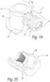
- Figure 19 represents a variant, wherein the second component consists of two loose parts 40-41, which can be snapped into each other by means of snap-on means 42 or the like around the first part 12.
- Figure 20 represents one loose part 40 thereof. Both loose parts can be identical. It is clear that this pre-mounting can take place during manufacture and thus does not have to be performed by the user.
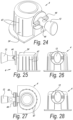
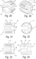
- connection device 1 In figures 21 to 36 , a variant of the connection device 1 is represented.
- connection device 1 comprises a first connection portion 6 and a second connection portion 9.
- first connection portion 6 and the second connection portion 9 extend according to respective longitudinal axes L1-L2, wherein these longitudinal axes preferably extend according to mutually different directions and mutually are situated at an angle of 90 degrees or substantially 90 degrees.
- the embodiment of figures 21 to 36 differs from the embodiment of figures 1 to 6 in a limited number of respects only.
- the spreading system 7 is characterized by a spreading direction S which extends transverse in respect to the longitudinal axis L2 of the second connection portion 9.
- the spreading system 7, however, is characterized by a spreading direction S which, as indicated in figure 16 , extends substantially parallel to the longitudinal axis of the second connection portion 9.
- forces may occur which are of such a nature that the first part 12 is subjected to lateral forces, for example, tilting forces, and said part comes to sit in the gap 18, as a result of which the quality of the connection may be jeopardized.
- the aforementioned difference manifests itself, amongst others, due to the fact that the oval-shaped element 14 in figure 1 is directed horizontal with the longest axis of the oval shape, whereas, on the contrary, in figure 21 this longest axis is vertical.
- connection devices 1 preferably are provided with a tensioning system with which a tensioning can be effected of the second connection portion 9 towards the second part 13 of the first attachment portion 6, preferably a tensioning according to an axial direction of the first attachment portion 6, wherein said tensioning system preferably is integrated into said spreading system 7.
- means 43 which, when tensioning the first connection portion 6, thus, when activating it, allow that the second connection portion 9 is displaced towards the second part 13 of the first connection portion 6, with the advantage that the furniture parts 2-3 are also drawn towards each other and thereby preferably are tensioned against each other.
- these means are formed by the deformation parts 30 which, when the whole is tensioned, are compressed and/or deformed and/or pushed away.
- these last-mentioned means 43 are formed by portions which rotate along each other and, during tensioning, can engage deeper in each other.
- these means 43 also are designed such that with said rotation a perceptible final position is provided in which the spreading effect of the spreading system 7 preferably is maximum.
- said portions are formed by the represented protrusions 44, on the one hand, and the narrow edge 46, which is provided with countersunk parts 45, of the second part 13, on the other hand.
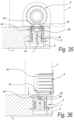
- the working is illustrated in figures 35 and 36 and is substantially as follows. In figure 35 , the initial condition is represented in which a tensioning has not yet been realized.
- connection device 1 is provided with the first connection portion 6 in the recess 8, whereas the furniture part 3 is slid on the body 24 of the second connection portion 9 and still has to be rotated into the final position.
- Figure 35 thus represents a condition in which the furniture parts 2 and 3 are situated in a mutual position as in figure 18 .
- the protrusions 44 are located against the not-countersunk portions of the edge 46.
- a tensioning is realized in a manner analogous to that of figures 15 and 16 .
- the conical shape of the first part 12 not only a radial tensioning is obtained, but also an axial tensioning, while the protrusions 44 rotate over the edge 46.
- this axial tensioning has as a consequence that the second connection portion 9 and the furniture part 3 attached thereto is drawn towards the furniture part 2, whereby a possible play among the furniture parts is removed.
- connection devices 1 preferably are provided with retaining means for retaining the second connection portion 9 in the respective furniture part 3, such that the connection portion 9 and the furniture part 2 cannot or less fast come loose according to the respective insertion direction.
- these retaining means simply can consist in that the second connection portion 9, and more particularly the body 24, cooperates with the recess 10 with a clamping fit.
- the use of a somewhat conical body 24, such that a clamping is obtained at the end of the insertion only, is recommended.
- these retaining means comprise clamping ribs 47.
- connection device preferably comprises positioning and/or blocking means which prevent or counteract a turning of the second part 13 in the respective recess 8 and/or provide in a positioning of the second part 13 in the recess, such before the connection device is activated, thus, before the first part is tensioned in the second part 13.
- these means are formed, amongst others, by the fact that the second part 13 is configured such that, in the initially mounted condition, it fits into the respective recess with a preferably slight clamping fit, wherein this second part 13 in the represented examples further is provided with a structure, in this case the aforementioned toothing 23, which provides for an engagement effect both in axial and in circumferential direction.
- FIG 37 a variant is represented wherein said means are formed in that the first connection portion 6, and preferably the second part 13 thereof, as well as the recess 8, are provided with mutually engaging portions 48-49, which, in a well-defined position, fit into each other.
- the represented example use is made of one portion 48 in the form of a protrusion and two portions 49 in the form of recesses in which the protrusion 48 can become seated.
- connection device 1 which comprises a blocking system 50 which locks the second connection portion 9 and the furniture part 3 with which it cooperates, in the mounted final position against rotation in respect to the other furniture part 2.
- the blocking system substantially is formed by a locking part 51 provided on the second connection portion 9, which locking part, in said final position, engages in a recess 52.
- said locking part 51 can be formed as an elastically bendable lip 53 with a protrusion 54 which is forced into the recess 52 by the elastic lip 53 when the protrusion 54 has been brought opposite to the recess 52 by rotation.
- the locking part 51 may or may not be made in one piece with any of the remaining components of the connection device 1.
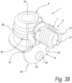
- the locking part 51 is made as a dismountable part and comprises a holder 55 with a portion 56 with which the holder is detachably provided around the body 24, as well as with a connection portion 57 to which the aforementioned lip 53 is attached.
- the holder 55 can also be provided with circumferential ribs, which may function as retaining means for the body 24. It is noted that the body 24, according to a not-represented embodiment, as such also can be provided with circumferential ribs, even when no blocking system 50 is applied.
- Figure 39 represents how the whole is mounted in a furniture part 3.
- the lip 53 is elastically bendable, as represented in dashed line.
- the blocking system 50 comprises a locking part 51 which cooperates directly with the furniture part 3 instead of with the actual connection device 1.
- the locking part 51 which also works as a kind of elastic lip, is provided with attachment portions 58 in the form of protrusions which fit into not represented openings, such as bore holes, in the end face of the furniture part 3, in such a manner as illustrated in figure 41 . It is clear that the working is analogous to the case of figure 40 .
- figure 42 specifically the engagement of the protrusion 54 in the recess 52 is represented.
- connection device 1 a particular embodiment of a connection device 1 according to the invention is represented.
- the aforementioned retaining means consist of a locking means 59 with hook-shaped locking parts 60 which engage behind an edge 61 on the furniture part 3 concerned, more particularly an edge in the form of a collar or the like.
- a locking means 59 in the form of an element 62 which is provided through an opening 63 in the second connection portion 9, on which, as aforementioned, one or more hook-shaped locking parts 60 are present, which can engage behind an edge 61 on the furniture part 3, as well as with a stop-forming part 63, which retains the second connection portion in the mounted position.
- the locking means 59 comprises a part 65 which can be inserted from the outside, preferably in the form of a plug, which can force and/or hold the locking parts 60 in a locking position. On the part 65 in its turn locking parts can be present for holding it in place after mounting, which locking parts in the example are formed by a recess 66 which can cooperate with edges 67.
- the working of the locking means 59 can simply be deduced from figure 47 . It substantially consists in that, after the second connection portion 9 is provided in the furniture part 3, this is retained in the respective opening by pushing the element 62 through the opening 63, as well as providing the part 65 in the element 62, all this until the locking parts 60 engage behind the edge 61.
- the edge 61 is formed by a circular collar.
- any edge or collar can be taken into account. So, for example, such collar may also be obtained by providing a groove 68 in the end face of the furniture part 3, said groove being made continuous, of which groove only a portion is indicated schematically in figure 47 .
- the production of such straight groove is considerably simpler than the production of a circular undercut.
- connection device 1 can consist of any suitable material, wherein whether or not different materials are applied for the respective components.
- the first component 4 shall be made of metal, whereas the second component 5 and the possible other component parts consist of synthetic material.
- connection device can be applied, for example, for interconnecting actual furniture parts, such as panels, posts and the like, as well as for attaching a fitting component, such as, for example, a rail for a drawer or a hinge, against a wall or the like.
- the second connection portion then can be made as a knob or wing nut which can be rotated for activating the spreading effect.
- the invention also relates to a method for mounting a piece of furniture, more particularly for attaching two furniture parts to each other, with the characteristic that the basic technique described by means of figure 18 is applied.
- said second component or thus the spreadable part, generally can be made such that it can be fixedly engaged on the first component, such that both components stay together prior to the application of the connection device 1 and can be marketed in joined condition.
- the second component may also adopt various forms. It is clear that it does not necessarily have to be made as a split body, but that this component can also be made, for example, as a continuous, for example, tube-shaped, body, for example, consisting of synthetic material, which can be simply spread radially open by means of a suitable cooperation with the first part.
- the term "spreading system” must be interpreted in a broad sense and in fact comprises any system with which a tensioning effect can be realized in a recess.
- figure 16 schematically a substantial spreading is represented; however, in reality this may also relate exclusively to a radial tensioning.
- the second part 13 is provided in the recess 8 with, for example, a slight clamping and that thus the subsequent spreading is very small and almost zero and substantially manifests itself as a radial pressing-on towards the outside.
- the fact that the mutual rotation between the first part and the second part, in function of the realized mutual angle position, effects a spreading effect means, in the broadest sense, that there are at least two angle positions, wherein at least in one position a more spread or tensioned condition of the spreading system is obtained than in the other position.
- connection device as well as the application thereof in a piece of furniture, can be realized according to various variants without leaving the scope of the invention, as defined by the appended claims.
Landscapes
- Engineering & Computer Science (AREA)
- General Engineering & Computer Science (AREA)
- Mechanical Engineering (AREA)
- Furniture Connections (AREA)
- Connection Of Plates (AREA)
Claims (15)
- Verbindungsvorrichtung für zwei miteinander zu verbindende Möbelteile,die einen ersten Verbindungsabschnitt (6) umfasst, der zumindest als ein Spreizsystem (7) realisiert ist und der dazu bestimmt ist, in einer Vertiefung (8) in einem ersten Möbelteil (2) vorgesehen zu werden,die einen zweiten Verbindungsabschnitt (9) umfasst, der dazu bestimmt ist, sich außerhalb der Vertiefung (8) zu erstrecken, um auf diese Weise mit einem zweiten Möbelteil (3) zusammenzuwirken,wobei die Verbindungsvorrichtung einen Aktivierungsmechanismus (11) zum Aktivieren des Spreizsystems (7) umfasst,wobei der zweite Verbindungsabschnitt (9) als ein Einsatzteil, insbesondere als ein Einsatzkörper, ausgebildet ist, wobei der zweite Verbindungsabschnitt (9) zum Einsetzen in eine Vertiefung (10) in dem zweiten Möbelteil (3) vorgesehen ist,wobei der zweite Verbindungsabschnitt (9) ein im Wesentlichen zylindrischer Körper ist, der eine abgerundete oder geneigte obere Kante (25) aufweist oder leicht konisch ausgebildet ist,wobei sowohl der erste Verbindungsabschnitt (6) als auch der zweite Verbindungsabschnitt (9) als Einsatzabschnitte hergestellt sind, die jeweils durch eine zugehörige Einsetzrichtung (R1, R2) gekennzeichnet sind, wobei die Einsetzrichtungen (R1-R2) sich quer zueinander befinden und sich vorzugsweise senkrecht oder nahezu senkrecht zueinander erstrecken,wobei das Spreizsystem (7) mindestens zwei gegenseitig drehbare Teile, einen ersten Teil (12) bzw. einen zweiten Teil (13), umfasst, wobei die gegenseitige Drehung davon, in Abhängigkeit von der realisierten gegenseitigen Winkelposition eine Spreizwirkung bewirkt, und wobei der Aktivierungsmechanismus (11) so ausgebildet ist, dass einer der zueinander drehbaren Teile mit dem zweiten Verbindungsabschnitt (9) oder mit einer Komponente davon verbunden ist, so dass der Aktivierungsmechanismus mittels einer an dem zweiten Verbindungsabschnitt (9) ausgeführte Drehung aktiviert werden kann,und wobei die oben genannte Drehung an dem zweiten Verbindungsteil (9) eine Drehung des ersten Teils (12) des Spreizsystems aufbringt;wobei der erste Verbindungsabschnitt (6) und der zweite Verbindungsabschnitt (9) sich jeweils entlang einer Längsachse (L1-L2) erstrecken, wobei diese Längsachsen sich in verschiedene gegenseitige Richtungen erstrecken und unter einem Winkel von 90 Grad oder im Wesentlichen 90 Grad zueinander stehen,und wobei das Spreizsystem eine erste Position, in der keine erzwungene Spreizung oder eine minimale erzwungene Spreizung vorliegt, und eine zweite Position, in der eine maximale erzwungene Spreizung vorhanden ist, einnehmen kann, und dass das Betätigungssystem derart ausgestaltet ist, dass das Spreizsystem mit einer gegenseitigen Verdrehung von weniger als einer halben Umdrehung, und vorzugsweise mit ca. einer Vierteldrehung, von der ersten in die zweite Position, bewegt werden kann, und dass der zweite Verbindungsabschnitt (9) so ausgestaltet ist, dass nach dem Einsetzen des zweiten Verbindungsabschnitts (9) in eine Vertiefung (10) eines zweiten Möbelteils (2) der Spreizmechanismus (7) durch Drehen des zweiten Möbelteils in Bezug auf das erste Möbelteil aktiviert werden kann;wobei die Drehachse der mindestens zwei gegeneinander drehbaren Teile senkrecht oder nahezu senkrecht zur Achse des im Wesentlichen zylindrischen Körpers liegt.
- Verbindungsvorrichtung, wobei die Achse des im Wesentlichen zylindrischen Körpers (24) sich unter einem Winkel von 90 Grad oder im Wesentlichen 90 Grad aus dem ersten Verbindungsvorrichtung (6) erstreckt.
- Verbindungsvorrichtung nach einem der vorhergehenden Ansprüche, wobei der im wesentlichen zylindrische Körper (24) hohl ausgebildet ist.
- Verbindungsvorrichtung nach einem der vorhergehenden Ansprüche, wobei der Körper (24) eine Kante (27) aufweist, die einen Anschlag bildet, die zu der Begrenzung der Einsatzbewegung ausgebildet ist.
- Verbindungsvorrichtung nach einem der vorhergehenden Ansprüche, dadurch gekennzeichnet, dass sie Rückhaltemittel umfasst, die dazu bestimmt sind, dass sie den zweiten Verbindungsabschnitt (9) in dem jeweiligen Möbelteil (3) halten.
- Verbindungsvorrichtung nach Anspruch 5, dadurch gekennzeichnet, dass die Rückhaltemittel nach einer oder mehreren der folgenden Möglichkeiten ausgeführt sind:- als Spannmittel;- als Klemmmittel in Form von Klemmrippen (47), wobei die Klemmrippen (47) vorzugsweise axial in Bezug auf den zweiten Verbindungsabschnitt (9) ausgerichtet sind;- als ein Verriegelungsmittel (59);- als ein Verriegelungmittel (59), das einen oder mehrere hakenförmigen Verriegelungsteilen (60) umfasst, die hinter eine Kante (61) an dem jeweiligen Möbelteil (3), wie z.B. einen Kragen oder dergleichen, greifen;- als ein Verriegelungsmittel (59) in Form eines Elements (62), das durch eine Öffnung (63) in dem zweiten Verbindungsabschnitt (9) hindurch vorgesehen ist, an dem, wie bereits erwähnt, ein oder mehrere hakenförmige Verriegelungsteile (60) vorhanden sind, die hinter eine Kante (61) an dem Möbelteil (3) greifen können, und das einen anschlagbildenden Teil (64) umfasst, der den zweiten Verbindungsabschnitt (9) in der montierten Position festhält;- als ein Verriegelungsmittel (59) wie im vorhergehenden Absatz, das einen von außen einsetzbaren Teil (65), beispielsweise in Form eines Stopfens umfasst, der die Verriegelungsteile in eine Verriegelungsposition drückt und/oder hält.
- Verbindungsvorrichtung nach einem der vorhergehenden Ansprüche, dadurch gekennzeichnet, dass sie Positionierung- und/oder Blockiermittel aufweist, die eine Drehung des zweiten Teils (13) in der jeweiligen Vertiefung (8) verhindern oder entgegenwirken und/oder eine Positionierung des zweiten Teils (13) in der Vertiefung bereitstellen.
- Verbindungsvorrichtung nach Anspruch 7, dadurch gekennzeichnet, dass die jeweiligen Mittel mindestens eine der folgenden Möglichkeiten umfassen:- der zweite Teil (13) ist so gestaltet, dass er mit Klemmsitz in die jeweilige Vertiefung (8) passt;- der zweite Teil (13) ist mit einer Struktur, wie z. B. Rippen und/oder einer Verzahnung (23) versehen, die für einen Eingriffseffekt sorgen;- der erste Verbindungsabschnitt (6) und vorzugsweise der zweite Teil (13) davon, sowie die Vertiefung (8) sind mit ineinander greifenden Abschnitten (48-49) versehen, die in einer bestimmten Position ineinander passen.
- Verbindungsvorrichtung nach einem der vorhergehenden Ansprüche, wobei der erste Teil (12) des Spreizsystems einstückig mit dem zweiten Verbindungsabschnitt (9) ausgebildet ist.
- Verbindungsvorrichtung nach einem der vorhergehenden Ansprüche, dadurch gekennzeichnet dass der erste Teil (12) des Spreizsystems (7) aus einem Element (14) mit hinsichtlich des Durchmessers variablen Abmessungen, insbesondere einem Nocken, besteht, während der zweite Teil (23) aus einem spreizbaren Körper (15) besteht, der an dem Umfang davon vorhanden ist.
- Verbindungsvorrichtung nach Anspruch 10, dadurch gekennzeichnet, dass der erste Teil (12) einen nicht-zylindrischen, vorzugsweise jedoch einen runden, insbesondere einen elliptischen oder ovalen Querschnitt aufweist.
- Verbindungsvorrichtung nach Anspruch 10 oder 11, dadurch gekennzeichnet, dass der erste Teil (12) zudem hin zu dem zweiten Verbindungsabschnitt hin sich konisch verjüngt hergestellt ist, um eine Spannkraft auch in der axialen Richtung zu realisieren.
- Verbindungsvorrichtung nach einem der vorhergehenden Ansprüche, dadurch gekennzeichnet, dass der zweite Teil (13) des Spreizsystems als ein spreizbarer hülsenförmiger Körper (15) realisiert ist, der aus einem oder mehreren Teilen bestehen kann oder nicht und der vorzugsweise aus einer geteilten Buchse und insbesondere aus einer in zwei Teile (20-21) geteilten Buchse besteht.
- Verbindungsvorrichtung nach einem der vorhergehenden Ansprüche, dadurch gekennzeichnet, dass sie mit einem Spannsystem bereitgestellt ist, mit dem eine Spannung des zweiten Verbindungsabschnitts (9) in Richtung des zweiten Teils (13) des ersten Verbindungsabschnitts (6), vorzugsweise eine Spannung gemäß einer axialen Richtung des ersten Verbindungsabschnitts (6), bewirkt werden kann, wobei dieses Spannsystem vorzugsweise in das Spreizsystem (7) integriert ist.
- Möbelstück, dadurch gekennzeichnet, dass es mindestens zwei Möbelteile umfasst, die mittels einer Verbindungsvorrichtung (1) nach einem der vorhergehenden Ansprüche miteinander verbunden sind.
Applications Claiming Priority (3)
| Application Number | Priority Date | Filing Date | Title |
|---|---|---|---|
| US201261700092P | 2012-09-12 | 2012-09-12 | |
| PCT/IB2013/058486 WO2014041498A1 (en) | 2012-09-12 | 2013-09-12 | Connection device for two furniture parts to be connected to each other, as well as piece of furniture which uses such connection device |
| EP13799370.5A EP2895752B1 (de) | 2012-09-12 | 2013-09-12 | Möbelstück mit einer verbindungsvorrichtung |
Related Parent Applications (2)
| Application Number | Title | Priority Date | Filing Date |
|---|---|---|---|
| EP13799370.5A Division EP2895752B1 (de) | 2012-09-12 | 2013-09-12 | Möbelstück mit einer verbindungsvorrichtung |
| EP13799370.5A Division-Into EP2895752B1 (de) | 2012-09-12 | 2013-09-12 | Möbelstück mit einer verbindungsvorrichtung |
Publications (2)
| Publication Number | Publication Date |
|---|---|
| EP3907413A1 EP3907413A1 (de) | 2021-11-10 |
| EP3907413B1 true EP3907413B1 (de) | 2024-11-06 |
Family
ID=49709767
Family Applications (2)
| Application Number | Title | Priority Date | Filing Date |
|---|---|---|---|
| EP21179578.6A Active EP3907413B1 (de) | 2012-09-12 | 2013-09-12 | Verbindungsvorrichtung für zwei miteinander zu verbindende möbelteile sowie möbel mit solch einer verbindungsvorrichtung |
| EP13799370.5A Active EP2895752B1 (de) | 2012-09-12 | 2013-09-12 | Möbelstück mit einer verbindungsvorrichtung |
Family Applications After (1)
| Application Number | Title | Priority Date | Filing Date |
|---|---|---|---|
| EP13799370.5A Active EP2895752B1 (de) | 2012-09-12 | 2013-09-12 | Möbelstück mit einer verbindungsvorrichtung |
Country Status (5)
| Country | Link |
|---|---|
| US (1) | US9939001B2 (de) |
| EP (2) | EP3907413B1 (de) |
| CN (1) | CN104603476B (de) |
| DK (1) | DK2895752T3 (de) |
| WO (1) | WO2014041498A1 (de) |
Families Citing this family (14)
| Publication number | Priority date | Publication date | Assignee | Title |
|---|---|---|---|---|
| BE1022574B1 (nl) * | 2014-01-23 | 2016-06-08 | Unilin Bvba | Verbindingsinrichting en verbindingssysteem voor twee met elkaar te verbinden meubeldelen, alsmede meubel dat van een dergelijke verbindingsinrichting of een dergelijk verbindingssysteem gebruik maakt |
| SE538755C2 (en) * | 2015-02-27 | 2016-11-08 | Ikea Supply Ag | Furniture joint |
| AT517612B1 (de) * | 2015-10-09 | 2017-03-15 | Blum Gmbh Julius | Möbelbeschlag |
| DE202015008847U1 (de) * | 2015-12-22 | 2017-03-23 | Grass Gmbh | Befestigungsvorrichtung |
| CN105972019A (zh) * | 2016-07-04 | 2016-09-28 | 廊坊市如果电子商务有限公司 | 模块化家具拼接固定件 |
| DE102016119629A1 (de) | 2016-10-14 | 2018-04-19 | Wolfgang Held | Verbindungsvorrichtung |
| AT519915B1 (de) * | 2017-05-11 | 2020-11-15 | Blum Gmbh Julius | Dübel zum Befestigen von Beschlagteilen |
| AT17670U1 (de) * | 2017-10-11 | 2022-10-15 | Manuel Dietrich | Verbindungsvorrichtung |
| AT520913A1 (de) | 2018-02-01 | 2019-08-15 | Blum Gmbh Julius | Möbelbeschlag |
| WO2020194417A1 (ja) * | 2019-03-25 | 2020-10-01 | 彪 三木 | 連結具及び連結具用工具 |
| WO2020226574A2 (en) * | 2019-04-18 | 2020-11-12 | S.p.s. Intertech Co., Ltd. | A locking device for knockdown furniture |
| DE202020106305U1 (de) * | 2020-11-04 | 2020-11-18 | Häfele Berlin Gmbh & Co Kg | Aufdopplungsbeschlag und zugehörige Anordnung mit zwei aufgedoppelten Platten |
| MX2021011602A (es) * | 2021-09-23 | 2023-03-24 | Eduardo Calderon Abad | Tejido plastico de ensamble rotativo. |
| US20240384740A1 (en) * | 2023-05-17 | 2024-11-21 | Brian Fulton | Bracket for connecting furniture parts at right angles |
Family Cites Families (23)
| Publication number | Priority date | Publication date | Assignee | Title |
|---|---|---|---|---|
| GB1044473A (en) * | 1964-05-07 | 1966-09-28 | Ft Products Ltd | Improvements in and relating to fasteners |
| DE2546751A1 (de) * | 1975-10-18 | 1977-04-21 | Heinze Fa R | Beschlag zum loesbaren verbinden zweier bauteile, insbesondere zum loesbaren verbinden zweier senkrecht aufeinanderstossener plattenfoermiger bauteile |
| DE2546749A1 (de) * | 1975-10-18 | 1977-04-28 | Heinze Fa R | Beschlag zum loesbaren verbinden zweier bauteile, insbesondere zweier senkrecht aufeinanderstossender plattenfoermiger bauteile |
| DE2548527C3 (de) * | 1975-10-30 | 1979-09-27 | Fa. Richard Heinze, 4900 Herford | Beschlag zum lösbaren Verbinden zweier senkrecht aufeinanderstoßender Bauteile |
| FR2360780A1 (fr) * | 1976-01-13 | 1978-03-03 | Ceresoli Jean Marie | Dispositif de liaison pour elements de mobilier |
| FR2445461A3 (fr) * | 1978-12-26 | 1980-07-25 | Spinelli Giuseppe | Dispositif de jonction pour assemblage de panneaux employes pour la realisation de meubles |
| GB2076104A (en) * | 1980-05-03 | 1981-11-25 | Hettich Paul & Co | Fitting for connecting two panels |
| IT233424Y1 (it) * | 1994-05-13 | 2000-01-28 | Ferrari Franco | Elemento di fissaggio per elementi di ferramenta |
| IT233517Y1 (it) * | 1994-06-21 | 2000-01-28 | Ferrari Franco | Assieme di vincolo a tassello con regolazione della posizione per elementi di ferramenta in particolare guide per cassetti |
| IT237028Y1 (it) * | 1995-07-12 | 2000-08-31 | Ferrari Franco | Gruppo di fissaggio perfezionato per il fissaggio rapido dielementi di ferramenta ed elemento di ferramenta con un tale |
| US5823700A (en) * | 1996-09-18 | 1998-10-20 | Bush Industries, Inc. | Drawer front fastener |
| DE29721068U1 (de) * | 1997-11-27 | 1998-01-22 | Arturo Salice S.P.A., Novedrate, Como | Verbindungsbeschlag |
| DK0940587T3 (da) | 1998-02-17 | 2003-04-07 | Hettich Heinze Gmbh & Co Kg | Fastgørelsesanordning |
| CN2591308Y (zh) * | 2002-12-19 | 2003-12-10 | 汕头市升平区宏固标准件厂 | 一种连接件 |
| DE202004000199U1 (de) * | 2004-01-09 | 2004-04-15 | Ipeg Gmbh - Ingenieurdienstleistungen | Verbindungselement zum steck- und lösbaren sowie zugfesten Verbinden, insbesondere von zwei Platten |
| US20080084143A1 (en) * | 2006-10-06 | 2008-04-10 | Wen-Te Ho | Detachable fastener assembly |
| US7530651B2 (en) * | 2007-07-13 | 2009-05-12 | Grace Chance Enterprise Co., Ltd | RTA modular desktop cabinet |
| US7390069B1 (en) * | 2007-07-13 | 2008-06-24 | Grace Chance Enterprise Co., Ltd. | Ready-to-assemble modular desk |
| US20090206613A1 (en) * | 2008-02-15 | 2009-08-20 | Kenmark Industrial Co., Ltd. | Latch module |
| FR2927677B3 (fr) * | 2008-02-19 | 2010-03-12 | Kenmark Ind Co Ltd | Module d'assemblage verrouille |
| US20100202852A1 (en) * | 2009-02-09 | 2010-08-12 | Krause Steven T | No-tools panel coupler and insert |
| CN102116342A (zh) * | 2010-12-30 | 2011-07-06 | 曹蕾 | 一种旋转式家具连接件 |
| CN202391885U (zh) * | 2011-12-01 | 2012-08-22 | 福建惠乐家商贸有限公司 | 一种家具连接扣件 |
-
2013
- 2013-09-12 EP EP21179578.6A patent/EP3907413B1/de active Active
- 2013-09-12 WO PCT/IB2013/058486 patent/WO2014041498A1/en not_active Ceased
- 2013-09-12 EP EP13799370.5A patent/EP2895752B1/de active Active
- 2013-09-12 US US14/427,203 patent/US9939001B2/en active Active
- 2013-09-12 DK DK13799370.5T patent/DK2895752T3/da active
- 2013-09-12 CN CN201380046374.0A patent/CN104603476B/zh active Active
Also Published As
| Publication number | Publication date |
|---|---|
| CN104603476A (zh) | 2015-05-06 |
| EP2895752A1 (de) | 2015-07-22 |
| EP3907413A1 (de) | 2021-11-10 |
| DK2895752T3 (da) | 2021-11-08 |
| CN104603476B (zh) | 2017-03-08 |
| US20150252831A1 (en) | 2015-09-10 |
| WO2014041498A1 (en) | 2014-03-20 |
| US9939001B2 (en) | 2018-04-10 |
| EP2895752B1 (de) | 2021-08-18 |
Similar Documents
| Publication | Publication Date | Title |
|---|---|---|
| EP3907413B1 (de) | Verbindungsvorrichtung für zwei miteinander zu verbindende möbelteile sowie möbel mit solch einer verbindungsvorrichtung | |
| US5246322A (en) | Fastening element comprising a dowel-shaped sleeve | |
| US5642960A (en) | Fastening element | |
| EP3817625B1 (de) | Ablageboden für ein möbel oder haushaltsgerät | |
| CN107735582B (zh) | 用于家具和装饰物品的部件的具有最小可见度的连结装置 | |
| DE102007061926B4 (de) | Steckhalterung | |
| EP3114359B1 (de) | Vorrichtung zur verbindung eines strukturelements mit einem halteelement in einem abstand zueinander | |
| EP0611002A1 (de) | Schnell abnehmbarer Befestiger, insbesondere für Möbel | |
| DE10053200C2 (de) | Verbindungselement | |
| EP3111804B1 (de) | Versteckbare verbindungsvorrichtung für möbel | |
| EP3488114B1 (de) | Verbesserte vorrichtung zum verbinden von möbelteilen und einrichtungszubehör | |
| JP2012500949A (ja) | 公差補償機能を有する締結機構 | |
| WO2018069414A1 (de) | Verbindungsvorrichtung | |
| US9624957B2 (en) | Clip for fixing two members | |
| WO2016146272A1 (de) | Halteelement für einen tür- oder fensterdrücker und anordnung eines tür- oder fensterdrückers an einer aufnahmeöffnung eines fensterrahmens, eines türblatts oder dergleichen | |
| DE102012208084B3 (de) | Anlenk-Vorrichtung zum Anlenken eines Reibungs-Dämpfers an eine Waschmaschine | |
| EP3009692B1 (de) | Bewegbares möbelteil mit verbindungsvorrichtung | |
| CA2130681A1 (en) | Releasable clip | |
| EP1852304B1 (de) | Befestigungsanordnung mit lösbarer Verrastung | |
| EP3545202B1 (de) | Verbesserte vorrichtung zum verbinden von möbelteilen und möbelzubehör | |
| DE102014112308B4 (de) | Exzentereinheit und Verbinder | |
| EP0933481B1 (de) | Vorrichtung zur Befestigung eines Betätigungsorgans an einem Unterputzspülkasten | |
| BE1022574B1 (nl) | Verbindingsinrichting en verbindingssysteem voor twee met elkaar te verbinden meubeldelen, alsmede meubel dat van een dergelijke verbindingsinrichting of een dergelijk verbindingssysteem gebruik maakt | |
| WO2012150490A2 (en) | Coupling device for furniture and furnishing articles | |
| EP0856275A1 (de) | Befestigungsanordnung für einen Toilettensitz |
Legal Events
| Date | Code | Title | Description |
|---|---|---|---|
| PUAI | Public reference made under article 153(3) epc to a published international application that has entered the european phase |
Free format text: ORIGINAL CODE: 0009012 |
|
| STAA | Information on the status of an ep patent application or granted ep patent |
Free format text: STATUS: THE APPLICATION HAS BEEN PUBLISHED |
|
| AC | Divisional application: reference to earlier application |
Ref document number: 2895752 Country of ref document: EP Kind code of ref document: P |
|
| AK | Designated contracting states |
Kind code of ref document: A1 Designated state(s): AL AT BE BG CH CY CZ DE DK EE ES FI FR GB GR HR HU IE IS IT LI LT LU LV MC MK MT NL NO PL PT RO RS SE SI SK SM TR |
|
| B565 | Issuance of search results under rule 164(2) epc |
Effective date: 20211008 |
|
| STAA | Information on the status of an ep patent application or granted ep patent |
Free format text: STATUS: REQUEST FOR EXAMINATION WAS MADE |
|
| 17P | Request for examination filed |
Effective date: 20220331 |
|
| RBV | Designated contracting states (corrected) |
Designated state(s): AL AT BE BG CH CY CZ DE DK EE ES FI FR GB GR HR HU IE IS IT LI LT LU LV MC MK MT NL NO PL PT RO RS SE SI SK SM TR |
|
| STAA | Information on the status of an ep patent application or granted ep patent |
Free format text: STATUS: EXAMINATION IS IN PROGRESS |
|
| 17Q | First examination report despatched |
Effective date: 20230822 |
|
| RAP1 | Party data changed (applicant data changed or rights of an application transferred) |
Owner name: UNILIN, BV |
|
| GRAP | Despatch of communication of intention to grant a patent |
Free format text: ORIGINAL CODE: EPIDOSNIGR1 |
|
| STAA | Information on the status of an ep patent application or granted ep patent |
Free format text: STATUS: GRANT OF PATENT IS INTENDED |
|
| INTG | Intention to grant announced |
Effective date: 20240710 |
|
| GRAS | Grant fee paid |
Free format text: ORIGINAL CODE: EPIDOSNIGR3 |
|
| GRAA | (expected) grant |
Free format text: ORIGINAL CODE: 0009210 |
|
| STAA | Information on the status of an ep patent application or granted ep patent |
Free format text: STATUS: THE PATENT HAS BEEN GRANTED |
|
| P01 | Opt-out of the competence of the unified patent court (upc) registered |
Free format text: CASE NUMBER: APP_50873/2024 Effective date: 20240909 |
|
| AC | Divisional application: reference to earlier application |
Ref document number: 2895752 Country of ref document: EP Kind code of ref document: P |
|
| AK | Designated contracting states |
Kind code of ref document: B1 Designated state(s): AL AT BE BG CH CY CZ DE DK EE ES FI FR GB GR HR HU IE IS IT LI LT LU LV MC MK MT NL NO PL PT RO RS SE SI SK SM TR |
|
| REG | Reference to a national code |
Ref country code: GB Ref legal event code: FG4D |
|
| REG | Reference to a national code |
Ref country code: CH Ref legal event code: EP |
|
| REG | Reference to a national code |
Ref country code: DE Ref legal event code: R096 Ref document number: 602013086281 Country of ref document: DE |
|
| REG | Reference to a national code |
Ref country code: IE Ref legal event code: FG4D |
|
| REG | Reference to a national code |
Ref country code: NL Ref legal event code: FP |
|
| REG | Reference to a national code |
Ref country code: LT Ref legal event code: MG9D |
|
| PG25 | Lapsed in a contracting state [announced via postgrant information from national office to epo] |
Ref country code: HR Free format text: LAPSE BECAUSE OF FAILURE TO SUBMIT A TRANSLATION OF THE DESCRIPTION OR TO PAY THE FEE WITHIN THE PRESCRIBED TIME-LIMIT Effective date: 20241106 Ref country code: IS Free format text: LAPSE BECAUSE OF FAILURE TO SUBMIT A TRANSLATION OF THE DESCRIPTION OR TO PAY THE FEE WITHIN THE PRESCRIBED TIME-LIMIT Effective date: 20250306 Ref country code: PT Free format text: LAPSE BECAUSE OF FAILURE TO SUBMIT A TRANSLATION OF THE DESCRIPTION OR TO PAY THE FEE WITHIN THE PRESCRIBED TIME-LIMIT Effective date: 20250306 |
|
| PG25 | Lapsed in a contracting state [announced via postgrant information from national office to epo] |
Ref country code: FI Free format text: LAPSE BECAUSE OF FAILURE TO SUBMIT A TRANSLATION OF THE DESCRIPTION OR TO PAY THE FEE WITHIN THE PRESCRIBED TIME-LIMIT Effective date: 20241106 |
|
| REG | Reference to a national code |
Ref country code: AT Ref legal event code: MK05 Ref document number: 1739615 Country of ref document: AT Kind code of ref document: T Effective date: 20241106 |
|
| PG25 | Lapsed in a contracting state [announced via postgrant information from national office to epo] |
Ref country code: BG Free format text: LAPSE BECAUSE OF FAILURE TO SUBMIT A TRANSLATION OF THE DESCRIPTION OR TO PAY THE FEE WITHIN THE PRESCRIBED TIME-LIMIT Effective date: 20241106 |
|
| PG25 | Lapsed in a contracting state [announced via postgrant information from national office to epo] |
Ref country code: ES Free format text: LAPSE BECAUSE OF FAILURE TO SUBMIT A TRANSLATION OF THE DESCRIPTION OR TO PAY THE FEE WITHIN THE PRESCRIBED TIME-LIMIT Effective date: 20241106 |
|
| PG25 | Lapsed in a contracting state [announced via postgrant information from national office to epo] |
Ref country code: NO Free format text: LAPSE BECAUSE OF FAILURE TO SUBMIT A TRANSLATION OF THE DESCRIPTION OR TO PAY THE FEE WITHIN THE PRESCRIBED TIME-LIMIT Effective date: 20250206 |
|
| PG25 | Lapsed in a contracting state [announced via postgrant information from national office to epo] |
Ref country code: AT Free format text: LAPSE BECAUSE OF FAILURE TO SUBMIT A TRANSLATION OF THE DESCRIPTION OR TO PAY THE FEE WITHIN THE PRESCRIBED TIME-LIMIT Effective date: 20241106 Ref country code: LV Free format text: LAPSE BECAUSE OF FAILURE TO SUBMIT A TRANSLATION OF THE DESCRIPTION OR TO PAY THE FEE WITHIN THE PRESCRIBED TIME-LIMIT Effective date: 20241106 Ref country code: GR Free format text: LAPSE BECAUSE OF FAILURE TO SUBMIT A TRANSLATION OF THE DESCRIPTION OR TO PAY THE FEE WITHIN THE PRESCRIBED TIME-LIMIT Effective date: 20250207 |
|
| PG25 | Lapsed in a contracting state [announced via postgrant information from national office to epo] |
Ref country code: PL Free format text: LAPSE BECAUSE OF FAILURE TO SUBMIT A TRANSLATION OF THE DESCRIPTION OR TO PAY THE FEE WITHIN THE PRESCRIBED TIME-LIMIT Effective date: 20241106 |
|
| PG25 | Lapsed in a contracting state [announced via postgrant information from national office to epo] |
Ref country code: RS Free format text: LAPSE BECAUSE OF FAILURE TO SUBMIT A TRANSLATION OF THE DESCRIPTION OR TO PAY THE FEE WITHIN THE PRESCRIBED TIME-LIMIT Effective date: 20250206 |
|
| PG25 | Lapsed in a contracting state [announced via postgrant information from national office to epo] |
Ref country code: SM Free format text: LAPSE BECAUSE OF FAILURE TO SUBMIT A TRANSLATION OF THE DESCRIPTION OR TO PAY THE FEE WITHIN THE PRESCRIBED TIME-LIMIT Effective date: 20241106 |
|
| PG25 | Lapsed in a contracting state [announced via postgrant information from national office to epo] |
Ref country code: DK Free format text: LAPSE BECAUSE OF FAILURE TO SUBMIT A TRANSLATION OF THE DESCRIPTION OR TO PAY THE FEE WITHIN THE PRESCRIBED TIME-LIMIT Effective date: 20241106 |
|
| PG25 | Lapsed in a contracting state [announced via postgrant information from national office to epo] |
Ref country code: EE Free format text: LAPSE BECAUSE OF FAILURE TO SUBMIT A TRANSLATION OF THE DESCRIPTION OR TO PAY THE FEE WITHIN THE PRESCRIBED TIME-LIMIT Effective date: 20241106 |
|
| PG25 | Lapsed in a contracting state [announced via postgrant information from national office to epo] |
Ref country code: RO Free format text: LAPSE BECAUSE OF FAILURE TO SUBMIT A TRANSLATION OF THE DESCRIPTION OR TO PAY THE FEE WITHIN THE PRESCRIBED TIME-LIMIT Effective date: 20241106 |
|
| PG25 | Lapsed in a contracting state [announced via postgrant information from national office to epo] |
Ref country code: SK Free format text: LAPSE BECAUSE OF FAILURE TO SUBMIT A TRANSLATION OF THE DESCRIPTION OR TO PAY THE FEE WITHIN THE PRESCRIBED TIME-LIMIT Effective date: 20241106 |
|
| PG25 | Lapsed in a contracting state [announced via postgrant information from national office to epo] |
Ref country code: CZ Free format text: LAPSE BECAUSE OF FAILURE TO SUBMIT A TRANSLATION OF THE DESCRIPTION OR TO PAY THE FEE WITHIN THE PRESCRIBED TIME-LIMIT Effective date: 20241106 |
|
| PG25 | Lapsed in a contracting state [announced via postgrant information from national office to epo] |
Ref country code: IT Free format text: LAPSE BECAUSE OF FAILURE TO SUBMIT A TRANSLATION OF THE DESCRIPTION OR TO PAY THE FEE WITHIN THE PRESCRIBED TIME-LIMIT Effective date: 20241106 |
|
| REG | Reference to a national code |
Ref country code: DE Ref legal event code: R097 Ref document number: 602013086281 Country of ref document: DE |
|
| PG25 | Lapsed in a contracting state [announced via postgrant information from national office to epo] |
Ref country code: SE Free format text: LAPSE BECAUSE OF FAILURE TO SUBMIT A TRANSLATION OF THE DESCRIPTION OR TO PAY THE FEE WITHIN THE PRESCRIBED TIME-LIMIT Effective date: 20241106 |
|
| PLBE | No opposition filed within time limit |
Free format text: ORIGINAL CODE: 0009261 |
|
| STAA | Information on the status of an ep patent application or granted ep patent |
Free format text: STATUS: NO OPPOSITION FILED WITHIN TIME LIMIT |
|
| PGFP | Annual fee paid to national office [announced via postgrant information from national office to epo] |
Ref country code: DE Payment date: 20250929 Year of fee payment: 13 |
|
| 26N | No opposition filed |
Effective date: 20250807 |
|
| PGFP | Annual fee paid to national office [announced via postgrant information from national office to epo] |
Ref country code: NL Payment date: 20250926 Year of fee payment: 13 |
|
| PGFP | Annual fee paid to national office [announced via postgrant information from national office to epo] |
Ref country code: FR Payment date: 20250925 Year of fee payment: 13 |