EP3907334B1 - Arbeitsmaschine und arbeitsmaschinensteuerungsverfahren - Google Patents
Arbeitsmaschine und arbeitsmaschinensteuerungsverfahren Download PDFInfo
- Publication number
- EP3907334B1 EP3907334B1 EP20782694.2A EP20782694A EP3907334B1 EP 3907334 B1 EP3907334 B1 EP 3907334B1 EP 20782694 A EP20782694 A EP 20782694A EP 3907334 B1 EP3907334 B1 EP 3907334B1
- Authority
- EP
- European Patent Office
- Prior art keywords
- cylinder
- flow rate
- bucket
- drive command
- boom
- Prior art date
- Legal status (The legal status is an assumption and is not a legal conclusion. Google has not performed a legal analysis and makes no representation as to the accuracy of the status listed.)
- Active
Links
Images





Classifications
-
- E—FIXED CONSTRUCTIONS
- E02—HYDRAULIC ENGINEERING; FOUNDATIONS; SOIL SHIFTING
- E02F—DREDGING; SOIL-SHIFTING
- E02F3/00—Dredgers; Soil-shifting machines
- E02F3/04—Dredgers; Soil-shifting machines mechanically-driven
- E02F3/28—Dredgers; Soil-shifting machines mechanically-driven with digging tools mounted on a dipper- or bucket-arm, i.e. there is either one arm or a pair of arms, e.g. dippers, buckets
- E02F3/36—Component parts
- E02F3/42—Drives for dippers, buckets, dipper-arms or bucket-arms
- E02F3/43—Control of dipper or bucket position; Control of sequence of drive operations
- E02F3/431—Control of dipper or bucket position; Control of sequence of drive operations for bucket-arms, front-end loaders, dumpers or the like
-
- E—FIXED CONSTRUCTIONS
- E02—HYDRAULIC ENGINEERING; FOUNDATIONS; SOIL SHIFTING
- E02F—DREDGING; SOIL-SHIFTING
- E02F3/00—Dredgers; Soil-shifting machines
- E02F3/04—Dredgers; Soil-shifting machines mechanically-driven
- E02F3/28—Dredgers; Soil-shifting machines mechanically-driven with digging tools mounted on a dipper- or bucket-arm, i.e. there is either one arm or a pair of arms, e.g. dippers, buckets
- E02F3/283—Dredgers; Soil-shifting machines mechanically-driven with digging tools mounted on a dipper- or bucket-arm, i.e. there is either one arm or a pair of arms, e.g. dippers, buckets with a single arm pivoted directly on the chassis
-
- E—FIXED CONSTRUCTIONS
- E02—HYDRAULIC ENGINEERING; FOUNDATIONS; SOIL SHIFTING
- E02F—DREDGING; SOIL-SHIFTING
- E02F3/00—Dredgers; Soil-shifting machines
- E02F3/04—Dredgers; Soil-shifting machines mechanically-driven
- E02F3/28—Dredgers; Soil-shifting machines mechanically-driven with digging tools mounted on a dipper- or bucket-arm, i.e. there is either one arm or a pair of arms, e.g. dippers, buckets
- E02F3/34—Dredgers; Soil-shifting machines mechanically-driven with digging tools mounted on a dipper- or bucket-arm, i.e. there is either one arm or a pair of arms, e.g. dippers, buckets with bucket-arms, i.e. a pair of arms, e.g. manufacturing processes, form, geometry, material of bucket-arms directly pivoted on the frames of tractors or self-propelled machines
- E02F3/3405—Dredgers; Soil-shifting machines mechanically-driven with digging tools mounted on a dipper- or bucket-arm, i.e. there is either one arm or a pair of arms, e.g. dippers, buckets with bucket-arms, i.e. a pair of arms, e.g. manufacturing processes, form, geometry, material of bucket-arms directly pivoted on the frames of tractors or self-propelled machines and comprising an additional linkage mechanism
- E02F3/3411—Dredgers; Soil-shifting machines mechanically-driven with digging tools mounted on a dipper- or bucket-arm, i.e. there is either one arm or a pair of arms, e.g. dippers, buckets with bucket-arms, i.e. a pair of arms, e.g. manufacturing processes, form, geometry, material of bucket-arms directly pivoted on the frames of tractors or self-propelled machines and comprising an additional linkage mechanism of the Z-type
-
- E—FIXED CONSTRUCTIONS
- E02—HYDRAULIC ENGINEERING; FOUNDATIONS; SOIL SHIFTING
- E02F—DREDGING; SOIL-SHIFTING
- E02F3/00—Dredgers; Soil-shifting machines
- E02F3/04—Dredgers; Soil-shifting machines mechanically-driven
- E02F3/28—Dredgers; Soil-shifting machines mechanically-driven with digging tools mounted on a dipper- or bucket-arm, i.e. there is either one arm or a pair of arms, e.g. dippers, buckets
- E02F3/36—Component parts
- E02F3/42—Drives for dippers, buckets, dipper-arms or bucket-arms
- E02F3/422—Drive systems for bucket-arms, front-end loaders, dumpers or the like
-
- E—FIXED CONSTRUCTIONS
- E02—HYDRAULIC ENGINEERING; FOUNDATIONS; SOIL SHIFTING
- E02F—DREDGING; SOIL-SHIFTING
- E02F9/00—Component parts of dredgers or soil-shifting machines, not restricted to one of the kinds covered by groups E02F3/00 - E02F7/00
- E02F9/20—Drives; Control devices
- E02F9/22—Hydraulic or pneumatic drives
- E02F9/2203—Arrangements for controlling the attitude of actuators, e.g. speed, floating function
- E02F9/2214—Arrangements for controlling the attitude of actuators, e.g. speed, floating function for reducing the shock generated at the stroke end
-
- E—FIXED CONSTRUCTIONS
- E02—HYDRAULIC ENGINEERING; FOUNDATIONS; SOIL SHIFTING
- E02F—DREDGING; SOIL-SHIFTING
- E02F9/00—Component parts of dredgers or soil-shifting machines, not restricted to one of the kinds covered by groups E02F3/00 - E02F7/00
- E02F9/20—Drives; Control devices
- E02F9/22—Hydraulic or pneumatic drives
- E02F9/2221—Control of flow rate; Load sensing arrangements
- E02F9/2225—Control of flow rate; Load sensing arrangements using pressure-compensating valves
- E02F9/2228—Control of flow rate; Load sensing arrangements using pressure-compensating valves including an electronic controller
-
- E—FIXED CONSTRUCTIONS
- E02—HYDRAULIC ENGINEERING; FOUNDATIONS; SOIL SHIFTING
- E02F—DREDGING; SOIL-SHIFTING
- E02F9/00—Component parts of dredgers or soil-shifting machines, not restricted to one of the kinds covered by groups E02F3/00 - E02F7/00
- E02F9/20—Drives; Control devices
- E02F9/22—Hydraulic or pneumatic drives
- E02F9/2264—Arrangements or adaptations of elements for hydraulic drives
- E02F9/2271—Actuators and supports therefor and protection therefor
-
- E—FIXED CONSTRUCTIONS
- E02—HYDRAULIC ENGINEERING; FOUNDATIONS; SOIL SHIFTING
- E02F—DREDGING; SOIL-SHIFTING
- E02F9/00—Component parts of dredgers or soil-shifting machines, not restricted to one of the kinds covered by groups E02F3/00 - E02F7/00
- E02F9/20—Drives; Control devices
- E02F9/22—Hydraulic or pneumatic drives
- E02F9/2278—Hydraulic circuits
- E02F9/2296—Systems with a variable displacement pump
-
- E—FIXED CONSTRUCTIONS
- E02—HYDRAULIC ENGINEERING; FOUNDATIONS; SOIL SHIFTING
- E02F—DREDGING; SOIL-SHIFTING
- E02F9/00—Component parts of dredgers or soil-shifting machines, not restricted to one of the kinds covered by groups E02F3/00 - E02F7/00
- E02F9/08—Superstructures; Supports for superstructures
- E02F9/0841—Articulated frame, i.e. having at least one pivot point between two travelling gear units
-
- E—FIXED CONSTRUCTIONS
- E02—HYDRAULIC ENGINEERING; FOUNDATIONS; SOIL SHIFTING
- E02F—DREDGING; SOIL-SHIFTING
- E02F9/00—Component parts of dredgers or soil-shifting machines, not restricted to one of the kinds covered by groups E02F3/00 - E02F7/00
- E02F9/20—Drives; Control devices
- E02F9/2004—Control mechanisms, e.g. control levers
-
- E—FIXED CONSTRUCTIONS
- E02—HYDRAULIC ENGINEERING; FOUNDATIONS; SOIL SHIFTING
- E02F—DREDGING; SOIL-SHIFTING
- E02F9/00—Component parts of dredgers or soil-shifting machines, not restricted to one of the kinds covered by groups E02F3/00 - E02F7/00
- E02F9/20—Drives; Control devices
- E02F9/22—Hydraulic or pneumatic drives
- E02F9/2278—Hydraulic circuits
- E02F9/2285—Pilot-operated systems
-
- E—FIXED CONSTRUCTIONS
- E02—HYDRAULIC ENGINEERING; FOUNDATIONS; SOIL SHIFTING
- E02F—DREDGING; SOIL-SHIFTING
- E02F9/00—Component parts of dredgers or soil-shifting machines, not restricted to one of the kinds covered by groups E02F3/00 - E02F7/00
- E02F9/20—Drives; Control devices
- E02F9/22—Hydraulic or pneumatic drives
- E02F9/2278—Hydraulic circuits
- E02F9/2292—Systems with two or more pumps
Definitions
- the present invention relates to a work machine and a method for controlling a work machine.
- a wheel loader as an example of a work implement has a work implement with a bucket at the tip of the boom.
- a hydraulic cylinder for boom is provided between the vehicle body of the wheel loader and the boom, and the boom rotates in the vertical direction due to expansion and contraction of the hydraulic cylinder.
- a bell crank is attached to the boom, and a hydraulic cylinder for a bucket is provided between one end of the bell crank and the vehicle body. The other end of the bell crank is attached to the bucket by a rod.
- the hydraulic cylinder for the bucket extends, the bucket rotates in the tilt direction, and when the hydraulic cylinder for the bucket contracts, the bucket rotates in the dump direction (see, for example, JP 5717923 B1 ).
- the bucket reaches the tilt end or the dump end due to the configuration of the work implement linkage before the stroke of the cylinder for the bucket reaches the maximum or minimum value, so that, over the entire boom angle, the maximum stroke of the cylinder for the bucket does not corresponds to the tilt end and the minimum stroke of the cylinder for the bucket does not correspond to the dump end.
- the impact mitigation control at the tilt end or the dump end is performed based on a map in which the stroke end of the cylinder length in consideration of the bucket shape is defined with respect to the boom angle.
- An object of the present invention is to provide a work machine and a method for controlling a work machine capable of mitigating an impact at a tilt end or a dump end without considering a boom angle.
- a work machine of the present invention includes a boom, a work tool, a cylinder, a sub-link, an operating member, a control section and a detection section.
- the work tool is configured to drive with respect to the boom.
- the cylinder is configured to drive the work tool.
- the sub-link is attached to the boom and is configured to transmit the driving force of the cylinder to the work tool.
- the control section controls the cylinder based on a posture of the sub-link with respect to the boom.
- the operating member is configured for operating the work tool.
- the detection section is configured for detecting a stroke of the cylinder.
- the control section is configured to give a target cylinder drive command based on one of a first cylinder drive command based on difference between the posture of the sub-link and a limit posture of the sub-link and a second cylinder drive command based on difference between the stroke and an end position of the cylinder.
- the target cylinder drive command includes information on supplied flow rate of hydraulic fluid to the cylinder.
- each of the first cylinder drive command and the second cylinder drive command includes information on a limit flow rate for supplied flow rate of hydraulic fluid to the cylinder by operating the operating member, and the control section is configured to give the target cylinder drive command using a larger limit flow rate of both the first cylinder drive command and the second cylinder drive command, wherein a larger limit flow rate results in a smaller flow rate of the hydraulic fluid supplied to the cylinder.
- a method for controlling a work machine of the present invention includes a detection step and a control step.
- a stroke of a cylinder is detected.
- a target cylinder drive command is given based on one of a first cylinder drive command and a second cylinder drive command to control the cylinder, the first cylinder drive command being based on difference between a posture of a sub-link, which is configured to transmit driving force of the cylinder to a work tool configured to drive with respect to the boom, with respect to the boom and a limit posture of the sub-link, the second cylinder drive command being based on difference between the stroke and an end position of the cylinder, wherein the target cylinder drive command includes information on supplied flow rate of hydraulic fluid to the cylinder, each of the first cylinder drive command and the second cylinder drive command includes information on a limit flow rate for supplied flow rate of hydraulic fluid to the cylinder by operating an operating member for operating the work tool, and the control step involves giving the target cylinder drive command using a larger limit flow rate of both the first cylinder drive command and
- FIG. 1 is a schematic view showing the configuration of the wheel loader 1 of the present embodiment.
- the wheel loader 1 of the present embodiment includes a vehicle body 2 (an example of a vehicle body) and work implement 3.
- vehicle body 2 includes a vehicle body frame 10, a pair of front tires 4, a cab 5, an engine room 6, a pair of rear tires 7, and a control system 8 (see FIG. 3 ).
- the wheel loader 1 uses work implement 3 to perform earth and sand loading work and the like.
- the vehicle body frame 10 is a so-called articulated type, and includes a front frame 11, a rear frame 12, and a connecting shaft part 13.
- the front frame 11 is arranged in front of the rear frame 12.
- the connecting shaft part 13 is provided at the center in the vehicle width direction, and connects the front frame 11 and the rear frame 12 so as to be swingable to each other.
- the cab 5 is provided on the rear frame 12 and a driver's seat is arranged in the cab 5.
- the cab 5 is provided with an input/output device 50, a boom operating lever 61, a bucket operating lever 62, and the like, which will be described later.
- the pair of front tires 4 are attached to the left and right sides of the front frame 11. Further, a pair of rear tires 7 are attached to the left and right sides of the rear frame 12.
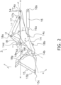
- FIG. 2 is an enlarged side view of work implement 3.
- the work implement 3 includes a boom 14, a bucket 15 (an example of a work tool), a boom cylinder 16, a bucket cylinder 17 (an example of an actuator), and a bell crank 18 (an example of a sub-link).
- One attachment part 14a of the boom 14 is rotatably attached to the front part of the front frame 11.
- the other attachment part 14b of the boom 14 is rotatably attached to the rear part of the bucket 15.
- the tip of the cylinder rod 16a of the boom cylinder 16 is rotatably attached to the attachment part 14c provided between the attachment part 14a and the attachment part 14b of the boom 14.
- the cylinder body of the boom cylinder 16 is rotatably attached to the front frame 11 at the attachment part 16b.
- the bell crank 18 includes a bell crank body 18e and a rod 18f.
- the attachment part 18a provided at one end of the bell crank body 18e is rotatably attached to the tip of the cylinder rod 17a of the bucket cylinder 17.
- One end of the rod 18f is rotatably attached to an attachment part 18b provided at the other end of the bell crank body 18e.
- the other end of the rod 18f is rotatably attached to the rear part of the bucket 15 at the attachment part 18g.
- the bell crank body 18e rotatably supported by a bell crank support 14d near the center of the boom 14 at the attachment part 18c (an example of a fourth mounting part) provided between the attachment part 18a (an example of a second mounting part) and the attachment part 18b (an example of a third mounting part).
- the cylinder body of the bucket cylinder 17 is rotatably attached to the front frame 11 at the attachment part 17b (an example of the first attachment part).
- the expansion and contraction force of the bucket cylinder 17 is converted into a rotary motion by the bell crank and transmitted to the bucket 15.
- the sub-link may include a quick coupler or the like in addition to the bell crank 18.
- the bucket 15 rotates with respect to the boom 14 to perform a tilt operation (see arrow J) and a dump operation (see arrow K).
- the tilt operation of the bucket 15 is an operation in which the bucket 15 tilts by the opening 15b and the claw 15c of the bucket 15 rotating toward the cab 5.
- the dump operation of the bucket 15 is the opposite of the tilt operation, and is an operation in which the bucket 15 tilts by the opening 15b and the claw 15c of the bucket 15 rotating toward so as to move away from the cab 5.
- the boom angle sensor 54 is provided on the attachment part 14a of the boom 14.
- the boom angle sensor 54 detects the boom angle (indicated by ⁇ a in the figure) between the center line L1 of the boom 14 and the horizontal line H, and outputs a detection signal.
- the center line L1 of the boom 14 is a line connecting the attachment part 14a and the attachment part 14b of the boom 14.
- the boom angle has a negative value when the center line L1 is inclined toward the road surface R (see FIG. 1 ) with respect to the horizontal line H.
- the bell crank angle sensor 55 is provided on the attachment part 18c of the bell crank 18.
- the bell crank angle sensor 55 detects the bell crank angle (indicated by ⁇ b in the figure) between the line L2 connecting the attachment part 18a and the attachment part 18c of the bell crank 18 and the center line L1 of the boom 14, and outputs the detection signal.
- the bell crank angle is an example of a posture of the bell crank 18.
- FIG. 3 is a view showing a control system 8 controlling operation of the work implement 3.
- the control system 8 controls the operation of work implement 3.
- the control system 8 includes a work implement hydraulic pump 21, a boom operating valve 22, a bucket operating valve 23, a pilot pump 24, a discharge circuit 25, an electromagnetic proportional control valve 26, a control device 27, and an EG (engine) control device 29.
- the work implement hydraulic pump 21 is driven by the engine 30 mounted in the engine room 6.
- the engine 30 is an internal combustion engine, and for example, a diesel engine is used.
- the output of the engine 30 is input to the PTO (power Take Off) 31, and then output to the work implement hydraulic pump 21 and the transmission 34.
- the work implement hydraulic pump 21 is driven by the engine 30 via the PTO 31 to discharge the hydraulic fluid.
- the input side of the clutch 32 is attached to the engine 30.
- the output side of the clutch 32 is attached to the torque converter (TC) 33.
- the output of the engine 30 is transmitted to the transmission 34 via the PTO 31.
- the transmission 34 transmits the output of the engine 30 transmitted via the PTO 31 to the front tire 4 and the rear tire 7, and the front tire 4 and the rear tire 7 are driven.
- HST Hydro Static Transmission
- electric drive and the like can be appropriately used.
- the discharge circuit 25 is an oil passage through which the hydraulic fluid passes, and is attached to a discharge port in which the work implement hydraulic pump 21 discharges the hydraulic fluid.
- the discharge circuit 25 is attached to the boom operating valve 22 and the bucket operating valve 23.
- the boom operating valve 22 and the bucket operating valve 23 are hydraulic pilot type operation valves.
- the boom operating valve 22 and the bucket operating valve 23 are attached to the vehicle body 2.
- the work implement hydraulic pump 21, the boom operating valve 22, the bucket operating valve 23, and the discharge circuit 25 form a parallel hydraulic circuit.
- the boom operating valve 22 is a 4-position switching valve that can be switched between an A position, a B position, a C position, and a D position.
- the boom 14 raises when the boom operating valve 22 is in the A position, the boom 14 holds the position neutrally when the boom operating valve 22 is in the B position, the boom 14 lowers when the boom operating valve 22 is in the C position, and D position is "floating".
- the bucket operating valve 23 is a three-position switching valve that can be switched between a E position, a F position, and a G position.
- the bucket 15 tilts (see arrow J in FIG. 2 ) when the bucket operating valve 23 is in the E position, the bucket 15 holds the position neutrally when the bucket operating valve 23 is in the F position, and the bucket 15 dumps (see arrow K in FIG. 2 ) when the bucket operating valve 23 is in the G position.
- the pilot pump 24 is attached to pilot pressure receiving parts of the boom operating valve 22 and pilot pressure receiving parts of the bucket operating valve 23 via the electromagnetic proportional control valve 26.
- the pilot pump 24 is connected to the PTO 31 and is driven by the engine 30.
- the pilot pump 24 supplies a hydraulic fluid of pilot pressure to the pilot pressure receiving parts 22R of the boom operating valve 22 and the pilot pressure receiving parts 23R of the bucket operating valve 23 via the electromagnetic proportional control valve 26.
- the electromagnetic proportional control valve 26 includes a boom lowering electromagnetic proportional control valve 41, a boom raising electromagnetic proportional control valve 42, a bucket dump electromagnetic proportional control valve 43, and a bucket tilt electromagnetic proportional control valve 44.
- the boom lowering electromagnetic proportional control valve 41 and the boom raising electromagnetic proportional control valve 42 are attached to each pilot pressure receiving parts 22R of the boom operating valve 22.
- the bucket dump electromagnetic proportional control valve 43 and the bucket tilt electromagnetic proportional control valve 44 are attached to each pilot pressure receiving parts 23R of the bucket operating valve 23.
- a command signal from the control device 27 to each solenoid proportional control valve is input to a solenoid command section 41S of the boom lowering electromagnetic proportional control valve 41, the solenoid command section 42S of the boom raising electromagnetic proportional control valve 42, the solenoid command section 43S of the bucket dump electromagnetic proportional control valve 43, and the solenoid command section 44S of the bucket tilt electromagnetic proportional control valve 44.
- the boom 14 is rotated upward or downward by operations of the boom lowering electromagnetic proportional control valve 41, the boom raising electromagnetic proportional control valve 42, the boom operating valve 22, and the boom cylinder 16.
- the bucket 15 is tilted and dumped by operation of the bucket dump electromagnetic proportional control valve 43, the bucket tilt electromagnetic proportional control valve 44, the bucket operating valve 23, and the bucket cylinder 17.
- the control system 8 is provided with the boom operating lever 61 and the bucket operating lever 62 operated by an operator.
- the boom operating lever 61 is a lever for operating the boom 14.
- a first potentiometer 63 for detecting the operation amount of the boom operating lever 61 is attached to the boom operating lever 61.
- the bucket operating lever 62 is a lever for operating the bucket 15.
- a second potentiometer 64 for detecting the operation amount of the bucket operating lever 62 is attached to the bucket operating lever 62.
- the detection signals of the first potentiometer 63 and the second potentiometer 64 are input to the input section 47 of the control device 27.
- the boom operating lever 61 and the bucket operating lever 62 may be PPC levers that directly drive the operating valve operating the cylinder with pilot pressure.
- the control device 27 includes, for example, a processing section 45 such as a CPU (Central Processing Unit), a storage section 46 such as a ROM (Read Only Memory), an input section 47, and an output section 48.
- a processing section 45 such as a CPU (Central Processing Unit)
- a storage section 46 such as a ROM (Read Only Memory)
- an input section 47 and an output section 48.
- the processing section 45 controls operation of the work implement 3 by executing a computer program.
- the processing section 45 is electrically connected to the storage section 46, the input section 47, and the output section 48.
- the processing section 45 reads information from the storage section 46 and writes information to the storage section 46.
- the processing section 45 receives information from the input section 47.
- the processing section 45 outputs information from the output section 48.
- the storage section 46 stores a computer program that controls operation of the work implement 3 and information used for controlling the work implement 3.
- the storage section 46 stores a computer program to execute a method for controlling the work machine, and the processing section 45 reads and executes this program.
- the storage section 46 stores the maximum and minimum values of the cylinder length (an example of the stroke) of the bucket cylinder 17 and the maximum and minimum values of the bell crank angle.
- the maximum and minimum values of the bell crank angle correspond to an example of limit postures.
- the maximum and minimum values of the cylinder length correspond to an example of end positions.
- the storage section 46 stores four tables.
- the first table is a table showing the limit flow rate of the hydraulic fluid to the bucket cylinder 17 set for the difference between the bell crank angle acquired from the bell crank angle sensor 55 and the maximum value of the bell crank angle.
- the second table is a table showing the limit flow rate of the hydraulic fluid to the bucket cylinder 17 set for the difference between the bell crank angle acquired from the bell crank angle sensor 55 and the minimum value of the bell crank angle.
- the third table is a table showing the limit flow rate of the hydraulic fluid to the bucket cylinder 17 set for the difference between the maximum value of the cylinder length of the bucket cylinder 17 and the cylinder length of the bucket cylinder 17 acquired from the boom angle sensor 54 and the bell crank angle sensor 55.
- the fourth table is a table showing the limit flow rate of the hydraulic fluid to the bucket cylinder 17 set for the difference between the minimum value of the cylinder length of the bucket cylinder 17 and the cylinder length of the bucket cylinder 17 acquired from the boom angle sensor 54 and the bell crank angle sensor 55.
- Detection signals are input to the input section 47 from the boom angle sensor 54, the bell crank angle sensor 55, the first potentiometer 63, and the second potentiometer 64.
- the processing section 45 acquires these detection signals and controls the operation of work implement 3.
- the cylinder length (indicated by La in FIG. 2 ) of the bucket cylinder 17 is obtained from the boom angle detected by the boom angle sensor 54 and the bell crank angle detected by the bell crank angle sensor 55.
- the control device 27 obtains the cylinder length of the boom cylinder 16 and the cylinder length of the bucket cylinder 17 by using the detected values of at least one of the boom angle sensor 54 and the bell crank angle sensor 55, and controls the operations of the boom 14 and the bucket 15.
- the output section 48 outputs drive commands to the solenoid command section 41S of the boom lowering electromagnetic proportional control valve 41, the solenoid command section 42S of the boom raising electromagnetic proportional control valve 42, the solenoid command section 43S of the bucket dump electromagnetic proportional control valve 43, and the solenoid command section 44S of the bucket tilt electromagnetic proportional control valve 44, and the input/output device 50.
- the processing section 45 gives a command value for operating the boom cylinder 16 to the solenoid command section 41S of the boom lowering electromagnetic proportional control valve 41 or the solenoid command section 42S of the boom raising electromagnetic proportional control valve 42, expands and contracts the boom cylinder 16, and raises and lowers the boom 14.
- the processing section 45 gives a command value for operating the bucket cylinder 17 to the solenoid command section 43S of the bucket dump electromagnetic proportional control valve 43 or the solenoid command section 44S of the bucket tilt electromagnetic proportional control valve 44, expands and contracts the bucket cylinder 17, and tilts or dumps the bucket 15.
- the input/output device 50 is provided inside the cab 5.
- the input/output device 50 is connected to both the input section 47 and the output section 48.
- the input/output device 50 includes an input device 51 and a display device 52.
- the operator can input a command value from the input device 51 to the control device 27.
- the display device 52 displays information on the status or the control of work implement 3.
- the input device 51 can use a touch panel or a push button type switch. As will be described later, by operating the input device 51, it is possible to display a calibration mode for calibrating the maximum value of the bell crank angle at the tilt end.
- mitigation stop control is performed at the tilt end and the dump end in order to mitigate the impact at the tilt end and the dump end.
- the control device 27 of the present embodiment performs mitigation stop control based on the bell crank angle and the stroke length of the bucket cylinder 17.
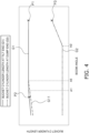
- FIG. 4 is a view showing a change (G1) in the bucket cylinder length at the tilt end with respect to the boom angle and a change (G2) in the bucket cylinder length at the dump end with respect to the boom angle.
- the vertical axis shows the bucket cylinder length
- the horizontal axis shows the boom angle.
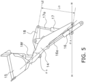
- FIG. 5 is a view showing a state in which the bucket reaches the tilt end at the maximum value of the bucket cylinder 17, and is a view showing an example of a work implement state in P1 of FIG. 4 .
- FIG. 5 shows a state in which the boom angle is the maximum value, the bucket cylinder 17 is fully extended, and the bucket 15 reaches the tilt end.
- FIG. 6 is a view showing an example of work implement 3 in P2 of FIG. 4 .
- the contact position is illustrated as C1, but the contact position at the mechanical limit changes depending on the configuration of the link of work implement3.
- the bucket 15 reaches the tilt end due to the mechanical limit of the link mechanism of work implement 3 from the minimum value to the angle A1, and the bucket 15 reaches the tilt end at the maximum value of the cylinder length of the bucket cylinder 17 from the angle A1 to the maximum value.
- the bucket reaches the dump end at the minimum value of the bucket cylinder 17 when the boom angle is from the minimum value to A2 degrees, but the bucket reaches the dump end before the cylinder length of the bucket cylinder 17 reaches the minimum value when the boom angle is from A2 degrees to the maximum value.
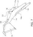
- FIG. 7 is a view showing an example of work implement 3 in P3 of FIG. 4 .
- the bell crank 18 is in contact with the frame part of the boom 14 arranged along the left-right direction, the bucket cylinder 17 cannot be contracted any more (see point C2).
- the bucket cylinder 17 reaches the tilt end at the minimum value of the cylinder length of the bucket cylinder 17 when the boom angle is from the minimum value to A2 degrees, and the bucket 15 reaches the dump end due to the mechanical limits of the link mechanism of the work implement 3 when the boom angle is from the predetermined value to the maximum value.
- the stroke length of the bucket cylinder 17 depends on the boom angle, but since the link mechanism reaches the mechanical limit, the bell crank angle is constant.
- FIG. 8 is a view in which the minimum value of the bucket cylinder length (G3), the maximum value of the bucket cylinder length (G4), the minimum value of the bell crank angle (G5), and the maximum value of the bell crank angle (G6) are added to the graph of Fig. 5 .
- the vertical axis shows the bucket cylinder length and the horizontal axis shows the boom angle.
- the maximum value G6 of the bell crank angle matches G1 in the region where the stroke length of the bucket cylinder 17 does not reach the maximum value.
- the minimum value G5 of the bell crank angle matches G2 in the region where the bucket cylinder length does not reach the minimum value.
- FIG. 9 is a view showing a graph in which the vertical axis of the graph of FIG. 8 is converted into a bell crank angle.
- the graph corresponding to G1 in FIG. 8 is illustrated as G1', and G1' shows the change in the bell crank angle at the tilt end with respect to the boom angle.
- the graph corresponding to G2 in FIG. 8 is illustrated as G2', and G2' shows the change in the bell crank angle at the dump end with respect to the boom angle.
- the end line G7 when the boom is lowered is drawn at A3 degree
- the end line G8 when the boom is raised is drawn at A4 degree.
- the bucket 15 reaches the tilt end at the maximum value G6 of the bell crank angle. Further, in the region where the stroke length of the bucket cylinder does not reach the minimum value at the dump end, the bucket 15 reaches the dump end at the minimum value G5 of the bell crank angle.
- G11 illustrated by a dotted line in FIG. 4 is a graph showing the bucket cylinder length at the tilt end when the bucket 15 is replaced with another one.
- the graph corresponding to G11 in FIG. 4 is illustrated as G11' in FIG. 9 .
- the bucket reaches the tilt end at the maximum value of the cylinder length of the bucket cylinder 17 when the boom angle is from the maximum value to A5 degrees, and the bucket reaches the tilt end before the cylinder length of the bucket cylinder 17 reaches the maximum value when the boom angle is from A5 degrees to the minimum value.
- the bucket 15 may be replaced with one having a different size by the operator.
- the mechanical limit also changes and the maximum value of the bell crank angle also changes, but as described above, the bell crank angle at the mechanical limit is constant. Therefore, when the bucket is replaced, it is possible to detect that the bucket 15 reaches the tilt end by obtaining the maximum value of the bell crank angle at the mechanical limit with calibration and using the maximum value and the bucket cylinder length. The calibration of the maximum value of the bell crank angle when the bucket is replaced will be described later.
- the dump end is determined by the shapes of the boom 14 and the bell crank 18 regardless of the bucket 15, so that it is not necessary to perform calibration and the dump end is determined by the design value.
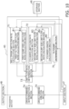
- FIG. 10 is a block diagram showing the configuration of the processing section 45 of the present embodiment.
- the processing section 45 includes a drive command creation section 70, a bell crank limit flow rate calculation section 71, a cylinder limit flow rate calculation section 72, a limit flow rate determination section 73, a drive command determination section 74, and a tilt/dump determination section 75.
- the drive command creation section 70 creates a drive command based on the operation of the boom operating lever 61 and the bucket operating lever 62 by the operator.
- the drive command creation section 70 acquires the operation amount signal of the boom operating lever 61 and the bucket operating lever 62 from the first potentiometer 63 and the second potentiometer 64 via the input section 47. Then, the drive command creation section 70 creates a drive command (an example of a target cylinder drive command) corresponding to the operation amount signal.
- This drive command is a command to drive the boom cylinder 16 or the bucket cylinder 17 so as to correspond to the operation amount signal, and defines the flow rate of the hydraulic fluid supplied to the boom cylinder 16 or the bucket cylinder 17.
- the drive command is a command so that the boom lowering electromagnetic proportional control valve 41, the boom raising electromagnetic proportional control valve 42, the bucket dump electromagnetic proportional control valve 43, or the bucket tilt electromagnetic proportional control valve 44 is set to the opening degree such that the hydraulic fluid of the flow rate corresponding to the operation amount flows.
- the tilt/dump determination section 75 determines whether the bucket 15 is operated to the tilt side or the dump side based on the detection signal from the second potentiometer 64 that detects the operation amount of the bucket operating lever 62.
- the tilt/dump determination section 75 transmits the determination result to the bell crank limit flow rate calculation section 71 and the cylinder limit flow rate calculation section 72.
- the bell crank limit flow rate calculation section 71 calculates the limit flow rate when driving the bucket cylinder 17 based on the bell crank angle acquired from the bell crank angle sensor 55 via the input section 47.
- the bell crank limit flow rate calculation section 71 includes a first tilt side limit flow rate calculation section 81 and a first dump side limit flow rate calculation section 82.
- the first tilt side limit flow rate calculation section 81 calculates the difference between the maximum value of the bell crank angle stored in the storage section 46 and the bell crank angle acquired by the bell crank angle sensor 55, and acquires the first tilt side limit flow rate (an example of the first cylinder drive command) from the first table stored in the storage section 46.
- the first table the smaller the difference (the closer the bell crank angle is to the maximum value), the larger the limit flow rate of the flow rate of hydraulic fluid supplied to the bucket cylinder 17 is set.
- the moving speed of the cylinder rod 17a of the bucket cylinder 17 is limited. That is, by limiting the moving speed of the bell crank 18 before reaching the maximum value of the bell crank angle, it is possible to stop gently when reaching the tilt end due to the mechanism limit.
- the first dump side limit flow rate calculation section 82 calculates the difference between the minimum value of the bell crank angle stored in the storage section 46 and the bell crank angle acquired by the bell crank angle sensor 55, and acquires the first dump side limit flow rate (an example of the first cylinder drive command) from the second table stored in the storage section 46.
- the second table the smaller the difference (the closer the bell crank angle is to the minimum value), the larger the limit flow rate of the flow rate of the hydraulic fluid supplied to the bucket cylinder 17 is set.
- the cylinder limit flow rate calculation section 72 includes a cylinder length calculation section 85, a second tilt side limit flow rate calculation section 83, and a second dump side limit flow rate calculation section 84.
- the cylinder length calculation section 85 calculates the cylinder length of the bucket cylinder 17 based on the boom angle acquired from the boom angle sensor 54 and the bell crank angle acquired from the bell crank angle sensor 55.
- the second tilt side limit flow rate calculation section 83 calculates the difference between the maximum value of the bucket cylinder length stored in the storage section 46 and the cylinder lengths calculated by the cylinder length calculation section 85, and acquires the second tilt side limit flow rate (an example of a second cylinder drive command) from the third table stored in the storage section 46.
- the third table the smaller the difference (the closer the cylinder length is to the maximum value), the larger the limit flow rate of the flow rate of the hydraulic fluid supplied to the bucket cylinder 17 is set.
- the second dump side limit flow rate calculation section 84 calculates the difference between the minimum value of the bucket cylinder length stored in the storage section 46 and the cylinder lengths calculated by the cylinder length calculation section 85, and acquires the second dump side limit flow rate (an example of the second cylinder drive command) from the fourth table stored in the storage section 46.
- the fourth table the smaller the difference (the closer the cylinder length is to the minimum value), the larger the limit flow rate of the flow rate of the hydraulic fluid supplied to the bucket cylinder 17 is set.
- the limit flow rate determination section 73 determines the larger flow rate of the first tilt side limit flow rate and the second tilt side limit flow rate as the limit flow rate for the drive command of the bucket cylinder 17. Further, when it is determined that the bucket 15 is operated to the dump side, the limit flow rate determination section 73 determines the larger flow rate of the first dump side limit flow rate and the second dump side limit flow rate as the limit flow rate for the drive command of the bucket cylinder 17.
- the limit flow rate for the closer one of the maximum value of the bell crank angle and the maximum value of the bucket cylinder length is adopted. Further, in the case of the operation of the bucket 15 to the dump side, the limit flow rate for the closer one of the minimum value of the bell crank angle and the minimum value of the bucket cylinder length is adopted.
- the larger limit flow rate means that the limited flow rate is large. For example, when the maximum flow rate is 100% and the limit flow rate is 40%, the hydraulic fluid is supplied to the bucket cylinder 17 at a flow rate of 60%. That is, the larger the limit flow rate, the smaller the flow rate of the hydraulic fluid supplied to the bucket cylinder 17.
- the limit flow rate increases as the bell crank angle approaches the maximum value or the bucket cylinder length approaches the maximum value, so that the moving speed of the bucket 15 slows down and it is possible to mitigate the impact at the tilt end.
- the limit flow rate increases as the bell crank angle approaches the minimum value or the bucket cylinder length approaches the minimum value, so that the moving speed of the bucket 15 slows down and it is possible to mitigate the impact at the dump end.
- the drive command determination section 74 creates a drive command of the maximum flow rate so as to keep the limit flow rate. That is, the limit flow rate is 40%, the flow rate can be supplied up to 60%, but when the flow rate of the hydraulic fluid supplied to the bucket cylinder 17 of the drive command created by the drive command creation section 70 is set to 80%, the drive command determination section 74 determines the drive command so that the flow rate is 60%. That is, the limit flow rate is the upper limit value of the flow rate that can be commanded to drive.
- the drive command determination section 74 control the bucket cylinder 17 with the created drive command (an example of a cylinder drive command).
- the opening degree of the bucket tilt electromagnetic proportional control valve 44 is narrowed in order to increase the limit flow rate of the hydraulic fluid when it is determined that the bucket 15 is operated to the tilt side. As a result, the pilot pressure can be lowered, so that the flow rate of the hydraulic fluid to the bucket cylinder 17 can be limited.
- the opening degree of the bucket dump electromagnetic proportional control valve 43 is narrowed in order to increase the limit flow rate of the flow rate of the hydraulic fluid when it is determined that the bucket 15 is operated to the dump side.
- the pilot pressure can be lowered, so that the flow rate of the hydraulic fluid to the bucket cylinder 17 can be limited.
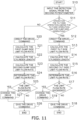
- FIG. 11 is a flow chart showing a method for controlling the work machine of the present embodiment.
- step S10 when the bucket operating lever 62 is operated by the operator, the second potentiometer 64 detects the operating amount of the bucket operating lever 62, and the detection signal is input to the input section 47 of the control device 27.
- step S11 the tilt/dump determination section 75 determines whether the bucket 15 is operated to the tilt side or the dump side based on the detection signal of the second potentiometer 64.
- step S11 when it is determined that the operation is on the tilt side, the control proceeds to step S12.
- step S12 the drive command creation section 70 creates a drive command for transmitting to the solenoid command section 44S of the bucket tilt electromagnetic proportional control valve 44 so that the flow rate of the hydraulic fluid based on the detection signal by the second potentiometer 64 is supplied to the bucket cylinder 17.
- the first tilt side limit flow rate calculation section 81 calculates the difference between the maximum value of the bell crank angle stored in the storage section 46 and the bell crank angle acquired from the bell crank angle sensor 55, and calculates the first tilt side limit flow rate from the first table stored in the storage section 46.
- step S14 the cylinder length calculation section 85 calculates the cylinder length of the bucket cylinder 17 based on the boom angle acquired from the boom angle sensor 54 and the bell crank angle acquired from the bell crank angle sensor 55.
- step S15 the second tilt side limit flow rate calculation section 83 calculates the difference between the maximum value of the bucket cylinder length stored in the storage section 46 and the cylinder length calculated by the cylinder length calculation section 85, and acquires the second tilt side limit flow rate from the third table.
- step S16 the limit flow rate determination section 73 determines the larger limit flow rate of the calculated first tilt side limit flow rate and the calculated second tilt side limit flow rate as the limit flow rate for the drive command to the bucket cylinder 17.
- step S17 the drive command determination section 74 determines whether or not the flow rate of the hydraulic fluid supplied to the bucket cylinder 17 by the drive command created by the drive command creation section 70 exceeds the limit flow rate.
- step S17 When it is determined in step S17 that the flow rate of the supplied hydraulic fluid does not exceed the limit flow rate, the control proceeds to step S18, and in step S18, the drive command created in step S12 is output from the output section 48 to the solenoid command section 44S of the bucket tilt electromagnetic proportional control valve 44.
- step S17 when it is determined in step S17 that the flow rate of the supplied hydraulic fluid exceeds the limit flow rate, the control proceeds to step S19, and in step S19, the drive command determination section 74 change the drive command so as to maximize the flow rate without exceeding the limit flow rate. Subsequently, in step S18, the changed drive command is output from the output section 48 to the solenoid command section 44S of the bucket tilt electromagnetic proportional control valve 44.
- step S11 when the tilt/dump determination section 75 determines that the operation is on the dump side based on the detection signal of the second potentiometer 64, the control proceeds to step S20.
- step S20 the drive command creation section 70 creates a drive command for transmitting to the solenoid command section 43S of the bucket dump electromagnetic proportional control valve 43 so that the flow rate of the hydraulic fluid based on the detection signal by the second potentiometer 64 is supplied to the boom cylinder 16 and the bucket cylinder 17.
- step S21 the first dump side limit flow rate calculation section 82 calculates the difference between the minimum value of the bell crank angle stored in the storage section 46 and the bell crank angle acquired from the bell crank angle sensor 55, and acquires the first dump side limit flow rate from the second table stored in the storage section 46.
- step S22 the cylinder length calculation section 85 calculates the cylinder length of the bucket cylinder 17 based on the boom angle acquired from the boom angle sensor 54 and the bell crank angle acquired from the bell crank angle sensor 55.
- step S23 the second dump side limit flow rate calculation section 84 calculates the difference between the minimum value of the bucket cylinder length stored in the storage section 46 and the cylinder length calculated by the cylinder length calculation section 85, and acquires the second dump side limit flow rate from the fourth table stored in the storage section 46.
- step S24 the limit flow rate determination section 73 determines the larger limit flow rate of the calculated first dump side limit flow rate and the calculated second dump side limit flow rate as the limit flow rate for the drive command to the bucket cylinder 17.
- step S25 the drive command determination section 74 determines whether or not the flow rate of the hydraulic fluid supplied to the bucket cylinder 17 by the drive command created by the drive command creation section 70 exceeds the limit flow rate.
- step S25 When it is determined in step S25 that the flow rate of the supplied hydraulic fluid does not exceed the limit flow rate, the control proceeds to step S26, and in step S26, the drive command created in step S20 is output from the output section 48 to the solenoid command section 43S of the bucket dump electromagnetic proportional control valve 43.
- step S25 when it is determined in step S25 that the flow rate of the supplied hydraulic fluid exceeds the limit flow rate, the control proceeds to step S27, and in step S27, the drive command determination section 74 change the drive command so as to maximize the flow rate without exceeding the limit flow rate. Subsequently, in step S26, the changed drive command is output from the output section 48 to the solenoid command section 43S of the bucket dump electromagnetic proportional control valve 43.
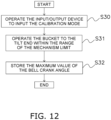
- FIG. 12 is a flow chart showing a method for calibrating the maximum value of the bell crank angle.
- step S30 the operator operates the input device 51 of the input/output device 50 to switch to the calibration mode screen of the maximum value of the bell crank angle.
- step S31 according to the instruction displayed on the display device 52 of the input/output device 50, the operator operates the bucket 15 to the tilt end (the position where the bucket 15 abuts on the boom 14) within the range of the mechanism limit where the bucket cylinder length does not reach the maximum value.
- the boom angle may be set to a value lower than A5 degrees and the bucket 15 may be operated to the tilt end.
- the bucket 15 since the boom angle that reaches the mechanism limit is not known, the bucket 15 may be tilted with the boom angle lowered as much as possible.
- step S32 the bell crank angle at the tilt end is stored as the maximum value of the bell crank angle.
- the maximum value of the stored bell crank angle is used in the method for controlling described above.
- the work machine and the method for controlling the work machine capable of mitigating an impact at a tilt end or a dump end without considering a boom angle.
Landscapes
- Engineering & Computer Science (AREA)
- Mining & Mineral Resources (AREA)
- Civil Engineering (AREA)
- General Engineering & Computer Science (AREA)
- Structural Engineering (AREA)
- Mechanical Engineering (AREA)
- Physics & Mathematics (AREA)
- Fluid Mechanics (AREA)
- Operation Control Of Excavators (AREA)
Claims (8)
- Arbeitsmaschine (1) umfassend:einen Ausleger (14);ein Arbeitswerkzeug (15), das so ausgebildet ist, dass es in Bezug auf den Ausleger (14) fährt;einen Zylinder (17), der für den Antrieb des Arbeitswerkzeugs (15) ausgebildet ist;ein Zwischenverbindungsglied (18), das am Ausleger (14) befestigt ist, wobei das Zwischenverbindungsglied (18) so ausgebildet ist, dass es die Antriebskraft des Zylinders (17) auf das Arbeitswerkzeug (15) überträgt; undeinen Steuerabschnitt (27), der so ausgebildet ist, dass er den Zylinder (17) auf der Grundlage einer Stellung des Zwischenverbindungsglieds (18) in Bezug auf den Ausleger (14) steuert;ein Betätigungselement (62) zum Betätigen des Arbeitswerkzeugs (15);einen Erfassungsabschnitt (54, 55) zum Erfassen eines Hubs des Zylinders,wobei der Steuerabschnitt (27) so ausgebildet ist, dass er einen Zielzylinder-Antriebsbefehl auf der Grundlage eines ersten Zylinder-Antriebsbefehls basierend auf der Differenz zwischen der Stellung des Zwischenverbindungsglieds (18) und einer Grenzstellung des Zwischenverbindungsglieds (18) oder eines zweiten Zylinder-Antriebsbefehls basierend auf der Differenz zwischen dem Hub und einer Endposition des Zylinders erteilt, dadurch gekennzeichnet, dassder Zielzylinder-Ansteuerungsbefehl Information über die Durchflussrate der Hydraulikflüssigkeit enthält, die dem Zylinder zugeführt wird,sowohl der erste Zylinderantriebsbefehl als auch der zweite Zylinderantriebsbefehl Informationen über eine Grenzdurchflussrate für die dem Zylinder durch Betätigung des Betätigungselements (62) zugeführte Durchflussrate von Hydraulikflüssigkeit enthält, undder Steuerabschnitt (27) so ausgebildet ist, dass er den Zielzylinder-Antriebsbefehl unter Verwendung einer größeren Grenzdurchflussrate sowohl des ersten als auch des zweiten Zylinder-Antriebsbefehls erteilt,wobei eine größere Grenzdurchflussrate zu einer geringeren Durchflussrate der dem Zylinder (17) zugeführten Hydraulikflüssigkeit führt.
- Arbeitsmaschine (1) nach Anspruch 1, wobei
ein Ende des Zylinders an einem ersten Befestigungsteil (17b) drehbar an einem Fahrzeugkörper (2) befestigt ist,das Zwischenverbindungsglied (18) ist am anderen Ende des Zylinders an einem zweiten Befestigungsteil (18a) drehbar befestigt,das Zwischenverbindungsglied (18) an einem dritten Befestigungsteil (18b) drehbar an dem Arbeitswerkzeug (15) befestigt ist, unddas Zwischenverbindungsglied (18) an einem vierten Befestigungsteil (18c) zwischen dem zweiten Befestigungsteil (18a) und dem dritten Befestigungsteil (18b) drehbar an dem Ausleger (14) befestigt ist. - Arbeitsmaschine (1) nach Anspruch 2, wobeidas Arbeitswerkzeug (15) an einem fünften Befestigungsteil (14b) drehbar am Ausleger (14) befestigt ist,der Ausleger (14) an einem sechsten Befestigungsteil (14a) drehbar an dem Fahrzeugkörper (2) befestigt ist, unddie Stellung des Zwischenverbindungsglieds (18) einen Winkel einschließt, der durch eine Verbindungslinie zwischen dem zweiten Befestigungsteil (18a) und dem vierten Befestigungsteil (18c) und eine Verbindungslinie zwischen dem fünften Befestigungsteil (14b) und dem sechsten Befestigungsteil (14a) gebildet wird.
- Arbeitsmaschine (1) nach Anspruch 1, wobei
der Steuerabschnitt (27) ist so ausgebildet, dass erdie zugeführte Durchflussrate der Hydraulikflüssigkeit im Zielzylinder-Antriebsbefehl auf eine Durchflussrate einstellt, die die Grenzdurchflussrate nicht überschreitet, wenn die zugeführte Durchflussrate der Hydraulikflüssigkeit aufgrund des Betriebs des Betätigungselements (62) die Grenzdurchflussrate überschreitet, unddie zugeführte Durchflussrate der Hydraulikflüssigkeit im Zielzylinder-Antriebsbefehl auf eine Durchflussrate einstellt, die auf dem Betrieb des Betätigungselements (62) basiert, wenn die zugeführte Durchflussrate der Hydraulikflüssigkeit, die auf dem Betrieb des Betätigungselements (62) basiert, die Grenzdurchflussrate nicht überschreitet. - Arbeitsmaschine (1) nach Anspruch 1, wobeidie Endposition des Zylinders ein Maximalwert des Hubes des Zylinders und ein Minimalwert des Hubes des Zylinders ist, unddie Grenzstellung des Zwischenverbindungsglieds (18) eine Stellung des Zwischenverbindungsglieds (18) an einem Kippende des Arbeitswerkzeugs (15) ist und eine Stellung des Zwischenverbindungsglieds (18) an einem Kippende des Arbeitswerkzeugs (15) ist.
- Arbeitsmaschine nach einem der Ansprüche 1 bis 5, wobei
die Arbeitsmaschine (1) ein knickgelenkter Radlader ist, bei dem ein Vorderrahmen (11) und ein Hinterrahmen (12) miteinander verbunden sind. - Verfahren zur Steuerung einer Arbeitsmaschine (1), umfassend:einen Erfassungsschritt zum Erfassen eines Hubs eines Zylinders (17); undeinen Steuerschritt (S11 bis S20), bei dem ein Zielzylinder-Antriebsbefehl auf der Grundlage eines ersten Zylinder-Antriebsbefehls oder eines zweiten Zylinder-Antriebsbefehls gegeben wird, um den Zylinder zu steuern, wobei der erste ZylinderAntriebsbefehl auf der Differenz zwischen einer Stellung eines Zwischenverbindungsglieds (18) basiert, das ausgebildet ist, um die Antriebskraft des Zylinders (17) auf ein Arbeitswerkzeug (15) zu übertragen, das ausgebildet ist, um in Bezug auf den Ausleger (14) anzutreiben, in Bezug auf den Ausleger (14) und eine Grenzstellung des Zwischenverbindungsglieds (18), wobei der zweite Zylinderantriebsbefehl auf der Differenz zwischen dem Hub und einer Endposition des Zylinders basiert, dadurch gekennzeichnet, dassder Zielzylinder-Ansteuerungsbefehl Information über die Durchflussrate der Hydraulikflüssigkeit enthält, die dem Zylinder zugeführt wird,jeder des ersten Zylinderantriebsbefehls und des zweiten Zylinderantriebsbefehls Informationen über eine Grenzdurchflussrate für die Durchflussrate der Hydraulikflüssigkeit enthält, die dem Zylinder durch Betätigung eines Betätigungselements (62) zur Betätigung des Arbeitswerkzeugs (15) zugeführt wird, undder Steuerschritt beinhaltet die Erteilung des Ziel-Zylinderantriebsbefehls unter Verwendung einer größeren Grenzdurchflussrate sowohl des ersten als auch des zweiten Zylinderantriebsbefehls,wobei eine größerer Grenzdurchflussrate zu einer geringeren Durchflussrate der dem Zylinder (17) zugeführten Hydraulikflüssigkeit führt.
- Verfahren zur Steuerung der Arbeitsmaschine (1) nach Anspruch 7, das ferner umfassteinen Bewegungsschritt (S31), bei dem das Arbeitswerkzeug (15) zu einem Kippende bewegt wird, undeinen Speicherschritt (S32) zum Speichern der Stellung des Zwischenverbindungsglieds (18) am Kippende,wobei in dem Steuerschritt (S11 bis S20) der Zylinder (17) auf der Grundlage der Stellung des Zwischenverbindungsglieds (18) am Kippende gesteuert wird.
Applications Claiming Priority (2)
| Application Number | Priority Date | Filing Date | Title |
|---|---|---|---|
| JP2019067317A JP7232691B2 (ja) | 2019-03-29 | 2019-03-29 | 作業機械および作業機械の制御方法 |
| PCT/JP2020/012075 WO2020203315A1 (ja) | 2019-03-29 | 2020-03-18 | 作業機械および作業機械の制御方法 |
Publications (3)
| Publication Number | Publication Date |
|---|---|
| EP3907334A1 EP3907334A1 (de) | 2021-11-10 |
| EP3907334A4 EP3907334A4 (de) | 2022-11-30 |
| EP3907334B1 true EP3907334B1 (de) | 2024-12-11 |
Family
ID=72668805
Family Applications (1)
| Application Number | Title | Priority Date | Filing Date |
|---|---|---|---|
| EP20782694.2A Active EP3907334B1 (de) | 2019-03-29 | 2020-03-18 | Arbeitsmaschine und arbeitsmaschinensteuerungsverfahren |
Country Status (5)
| Country | Link |
|---|---|
| US (1) | US12110651B2 (de) |
| EP (1) | EP3907334B1 (de) |
| JP (1) | JP7232691B2 (de) |
| CN (1) | CN113396256B (de) |
| WO (1) | WO2020203315A1 (de) |
Families Citing this family (1)
| Publication number | Priority date | Publication date | Assignee | Title |
|---|---|---|---|---|
| USD986983S1 (en) * | 2018-12-12 | 2023-05-23 | Bruder Spielwaren Gmbh + Co. Kg | Toy |
Family Cites Families (13)
| Publication number | Priority date | Publication date | Assignee | Title |
|---|---|---|---|---|
| JPS55119118A (en) | 1979-03-09 | 1980-09-12 | Nisshin Steel Co Ltd | Denitrification method for iron alloy containing chromium |
| JPH05196004A (ja) * | 1992-01-20 | 1993-08-06 | Komatsu Ltd | 作業機シリンダの自動クッション制御装置 |
| JP2001132009A (ja) | 1999-11-08 | 2001-05-15 | Hitachi Constr Mach Co Ltd | 作業車両の姿勢制御装置、および作業車両 |
| JP5384143B2 (ja) | 2009-03-02 | 2014-01-08 | 株式会社小松製作所 | 建設機械 |
| JP5277449B2 (ja) * | 2009-03-26 | 2013-08-28 | 株式会社小松製作所 | 作業車両並びに作業車両の制御方法および制御装置 |
| JP5048169B2 (ja) * | 2010-03-15 | 2012-10-17 | 株式会社小松製作所 | 建設車両の作業機の制御装置及び制御方法 |
| US8899143B2 (en) | 2011-06-28 | 2014-12-02 | Caterpillar Inc. | Hydraulic control system having variable pressure relief |
| JP5228132B1 (ja) | 2012-09-12 | 2013-07-03 | 株式会社小松製作所 | ホイールローダ |
| WO2015083753A1 (ja) | 2013-12-03 | 2015-06-11 | 株式会社小松製作所 | 作業車両 |
| WO2015102059A1 (ja) * | 2014-05-30 | 2015-07-09 | 株式会社小松製作所 | 作業車両の制御方法、作業車両の制御装置及び作業車両 |
| JP5717923B1 (ja) | 2014-05-30 | 2015-05-13 | 株式会社小松製作所 | 作業車両の制御方法、作業車両の制御装置及び作業車両 |
| EP3333325B1 (de) * | 2015-08-07 | 2020-10-07 | Komatsu Ltd. | Radlader mit automatischer arbeitssteuerung |
| JP6208899B1 (ja) | 2016-10-28 | 2017-10-04 | 株式会社小松製作所 | 積込機械の制御システム及び積込機械の制御方法 |
-
2019
- 2019-03-29 JP JP2019067317A patent/JP7232691B2/ja active Active
-
2020
- 2020-03-18 CN CN202080012824.4A patent/CN113396256B/zh active Active
- 2020-03-18 EP EP20782694.2A patent/EP3907334B1/de active Active
- 2020-03-18 WO PCT/JP2020/012075 patent/WO2020203315A1/ja not_active Ceased
- 2020-03-18 US US17/426,399 patent/US12110651B2/en active Active
Also Published As
| Publication number | Publication date |
|---|---|
| US20220106763A1 (en) | 2022-04-07 |
| JP2020165215A (ja) | 2020-10-08 |
| US12110651B2 (en) | 2024-10-08 |
| EP3907334A4 (de) | 2022-11-30 |
| EP3907334A1 (de) | 2021-11-10 |
| CN113396256A (zh) | 2021-09-14 |
| CN113396256B (zh) | 2023-03-24 |
| JP7232691B2 (ja) | 2023-03-03 |
| WO2020203315A1 (ja) | 2020-10-08 |
Similar Documents
| Publication | Publication Date | Title |
|---|---|---|
| EP2924176B1 (de) | Frontlader | |
| JP6072993B1 (ja) | 作業車両の制御システム、制御方法、及び作業車両 | |
| EP3604684B1 (de) | Arbeitsmaschine | |
| JP6407132B2 (ja) | 作業機械の操作支援装置 | |
| WO2010131654A1 (ja) | 作業車両 | |
| US10590623B2 (en) | Construction machine | |
| EP3584374B1 (de) | Nutzfahrzeug | |
| US9702117B2 (en) | Work vehicle control method, work vehicle control device, and work vehicle | |
| US9809948B2 (en) | Work vehicle control method, work vehicle control device, and work vehicle | |
| JP2017186875A5 (de) | ||
| JP2017186875A (ja) | 作業車両の制御システム、制御方法、及び作業車両 | |
| EP4101990B1 (de) | Betrieb einer maschine und verfahren zur steuerung des betriebs einer maschine | |
| EP3907334A1 (de) | Arbeitsmaschine und arbeitsmaschinensteuerungsverfahren | |
| US11834812B2 (en) | Method for calibrating work machine, controller for work machine, and work machine | |
| WO2023127436A1 (ja) | 作業機の油圧システム、及び作業機の油圧システムの制御方法 |
Legal Events
| Date | Code | Title | Description |
|---|---|---|---|
| STAA | Information on the status of an ep patent application or granted ep patent |
Free format text: STATUS: THE INTERNATIONAL PUBLICATION HAS BEEN MADE |
|
| PUAI | Public reference made under article 153(3) epc to a published international application that has entered the european phase |
Free format text: ORIGINAL CODE: 0009012 |
|
| STAA | Information on the status of an ep patent application or granted ep patent |
Free format text: STATUS: REQUEST FOR EXAMINATION WAS MADE |
|
| 17P | Request for examination filed |
Effective date: 20210803 |
|
| AK | Designated contracting states |
Kind code of ref document: A1 Designated state(s): AL AT BE BG CH CY CZ DE DK EE ES FI FR GB GR HR HU IE IS IT LI LT LU LV MC MK MT NL NO PL PT RO RS SE SI SK SM TR |
|
| DAV | Request for validation of the european patent (deleted) | ||
| DAX | Request for extension of the european patent (deleted) | ||
| A4 | Supplementary search report drawn up and despatched |
Effective date: 20221028 |
|
| RIC1 | Information provided on ipc code assigned before grant |
Ipc: E02F 9/22 20060101ALI20221024BHEP Ipc: E02F 3/43 20060101AFI20221024BHEP |
|
| GRAP | Despatch of communication of intention to grant a patent |
Free format text: ORIGINAL CODE: EPIDOSNIGR1 |
|
| STAA | Information on the status of an ep patent application or granted ep patent |
Free format text: STATUS: GRANT OF PATENT IS INTENDED |
|
| INTG | Intention to grant announced |
Effective date: 20240304 |
|
| GRAJ | Information related to disapproval of communication of intention to grant by the applicant or resumption of examination proceedings by the epo deleted |
Free format text: ORIGINAL CODE: EPIDOSDIGR1 |
|
| STAA | Information on the status of an ep patent application or granted ep patent |
Free format text: STATUS: REQUEST FOR EXAMINATION WAS MADE |
|
| GRAP | Despatch of communication of intention to grant a patent |
Free format text: ORIGINAL CODE: EPIDOSNIGR1 |
|
| STAA | Information on the status of an ep patent application or granted ep patent |
Free format text: STATUS: GRANT OF PATENT IS INTENDED |
|
| INTC | Intention to grant announced (deleted) | ||
| INTG | Intention to grant announced |
Effective date: 20240708 |
|
| GRAS | Grant fee paid |
Free format text: ORIGINAL CODE: EPIDOSNIGR3 |
|
| GRAA | (expected) grant |
Free format text: ORIGINAL CODE: 0009210 |
|
| STAA | Information on the status of an ep patent application or granted ep patent |
Free format text: STATUS: THE PATENT HAS BEEN GRANTED |
|
| AK | Designated contracting states |
Kind code of ref document: B1 Designated state(s): AL AT BE BG CH CY CZ DE DK EE ES FI FR GB GR HR HU IE IS IT LI LT LU LV MC MK MT NL NO PL PT RO RS SE SI SK SM TR |
|
| REG | Reference to a national code |
Ref country code: GB Ref legal event code: FG4D |
|
| REG | Reference to a national code |
Ref country code: CH Ref legal event code: EP |
|
| REG | Reference to a national code |
Ref country code: IE Ref legal event code: FG4D |
|
| REG | Reference to a national code |
Ref country code: DE Ref legal event code: R096 Ref document number: 602020043016 Country of ref document: DE |
|
| REG | Reference to a national code |
Ref country code: SE Ref legal event code: TRGR |
|
| REG | Reference to a national code |
Ref country code: LT Ref legal event code: MG9D |
|
| PG25 | Lapsed in a contracting state [announced via postgrant information from national office to epo] |
Ref country code: HR Free format text: LAPSE BECAUSE OF FAILURE TO SUBMIT A TRANSLATION OF THE DESCRIPTION OR TO PAY THE FEE WITHIN THE PRESCRIBED TIME-LIMIT Effective date: 20241211 |
|
| PG25 | Lapsed in a contracting state [announced via postgrant information from national office to epo] |
Ref country code: FI Free format text: LAPSE BECAUSE OF FAILURE TO SUBMIT A TRANSLATION OF THE DESCRIPTION OR TO PAY THE FEE WITHIN THE PRESCRIBED TIME-LIMIT Effective date: 20241211 |
|
| PG25 | Lapsed in a contracting state [announced via postgrant information from national office to epo] |
Ref country code: BG Free format text: LAPSE BECAUSE OF FAILURE TO SUBMIT A TRANSLATION OF THE DESCRIPTION OR TO PAY THE FEE WITHIN THE PRESCRIBED TIME-LIMIT Effective date: 20241211 |
|
| REG | Reference to a national code |
Ref country code: NL Ref legal event code: MP Effective date: 20241211 |
|
| PG25 | Lapsed in a contracting state [announced via postgrant information from national office to epo] |
Ref country code: ES Free format text: LAPSE BECAUSE OF FAILURE TO SUBMIT A TRANSLATION OF THE DESCRIPTION OR TO PAY THE FEE WITHIN THE PRESCRIBED TIME-LIMIT Effective date: 20241211 |
|
| PG25 | Lapsed in a contracting state [announced via postgrant information from national office to epo] |
Ref country code: NO Free format text: LAPSE BECAUSE OF FAILURE TO SUBMIT A TRANSLATION OF THE DESCRIPTION OR TO PAY THE FEE WITHIN THE PRESCRIBED TIME-LIMIT Effective date: 20250311 |
|
| PG25 | Lapsed in a contracting state [announced via postgrant information from national office to epo] |
Ref country code: LV Free format text: LAPSE BECAUSE OF FAILURE TO SUBMIT A TRANSLATION OF THE DESCRIPTION OR TO PAY THE FEE WITHIN THE PRESCRIBED TIME-LIMIT Effective date: 20241211 Ref country code: GR Free format text: LAPSE BECAUSE OF FAILURE TO SUBMIT A TRANSLATION OF THE DESCRIPTION OR TO PAY THE FEE WITHIN THE PRESCRIBED TIME-LIMIT Effective date: 20250312 |
|
| PG25 | Lapsed in a contracting state [announced via postgrant information from national office to epo] |
Ref country code: RS Free format text: LAPSE BECAUSE OF FAILURE TO SUBMIT A TRANSLATION OF THE DESCRIPTION OR TO PAY THE FEE WITHIN THE PRESCRIBED TIME-LIMIT Effective date: 20250311 |
|
| PG25 | Lapsed in a contracting state [announced via postgrant information from national office to epo] |
Ref country code: NL Free format text: LAPSE BECAUSE OF FAILURE TO SUBMIT A TRANSLATION OF THE DESCRIPTION OR TO PAY THE FEE WITHIN THE PRESCRIBED TIME-LIMIT Effective date: 20241211 |
|
| REG | Reference to a national code |
Ref country code: AT Ref legal event code: MK05 Ref document number: 1750481 Country of ref document: AT Kind code of ref document: T Effective date: 20241211 |
|
| PG25 | Lapsed in a contracting state [announced via postgrant information from national office to epo] |
Ref country code: SM Free format text: LAPSE BECAUSE OF FAILURE TO SUBMIT A TRANSLATION OF THE DESCRIPTION OR TO PAY THE FEE WITHIN THE PRESCRIBED TIME-LIMIT Effective date: 20241211 |
|
| PG25 | Lapsed in a contracting state [announced via postgrant information from national office to epo] |
Ref country code: PL Free format text: LAPSE BECAUSE OF FAILURE TO SUBMIT A TRANSLATION OF THE DESCRIPTION OR TO PAY THE FEE WITHIN THE PRESCRIBED TIME-LIMIT Effective date: 20241211 |
|
| PG25 | Lapsed in a contracting state [announced via postgrant information from national office to epo] |
Ref country code: IS Free format text: LAPSE BECAUSE OF FAILURE TO SUBMIT A TRANSLATION OF THE DESCRIPTION OR TO PAY THE FEE WITHIN THE PRESCRIBED TIME-LIMIT Effective date: 20250411 |
|
| PG25 | Lapsed in a contracting state [announced via postgrant information from national office to epo] |
Ref country code: PT Free format text: LAPSE BECAUSE OF FAILURE TO SUBMIT A TRANSLATION OF THE DESCRIPTION OR TO PAY THE FEE WITHIN THE PRESCRIBED TIME-LIMIT Effective date: 20250411 |
|
| PG25 | Lapsed in a contracting state [announced via postgrant information from national office to epo] |
Ref country code: EE Free format text: LAPSE BECAUSE OF FAILURE TO SUBMIT A TRANSLATION OF THE DESCRIPTION OR TO PAY THE FEE WITHIN THE PRESCRIBED TIME-LIMIT Effective date: 20241211 |
|
| PG25 | Lapsed in a contracting state [announced via postgrant information from national office to epo] |
Ref country code: RO Free format text: LAPSE BECAUSE OF FAILURE TO SUBMIT A TRANSLATION OF THE DESCRIPTION OR TO PAY THE FEE WITHIN THE PRESCRIBED TIME-LIMIT Effective date: 20241211 Ref country code: AT Free format text: LAPSE BECAUSE OF FAILURE TO SUBMIT A TRANSLATION OF THE DESCRIPTION OR TO PAY THE FEE WITHIN THE PRESCRIBED TIME-LIMIT Effective date: 20241211 |
|
| PG25 | Lapsed in a contracting state [announced via postgrant information from national office to epo] |
Ref country code: SK Free format text: LAPSE BECAUSE OF FAILURE TO SUBMIT A TRANSLATION OF THE DESCRIPTION OR TO PAY THE FEE WITHIN THE PRESCRIBED TIME-LIMIT Effective date: 20241211 |
|
| PG25 | Lapsed in a contracting state [announced via postgrant information from national office to epo] |
Ref country code: CZ Free format text: LAPSE BECAUSE OF FAILURE TO SUBMIT A TRANSLATION OF THE DESCRIPTION OR TO PAY THE FEE WITHIN THE PRESCRIBED TIME-LIMIT Effective date: 20241211 |
|
| PG25 | Lapsed in a contracting state [announced via postgrant information from national office to epo] |
Ref country code: IT Free format text: LAPSE BECAUSE OF FAILURE TO SUBMIT A TRANSLATION OF THE DESCRIPTION OR TO PAY THE FEE WITHIN THE PRESCRIBED TIME-LIMIT Effective date: 20241211 |
|
| REG | Reference to a national code |
Ref country code: DE Ref legal event code: R097 Ref document number: 602020043016 Country of ref document: DE |
|
| PG25 | Lapsed in a contracting state [announced via postgrant information from national office to epo] |
Ref country code: DK Free format text: LAPSE BECAUSE OF FAILURE TO SUBMIT A TRANSLATION OF THE DESCRIPTION OR TO PAY THE FEE WITHIN THE PRESCRIBED TIME-LIMIT Effective date: 20241211 |
|
| PG25 | Lapsed in a contracting state [announced via postgrant information from national office to epo] |
Ref country code: MC Free format text: LAPSE BECAUSE OF FAILURE TO SUBMIT A TRANSLATION OF THE DESCRIPTION OR TO PAY THE FEE WITHIN THE PRESCRIBED TIME-LIMIT Effective date: 20241211 |
|
| PLBE | No opposition filed within time limit |
Free format text: ORIGINAL CODE: 0009261 |
|
| STAA | Information on the status of an ep patent application or granted ep patent |
Free format text: STATUS: NO OPPOSITION FILED WITHIN TIME LIMIT |
|
| REG | Reference to a national code |
Ref country code: CH Ref legal event code: L10 Free format text: ST27 STATUS EVENT CODE: U-0-0-L10-L00 (AS PROVIDED BY THE NATIONAL OFFICE) Effective date: 20251022 |
|
| REG | Reference to a national code |
Ref country code: CH Ref legal event code: H13 Free format text: ST27 STATUS EVENT CODE: U-0-0-H10-H13 (AS PROVIDED BY THE NATIONAL OFFICE) Effective date: 20251023 |
|
| PG25 | Lapsed in a contracting state [announced via postgrant information from national office to epo] |
Ref country code: LU Free format text: LAPSE BECAUSE OF NON-PAYMENT OF DUE FEES Effective date: 20250318 |
|
| 26N | No opposition filed |
Effective date: 20250912 |
|
| GBPC | Gb: european patent ceased through non-payment of renewal fee |
Effective date: 20250318 |
|
| REG | Reference to a national code |
Ref country code: BE Ref legal event code: MM Effective date: 20250331 |
|
| PG25 | Lapsed in a contracting state [announced via postgrant information from national office to epo] |
Ref country code: GB Free format text: LAPSE BECAUSE OF NON-PAYMENT OF DUE FEES Effective date: 20250318 |
|
| PG25 | Lapsed in a contracting state [announced via postgrant information from national office to epo] |
Ref country code: FR Free format text: LAPSE BECAUSE OF NON-PAYMENT OF DUE FEES Effective date: 20250331 |
|
| PG25 | Lapsed in a contracting state [announced via postgrant information from national office to epo] |
Ref country code: BE Free format text: LAPSE BECAUSE OF NON-PAYMENT OF DUE FEES Effective date: 20250331 |
|
| PG25 | Lapsed in a contracting state [announced via postgrant information from national office to epo] |
Ref country code: CH Free format text: LAPSE BECAUSE OF NON-PAYMENT OF DUE FEES Effective date: 20250331 |
|
| PG25 | Lapsed in a contracting state [announced via postgrant information from national office to epo] |
Ref country code: IE Free format text: LAPSE BECAUSE OF NON-PAYMENT OF DUE FEES Effective date: 20250318 |
|
| PGFP | Annual fee paid to national office [announced via postgrant information from national office to epo] |
Ref country code: SE Payment date: 20260211 Year of fee payment: 7 |
|
| PGFP | Annual fee paid to national office [announced via postgrant information from national office to epo] |
Ref country code: DE Payment date: 20260128 Year of fee payment: 7 |
|
| PG25 | Lapsed in a contracting state [announced via postgrant information from national office to epo] |
Ref country code: CY Free format text: LAPSE BECAUSE OF FAILURE TO SUBMIT A TRANSLATION OF THE DESCRIPTION OR TO PAY THE FEE WITHIN THE PRESCRIBED TIME-LIMIT Effective date: 20241211 |
|
| PG25 | Lapsed in a contracting state [announced via postgrant information from national office to epo] |
Ref country code: LT Free format text: LAPSE BECAUSE OF FAILURE TO SUBMIT A TRANSLATION OF THE DESCRIPTION OR TO PAY THE FEE WITHIN THE PRESCRIBED TIME-LIMIT Effective date: 20241211 |
|
| PG25 | Lapsed in a contracting state [announced via postgrant information from national office to epo] |
Ref country code: TR Free format text: LAPSE BECAUSE OF FAILURE TO SUBMIT A TRANSLATION OF THE DESCRIPTION OR TO PAY THE FEE WITHIN THE PRESCRIBED TIME-LIMIT Effective date: 20241211 |