EP3907158A1 - Capsule et son procédé de fabrication - Google Patents
Capsule et son procédé de fabrication Download PDFInfo
- Publication number
- EP3907158A1 EP3907158A1 EP20173768.1A EP20173768A EP3907158A1 EP 3907158 A1 EP3907158 A1 EP 3907158A1 EP 20173768 A EP20173768 A EP 20173768A EP 3907158 A1 EP3907158 A1 EP 3907158A1
- Authority
- EP
- European Patent Office
- Prior art keywords
- cellulose
- sheet
- area
- capsule
- side wall
- Prior art date
- Legal status (The legal status is an assumption and is not a legal conclusion. Google has not performed a legal analysis and makes no representation as to the accuracy of the status listed.)
- Withdrawn
Links
Images

Classifications
-
- B—PERFORMING OPERATIONS; TRANSPORTING
- B65—CONVEYING; PACKING; STORING; HANDLING THIN OR FILAMENTARY MATERIAL
- B65D—CONTAINERS FOR STORAGE OR TRANSPORT OF ARTICLES OR MATERIALS, e.g. BAGS, BARRELS, BOTTLES, BOXES, CANS, CARTONS, CRATES, DRUMS, JARS, TANKS, HOPPERS, FORWARDING CONTAINERS; ACCESSORIES, CLOSURES, OR FITTINGS THEREFOR; PACKAGING ELEMENTS; PACKAGES
- B65D85/00—Containers, packaging elements or packages, specially adapted for particular articles or materials
- B65D85/70—Containers, packaging elements or packages, specially adapted for particular articles or materials for materials not otherwise provided for
- B65D85/804—Disposable containers or packages with contents which are mixed, infused or dissolved in situ, i.e. without having been previously removed from the package
- B65D85/8043—Packages adapted to allow liquid to pass through the contents
- B65D85/8046—Pods, i.e. closed containers made only of filter paper or similar material
-
- B—PERFORMING OPERATIONS; TRANSPORTING
- B65—CONVEYING; PACKING; STORING; HANDLING THIN OR FILAMENTARY MATERIAL
- B65D—CONTAINERS FOR STORAGE OR TRANSPORT OF ARTICLES OR MATERIALS, e.g. BAGS, BARRELS, BOTTLES, BOXES, CANS, CARTONS, CRATES, DRUMS, JARS, TANKS, HOPPERS, FORWARDING CONTAINERS; ACCESSORIES, CLOSURES, OR FITTINGS THEREFOR; PACKAGING ELEMENTS; PACKAGES
- B65D85/00—Containers, packaging elements or packages, specially adapted for particular articles or materials
- B65D85/70—Containers, packaging elements or packages, specially adapted for particular articles or materials for materials not otherwise provided for
- B65D85/804—Disposable containers or packages with contents which are mixed, infused or dissolved in situ, i.e. without having been previously removed from the package
- B65D85/8043—Packages adapted to allow liquid to pass through the contents
- B65D85/8061—Filters
-
- B—PERFORMING OPERATIONS; TRANSPORTING
- B65—CONVEYING; PACKING; STORING; HANDLING THIN OR FILAMENTARY MATERIAL
- B65D—CONTAINERS FOR STORAGE OR TRANSPORT OF ARTICLES OR MATERIALS, e.g. BAGS, BARRELS, BOTTLES, BOXES, CANS, CARTONS, CRATES, DRUMS, JARS, TANKS, HOPPERS, FORWARDING CONTAINERS; ACCESSORIES, CLOSURES, OR FITTINGS THEREFOR; PACKAGING ELEMENTS; PACKAGES
- B65D85/00—Containers, packaging elements or packages, specially adapted for particular articles or materials
- B65D85/70—Containers, packaging elements or packages, specially adapted for particular articles or materials for materials not otherwise provided for
- B65D85/804—Disposable containers or packages with contents which are mixed, infused or dissolved in situ, i.e. without having been previously removed from the package
- B65D85/8043—Packages adapted to allow liquid to pass through the contents
- B65D85/8064—Sealing means for the interface with the processing machine
-
- C—CHEMISTRY; METALLURGY
- C08—ORGANIC MACROMOLECULAR COMPOUNDS; THEIR PREPARATION OR CHEMICAL WORKING-UP; COMPOSITIONS BASED THEREON
- C08L—COMPOSITIONS OF MACROMOLECULAR COMPOUNDS
- C08L1/00—Compositions of cellulose, modified cellulose or cellulose derivatives
- C08L1/02—Cellulose; Modified cellulose
-
- Y—GENERAL TAGGING OF NEW TECHNOLOGICAL DEVELOPMENTS; GENERAL TAGGING OF CROSS-SECTIONAL TECHNOLOGIES SPANNING OVER SEVERAL SECTIONS OF THE IPC; TECHNICAL SUBJECTS COVERED BY FORMER USPC CROSS-REFERENCE ART COLLECTIONS [XRACs] AND DIGESTS
- Y02—TECHNOLOGIES OR APPLICATIONS FOR MITIGATION OR ADAPTATION AGAINST CLIMATE CHANGE
- Y02W—CLIMATE CHANGE MITIGATION TECHNOLOGIES RELATED TO WASTEWATER TREATMENT OR WASTE MANAGEMENT
- Y02W90/00—Enabling technologies or technologies with a potential or indirect contribution to greenhouse gas [GHG] emissions mitigation
- Y02W90/10—Bio-packaging, e.g. packing containers made from renewable resources or bio-plastics
Definitions
- the invention is located in the field of devices and methods for preparing beverages by means of liquid introduced into a beverage capsule, the beverage capsule containing a soluble food substance from which a beverage or beverage ingredient can be prepared by injecting water.
- the invention is particularly located in the field of making coffee using a coffee capsule.
- the invention relates in particular to a portion capsule and a method for producing the portion capsule.
- the so-called coffee capsule systems (they are also available in variants for preparing tea) are known, in which generally hot water is introduced into a capsule, usually under pressure, in order to prepare a coffee or tea drink by extraction. To introduce the hot water, the capsule is often pierced on one side (injection side). Various possibilities are known for discharging the brewed beverage, generally on the other side of the capsule (the extraction side). On the one hand, there are systems in which piercing is also provided on the extraction side using appropriate perforation pins.
- capsules made from materials that are neither biodegradable nor made from renewable raw materials.
- the capsules consist to a large extent, for example, of aluminum or of plastic, for example polypropylene (PP).
- PP polypropylene
- Such capsules can have advantageous properties both for storage (for example tightness, especially air / oxygen impermeability) and for use (for example heat resistance, piercing behavior, etc.).
- a major disadvantage of these capsules is the waste that arises after use or the high outlay required to recycle the materials used in the capsules.
- the latter includes collecting the capsules, which are usually used in the private sector, transporting them to recycling plants and the reprocessing process itself. In other words, considerable resources (time, energy, but also transport costs) have to be used for recycling Can pollute the environment (e.g. CO 2 emissions during transport and for generating the energy required for reprocessing).
- the extraction material contained in the capsule is also usually lost during reprocessing.
- portion capsules The use of less resource-intensive materials for portion capsules is known per se.
- bio-plastics has been discussed.
- these are plastics that are made from a renewable raw material (so-called bio-based plastics).
- bio-plastics are plastics that are biodegradable (so-called biodegradable plastics).
- the plastics proposed for the production of portion capsules are biodegradable and some contain bio-based plastics.
- WO 2011/015973 A1 a capsule, which consists entirely of biodegradable material, the realization of the membrane closing the capsule in the foreground of the teaching of WO 2011/015973 A1 and the material used is not discussed.
- DE 202016104950 U1 shows a hermetically sealable portion pack or a hermetically sealable portion bag with a biodegradable capsule or a biodegradable pad, wherein the portion pack or the portion bag consists entirely of biodegradable material.
- Bioplastics such as polyactide (PLA) or Mater-Bi® are mentioned as examples of the material used.
- WO 2017/186743 A1 discloses the use of a bio-material, inter alia, for coffee and tea capsules, the bio-material comprising a biodegradable plastic and sunflower seed shells or sunflower seed pods.
- bio-plastics are complex and expensive both in production and in further processing into portion capsules.
- WO 2017/017704 A1 shows a biodegradable capsule made of a wood material, which has reinforcing elements to withstand the pressure prevailing in the capsule during the brewing process.
- WO 2017/072808 A1 discloses a capsule with a receiving body made of a compostable and / or biodegradable material and a lid which is partly made of a fiber material, for example paper.
- WO 2019/002420 A1 discloses a capsule made of 100% biodegradable and / or compostable material.
- the capsule is made of wood-like material and no materials are used that are not organic.
- US 2014/0335236 A1 shows a capsule, which consists essentially of fiber material, which is obtained in particular from bamboo, bagasse and other plants that grow in abundance and faster than trees.
- portion capsules have various disadvantages.
- the design of the capsule is complex and therefore correspondingly expensive, for example from WO 2017/017704 A1 , but also from WO 2017/072808 A1 and WO 2019/002420 A1 emerges.
- the shelf life of the unused portion capsules decreases and the requirements for storage generally increase.
- an impairment of the taste in particular a decrease in the taste intensity, is often criticized. This is unsatisfactory in the case of portion capsules for the preparation of foodstuffs which, after being produced from the portion capsule, can no longer be refined, for example processed or seasoned, unsatisfactory.
- Coffee single portion capsules are an example of single portion capsules that are devastating if the taste is impaired.
- a portion capsule according to the invention has a base element with a base area and a circumferential side wall, the base area and the circumferential side wall forming an interior space. At least the circumferential side wall comprises a cellulose-based sheet. The circumferential side wall is formed by at least one complete winding of the cellulose-based sheet around a base element axis.
- the basic shape of the portion capsule is produced by simply deforming the cellulose-based sheet to a shape closed around an axis, or that the basic shape of the portion capsule is given by the correspondingly deformed cellulose-based sheet.
- the cellulose-based sheet is not exposed to any other influences other than the forces directly required for deformation. This is where the portion capsule and the process for its production differ from the portion capsules and production methods usually used, which are based, for example, on thermoforming, injection molding or deep-drawing materials suitable for this purpose.
- the circumferential side wall can have a fixing area in which at least the winding is permanently fixed.
- the fixation can be such that there is no flow of solid, liquid or gaseous substances through the fixation area is possible.
- the fixation can be implemented, for example, by means of gluing or ultrasonic welding, in particular as described in detail below.
- the impermeability of the fixing area for liquid and / or gaseous substances can be increased by a sealing layer or a barrier layer or a sealing layer and a barrier layer covering the fixing area on the inside and / or outside in one of the embodiments described below.
- said impermeability can be increased by applying an adhesive strip in a region which completely or at least predominantly comprises the fixing area.
- portion capsule can be produced by simply deforming one or more cellulose-based sheets.
- the entire portion capsule can be produced by simply deforming one or more cellulose-based sheets.
- the circumferential side wall can comprise the cellulose-based sheet in that it consists essentially of the cellulose-based sheet. “Essentially” in this context means that the circumferential side wall can comprise further components, but that the shape and stability of the circumferential side wall are defined by the cellulose-based sheet.
- the circumferential side wall can comprise further components only in the form of layers (for example the sealing and barrier layers described below), lettering, coding, etc.
- the circumferential side wall comprises the cellulose-based sheet in such a way that the shape and mechanical stability of the circumferential side wall are given by the cellulose-based sheet.
- a cellulose-based sheet is understood to mean a component that expands over an area, has a limited thickness, is deformable and consists to a large extent of cellulose.
- the component (cellulose-based sheet) is in particular non-deformable or only destructively deformable by a force that runs along the surface defined by the flat extension of the component, and it is deformable by a force that has a component perpendicular to said surface.
- the two-dimensional expansion is generally such that the circumferential side wall can be formed in one piece. If the circumferential side wall is formed by a multiplicity of windings of the cellulose-based sheet, the two-dimensional extent can be such that the multiplicity of windings can be formed in one piece.
- the two-dimensional extension can be such that further elements of the portion capsule, in particular the base area and / or a capsule lid, can be formed by the cellulose-based sheet. Such embodiments are described in detail below.
- the thickness of the cellulose-based sheet can in particular be less than 5, 4, 3 or 2 mm.
- the thickness can be greater than 0.1, 0.2, 0.3, 0.4 or 0.5 mm. Thicknesses from 0.2 mm are particularly interesting.
- the thickness can be between 0.2 and 3 mm, in particular between 0.5 and 2 mm.
- the cellulose-based sheet can in particular be a paper, cardboard or cardboard.
- at least the circumferential side wall can be based on a sheet of paper, cardboard or cardboard.
- the base element is a diaper changing can.
- the at least one complete winding is a winding around a straight base element axis.
- the base element can be cup-shaped.
- the interior can extend along the base element axis, which in this embodiment is a cup axis, from an opening in the direction of the base area.
- the circumferential side wall can limit the inner area in radial directions (radially with respect to the cup axis).
- the circumferential side wall has at least one planar area and at least one corner area.
- the circumferential winding is not a "round" winding, but rather it has at least one planar area and at least one corner area. This can be achieved, for example, by using a winding core and / or by preprocessing the cellulose-based sheet.
- the cellulose-based sheet can have at least one intended fold.
- the desired folding point or the desired folding points can be arranged and set up in such a way that a desired shape of the circumferential side wall, and thus of the portion capsule, results when it is folded along the desired folding point (s).
- the base element can be cup-like and have a rectangular, in particular square, basic shape.
- the base element can have the base element axis (cup axis) along which the opening extends.
- the base element can then have a rectangular, in particular square, basic shape in a section perpendicular to the base element axis (cup axis).
- the base element can have the shape of a cuboid, in particular a cube, with one side of the cuboid or cube being open.
- a capsule lid in particular a capsule lid as will be described below, can have a shape that closes this opening of the parallelepiped or cube.
- the capsule lid can essentially (for example, except for elements that are necessary for fastening and / or functionality of the capsule lid) have the shape of one side of the parallelepiped or cube formed by the base element.
- the cellulose-based sheet has a sealing layer or a barrier layer or a sealing layer and a barrier layer.
- the sealing layer, the barrier layer or the sealing layer and the barrier layer can in particular be arranged on the cellulose-based sheet. That is, the cellulose-based sheet can form a kind of substrate on which the sealing layer, the barrier layer or the sealing layer and the barrier layer are attached.
- the sealing layer can in particular be designed to reduce the liquid permeability, in particular water permeability, through the cellulose-based sheet.
- the sealing layer is consequently usually a liquid sealing layer.
- the sealing layer can be designed to close pores of the cellulose-based sheet.
- the sealing layer can preferably consist of a biodegradable material.
- the sealing layer can consist of a bio-plastic, in particular a biodegradable plastic, for example polylactide (PLA).
- PLA polylactide
- Other biodegradable plastics such as polybutylene adipate terephthalate (PBAT) or a mixture of polybutylene adipate terephthalate (PBAT) and polylactide (PLA) are conceivable.
- PBAT polybutylene adipate terephthalate
- PLA polylactide
- compounds which comprise a bioplastic and polyvinyl alcohol (PVOH), for example PLA / PVOH compounds with, for example, 20-30% PVOH mass fraction have proven to be very interesting.
- the barrier layer can in particular be designed to reduce the permeability of gaseous substances, in particular oxygen but also water vapor, through the cellulose-based sheet.
- gaseous substances in particular oxygen but also water vapor
- the barrier layer is consequently usually a gas transmission barrier layer.
- the barrier layer can be an oxygen barrier layer.
- the barrier layer can in particular be an SiO x layer, an AlO x layer or a combination of SiO x and AlO x coatings, for example a sequence of at least one SiO x and one AlO x layer.
- SiO x and AlO x have the advantage that these materials can be applied after the cellulose-based sheet has been wound or even after the base element has been shaped, for example by vacuum coating. This enables a seamless coating.
- the deposition of the barrier layer on any flange that may be present for welding to the capsule lid can also be prevented, for example by covering (masking) the flange during the coating.
- the sealing layer, the barrier layer or the sealing layer and the barrier layer are applied to the interior space on the cellulose-based sheet.
- the cellulose-based sheet from which the circumferential side wall is formed can have the sealing layer or the barrier layer or the sealing layer and the barrier layer in such a way that the sealing layer or the barrier layer or the sealing layer and the barrier layer are arranged towards the interior .
- the sealing layer, the barrier layer or the sealing layer and the barrier layer can continuously cover the entire area of the cellulose-based sheet which forms or forms the interior space.
- the sealing layer or the barrier layer or the sealing layer and the barrier layer can continuously cover the entire area of the cellulose-based sheet facing the interior.
- this area of the interior can be lined with the sealing layer or the barrier layer or the sealing layer and the barrier layer.
- Crossing continuously in this context means that there are no openings or perforations in the sealing layer or the barrier layer or the sealing layer and the barrier layer.
- the cellulose-based sheet has a sealing layer facing the interior, which is covered by a barrier layer.
- the sealing layer and the barrier layer can be implemented in one of the ways set out above.
- the sealing layer can consist of PLA and the barrier layer can consist of SiO x .
- the barrier layer can in particular be an oxygen barrier layer.
- the sealing layer and the barrier layer can cover the cellulose-based sheet continuously, at least towards the interior.
- an adhesive layer can be present between the cellulose-based sheet and a layer and / or between two adjacent layers.
- a sealing layer, a barrier layer or the sealing layer and the barrier layer are attached to the outside of the cellulose-based sheet.
- the sealing layer, barrier layer or sealing layer and barrier layer attached to the outside can be present in addition to the sealing layer, barrier layer or sealing layer and barrier layer attached to the interior space on the cellulose-based sheet.
- a sealing layer, barrier layer or sealing layer and barrier layer attached to the outside can be implemented in a manner as explained in connection with the sealing layer, barrier layer or sealing layer and barrier layer attached to the interior.
- At least one part of the portion capsule that is further to the circumferential side wall can comprise the cellulose-based sheet or consist essentially of it.
- the area of the cellulose-based sheet which forms the further part can comprise a sealing layer and / or a barrier layer as described above.
- the at least one further part can comprise further constituents, but that the shape and stability of the at least one further part are defined by the cellulose-based sheet.
- further components can only include in the form of layers (for example as described above), labels, codes, etc.
- the base area or the capsule lid can be a further part. It is also conceivable that both the base area and the capsule lid are further areas in the above sense.
- the base area is formed from the cellulose-based sheet and optionally preferably comprising the sealing layer and / or the barrier layer as described above.
- the capsule lid is formed from the cellulose-based sheet, which optionally preferably includes the sealing layer and / or the barrier layer as described above.
- the portion capsule can have one or more fastening areas, which on the one hand guarantee the dimensional stability of the portion capsule and on the other hand ensure this that a closed interior is formed.
- the base area is formed from the cellulose-based sheet by folding it over
- the base area can have a fastening area through which the fold is permanent and dimensionally stable.
- the fastening area advantageously extends in such a way that any leaks that may be present are closed after the folding over.
- the fastening area can extend along a line, wherein the line can be curved.
- the fastening area can for example comprise a flanging, gluing or welding, in particular an ultrasonic welding as described in connection with the fastening of the capsule lid and / or the fixing of the winding.
- the capsule lid is formed from the cellulose-based sheet by folding it over, the same can apply.
- the portion capsule can have at least one sealing area in addition to a fastening area. A potential leak is closed in the sealed area.
- the sealing area can comprise a locally applied, in particular applied after a folding, originally liquid or flowable, hardened material.
- the sealing area and / or the fastening area can comprise a material of the cellulose-based sheet which has been brought into a flowable state temporarily.
- the material can be, for example, the material of the sealing layer.
- the cellulose-based sheet has additional material in addition to the sealing layer which may be present, which material can be brought into a flowable state, at least at one point of a potential leak and / or at a suitable fastening point.
- the cellulose-based sheet can contain this material on an edge of the unfolded or on the edge of the unwrapped or on the edge of the unfolded and unwrapped cellulose-based Include sheet.
- the sealing area and / or the fastening area may comprise material which has been applied after the folding and / or wrapping.
- the material can in particular be the material that can be brought into a flowable state.
- the portion capsule can have a cellulose-based base area sheet and the base area can be formed from this cellulose-based base area sheet.
- the bottom area may be formed from a cellulose-based sheet (the cellulose-based bottom area sheet) that was originally separate from the cellulose-based sheet that forms the circumferential side wall.
- the cellulose-based base area sheet can be structurally identical to the cellulose-based sheet that forms the circumferential side wall.
- the cellulose-based bottom area sheet can be structurally different from the cellulose-based sheet which forms the circumferential side wall.
- the cellulose-based base area sheet can differ in the piercing behavior and / or in the sealing behavior towards an injector or extractor which penetrates the cellulose-based base area sheet.
- the cellulose-based base area sheet can differ from the cellulose-based sheet, which forms the circumferential side wall, for example in terms of thickness and / or in the composition.
- the cellulose-based bottom area sheet may comprise a sealing layer or a barrier layer or a sealing layer and a barrier layer in any of the ways described above.
- the sealing layer or the barrier layer or preferably the sealing layer and the barrier layer can continuously cover the entire area of the cellulose-based base area sheet that forms the interior space, for example on the side facing the interior space.
- the cellulose-based bottom area sheet can comprise a sealing layer or a barrier layer or a sealing layer and a barrier layer in one of the ways described above, which is / are arranged towards the outside.
- the bottom area is flanged onto the circumferential side wall.
- the cellulose-based bottom area sheet is crimped onto the cellulose-based sheet that forms the circumferential side wall.
- the cellulose-based bottom area sheet is flanged all the way around the cellulose-based sheet that forms the circumferential side wall.
- the flanged or otherwise attached to each other cellulosic sheets may comprise a sealing layer or a barrier layer or a sealing layer and a barrier layer in any of the ways previously described.
- at least one of the layers mentioned can be arranged in such a way that the entire inner space formed by the two leaves and / or the entire outer surface formed by the two leaves with the sealing layer or the barrier layer or the sealing layer and the barrier layer is lined continuously.
- the portion capsule can have a cellulose-based capsule lid sheet and the capsule lid can be formed from this cellulose-based bottom area sheet.
- the capsule lid can be formed from a cellulose-based sheet (the cellulose-based capsule-lid sheet) that was originally separate from the cellulose-based sheet that forms the circumferential side wall.
- the cellulose-based capsule lid sheet can be structurally identical to the cellulose-based sheet that forms the circumferential side wall.
- the cellulose-based capsule lid sheet can differ structurally from the cellulose-based sheet that forms the circumferential side wall.
- the cellulose-based capsule lid sheet can differ in the piercing behavior and / or in the sealing behavior towards an injector or extractor which penetrates the cellulose-based capsule lid sheet.
- the cellulose-based capsule cover sheet can differ from the cellulose-based sheet, which forms the circumferential side wall, for example in terms of thickness and / or in the composition.
- the cellulose-based capsule lid sheet can be structurally identical to the cellulose-based base area sheet. As a rule, however, the cellulose-based capsule lid sheet differs from the cellulose-based base area sheet, for example in one of the aforementioned properties. Furthermore, the cellulose-based capsule lid sheet can be found in an additional element that supports it, differ from the cellulose-based soil area sheet. Examples of such additional elements are described below. Furthermore, the cellulose-based capsule lid sheet can differ from the cellulose-based bottom area sheet in elements that are related to the attachment of the cellulose-based capsule lid sheet to the cellulose-based sheet that forms the circumferential side wall.
- the capsule lid is flanged onto the circumferential side wall or it is set up to be flanged onto the circumferential side wall.
- the cellulose-based capsule lid sheet is curled to the cellulose-based sheet that forms the circumferential side wall, or the cellulose-based capsule lid sheet is arranged to be curled to the cellulose-based sheet that forms the circumferential side wall to become.
- the cellulose-based capsule cover sheet is flanged all the way around the cellulose-based sheet that forms the circumferential side wall or it is set up to be beaded all the way around the cellulose-based sheet that forms the circumferential side wall.
- the capsule cover is fastened to or can be fastened to the circumferential side wall in another way.
- the capsule lid or the cellulose-based capsule lid sheet can be designed to be welded to the circumferential side wall, for example by means of ultrasonic welding.
- the cellulose-based capsule cover sheet can have a plastic, in particular a biodegradable plastic, which can be welded to the material of the circumferential side wall.
- the plastic can be the plastic used for sealing.
- the welding can be based on the fact that the plastic of the capsule lid arranged for welding penetrates into structures of the cellulose-based sheet that forms the circumferential side wall.
- the capsule lid or the cellulose-based capsule lid sheet can be designed to be glued to the circumferential side wall.
- the cellulose-based capsule lid sheet may comprise a sealing layer or a barrier layer or a sealing layer and a barrier layer in any of the ways described above.
- the sealing layer or the barrier layer or preferably the sealing layer and the barrier layer can continuously cover the entire area of the cellulose-based capsule lid sheet that forms the interior space, for example on the side facing the interior space.
- the cellulose-based capsule lid sheet can comprise a sealing layer or a barrier layer or a sealing layer and a barrier layer in one of the ways described above, which is / are arranged towards the outside.
- the cellulose-based capsule lid sheet and the cellulose-based sheet can comprise a sealing layer or a barrier layer or a sealing layer and a barrier layer in one of the ways described above, namely such that after the cellulose-based capsule lid sheet is attached to the cellulose based sheet, the entire inner space formed by these two sheets and / or the entire outer surface formed by the two sheets is lined with the sealing layer or the barrier layer or the sealing layer and the barrier layer.
- the portion capsule has the cellulose-based sheet that forms the circumferential side wall, the cellulose-based base area sheet and the cellulose-based capsule cover sheet, these sheets each being the sealing layer or the barrier layer or, preferably, the sealing layer and the barrier layer include that the entire interior of the portion capsule is lined continuously with the sealing layer or with the barrier layer or preferably with the sealing layer and the barrier layer.
- the interior space is generally a closed interior space.
- the said sheets can comprise the sealing layer or the barrier layer or preferably the sealing layer and the barrier layer in such a way that the entire outer surface formed by the sheets is lined continuously with the sealing layer or with the barrier layer or preferably with the sealing layer and the barrier layer.
- the base area and the capsule lid, the base area and / or the capsule lid, or the cellulose-based sheet that forms it can be the carrier of an additional element arranged in the interior of the interior.
- the additional element can be, for example, an element which is set up to optimize the flow of a liquid introduced via the base area or the capsule lid through the capsule.
- the additional element can be, for example, a filter, in particular a filter which is set up to filter a beverage discharged via the base area or the capsule lid of the portion capsule.
- the capsule lid closes the interior space formed by the bottom area and the circumferential side wall or it is set up to close the interior space formed by the bottom area and the circumferential side wall.
- the sealing layer or the barrier layer or the sealing layer and the barrier layer can continuously cover the entire area of the capsule lid facing the interior when the capsule lid is attached to the circumferential side wall.
- the capsule lid can be designed as a three-dimensional object other than a bare film or plate and, for example, can form an outward curvature.
- the capsule lid is characterized in that it forms an outward curvature radially inside a circumferential cover collar, which forms a fastening section during attachment to the circumferential side wall, the circumferential cover collar being dimensioned on one side Collar of the circumferential side wall (or the base element) is matched.
- the capsule lid differs from a flat, for example, foil-like or plate-like lid element. He is a three-dimensionally shaped body.
- the shape of the capsule lid can have the lid collar, a curved transition area and a central flat area which forms the actual top surface from the outside inwards.
- a flat area is offset to the outside from the plane of the cover collar due to the transition area which causes the curvature.
- the transition area can, for example, be curved in an S-shape or continuously curved from an outer part at an angle to the collar plane towards the central flat area.
- the dimensioning is for example chosen so that the central flat area optically dominates, for example being the same size as or only insignificantly (for example a maximum of 10%) smaller than the area of the floor area.
- this flat area takes up more than 60% of the diameter and correspondingly at least 40% of the area.
- the lid collar will generally form a circumferential surface facing the capsule lid side, which extends from an outer edge of the collar to an approach of the curvature. It can be provided in embodiments that the approach of the curvature is offset inwardly compared to the part of the side wall to which the collar of the circumferential side wall adjoins. Such an offset can be, for example, at least 0.2 mm.
- the portion capsule resulting from the above-described elements "circumferential side wall", “base area” and “capsule lid” can in particular be designed in such a way that the extraction material is completely enclosed without, for example, an opening covered by a film or the like.
- She can in particular Be hermetic and oxygen-tight, for example by having at least one said diffusion barrier, in particular a sealing layer and / or a barrier layer. In particular, it can have the shape described in this text with a rectangular cross-section.
- One aspect of the invention relates to a method for producing a portion capsule, in particular a portion capsule according to one of the embodiments described above, having a base element with a bottom area and a circumferential side wall.
- the method can include a step in which the floor area is made available.
- the base area made available can in particular be a base area as disclosed in connection with the portion capsule.
- the method can include a step in which the base area is formed on the portion capsule.
- the method can include a step in which the capsule lid is provided.
- the capsule lid provided can in particular be a capsule lid as disclosed in connection with the portion capsule.
- the method can include a step in which the capsule lid is formed on the portion capsule.
- the method has a step of applying a sealing layer or a barrier layer or a sealing layer and a barrier layer to at least one of the following sheets: the cellulose-based sheet, the cellulose-based base area sheet, the cellulose-based capsule lid sheet .
- the sealing layer and the barrier layer are, in particular, layers as described in connection with the portion capsule.
- the sealing layer and / or barrier layer can be applied using a method as described in connection with the portion capsule, for example by vacuum coating.
- the sealing layer and / or barrier layer can be arranged on the cellulose-based sheet, the cellulose-based base area sheet and / or the cellulose-based capsule lid sheet, as described in connection with the portion capsule.
- the application step can precede a molding step. That is to say, the sealing layer and / or barrier layer can be applied to the planar cellulose-based sheet, the planar cellulose-based base area sheet and / or the planar cellulose-based capsule lid sheet.
- At least a first molding step can precede the application step.
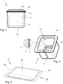
- the exemplary portion capsule 1 has a base element 11 with a base element axis 15.
- the base element 11 shown has the shape of a cup, the base element axis 15 being a cup axis.
- the portion capsule 1 also has a capsule lid 21 which is fastened along a circumferential flange 14 of the base element (cup) 11, the base element 11 and the capsule lid 21 together forming an outer capsule wall and defining a capsule interior.
- the base element 11 shown forms a base area (capsule base) 16, which is slightly curved here, and a circumferential area Side wall 12.
- the flange 14 shown is implemented as a collar of the circumferential side wall 12.
- the base element 11 and capsule lid 21 are formed from a cellulose-based sheet, more precisely a paper sheet, the base element 11 being formed from a first cellulose-based sheet 2 and the capsule lid 21 from a second cellulose-based sheet Sheet, the cellulose-based capsule lid sheet 25, is formed.
- the capsule cover 21 is fastened to the base element 11 by ultrasonic welding or by gluing.
- thermal welding is also conceivable, for example.
- the thermal welding can take place, for example, using an embossing that supports the welding process.
- the embossing can in particular be arranged on a surface of the welding partners to be welded, that is to say the capsule cover 21 and / or the base element 11.
- At least the surface of the collar 14 facing the capsule lid 21 or at least one surface of a circumferential cover collar 22 facing the collar 14 has a material which becomes flowable under ultrasound and pressure.
- This material is arranged in such a way and / or the said surfaces are shaped in such a way that, at the latest during the ultrasonic welding, the material arranged on one piece (collar 14 or cover collar 22) at least partially with the facing surface of the other piece (cover collar 22 or Collar 14) comes into contact. If, for example, only the collar 14 of the base element 11 has the material, this comes into contact with the surface of the cover collar 22 facing the collar 14 of the base element 11 at the latest during the ultrasonic welding of the capsule lid 21 to the base element 11.
- the material can be arranged on the surface of the collar and / or on the surface of the circumferential cover collar 22.
- the material can, however, also be covered by at least one further layer which it penetrates during the ultrasonic welding process or which is penetrated by at least part of the facing surface of the counterpart during the ultrasonic welding process (collar 14 if cover collar 22 has the covered material, cover collar 22 if collar 14 has the covered material) is penetrated.
- This part can, for example, be a circumferential extension.
- the material can in particular be the liquid sealing layer (sealing layer 3 for short) described below.
- the barrier layer described below which in the embodiments shown is a gas transmission barrier layer, more precisely an oxygen barrier layer 4, can be a layer that covers the material in the above sense.
- FIG. 2 shows a detailed view of the base element 11.
- the base element 11 is cup-like with a square basic shape. This means that the base element 11 has essentially the shape of a cube, one of the six sides of the cube being missing and forming an opening 13. Via this opening 13, extraction material can be introduced into the interior of the base element 11 and thus into the interior of the capsule.
- Other basic shapes such as a round basic shape (basic element essentially has the shape of a cylinder open on one flat side) are conceivable.
- the circumferential edge 14 to which the capsule lid 21 can be attached is primarily the circumferential edge 14 to which the capsule lid 21 can be attached, rounded edges and possibly slightly curved sides that cause a deviation from the shape of a cube.
- this can lead to lead to a further deviation from the shape of a cube.
- the base area 16 is flanged onto the circumferential side wall 12 or if the base area is attached to the circumferential side wall 12 in a manner analogous to the capsule cover.
- the bottom area 16 is formed by a simple folding over of the cellulose-based sheet 2 compared to the flanging, possibly including a fastening area and optionally a sealing area (e.g. in the area of the corners), the additional deviation from the shape of a cube can be more likely be small.
- the circumferential side wall 12 of the base element 11 shown is implemented as a complete winding of the cellulose-based sheet 2 around the base element axis 15. That is to say, the cellulose-based sheet 2 is arranged around the base element axis 15 in such a way that a starting area and an end area of the cellulose-based sheet 2 overlap in a fixing area 9 of the winding.
- the starting area is permanently connected to the end area, for example in that the areas are glued to one another or are connected by means of ultrasonic welding.
- the permanent winding implemented in this way forms the circumferential side wall 12 of the base element 11.
- both the starting area and the end area have a surface which can be brought into contact with one another during fixing.
- at least one of these surfaces has a material which becomes flowable under ultrasound and pressure.
- This material is arranged in such a way and / or the said surfaces are shaped in such a way that, at the latest during the ultrasonic welding, the material arranged on one piece (starting area or end area) at least partially comes into contact with the facing surface of the other piece (end area or starting area). If, for example, only the end area has the material, this comes into contact with the surface of the starting area facing the end area at the latest during the fixation by means of ultrasonic welding.
- the material can be arranged on the surface of the starting area and / or on the surface of the end area.
- the material can also be covered by at least one further layer which it penetrates during the ultrasonic welding process or which during the ultrasonic welding process at least from a part of the facing surface of the counterpart (starting area if the end area has the covered material, end area if the starting area has the covered material) is penetrated.
- This part can be an extension, for example.
- the cellulose-based sheet 2, from which the circumferential side wall 12 is formed, has a sealing layer 3 and an oxygen barrier layer 4 in the embodiment shown.
- the sealing layer 3 is a PLA layer and the oxygen barrier layer 4 is an SiO x layer.
- the sealing layer 3 - apart from any adhesive layer that may be present - is arranged directly on the cellulose-based sheet 2, while the oxygen barrier layer 4 - apart from any adhesive layer that may be present - is arranged directly on the sealing layer 3.
- Sealing layer 3 and oxygen barrier layer 4 are arranged in such a way, or the cellulose-based sheet 2 carrying these layers is wound around the base element axis 11, that the sealing layer 3 and the oxygen barrier layer 4 are arranged on the cellulose-based sheet 2 towards the interior of the base element 11 are.
- Sealing layer 3 and oxygen barrier layer 4 are arranged in such a way that the entire interior space delimited by base element 11 is continuously lined by these two layers.
- the material that becomes flowable during the ultrasonic welding process is the material of the sealing layer 3.
- the oxygen barrier layer 4 is then a layer which is penetrated by the liquefied material of the sealing layer 3 during the ultrasonic welding process and / or which is penetrated by the material of the counterpart (the starting area).
- FIG 3 shows a detailed view of the capsule lid 21.
- the capsule lid 21 is formed from the cellulose-based capsule lid sheet 25 which, before the capsule lid 21 is attached to the base element 11, is formed by the cellulose-based sheet 2 from which the circumferential side wall 12 is formed is, is separate.
- the capsule lid 21 shown has the layer sequence of sealing layer 3 and oxygen barrier layer 4 shown in connection with the base element 11, these layers being arranged on the cellulose-based capsule lid sheet 25 in such a way that the one formed after the capsule lid 21 has been attached to the base element 11 , closed interior of the portion capsule 1 is lined continuously with these layers.
- the capsule cover 21 has the circumferential collar 22, which is matched to the collar 14 of the base element 11, so that the capsule cover 21 can close the base element 11 in a fluid-tight manner when it is appropriately fastened.
- the in Figure 3 The capsule lid 21 shown is not designed as a bare sheet which, apart from the thickness of the sheet, represents a two-dimensional object. Such two-dimensional capsule lids are known from the prior art in the form of foils or plates.
- the capsule lid 21 shown has a bulge 23 to the outside.
- This bulge 23 forms a flat area in the middle.
- the flat area is offset to the outside with respect to a plane which is defined by the circumferential cover collar 22.
- Curvature 23 and cover collar 22 are connected to one another via a transition area 24.
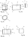
- Figure 4a shows an exemplary base element 11 which has the shape of a cup with a round basic shape.
- the base element 11 has essentially the shape of a cylinder, one flat side of the cylinder being open.
- the open flat side defines the opening 13 for introducing the extraction material into the interior of the base element 11 and thus into the interior of the capsule.
- the cup is oriented along the base element axis 15, which in the embodiment shown can be viewed as the cup axis.
- the base element 11 shown also has a flange (collar) 14 which surrounds the opening 13 circumferentially.
- the flange 14 can be implemented in one of the ways described above, except for its shape (circular instead of square basic shape).
- a capsule lid 21 can, apart from a configuration matched to the shape of the flange 14 and the opening 13, in one of the ways described above be realized.
- the capsule lid 21 can be or can be fastened to the base element 11 in one of the ways described above.
- the circumferential side wall 12 of the base element 11 is formed by a cellulose-based sheet 2 which forms a complete winding around the base element axis 15.
- the cellulose-based sheet 2, the winding and its fixing in a fixing area 9 can - apart from differences which are caused by the different shape of the base element 11 - be realized in one of the ways described above.
- the base area 16 of the base element 11 is formed by a cellulose-based base area sheet 17, which is separate from the cellulose-based sheet 2 before the base element 11 is formed.
- the base element 11 has a flange 8 on the side of the base element 11 opposite the opening 13.
- the flanging 8 is a flanging between the cellulose-based sheet 2, which forms the circumferential side wall 12, and the cellulose-based base area sheet 17, which forms the base area 16.
- the flanging 8 is realized in such a way that the base area 16 closes off the base element 11 permanently and without openings or "leaks".
- the base element shown is a changing cup with a bottom area flanged onto the circumferential side wall of the changing cup.
- FIG. 10 shows the cellulose-based sheet 2 before being wound around the base element axis 15.
- the cellulose-based sheet 2 has a side wall area 10 which, after winding, forms the circumferential side wall 12.
- the side wall area 10 can comprise the above-described starting area 31 and the above-described end area 32 for fixing the winding in the fixing area 9.
- At least the side wall area 10 has the sealing layer 3 and the barrier layer 4 in the embodiment shown.
- the end region 32 and / or the starting region 31 can have a layer or layer sequence that is different from the rest of the side wall region.
- the cellulose-based sheet 2 shown has a collar area (flange area) 5 which is arranged and shaped in such a way that it forms the circumferential collar 14 after winding.
- the cellulose-based sheet 2 shown has a flanged area 6 which is arranged and shaped in such a way that, together with a corresponding flanged area 18 of the cellulose-based base area sheet 17, it can form the flanging described above.
- FIG. 8 shows the cellulose-based bottom area sheet 17 before being flanged onto the cellulose-based sheet 2.
- the cellulose-based base area sheet 17 has an area 19 which, after being crimped, forms the actual base area 16 of the base element 11.
- the cellulose-based base area sheet 17 shown has the flanged area 18. This is arranged and shaped in such a way that it can form the previously described curling together with the curling area 6 of the cellulose-based sheet 2.
- At least the area 19, which after the crimping forms the actual bottom area 16 of the base element 11, has the sealing layer 3 described above and the oxygen barrier layer 4 described above.
- FIG. 4 shows a cellulose-based sheet 2 before being wound around the base element axis 15, which is an alternative to the one in FIG Figure 4b cellulose-based sheet 2 shown is.
- the cellulose-based sheet 2 shown is set up in such a way that, after winding, it has the circumferential side wall 12 and the circumferential collar 14 of a base element 11 with a square basic shape, as exemplified in FIG Figure 2 shown forms.
- cellulose-based sheet 2 shown has the in Figure 5a
- the cellulose-based sheet 2 shown has a side wall area 10 which is divided into four sub-areas by intended folds 7.
- the four partial areas are arranged in such a way that, after winding, they form the four flat sides of the circumferential side wall 12.
- the collar area 5 is divided into four parts, which are matched to the four sub-areas of the side wall area 10. These four parts are arranged and set up in such a way that, after the cellulose-based sheet 2 has been wound around the base element axis 15, they can run at an angle other than zero relative to the base element axis 15 and can form the circumferential collar 14.
- the circumferential collar 14 runs at approximately 90 ° to the base element axis 15, as in FIG Figures 1, 2 and 4a shown. That is to say, the circumferential collar 14 is arranged at least approximately in a plane whose normal runs parallel to the base element axis 15.
- Figure 5b shows, not to scale, a cellulose-based soil area sheet 17, which is based on the in Figure 5a Cellulose-based sheet 2 shown is matched and can be attached to this via a flange 8.
- the cellulose-based bottom area sheet 17 shown has a square area 19 which, after being crimped, forms the actual bottom area 16 of the base element 11.
- the flanged area 18 is divided into four sub-areas which are matched to the four sub-areas of the side wall area 10.
- the four partial areas of the flanged area 18 are arranged and set up in such a way that they can be folded away from the square area 19.
- the four partial areas of the flanged area 18 are arranged and shaped in such a way that, together with the flanged area 6 of the cellulose-based sheet 2, they can form the previously described flanging.
- Figure 6 shows schematically an exemplary method for producing a portion capsule 1 ready for consumption. Optional steps are also shown in the diagram.
- the exemplary method shown according to Figure 6 leads, in particular, to a portion capsule 1 that is ready to be consumed, which has a base area 16 which is flanged onto the circumferential side wall 12 and which is attached to one by means of ultrasonic welding encircling collar 14 of the encircling side wall 12 attached capsule lid 21.
- said cellulose-based sheets can be cut to size, provided with folding areas (if necessary), preformed (if necessary, for example capsule lids) and / or with an additionally machined starting area 31 and / or end region 32 (if necessary).
- folding areas if necessary
- preformed if necessary, for example capsule lids
- an additionally machined starting area 31 and / or end region 32 if necessary.
- one or more fastening areas and / or one or more sealing areas can be prepared.
- the base element 11 is formed.
- the method has a step in which the cellulose-based sheet 2 is deformed in this way that it forms a complete winding around an axis. This axis is henceforth the base element axis 15.
- the second phase of the method has a crimping step before, during or after the winding step.
- the cellulose-based base area sheet 17 is crimped onto the cellulose-based sheet 2, so that after the step of winding the base area 16 closes the circumferential wall 12 towards one end.
- the second phase of the method also usually includes a step in which the winding is locked so that it is permanent. This step is usually in addition to the flanging step.
- the base element 11 available after the second phase is filled with extraction material, for example coffee.
- the capsule lid 21 is attached to the filled base element 11 in order to close it and to produce the portion capsule 1 that is ready to be consumed.
- the fourth phase has a step in which the capsule lid 21, possibly as in connection with Figure 3 may be preformed as described, is positioned on the base element 11 in such a way that it closes the opening 13 and that the circumferential collar 14 of the base element 11 is circumferentially in contact with the cover collar 22.
- the fourth phase has a step in which the collars of the base element 11 and the capsule lid 21 which are in contact between an anvil and a sonotrode can be subjected to pressure and ultrasound, so that a weld around the former opening 13 is produced between the collar 14 of the base element 11 and the cover collar 22.
- the method can have further phases and steps. For example, a cleaning step, the application of labels and / or coding, coloring, etc.
Priority Applications (10)
| Application Number | Priority Date | Filing Date | Title |
|---|---|---|---|
| EP20173768.1A EP3907158A1 (fr) | 2020-05-08 | 2020-05-08 | Capsule et son procédé de fabrication |
| BR112022022673A BR112022022673A2 (pt) | 2020-05-08 | 2021-05-06 | Cápsula de porção e método para produzir uma cápsula de porção |
| EP21723740.3A EP4146565A1 (fr) | 2020-05-08 | 2021-05-06 | Capsule de portion et procédé de production d'une capsule de portion |
| KR1020227042777A KR20230037492A (ko) | 2020-05-08 | 2021-05-06 | 1회분 캡슐 및 1회분 캡슐을 제조하기 위한 방법 |
| CN202180048469.0A CN115916666A (zh) | 2020-05-08 | 2021-05-06 | 分装胶囊和用于制造分装胶囊的方法 |
| JP2022567610A JP2023525268A (ja) | 2020-05-08 | 2021-05-06 | ポーションカプセルおよびポーションカプセルの製造方法 |
| AU2021266404A AU2021266404A1 (en) | 2020-05-08 | 2021-05-06 | Portion capsule and method for producing a portion capsule |
| US17/923,385 US20230192391A1 (en) | 2020-05-08 | 2021-05-06 | Portion capsule and method for producing a portion capsule |
| PCT/EP2021/062070 WO2021224425A1 (fr) | 2020-05-08 | 2021-05-06 | Capsule de portion et procédé de production d'une capsule de portion |
| ZA2022/12347A ZA202212347B (en) | 2020-05-08 | 2022-11-11 | Portion capsule and method for producing a portion capsule |
Applications Claiming Priority (1)
| Application Number | Priority Date | Filing Date | Title |
|---|---|---|---|
| EP20173768.1A EP3907158A1 (fr) | 2020-05-08 | 2020-05-08 | Capsule et son procédé de fabrication |
Publications (1)
| Publication Number | Publication Date |
|---|---|
| EP3907158A1 true EP3907158A1 (fr) | 2021-11-10 |
Family
ID=70680321
Family Applications (2)
| Application Number | Title | Priority Date | Filing Date |
|---|---|---|---|
| EP20173768.1A Withdrawn EP3907158A1 (fr) | 2020-05-08 | 2020-05-08 | Capsule et son procédé de fabrication |
| EP21723740.3A Pending EP4146565A1 (fr) | 2020-05-08 | 2021-05-06 | Capsule de portion et procédé de production d'une capsule de portion |
Family Applications After (1)
| Application Number | Title | Priority Date | Filing Date |
|---|---|---|---|
| EP21723740.3A Pending EP4146565A1 (fr) | 2020-05-08 | 2021-05-06 | Capsule de portion et procédé de production d'une capsule de portion |
Country Status (9)
| Country | Link |
|---|---|
| US (1) | US20230192391A1 (fr) |
| EP (2) | EP3907158A1 (fr) |
| JP (1) | JP2023525268A (fr) |
| KR (1) | KR20230037492A (fr) |
| CN (1) | CN115916666A (fr) |
| AU (1) | AU2021266404A1 (fr) |
| BR (1) | BR112022022673A2 (fr) |
| WO (1) | WO2021224425A1 (fr) |
| ZA (1) | ZA202212347B (fr) |
Citations (11)
| Publication number | Priority date | Publication date | Assignee | Title |
|---|---|---|---|---|
| WO2011015973A1 (fr) | 2009-08-05 | 2011-02-10 | Ethical Coffee Company Sa | Membrane renforcee avec trame pour capsule utilisee dans la preparation d'une boisson |
| US20140335236A1 (en) | 2013-05-08 | 2014-11-13 | G Cup Technology Corp. | Biodegradable and compostable single-serve beverage ingredient package |
| WO2015059022A1 (fr) * | 2013-10-22 | 2015-04-30 | Nestec S.A. | Capsule de préparation d'une boisson telle que du café et analogue |
| WO2015096990A1 (fr) * | 2013-12-24 | 2015-07-02 | Luna Technology Systems Lts Gmbh | Capsule de portion pour la préparation d'un produit d'infusion et procédé de fabrication de celle-ci |
| WO2015121489A1 (fr) * | 2014-02-17 | 2015-08-20 | Ritter Gmbh | Récipient en matériau biodégradable à fonction barrière |
| EP3042860A1 (fr) * | 2015-01-08 | 2016-07-13 | Stas I.P. B.V. | Récipient contenant un produit à extraire, ainsi que la méthode pour la production du récipient |
| DE202016104950U1 (de) | 2015-09-10 | 2016-12-01 | Francesco SPIGNESI | Hermetisch verschließbare Portionspackung oder hermetisch verschließbarer Portionsbeutel mit einer biologisch abbaubaren Kaffeekapsel oder einem biologisch abbaubaren Kaffeepad |
| WO2017017704A1 (fr) | 2015-07-28 | 2017-02-02 | Rossomando Matteo | Contenant ou capsule biodégradable |
| WO2017072808A1 (fr) | 2015-10-30 | 2017-05-04 | Cossa Polimeri S.R.L. | Capsule pour préparer une infusion ou des boissons solubles |
| WO2017186743A1 (fr) | 2016-04-25 | 2017-11-02 | Spc Sunflower Plastic Compound Gmbh | Procédé de fabrication d'un produit en bioplastique |
| WO2019002420A1 (fr) | 2017-06-27 | 2019-01-03 | Caffe' Pascucci Torrefazione S.P.A. | Capsule biodégradable |
-
2020
- 2020-05-08 EP EP20173768.1A patent/EP3907158A1/fr not_active Withdrawn
-
2021
- 2021-05-06 JP JP2022567610A patent/JP2023525268A/ja active Pending
- 2021-05-06 BR BR112022022673A patent/BR112022022673A2/pt unknown
- 2021-05-06 CN CN202180048469.0A patent/CN115916666A/zh active Pending
- 2021-05-06 WO PCT/EP2021/062070 patent/WO2021224425A1/fr unknown
- 2021-05-06 EP EP21723740.3A patent/EP4146565A1/fr active Pending
- 2021-05-06 AU AU2021266404A patent/AU2021266404A1/en active Pending
- 2021-05-06 US US17/923,385 patent/US20230192391A1/en active Pending
- 2021-05-06 KR KR1020227042777A patent/KR20230037492A/ko active Search and Examination
-
2022
- 2022-11-11 ZA ZA2022/12347A patent/ZA202212347B/en unknown
Patent Citations (11)
| Publication number | Priority date | Publication date | Assignee | Title |
|---|---|---|---|---|
| WO2011015973A1 (fr) | 2009-08-05 | 2011-02-10 | Ethical Coffee Company Sa | Membrane renforcee avec trame pour capsule utilisee dans la preparation d'une boisson |
| US20140335236A1 (en) | 2013-05-08 | 2014-11-13 | G Cup Technology Corp. | Biodegradable and compostable single-serve beverage ingredient package |
| WO2015059022A1 (fr) * | 2013-10-22 | 2015-04-30 | Nestec S.A. | Capsule de préparation d'une boisson telle que du café et analogue |
| WO2015096990A1 (fr) * | 2013-12-24 | 2015-07-02 | Luna Technology Systems Lts Gmbh | Capsule de portion pour la préparation d'un produit d'infusion et procédé de fabrication de celle-ci |
| WO2015121489A1 (fr) * | 2014-02-17 | 2015-08-20 | Ritter Gmbh | Récipient en matériau biodégradable à fonction barrière |
| EP3042860A1 (fr) * | 2015-01-08 | 2016-07-13 | Stas I.P. B.V. | Récipient contenant un produit à extraire, ainsi que la méthode pour la production du récipient |
| WO2017017704A1 (fr) | 2015-07-28 | 2017-02-02 | Rossomando Matteo | Contenant ou capsule biodégradable |
| DE202016104950U1 (de) | 2015-09-10 | 2016-12-01 | Francesco SPIGNESI | Hermetisch verschließbare Portionspackung oder hermetisch verschließbarer Portionsbeutel mit einer biologisch abbaubaren Kaffeekapsel oder einem biologisch abbaubaren Kaffeepad |
| WO2017072808A1 (fr) | 2015-10-30 | 2017-05-04 | Cossa Polimeri S.R.L. | Capsule pour préparer une infusion ou des boissons solubles |
| WO2017186743A1 (fr) | 2016-04-25 | 2017-11-02 | Spc Sunflower Plastic Compound Gmbh | Procédé de fabrication d'un produit en bioplastique |
| WO2019002420A1 (fr) | 2017-06-27 | 2019-01-03 | Caffe' Pascucci Torrefazione S.P.A. | Capsule biodégradable |
Also Published As
| Publication number | Publication date |
|---|---|
| CN115916666A (zh) | 2023-04-04 |
| ZA202212347B (en) | 2024-04-24 |
| WO2021224425A1 (fr) | 2021-11-11 |
| US20230192391A1 (en) | 2023-06-22 |
| JP2023525268A (ja) | 2023-06-15 |
| BR112022022673A2 (pt) | 2022-12-13 |
| KR20230037492A (ko) | 2023-03-16 |
| AU2021266404A1 (en) | 2022-12-22 |
| EP4146565A1 (fr) | 2023-03-15 |
Similar Documents
| Publication | Publication Date | Title |
|---|---|---|
| EP2986514B1 (fr) | Capsule portion pour la préparation d'un produit ébouillanté | |
| EP2636607B1 (fr) | Récipient d'emballage combiné | |
| EP1905698B1 (fr) | Récipient doté d'un couvercle à ouverture facile, couvercle à ouverture facile ainsi qu'anneau de couvercle à ouverture facile | |
| EP2889224B1 (fr) | Capsule portion pour la préparation d'un produit ébouillanté et son procédé de fabrication | |
| WO2015121489A1 (fr) | Récipient en matériau biodégradable à fonction barrière | |
| EP2958812B1 (fr) | Récipient d'emballage combiné | |
| EP3322651B1 (fr) | Élément filtrant comprenant un évidement | |
| EP3360676B1 (fr) | Dispositif et procédé de fabrication de récipients en matériau de papier ou en matériau similaire au papier et récipient | |
| DE2936138A1 (de) | Doppelwandiger behaelter sowie verfahren und vorrichtung zu dessen herstellung | |
| DE10111232A1 (de) | Gasdichte Lebensmittelverpackung sowie Verfahren zu deren Herstellung | |
| EP2804706B1 (fr) | Procédé de fabrication d'une boîte métallique à opercule déchirable et boîte à opercule déchirable | |
| WO1996031406A1 (fr) | Boite munie d'une membrane de fermeture en feuille, ainsi que procede, dispositif et feuille pour la fabrication de cette boite | |
| EP3907158A1 (fr) | Capsule et son procédé de fabrication | |
| DE102019101545A1 (de) | Getränkeportionskapsel aus faserbasiertem Werkstoff sowie Verfahren zu deren Herstellung | |
| EP3724082B1 (fr) | Emballage et procédé pour sa fabrication | |
| EP2838807B1 (fr) | Récipient d'emballage combiné | |
| EP3907145A1 (fr) | Procédé de fabrication d'une capsule à portion et capsule à portion | |
| AT506749A1 (de) | Verfahren zur herstellung eines kombi-verpackungsbehälters | |
| EP4053038A1 (fr) | Capsule à portion biodégradable | |
| AT507739B1 (de) | Verfahren zur herstellung eines kombi - verpackungsbehälters | |
| DE2319129C3 (de) | Becher- oder schalenartiger Faltbehälter | |
| DE19823084A1 (de) | Verfahren zum Verschließen einer Verbunddose, Verbunddose und Boden für eine Verbunddose |
Legal Events
| Date | Code | Title | Description |
|---|---|---|---|
| PUAI | Public reference made under article 153(3) epc to a published international application that has entered the european phase |
Free format text: ORIGINAL CODE: 0009012 |
|
| STAA | Information on the status of an ep patent application or granted ep patent |
Free format text: STATUS: THE APPLICATION HAS BEEN PUBLISHED |
|
| AK | Designated contracting states |
Kind code of ref document: A1 Designated state(s): AL AT BE BG CH CY CZ DE DK EE ES FI FR GB GR HR HU IE IS IT LI LT LU LV MC MK MT NL NO PL PT RO RS SE SI SK SM TR |
|
| B565 | Issuance of search results under rule 164(2) epc |
Effective date: 20201125 |
|
| STAA | Information on the status of an ep patent application or granted ep patent |
Free format text: STATUS: THE APPLICATION IS DEEMED TO BE WITHDRAWN |
|
| 18D | Application deemed to be withdrawn |
Effective date: 20220511 |