EP3906769A1 - Antriebssystem für eine selbstfahrende erntemaschine - Google Patents
Antriebssystem für eine selbstfahrende erntemaschine Download PDFInfo
- Publication number
- EP3906769A1 EP3906769A1 EP21156516.3A EP21156516A EP3906769A1 EP 3906769 A1 EP3906769 A1 EP 3906769A1 EP 21156516 A EP21156516 A EP 21156516A EP 3906769 A1 EP3906769 A1 EP 3906769A1
- Authority
- EP
- European Patent Office
- Prior art keywords
- drive
- gear
- drive system
- shaft
- clutch
- Prior art date
- Legal status (The legal status is an assumption and is not a legal conclusion. Google has not performed a legal analysis and makes no representation as to the accuracy of the status listed.)
- Granted
Links
Images


Classifications
-
- A—HUMAN NECESSITIES
- A01—AGRICULTURE; FORESTRY; ANIMAL HUSBANDRY; HUNTING; TRAPPING; FISHING
- A01D—HARVESTING; MOWING
- A01D69/00—Driving mechanisms or parts thereof for harvesters or mowers
- A01D69/005—Non electric hybrid systems, e.g. comprising mechanical and/or hydraulic and/or pneumatic drives
-
- A—HUMAN NECESSITIES
- A01—AGRICULTURE; FORESTRY; ANIMAL HUSBANDRY; HUNTING; TRAPPING; FISHING
- A01D—HARVESTING; MOWING
- A01D43/00—Mowers combined with apparatus performing additional operations while mowing
- A01D43/08—Mowers combined with apparatus performing additional operations while mowing with means for cutting up the mown crop, e.g. forage harvesters
Definitions
- the present invention relates to a drive system for a self-propelled harvesting machine according to the preamble of claim 1. Furthermore, the invention relates to a self-propelled harvesting machine according to claim 15.
- the drive system comprises a drive motor, a transfer case driven by the drive motor with a driven pulley arranged on a drive shaft of the transfer case, which by means of a main drive belt drives at least one main pulley of a rotating knife drum, which is arranged at the end on a knife drum shaft, and at least one hydraulic pump driven by the drive motor for driving a Attachment and a retraction device.
- a second driven belt pulley is assigned to the transfer case, which drives the at least one hydraulic pump by means of the second belt.
- the second driven pulley for driving the hydraulic pump is arranged parallel to the first driven pulley of the transfer case.
- the main drive belt and the second belt run parallel to one another on a common side of the drive system.
- cardan shafts are arranged in parallel next to the main drive belt on the same side of the drive system to drive the attachment and the retraction device.
- the invention is therefore based on the object of developing a drive system of the type mentioned at the beginning in such a way that the drive system is constructed in a more compact manner and is set up to drive a wide variety of attachments in different operating modes including a reversing function.
- a drive system for a self-propelled harvesting machine comprising a drive motor, a transfer case driven by the drive motor with a first driven pulley arranged on a drive shaft of the transfer case, which by means of a main drive belt at least one main pulley arranged at the end on a cutterhead shaft of a rotating Drives knife drum, and comprises at least one hydraulic pump driven by the drive motor for hydraulically driving an attachment and / or a retraction device.
- a gear coupling unit is assigned to the end of the cutterhead shaft on the side opposite the main pulley, the gearbox coupling unit being set up to drive the attachment continuously or with a discrete gear ratio, the gearbox coupling unit having a transverse shaft running axially parallel to the cutterhead shaft drives, and the transverse shaft is drivingly connected to a coupling device located on the side of the main pulley for driving the attachment.
- the front attachment In a first shift position of the transmission / clutch unit, the front attachment can be driven purely hydraulically and continuously. In a second shift position of the gear-coupling unit, the drive of the attachment can be totalized with discrete transmission, i.e. hydraulically and additionally mechanically via the cutterhead shaft.
- the transmission / clutch unit can be driven by at least one hydraulic motor, which can be driven by the at least one hydraulic pump.
- the at least one hydraulic pump is connected to the main drive train of the drive system, which is formed by the drive motor, transfer case and the main drive belt.
- the at least one hydraulic pump is thus permanently connected to the main drive.
- the main drive train and the working elements driven by it can be braked.
- the hydraulic drive of the transmission / clutch unit by the at least one hydraulic motor enables the attachment to be driven continuously at a variable speed.
- the transmission / clutch unit can have a transmission arrangement and a drive belt pulley with a clutch integrated into the drive belt pulley.
- the gear arrangement With the gear arrangement, the speed of the at least one hydraulic motor can be stepped up or adjusted in such a way that the hydraulic motor works in an efficient operating range.
- the drive belt pulley can preferably be designed as a V-belt pulley.
- the gear arrangement can preferably be designed as a spur gear and / or spur gear bevel gear and the clutch as a friction clutch or as a form-fitting clutch.
- the clutch of the transmission clutch unit which is designed as a friction clutch, is preferably a dry-running single-disk clutch disk.
- the coupling can have a first coupling part, which is frictionally connected to the cutterhead shaft, and a second coupling part which is relatively movable with respect to the cutterhead shaft and which can be brought into frictional engagement with the drive belt pulley.
- the clutch which is preferably designed as a friction clutch or alternatively as a form-fitting clutch, is engaged at the power-cumulative operating point in which a lot of drive power is required for the attachment at a constant speed. It is advantageous that the shifting process of the clutch, which is designed as a friction clutch, is characterized by low wear and lower noise emissions compared to the prior art.
- the gear arrangement can be rotatably mounted on the cutterhead shaft.
- the rotatable mounting of the gear arrangement on the cutterhead shaft avoids the occurrence of an angle or length change when the attachment is pivoted, which would otherwise have to be accommodated in hose lines or a cardan shaft.
- the at least one hydraulic motor can be connected to the transmission arrangement by a double joint.
- the double joint connects the at least one hydraulic motor to the input of the transmission arrangement of the transmission coupling unit.
- the output of the gear assembly drives the drive pulley.
- the maintenance effort can be reduced by a double joint, in particular one that is maintenance-free.
- the hydraulic motor can, however, also be flanged directly to the gear arrangement.
- an output belt pulley can be arranged on the end of the transverse shaft, which is drivingly connected to the drive belt pulley of the transmission / clutch unit by a belt.
- the belt can be pretensioned by a tensioning device with variable tension.
- the tensioning device can comprise a tensioning roller that can be acted upon by a force by means of an actuator, in particular a hydraulic cylinder.
- the tensioning roller can also be acted upon purely mechanically by an actuator designed as a spring or a pneumatically actuated cylinder.
- the transverse shaft and the coupling device can be connected to one another by an input gear located on the side of the main pulley.
- the input gear can preferably have a bevel gear stage.
- the transmission-clutch unit can be operated in a speed-variable mode in which the clutch is opened, so that the attachment is driven by the at least one hydraulic motor. This enables a variable speed drive of the attachment.
- the gear-clutch unit can be operated in a power-accumulated mode in which the clutch is closed, so that the attachment is driven mechanically by means of the cutterhead shaft and the at least one hydraulic motor.
- the power output by the hydraulic motor can be minimized in order to reduce the power loss. It is also conceivable, however, to decouple the hydraulic motor from the gear-coupling unit for a purely mechanical drive of the attachment at a constant speed with the clutch of the gear-clutch unit engaged.
- the transmission clutch unit can be operated in a reversing mode in which the clutch is opened and the direction of rotation of the at least one hydraulic motor is inverted. In this way, problems in the crop flow within the intake device and / or the front attachment can be eliminated by driving them in a reversing manner.
- the hydraulic cylinder of the tensioning device can be subjected to a first pressure in the variable-speed mode and in the power-accumulated mode, while the hydraulic cylinder in the reversing mode or during a braking process in which the slack side and the load side change on the drive belt is subjected to a second pressure that is greater than the first print is.
- a first pressure in the variable-speed mode and in the power-accumulated mode
- the hydraulic cylinder in the reversing mode or during a braking process in which the slack side and the load side change on the drive belt is subjected to a second pressure that is greater than the first print is.
- a hydraulic motor and an adjoining gear and cardan shafts form a separate drive train, which is arranged above the main drive belt and parallel to it in a vertical plane.
- the hydraulic motor, the gearbox and the cardan shafts are arranged essentially within the belt width of the main drive belt and run above the main belt. In relation to the total width of the harvesting machine or the forage harvester, this frees up installation space, which is used to widen the working width of the working elements.
- the object set out at the beginning is achieved by a self-propelled harvesting machine, in particular a forage harvester, with a drive system according to one of Claims 1 to 14.
- the self-propelled harvesting machine can have all of the features described in connection with the drive system according to the invention, individually or in combination.
- FIG. 1 a schematic view of a self-propelled harvesting machine 1 designed as a forage harvester 2 is shown.
- the schematic illustration shows, viewed in the direction of travel FR, a view of the harvesting machine 1 designated as the left machine side ML.
- the opposite side is correspondingly designated as the right machine side MR.
- the forage harvester 2 harvests or picks up plants from the field by means of an attachment 4, in order to then collect the harvested crop 3 in the form of a crop flow (in Fig. 1 indicated as a line provided with arrows) through working elements, which are designed as processing and conveying elements of the forage harvester 2, and thrown by means of a loading device into a - not shown - loading container.
- the processing and conveying elements of the forage harvester 2 include, among other things, a feed device 5, a chopping device 6, an optional conditioning device 7 and an ejection accelerator 8.
- the draw-in device 5 consists of several driven roller pairs 5a, 5b arranged one behind the other in a draw-in housing 5c.
- the attachment 4 can be coupled to the pull-in device 5.
- the chopping device 6 comprises a rotating knife drum 6a equipped with knives, by means of which the harvested crop 3 is shredded in cooperation with a shearbar.
- the cutterhead 6a is arranged on a driven cutterhead shaft 6b.
- the optional conditioning device 7 is arranged downstream of the chopping device 6 in a conveying shaft in the crop flow conveying direction and can be removed from the crop flow if required.
- the conditioning device 7 in the conveying shaft is followed by the ejection accelerator 8 in the direction of crop flow, which accelerates the crop 3 by means of rotating throw paddles for safe ejection through the transfer device 10 designed as an ejection chute.
- the ejection accelerator 8 comprises conveyor elements 8a which are arranged non-rotatably on a shaft 8b.
- a drive motor 9 designed as an internal combustion engine is arranged as the main drive unit.
- attachment 4 that can be coupled to the intake device 5
- different attachment types are used, which are selected depending on the type of crop to be processed.
- a so-called pick-up on the forage harvester 2 is used to pick up crop material deposited in swaths.
- a disc mower is used.
- a row-independent maize header or a row-dependent maize picker is coupled to the intake device 5 of the forage harvester 2.
- attachments 4 which are not listed exhaustively, differ with regard to their drive due to different operating specifications.
- the maize header or the pick-up require a variable drive speed, while the disc mower works with a constant drive speed.
- the power consumption of the disc mower is higher than that of the pick-up or the maize header.
- a schematic perspective view of a drive system 50 according to the invention of the harvesting machine 1 designed as a forage harvester 2 is shown.
- the illustration only shows the components of the drive system 50, which are used to transmit power to the various working organs, the attachment 4, the intake device 5, the chopping device 6, the optional conditioning device 7 and the ejection accelerator 8.
- the drive components of the intake device 5, the chopping device 6 and the ejection accelerator 8, which extend essentially in the longitudinal direction, are arranged on the left-hand side of the machine ML.
- the drive components of the attachment 4, which extend essentially in the longitudinal direction, and of the optional conditioning device 7 are arranged opposite them on the right-hand side of the machine ML.
- intake device 5 chopping device 6, conditioning device 7 and the ejection accelerator 8 spaced the drive components apart in the transverse direction of the forage harvester 2.
- the above-described arrangement of the components of the drive system 50 can also be provided in a mirror-inverted manner.
- the drive motor 9 drives a transfer case 11 arranged on the left side of the machine ML via a motor shaft (not shown).
- the transfer case 11 comprises an output belt pulley 12 which is arranged on a first drive shaft and which is switchably connected to the motor shaft of the drive motor 9 by a hydraulically actuated clutch 13. Furthermore, on a second drive shaft of the transfer case 11, at least one hydraulic pump 14 is connected directly to the transfer case 11.
- At least one main pulley 16 arranged at the end on the cutterhead shaft 6b is driven by the driven pulley 12 by means of a main drive belt 15.
- the underside and 15b of the main drive belt 15 are denoted by 15a.
- the underside 15a forms the load strand or pulling strand and the top 15b the slack strand or pulled strand.
- the main drive belt 15 drives the ejection accelerator 8 via a pulley 17 arranged on the shaft 8b.
- the upper side 15b of the main drive belt 15 is subjected to an adjustable tension by a tensioning device 18, which comprises a tensioning roller 19 pivotable about an axis 20 and a hydraulic cylinder 21.
- a hydraulic motor 22 is arranged on the left machine side ML.
- the hydraulic motor 22 is arranged above the main drive belt 15 and lying essentially parallel to it in a vertical plane.
- the hydraulic motor 22 is driven by the at least one hydraulic pump 14.
- a drive shaft of the hydraulic motor 22 drives a gear 23 which is connected via cardan shafts 24 to the draw-in device 5 to be driven.
- a gear 24a can be arranged between the cardan shafts 24.
- the hydraulic motor 22 as well as the adjoining gear 23 and the articulated shafts 24 form a separate drive train 51 for driving the pull-in device 5.
- the drive train 51 is arranged above the main drive belt and lying essentially parallel to it in a vertical plane.
- the drive train 51 can be arranged differently from an exactly parallel arrangement lying only in a vertical plane.
- the drive train 51 can thus also contain an additional angle transverse to the direction of travel FR.
- the cardan shafts 24 and the gear mechanism 24a arranged between them are thus also arranged essentially parallel to the main drive belt 15 and lying essentially in a vertical plane to this.
- the arrangement of the separate drive train 51 made up of hydraulic motor 22, gear 23 and at least the cardan shafts 24 takes place essentially within the belt width of the main drive belt 15 and runs above the main belt 15. which benefits the enlargement of the working width of the working organs.
- a belt drive 25 is provided which - not shown - is drivingly connected to the ejection accelerator 8.
- a gear coupling unit 26 is arranged on the right machine side MR.
- the transmission clutch unit 26 is driven by at least one hydraulic motor 27, which can be driven by a further hydraulic pump 14a connected directly to the transfer case 11.
- the gear coupling unit 26 can also be driven by the cutterhead shaft 6b.
- the gear coupling unit 26 is preferably mounted on the knife drum motor shaft 6b.
- the gear coupling unit 26 drives a transverse shaft 28 running axially parallel to the cutterhead shaft 6b.
- the transverse shaft 28 is drivingly connected to a coupling device 29 for driving the attachment 4, which is located on the side of the main belt pulley 16, ie on the left machine side ML.
- the transverse shaft 28 runs through the intake housing 5c of the intake device 5.
- the representation in Fig. 3 shows a simplified drive scheme of the drive system 50.
- the simplified drive scheme shows only the components necessary for driving the attachment 4.
- the gear-coupling unit 26 is set up to drive the front attachment 4 continuously hydraulically or with a discrete gear ratio in a cumulative manner.
- the hydraulic motor 27 driven by the hydraulic pump 14a can be connected to an input shaft 31 of the transmission / clutch unit 26 by a double joint 30.
- the transmission / clutch unit 26 has a transmission arrangement 32 and a drive belt pulley 33 with a clutch 34, in particular integrated into the drive belt pulley 33.
- the gear arrangement 32 is designed as a spur gear bevel gear. With the gear arrangement 32, the speed of the hydraulic motor 27 is stepped up or adjusted in such a way that the hydraulic motor 27 works in an efficient operating range.
- the hydraulic motor 27 drives the transmission arrangement 32 by means of the input shaft 31.
- the drive belt pulley 33 with the clutch 34 integrated therein is arranged on an output shaft 35 of the gear arrangement 32.
- the gear arrangement 32 is mounted on the cutterhead shaft 6b.
- the output shaft 35 is mounted on the knife drum shaft 6b so as to be rotatable relative to the latter. Since the gear arrangement 32 is rotatably mounted on the cutterhead shaft 6b, there is no change in angle or length when the attachment 4 is pivoted, which would normally have to be absorbed by hose lines or a cardan shaft.
- the clutch 34 designed as a friction clutch has a first clutch part 34a, which is positively connected to the cutterhead shaft 6b, and a second coupling part 34b which is relatively movable with respect to the cutterhead shaft 6b and which is positively connected to the drive belt pulley 33.
- the two coupling parts 34a, 34b can be actuated by a hydraulic Apply pressure to frictionally connect them to one another.
- the clutch 34 designed as a friction clutch has the advantage that it works with little noise and with little wear.
- the clutch 34 designed as a friction clutch can be a dry-running single-disk clutch disk. Instead of the hydraulically operated clutch 34, the use of a pneumatically or electromechanically operated clutch is also conceivable.
- a driven belt pulley 36 is arranged, which is connected by a belt 37 to the drive belt pulley 33 of the transmission coupling unit 26.
- the belt 37 is pre-tensioned by a tensioner 40 with variable tension.
- the tensioning device 40 comprises a tensioning roller 41 which can be acted upon by a force by means of a hydraulic cylinder 42 and which is pressed against the belt 37.
- the coupling device 29 is arranged on the opposite shaft end of the transverse shaft 28 on the left machine side ML.
- the coupling device 29 comprises an input gear 38 with a bevel gear stage as well as a quick coupler 39 to which the attachment 4 is connected for driving the same.
- the hydraulically actuated clutch 34 is in a switching position in which the two clutch parts 34a, 34b are disengaged, i.e. the clutch 34 is open.
- the transmission / clutch unit 26 can be operated in a speed-variable mode, so that the attachment 4 is driven by the at least one hydraulic motor 27.
- the attachment 4 can be driven in a speed-variable manner.
- the clutch 34 In order to operate the transmission-clutch unit 26 in a power-accumulated mode, the clutch 34 is closed. As a result, the two coupling parts 34a, 34b are frictionally engaged with one another, so that the attachment 4 is driven mechanically by means of the cutterhead shaft 6b driven by the main drive belt 15 and by the at least one hydraulic motor 27. It can the power output by the hydraulic motor 27 can be minimized in order to reduce the power loss.
- the totalized operation can be used for all types of attachments. In particular, the power-cumulated operation is used for front attachments 4 designed as maize pickers or direct cutting units, since the speed is constant in this operating mode.
- the transmission clutch unit 26 can be operated in a reversing mode in which the clutch 34 is opened and the direction of rotation of the at least one hydraulic motor 27 is inverted.
- problems in the crop flow within the intake device 5 and / or the attachment 4 can be eliminated by driving them in a reversing manner.
- the direction of rotation of the hydraulic motor 22, which drives the pull-in device 5 is also inverted.
- the directions of rotation of the two hydraulic motors 22 and 27 are inverted independently of one another.
- the pull-in device 5 and the attachment 4 can also be reversed individually, independently of one another.
- the front attachment 4 can be braked and accelerated hydraulically, with the clutch 34 being opened.
- At least one of the hydraulic pumps 14, 14a is connected to the main drive train formed by the drive motor 9, the transfer case 11 and the main drive belt 15 and can be used for braking.
- By opening the clutch 13, the drive train between the drive motor 9 and the transfer case 11 is interrupted.
- the power of the still rotating working elements transferred from the main drive belt 15 to the transfer case 11 is absorbed by at least one of the hydraulic pumps 14, 14a, so that the working elements come to a standstill within seconds.
- the hydraulic cylinder 42 of the tensioning device 40 is subjected to a first pressure in the variable-speed mode and in the power-accumulated mode of the transmission-clutch unit 26, while the hydraulic cylinder 42 is subjected to a second pressure in the reversing mode or during a braking process in which the belt 37 alternates between the slack side and the load side is applied, which is greater than the first pressure.
- torque can also be transmitted reliably in the case of a reverse thrust.
- the hydraulic pressure with which the hydraulic cylinders 21 and 42 of the clamping devices 18 and 40 are supplied is provided by a pressure source of the self-propelled harvesting machine 1 or the forage harvester 2.
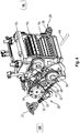
- Fig. 4 shows a schematic perspective view of the pull-in device 5 with the clutch-gear unit 26 arranged thereon on the right machine side MR, the tensioning device 40 as well as the driven pulley 36 and the belt 37.
- the coupling device 29 with the quick coupler 39 at the end can be seen .
Landscapes
- Engineering & Computer Science (AREA)
- Mechanical Engineering (AREA)
- Life Sciences & Earth Sciences (AREA)
- Environmental Sciences (AREA)
- Harvester Elements (AREA)
Abstract
Description
- Die vorliegende Erfindung betrifft ein Antriebssystem für eine selbstfahrende Erntemaschine gemäß dem Oberbegriff des Anspruches 1. Weiterhin betrifft die Erfindung eine selbstfahrende Erntemaschine gemäß dem Anspruch 15.
- Aus der
DE 10 2014 108 026 A1 ist ein Antriebssystem für eine selbstfahrende Erntemaschine gemäß dem Oberbegriff des Anspruches 1 bekannt. Das Antriebssystem umfasst einen Antriebsmotor, ein von dem Antriebsmotor angetriebenes Verteilergetriebe mit einer an einer Antriebswelle des Verteilergetriebes angeordneten Abtriebsriemenscheibe, welche mittels eines Hauptantriebsriemens zumindest eine endseitig auf einer Messertrommelwelle angeordnete Hauptriemenscheibe einer rotierenden Messertrommel antreibt, und mindestens eine von dem Antriebsmotor angetriebene Hydraulikpumpe zum Antrieb eines Vorsatzgerätes und einer Einzugsvorrichtung. Dem Verteilergetriebe ist eine zweite Abtriebsriemenscheibe zugeordnet, die mittels des zweiten Riemens die mindestens eine Hydraulikpumpe antreibt. Die zweite Abtriebsriemenscheibe zum Antreiben der Hydraulikpumpe ist parallel zu der ersten Abtriebsriemenscheibe des Verteilergetriebes angeordnet ist. Der Hauptantriebsriemen und der zweite Riemen verlaufen parallel zueinander auf einer gemeinsamen Seiten des Antriebssystems. Weiterhin sind zum Antreiben von Vorsatzgerät und Einzugsvorrichtung Gelenkwellen parallel neben dem Hauptantriebsriemen auf der gleichen Seite des Antriebssystems angeordnet. Die gemäß derDE 10 2014 108 026 A1 bekannte Anordnung der leistungsübertragenden Baugruppen beschränkt die Arbeitsbreite der gutbearbeitenden Arbeitsorgane, d.h. insbesondere der Einzugsvorrichtung mit ihren Vorpresswalzen und Einzugswalzen sowie der nachgeordneten Messertrommel. Dies hat zur Folge, dass für die Elemente des Antriebssystems in der Breite der Erntemaschine weniger Bauraum zur Verfügung steht, da die Maschinenbreite aufgrund von Straßenverkehrsvorschriften nicht weiter erhöht werden kann. - Der Erfindung liegt somit die Aufgabe zu Grunde, ein Antriebssystem der eingangs genannten Art derart weiterzubilden, dass das Antriebssystem kompakter aufgebaut ist und dabei zum Antreiben verschiedenster Vorsatzgeräte in unterschiedlichen Betriebsmodi einschließlich einer Reversierfunktion eingerichtet ist.
- Diese Aufgabe wird durch ein Antriebssystem gemäß dem Oberbegriff des Anspruches 1 in Verbindung mit den kennzeichnenden Merkmalen gelöst. Vorteilhafte Weiterbildungen sind Gegenstand der von Anspruch 1 anhängigen Unteransprüche. Weiterhin wird die Aufgabe durch eine selbstfahrende Erntemaschine gemäß den Merkmalen des Anspruches 15 gelöst.
- Gemäß dem Anspruch 1 wird ein Antriebssystem für eine selbstfahrende Erntemaschine vorgeschlagen, wobei das Antriebssystem einen Antriebsmotor, ein von dem Antriebsmotor angetriebenes Verteilergetriebe mit einer an einer Antriebswelle des Verteilergetriebes angeordneten ersten Abtriebsriemenscheibe, welche mittels eines Hauptantriebsriemens zumindest eine endseitig auf einer Messertrommelwelle angeordnete Hauptriemenscheibe einer rotierenden Messertrommel antreibt, und mindestens eine von dem Antriebsmotor angetriebene Hydraulikpumpe zum hydraulischen Antreiben eines Vorsatzgerätes und/oder einer Einzugsvorrichtung umfasst. Erfindungsgemäß ist vorgesehen, dass der Messertrommelwelle auf der der Hauptriemenscheibe gegenüberliegenden Seite endseitig eine Getriebe-Kupplungseinheit zugeordnet ist, wobei die Getriebe-Kupplungseinheit dazu eingerichtet ist, das Vorsatzgerät stufenlos oder mit diskreter Übersetzung anzutreiben, wobei die Getriebe-Kupplungseinheit eine achsparallel zur Messertrommelwelle verlaufende Querwelle antreibt, und die Querwelle mit einer auf der Seite der Hauptriemenscheibe befindlichen Kuppeleinrichtung für den Antrieb des Vorsatzgerätes trieblich verbunden ist. Durch ein derart aufgelöstes Antriebssystem wird der erforderliche Bauraumbedarf reduziert, so dass die Arbeitsbreite der gutbearbeitenden Arbeitsorgane vergrößert werden kann. Der Antriebsmotor kann mit dem Verteilergetriebe und dem Hauptantriebsriemen einen Hauptantriebsstrang des Antriebssystems bilden. In einer ersten Schaltstellung der Getriebe-Kupplungseinheit kann der Antrieb des Vorsatzgerätes rein hydraulisch stufenlos erfolgen. In einer zweiten Schaltstellung der Getriebe-Kupplungseinheit kann der Antrieb des Vorsatzgerätes leistungssummiert mit diskreter Übersetzung erfolgen, d.h. hydraulisch und zusätzlich mechanisch über die Messertrommelwelle.
- Insbesondere kann die Getriebe-Kupplungseinheit durch zumindest einen Hydraulikmotor angetrieben sein, welcher durch die mindestens eine Hydraulikpumpe antreibbar ist.
- Die mindestens eine Hydraulikpumpe ist mit dem von Antriebsmotor, Verteilergetriebe und dem Hauptantriebsriemen gebildeten Hauptantriebsstrang des Antriebssystems verbunden. Die mindestens eine Hydraulikpumpe ist somit permanent mit dem Hauptantrieb verbunden. Dadurch kann ein Abbremsen des Hauptantriebsstranges und der von diesem angetriebenen Arbeitsorganen erreicht werden. Das hydraulische Antreiben der Getriebe-Kupplungseinheit durch den zumindest einen Hydraulikmotor ermöglicht einen stufenlosen Antrieb des Vorsatzgerätes mit veränderlicher Drehzahl.
- Dazu kann die Getriebe-Kupplungseinheit eine Getriebeanordnung sowie eine Antriebsriemenscheibe mit einer in die Antriebsriemenscheibe integrierten Kupplung aufweisen. Mit der Getriebeanordnung kann die Drehzahl des zumindest einen Hydraulikmotors so übersetzt bzw. eingestellt werden, dass der Hydraulikmotor in einem effizienten Betriebsbereich arbeitet. Die Antriebsriemenscheibe kann bevorzugt als Keilriemenscheibe ausgeführt sein.
- Bevorzugt kann die Getriebeanordnung als Stirnradgetriebe und/oder Stirnradwinkelgetriebe und die Kupplung als Reibkupplung oder als formschlüssige Kupplung ausgeführt sein. Bei der als Reibkupplung ausgeführten Kupplung der Getriebe-Kupplungseinheit handelt es sich vorzugsweise sich um eine trockenlaufende Einscheibenkupplungslamelle. Die Kupplung kann dabei einen ersten Kupplungsteil, welcher mit der Messertrommelwelle kraftschlüssig verbunden ist, und einen gegenüber der Messertrommelwelle relativbeweglichen zweiten Kupplungsteil aufweisen, welcher mit der Antriebsriemenscheibe kraftschlüssig in Eingriff bringbar ist. Die bevorzugt als Reibkupplung oder alternativ als formschlüssige Kupplung ausgeführte Kupplung wird dabei im leistungssummierten Betriebspunkt, in dem für das Vorsatzgerät viel Antriebsleistung bei konstanter Drehzahl benötigt wird, eingekuppelt. Vorteilhaft ist dabei, dass der Schaltvorgang der als Reibkupplung ausgeführten Kupplung sich gegenüber dem Stand der Technik durch einen geringen Verschleiß sowie geringere Geräuschemission auszeichnet.
- Insbesondere kann die Getriebeanordnung auf der Messertrommelwelle drehbar gelagert sein. Durch das drehbare Lagern der Getriebeanordnung auf der Messertrommelwelle wird das Auftreten einer Winkel- oder Längenänderung beim Verschwenken des Vorsatzgerätes vermieden, welche ansonsten in Schlauchleitungen oder einer Gelenkwelle aufgenommen werden müssten.
- Vorteilhaft ist, dass der zumindest eine Hydraulikmotor durch ein Doppelgelenk mit der Getriebeanordnung verbunden sein kann. Das Doppelgelenk verbindet den zumindest einen Hydraulikmotor mit dem Eingang der Getriebeanordnung der Getriebe-Kupplungseinheit. Der Ausgang der Getriebeanordnung treibt die Antriebsriemenscheibe an. Der Wartungsaufwand kann durch ein, insbesondere wartungsfrei ausgeführtes, Doppelgelenk verringert werden. Insbesondere kann durch die Verwendung des Doppelgelenks beim Einbau und Ausbau der Getriebeanordnung das Trennen von Hydraulikleitungen und das Trennen des Hydraulikmotors vermieden werden. Der Hydraulikmotor kann jedoch auch unmittelbar an die Getriebeanordnung angeflanscht sein.
- Weiterhin kann auf der Querwelle endseitig eine Abtriebsriemenscheibe angeordnet sein, welche durch einen Riemen mit der Antriebsriemenscheibe der Getriebe-Kupplungseinheit trieblich verbunden ist.
- Dabei kann der Riemen durch eine Spannvorrichtung mit veränderbarer Spannung vorgespannt sein.
- Insbesondere kann die Spannvorrichtung eine mittels eines Aktors, insbesondere eines Hydraulikzylinders, mit einer Kraft beaufschlagbare Spannrolle umfassen. Die Beaufschlagung der Spannrolle kann auch rein mechanisch durch eine als Feder ausgeführten Aktor oder einen pneumatisch betätigbaren Zylinder erfolgen.
- In bevorzugter Weiterbildung können die Querwelle und die Kuppeleinrichtung durch ein auf der Seite der Hauptriemenscheibe befindliches Eingangsgetriebe miteinander verbunden sein. Dadurch können das von der Querwelle übertragene Drehmoment bzw. die Drehzahl angepasst werden, bevor diese von der Kuppeleinrichtung auf das Vorsatzgerät übertragen werden. Das Eingangsgetriebe kann bevorzugt eine Kegelradstufe aufweisen.
- Die Getriebe-Kupplungseinheit ist in einem drehzahlvariablen Modus betreibbar, in welchem die Kupplung geöffnet ist, so dass der Antrieb des Vorsatzgerätes durch den zumindest einen Hydraulikmotor erfolgt. Hierdurch wird ein drehzahlvariabler Antrieb des Vorsatzgerätes ermöglicht.
- Des Weiteren ist die Getriebe-Kupplungseinheit in einem leistungssummierten Modus betreibbar, in welchem die Kupplung geschlossen ist, so dass der Antrieb des Vorsatzgerätes mechanisch mittels der Messertrommelwelle und durch den zumindest einen Hydraulikmotor erfolgt. Dabei kann die vom Hydraulikmotor abgegebene Leistung minimiert werden, um die Verlustleistung zu reduzieren. Denkbar ist es aber auch, für einen rein mechanischen Antrieb des Vorsatzgerätes mit konstanter Drehzahl bei geschlossener Kupplung der Getriebe-Kupplungseinheit den Hydraulikmotor von der Getriebe-Kupplungseinheit zu entkoppeln.
- Weiterhin ist die Getriebe-Kupplungseinheit in einem Reversiermodus betreibbar, in welchem die Kupplung geöffnet und die Drehrichtung des zumindest einen Hydraulikmotor invertiert ist. Auf diese Weise lassen sich Probleme im Gutfluss innerhalb der Einzugsvorrichtung und/oder des Vorsatzgerätes beheben, in dem diese reversierend angetrieben werden.
- Dabei kann der Hydraulikzylinder der Spannvorrichtung im drehzahlvariablen Modus und im leistungssummierten Modus mit einem ersten Druck beaufschlagt sein, während der Hydraulikzylinder im Reversiermodus oder während eines Bremsvorganges, in welchen am Antriebsriemen Leertrum und Lasttrum wechseln, mit einem zweiten Druck beaufschlagt ist, der größer als der erste Druck ist. Um im Reversiermodus oder während eines Bremsvorganges ein Drehmoment übertragen zu können, muss sichergestellt werden, dass die Spannrolle der Spannvorrichtung durch den die Getriebe-Kupplungseinheit mit der Abtriebsriemenscheibe der Querwelle verbindenden Riemen nicht nach oben gedrückt werden kann.
- Zum Antreiben der Einzugsvorrichtung bilden ein Hydraulikmotor sowie ein sich daran anschließendes Getriebe und Gelenkwellen einen separaten Antriebsstrang, der oberhalb des Hauptantriebsriemens und parallel zu diesem in einer vertikalen Ebene liegend angeordnet ist. Die Anordnung des Hydraulikmotors, des Getriebes sowie der Gelenkwellen erfolgt im Wesentlichen innerhalb der Riemenbreite des Hauptantriebsriemens und verläuft oberhalb des Hauptriemens. Dadurch wird bezogen auf die Gesamtbreite der Erntemaschine bzw. des Feldhäckslers Bauraum frei, welcher der Verbreiterung der Arbeitsbreite der Arbeitsorgane zukommt.
- Weiterhin wird die eingangs gestellte Aufgabe durch eine selbstfahrende Erntemaschine, insbesondere einen Feldhäcksler, mit einem Antriebssystem nach einem der Ansprüche 1 bis 14 gelöst.
- Die selbstfahrende Erntemaschine kann alle im Zusammenhang mit dem erfindungsgemäßen Antriebssystem beschriebenen Merkmale einzeln oder in Kombination aufweisen.
- Die vorliegende Erfindung wird nachstehend anhand eines in den Zeichnungen dargestellten Ausführungsbeispieles näher erläutert.
- Es zeigen:
- Fig. 1
- eine schematische Ansicht einer als Feldhäcksler ausgeführten selbstfahrenden Erntemaschine;
- Fig. 2
- eine schematisierte perspektivische Ansicht eines Antriebssystems für eine selbstfahrende Erntemaschine;
- Fig. 3
- ein vereinfachtes Antriebsschema des Antriebssystems; und
- Fig. 4
- schematisch eine perspektivische Ansicht einer Einzugsvorrichtung mit einer daran angeordneten Kupplungs-Getriebeeinheit.
- In
Fig. 1 ist eine schematische Ansicht einer als Feldhäcksler 2 ausgeführten selbstfahrenden Erntemaschine 1 dargestellt. Die schematische Darstellung zeigt in Fahrtrichtung FR gesehen eine als linke Maschinenseite ML bezeichnete Ansicht der Erntemaschine 1. Die gegenüberliegende Seite wird entsprechend als rechte Maschinenseite MR bezeichnet. - Der Feldhäcksler 2 erntet beziehungsweise nimmt mittels eines Vorsatzgerätes 4 Pflanzen vom Feld auf, um anschließend das aufgenommene Erntegut 3 in Form eines Erntegutstroms (in
Fig. 1 als mit Pfeilen versehene Linie angedeutet) durch Arbeitsorgane, die als Bearbeitungs- und Förderorgane des Feldhäckslers 2 ausgeführt sind, zuzuführen und mittels einer Überladeeinrichtung in einen - nicht dargestellten - Ladebehälter abzuwerfen. Die Bearbeitungs- und Förderorgane des Feldhäckslers 2 umfassen unter anderem eine Einzugsvorrichtung 5, eine Häckselvorrichtung 6, eine optionale Konditioniereinrichtung 7 sowie einen Auswurfbeschleuniger 8. - Die Einzugsvorrichtung 5 besteht aus mehreren, in einem Einzugsgehäuse 5c hintereinander angeordneten angetriebenen Walzenpaaren 5a, 5b. Das Vorsatzgerät 4 ist an die Einzugsvorrichtung 5 ankoppelbar. Die Häckselvorrichtung 6 umfasst eine rotierende, mit Messern ausgestatteten Messertrommel 6a mittels der das aufgenommene Erntegut 3 in Zusammenwirkung mit einer Gegenschneide zerkleinert wird. Die Messertrommel 6a ist auf einer angetriebenen Messertrommelwelle 6b angeordnet. Der Häckselvorrichtung 6 ist in einem Förderschacht in Gutstromförderrichtung nachgelagert die optionale Konditioniereinrichtung 7 angeordnet, die bei Bedarf aus dem Erntegutstrom entfernbar ist. Der Konditioniereinrichtung 7 im Förderschacht ist in Gutstromförderrichtung der Auswurfbeschleuniger 8 nachgelagert, welcher das Erntegut 3 mittels rotierender Wurfpaddel für den sicheren Auswurf durch die als Auswurfkrümmer ausgeführte Überladeeinrichtung 10 beschleunigt. Der Auswurfbeschleuniger 8 umfasst auf einer Welle 8b drehfest angeordnete Förderelemente 8a. Im rückwärtigen Bereich des Feldhäckslers 2 ist ein als Verbrennungsmotor ausgeführter Antriebsmotor 9 als Hauptantriebsaggregat angeordnet.
- Als an die Einzugsvorrichtung 5 ankoppelbare Vorsatzgerät 4 kommen unterschiedliche Vorsatzgerätetypen zum Einsatz, die in Abhängigkeit von der zu verarbeitenden Erntegutart ausgewählt werden. Beispielsweise wird zur Aufnahme von in Schwaden abgelegtem Erntegut eine so genannte Pick-up am Feldhäcksler 2 verwendet. Für das Ernten von Ganzpflanzen kommt hingegen ein Scheibenmähwerk zum Einsatz. Beim Ernten von Mais wird ein reihenunabhängig arbeitendes Maisgebiss oder ein reihenabhängig arbeitender Maispflücker an die Einzugsvorrichtung 5 des Feldhäckslers 2 angekoppelt.
- Die vorgenannten, nicht abschließend aufgezählten Vorsatzgeräte 4 unterscheiden sich hinsichtlich ihres Antriebes durch unterschiedliche Betriebsspezifikationen. So bedürfen beispielsweise das Maisgebiss oder die Pick-up einer variablen Antriebsdrehzahl, während das Scheibenmähwerk mit einer konstanten Antriebsdrehzahl arbeitet. Des Weiteren ist die Leistungsaufnahme des Scheibenmähwerkes höher als die der Pick-up oder des Maisgebisses.
- In
Fig. 2 ist eine schematisierte perspektivische Ansicht eines erfindungsgemäßen Antriebssystems 50 des als Feldhäcksler 2 ausgeführten Erntemaschine 1 dargestellt. Die Darstellung zeigt lediglich die Komponenten des Antriebssystems 50, welche der Kraftübertragung zu den verschiedenen Arbeitsorganen, dem Vorsatzgerät 4, der Einzugsvorrichtung 5, der Häckselvorrichtung 6, der optionalen Konditioniereinrichtung 7 sowie dem Auswurfbeschleuniger 8, dienen. Die sich im Wesentlichen in Längsrichtung erstreckenden Antriebskomponenten der Einzugsvorrichtung 5, der Häckselvorrichtung 6 sowie des Auswurfbeschleunigers 8 sind auf der linken Maschinenseite ML angeordnet. Die sich im Wesentlichen in Längsrichtung erstreckenden Antriebskomponenten des Vorsatzgerätes 4 sowie der optionalen Konditioniereinrichtung 7 sind diesen gegenüberliegend auf der rechten Maschinenseite ML angeordnet. Die unter anderem inFig. 2 nicht dargestellte Einzugsvorrichtung 5, Häckselvorrichtung 6, Konditioniereinrichtung 7 sowie der Auswurfbeschleuniger 8 beabstanden die Antriebskomponenten in Querrichtung des Feldhäckslers 2 zueinander. Die vorstehend beschriebene Anordnung der Komponenten des Antriebssystems 50 kann entsprechen auch spiegelbildlich vorgesehen sein. - Der Antriebsmotor 9 treibt über eine - nicht dargestellte - Motorwelle ein auf der linken Maschinenseite ML angeordnetes Verteilergetriebe 11 an. Das Verteilergetriebe 11 umfasst eine auf einer ersten Antriebswelle angeordnete Abtriebsriemenscheibe 12, welche durch eine hydraulisch betätigbare Kupplung 13 mit der Motorwelle des Antriebsmotors 9 schaltbar verbunden ist. Weiterhin ist an einer zweiten Antriebswelle des Verteilergetriebes 11 zumindest eine Hydraulikpumpe 14 unmittelbar an das Verteilergetriebe 11 angeschlossen.
- Durch die Abtriebsriemenscheibe 12 wird mittels eines Hauptantriebsriemens 15 zumindest eine endseitig auf der Messertrommelwelle 6b angeordnete Hauptriemenscheibe 16 angetrieben. Mit 15a ist die Unterseite und mit 15b die Oberseite des Hauptantriebsriemens 15 bezeichnet. Im regulären Betrieb bildet die Unterseite 15a den Lasttrum oder ziehenden Trum und die Oberseite 15b den Leertrum oder gezogenen Trum. Der Hauptantriebsriemen 15 treibt über eine an der Welle 8b angeordnete Riemenscheibe 17 den Auswurfbeschleuniger 8 an. Die Oberseite 15b des Hauptantriebsriemens 15 wird durch eine Spannvorrichtung 18, die eine um eine Achse 20 schwenkbare Spannrolle 19 sowie einen Hydraulikzylinder 21 umfasst, mit einer einstellbaren Spannung beaufschlagt.
- Weiterhin ist auf der linken Maschinenseite ML ein Hydraulikmotor 22 angeordnet. Der Hydraulikmotor 22 ist oberhalb des Hauptantriebsriemens 15 und im Wesentlichen parallel zu diesem in einer vertikalen Ebene liegend angeordnet. Der Hydraulikmotor 22 wird von der zumindest einen Hydraulikpumpe 14 angetrieben. Eine Antriebswelle des Hydraulikmotors 22 treibt ein Getriebe 23 an, welches über Gelenkwellen 24 mit der anzutreibenden Einzugsvorrichtung 5 verbunden ist. Zwischen den Gelenkwellen 24 kann zusätzlich ein Getriebe 24a angeordnet sein. Der Hydraulikmotor 22 sowie das sich daran anschließende Getriebe 23 und die Gelenkwellen 24 bilden einen separaten Antriebsstrang 51 zum Antreiben der Einzugsvorrichtung 5. Der Antriebsstrang 51 ist oberhalb des Hauptantriebsriemens und im Wesentlichen parallel zu diesem in einer vertikalen Ebene liegend angeordnet. Dabei kann der Antriebsstrang 51 von einer exakt parallelen und nur in einer vertikalen Ebene liegenden Anordnung abweichend angeordnet sein. So kann der Antriebsstrang 51 auch einen zusätzlichen Winkel quer zur Fahrtrichtung FR enthalten. Die Gelenkwellen 24 sowie das zwischen diesen angeordnete Getriebe 24a sind somit ebenfalls im Wesentlichen parallel zum Hauptantriebsriemen 15 und in im Wesentlichen einer vertikalen Ebene zu diesem liegend angeordnet. Die Anordnung des separaten Antriebsstranges 51 aus Hydraulikmotor 22, Getriebe 23 sowie zumindest den Gelenkwellen 24 erfolgt im Wesentlichen innerhalb der Riemenbreite des Hauptantriebsriemens 15 und verläuft oberhalb des Hauptriemens 15. Dadurch wird bezogen auf die Gesamtbreite der Erntemaschine 1 bzw. des Feldhäckslers 2 Bauraum frei, welcher der Vergrößerung der Arbeitsbreite der Arbeitsorgane zu Gute kommt.
- Auf der gegenüberliegenden rechten Maschinenseite MR sind Komponenten des Antriebssystem 50 angeordnet, mit denen das Vorsatzgerät 4 sowie die Konditioniereinrichtung 7 angetrieben werden. Zum Antrieb der Konditioniereinrichtung 7 ist ein Riementrieb 25 vorgesehen, der - nicht dargestellt - trieblich mit dem Auswurfbeschleuniger 8 verbunden ist. Zum Antreiben des Vorsatzgerätes 4 ist auf der rechten Maschinenseite MR eine Getriebe-Kupplungseinheit 26 angeordnet. Die Getriebe-Kupplungseinheit 26 ist durch zumindest einen Hydraulikmotor 27 angetrieben ist, welcher durch eine weitere, unmittelbar an das Verteilergetriebe 11 angeschlossene Hydraulikpumpe 14a antreibbar ist. Die Getriebe-Kupplungseinheit 26 ist zudem durch die Messertrommelwelle 6b antreibbar. Dabei ist die Getriebe-Kupplungseinheit 26 bevorzugt auf der Messertrommelmotorwelle 6b gelagert. Die Getriebe-Kupplungseinheit 26 treibt eine achsparallel zur Messertrommelwelle 6b verlaufende Querwelle 28 an. Die Querwelle 28 ist mit einer auf der Seite der Hauptriemenscheibe 16, d.h. linken Maschinenseite ML, befindlichen Kuppeleinrichtung 29 für den Antrieb des Vorsatzgerätes 4 trieblich verbunden. Die Querwelle 28 verläuft durch das Einzugsgehäuse 5c der Einzugsvorrichtung 5.
- Der Aufbau und die Funktionsweise der Getriebe-Kupplungseinheit 26 wird nachfolgend anhand der
Fig. 3 undFig. 4 näher erläutert. - Die Darstellung in
Fig. 3 zeigt ein vereinfachtes Antriebsschema des Antriebssystems 50. Das vereinfachte Antriebsschema zeigt dabei lediglich die für den Antrieb des Vorsatzgerätes 4 notwendigen Komponenten. Die Getriebe-Kupplungseinheit 26 ist dazu eingerichtet, das Vorsatzgerät 4 stufenlos hydraulisch oder mit diskreter Übersetzung leistungssummiert anzutreiben. Der von der Hydraulikpumpe 14a angetriebene Hydraulikmotor 27 kann durch ein Doppelgelenk 30 mit einer Eingangswelle 31 der Getriebe-Kupplungseinheit 26 verbunden sein. Die Getriebe-Kupplungseinheit 26 weist eine Getriebeanordnung 32 sowie eine Antriebsriemenscheibe 33 mit einer, insbesondere in die Antriebsriemenscheibe 33 integrierten, Kupplung 34 auf. Die Getriebeanordnung 32 ist als Stirnradwinkelgetriebe ausgeführt. Mit der Getriebeanordnung 32 wird die Drehzahl des Hydraulikmotors 27 so übersetzt bzw. eingestellt, dass der Hydraulikmotor 27 in einem effizienten Betriebsbereich arbeitet. - Der Hydraulikmotor 27 treibt mittels der Eingangswelle 31 die Getriebeanordnung 32 an. Auf einer Ausgangswelle 35 der Getriebeanordnung 32 ist die die Antriebsriemenscheibe 33 mit der darin integrierten Kupplung 34 angeordnet. Die Getriebeanordnung 32 ist auf der Messertrommelwelle 6b gelagert. Hierzu ist die Ausgangswelle 35 relativ zur Messertrommelwelle 6b drehbeweglich auf dieser gelagert. Da die Getriebeanordnung 32 auf der Messertrommelwelle 6b drehbar gelagert ist, entsteht keine Winkel- oder Längenänderung beim Verschwenken des Vorsatzgerätes 4, welche üblicherweise von Schlauchleitungen oder einer Gelenkwelle aufgenommen werden müssten.
- Die als Reibkupplung ausgeführte Kupplung 34 weist einen ersten Kupplungsteil 34a, welcher mit der Messertrommelwelle 6b formschlüssig verbunden ist, und einen gegenüber der Messertrommelwelle 6b relativbeweglichen zweiten Kupplungsteil 34b auf, welcher mit der Antriebsriemenscheibe 33 formschlüssig verbunden ist. Die beiden Kupplungsteile 34a, 34b lassen sich durch eine Beaufschlagung mit einem hydraulischen Druck betätigen, um diese miteinander reibschlüssig zu verbinden. Die als Reibkupplung ausgeführte Kupplung 34 hat den Vorteil, dass sie geräuscharm und verschleißarm arbeitet. Bei der als Reibkupplung ausgeführten Kupplung 34 kann es sich um eine trockenlaufende Einscheibenkupplungslamelle handeln. Anstelle der hydraulisch betätigen Kupplung 34 ist auch die Verwendung einer pneumatisch oder elektromechanisch betätigbaren Kupplung denkbar.
- Auf der Querwelle 28 ist an ihrem Wellenende auf der rechten Maschinenseite MR endseitig eine Abtriebsriemenscheibe 36 angeordnet ist, welche durch einen Riemen 37 mit der Antriebsriemenscheibe 33 der Getriebe-Kupplungseinheit 26 verbunden ist. Der Riemen 37 ist durch eine Spannvorrichtung 40 mit veränderbarer Spannung vorgespannt. Hierzu umfasst die Spannvorrichtung 40 eine mittels eines Hydraulikzylinders 42 mit einer Kraft beaufschlagbare Spannrolle 41, welche gegen den Riemen 37 gedrückt wird.
- Am gegenüberliegenden Wellenende der Querwelle 28 auf der linken Maschinenseite ML ist die Kuppeleinrichtung 29 angeordnet. Die Kuppeleinrichtung 29 umfasst ein Eingangsgetriebe 38 mit einer Kegelradstufe sowie einen Schnellkuppler 39, an den das Vorsatzgerät 4 zum Antreiben desselben angeschlossen wird. Das auf der Seite der Hauptriemenscheibe 16, d.h. der linken Maschinenseite ML befindliche Eingangsgetriebe 38 verbindet die Querwelle 28 mit dem Schnellkuppler 39 der Kuppeleinrichtung 29.
- Für den stufenlosen Antrieb des Vorsatzgerätes 4 befindet sich die hydraulisch betätigbar Kupplung 34 in einer Schaltstellung, in der die beiden Kupplungsteile 34a, 34b außer Eingriff stehen, d.h. die Kupplung 34 geöffnet ist. Bei geöffneter Kupplung 34 ist die Getriebe-Kupplungseinheit 26 in einem drehzahlvariablen Modus betreibbar, so dass der Antrieb des Vorsatzgerätes 4 durch den zumindest einen Hydraulikmotor 27 erfolgt. Durch eine Ansteuerung der Drehzahl der von dem zumindest einen Hydraulikmotor 27 abgegeben Drehzahl lässt sich das Vorsatzgerät 4 drehzahlvariabel antreiben.
- Um die Getriebe-Kupplungseinheit 26 in einem leistungssummierten Modus zu betreiben, wird die Kupplung 34 geschlossen. Dadurch stehen die beiden Kupplungsteile 34a, 34b kraftschlüssig miteinander in Eingriff, so dass der Antrieb des Vorsatzgerätes 4 mechanisch mittels der durch den Hauptantriebsriemen 15 angetriebenen Messertrommelwelle 6b und durch den zumindest einen Hydraulikmotor 27 erfolgt. Dabei kann Die kann die von dem Hydraulikmotor 27 abgegebene Leistung minimiert werden, um die Verlustleistung zu reduzieren. Der leistungssummierte Betrieb kann für alle Arten von Vorsatzgeräten genutzt werden. Insbesondere wird der leistungssummierte Betrieb für als Maispflücker oder Direktschneidwerke ausgeführte Vorsatzgeräte 4 genutzt, da die Drehzahl in dieser Betriebsart konstant ist.
- Des Weiteren ist die Getriebe-Kupplungseinheit 26 in einem Reversiermodus betreibbar, in welchem die Kupplung 34 geöffnet und die Drehrichtung des zumindest einen Hydraulikmotor 27 invertiert ist. Auf diese Weise lassen sich Probleme im Gutfluss innerhalb der Einzugsvorrichtung 5 und/oder des Vorsatzgerätes 4 beheben, in dem diese reversierend angetrieben werden. Dazu wird auch die Drehrichtung des Hydraulikmotors 22, der die Einzugsvorrichtung 5 antreibt, invertiert. Das Invertieren der Drehrichtungen der beiden Hydraulikmotoren 22 und 27 erfolgt unabhängig voneinander. Somit lassen sich die Einzugsvorrichtung 5 und das Vorsatzgerätes 4 unabhängig voneinander auch einzeln reversieren.
- Das Bremsen und Beschleunigen des Vorsatzgerätes 4 kann hydraulisch realisiert werden, wobei die Kupplung 34 dabei geöffnet ist. Zumindest eine der Hydraulikpumpen 14, 14a ist mit dem durch den Antriebsmotor 9, das Verteilergetriebe 11 und den Hauptantriebsriemen 15 gebildeten Hauptantriebsstrang verbunden und kann zum Abbremsen verwendet werden. Durch das Öffnen der Kupplung 13 wird der Antriebsstrang zwischen dem Antriebsmotor 9 und dem Verteilergetriebe 11 unterbrochen. Die vom Hauptantriebsriemen 15 auf das Verteilergetriebe 11 übertragene Leistung der noch rotierenden Arbeitsorgane wird von zumindest einer der Hydraulikpumpen 14, 14a aufgenommen, so dass die Arbeitsorgane innerhalb von Sekunden zum Stillstand kommen.
- Der Hydraulikzylinder 42 der Spannvorrichtung 40 ist im drehzahlvariablen Modus sowie im leistungssummierten Modus der Getriebe-Kupplungseinheit 26 mit einem ersten Druck beaufschlagt, während der Hydraulikzylinder 42 im Reversiermodus oder während eines Bremsvorganges, in welchen am Riemen 37 Leertrum und Lasttrum wechseln, mit einem zweiten Druck beaufschlagt ist, der größer als der erste Druck ist. Mit der Spannvorrichtung 40, die Getriebe-Kupplungseinheit 26 zugeordnet ist, kann auch im Schubumkehrfall sicher Drehmoment übertragen werden. Der hydraulische Druck, mit dem die Hydraulikzylinder 21 bzw. 42 der Spannvorrichtungen 18 und 40 versorgt werden, wird von einer Druckquelle der selbstfahrenden Erntemaschine 1 bzw. des Feldhäckslers 2 bereitgestellt.
-
Fig. 4 zeigt schematisch eine perspektivische Ansicht der Einzugsvorrichtung 5 mit der daran auf der rechten Maschinenseite MR angeordneten Kupplungs-Getriebeeinheit 26, der Spannvorrichtung 40 sowie der Abtriebsriemenscheibe 36 und dem Riemen 37. Auf der linken Maschinenseite ML ist die Kuppeleinrichtung 29 mit dem endseitigen Schnellkuppler 39 zu erkennen.Bezugszeichenliste 1 Erntemaschine 24 Gelenkwelle 2 Feldhäcksler 24a Getriebe 3 Erntegut 25 Riementrieb 4 Vorsatzgerät 26 Getriebe-Kupplungseinheit 5 Einzugsvorrichtung 27 Hydraulikmotor 5a Erstes Walzenpaar 28 Querwelle 5b Zweites Walzenpaar 29 Kuppeleinrichtung 5c Einzugsgehäuse 30 Doppelgelenk 6 Häckselvorrichtung 31 Eingangswelle 6a Messertrommel 32 Getriebeanordnung 6b Messertrommelwelle 33 Antriebsriemenscheibe 7 Konditioniereinrichtung 34 Kupplung 8 Auswurfbeschleuniger 34a Erstes Kupplungsteil 8a Förderelemente 34b Zweites Kupplungsteil 8b Welle 35 Ausgangswelle 9 Antriebsmotor 36 Abtriebsriemenscheibe 10 Überladeeinrichtung 37 Riemen 11 Verteilergetriebe 38 Eingangsgetriebe 12 Abtriebsriemenscheibe 39 Schnellkuppler 13 Kupplung 40 Spannvorrichtung 14 Hydraulikpumpe 41 Spannrolle 14a Hydraulikpumpe 42 Hydraulikzylinder 15 Hauptantriebsriemen 50 Antriebssystem 15a Unterseite von 15 15b Oberseite von 15 FR Fahrrichtung 16 Hauptriemenscheibe ML Linke Maschinenseite 17 Riemenscheibe MR Rechte Maschinenseite 18 Spannvorrichtung 19 Spannrolle 20 Achse 21 Hydraulikzylinder 22 Hydraulikmotor 23 Getriebe
Claims (15)
- Antriebssystem (50) für eine selbstfahrende Erntemaschine (1, 2), umfassend einen Antriebsmotor (9), ein von dem Antriebsmotor (9) angetriebenes Verteilergetriebe (11) mit einer an einer Antriebswelle des Verteilergetriebes (11) angeordneten Abtriebsriemenscheibe (12), welche mittels eines Hauptantriebsriemens (15) zumindest eine endseitig auf einer Messertrommelwelle (6b) angeordnete Hauptriemenscheibe (16) einer rotierenden Messertrommel (6a) antreibt, und mindestens eine von dem Antriebsmotor (9) angetriebene Hydraulikpumpe (14, 14a) zum hydraulischen Antreiben eines Vorsatzgerätes (4) und/oder einer Einzugsvorrichtung (5), dadurch gekennzeichnet, dass der Messertrommelwelle (6b) auf der der Hauptriemenscheibe (16) gegenüberliegenden Seite endseitig eine Getriebe-Kupplungseinheit (26) zugeordnet ist, wobei die Getriebe-Kupplungseinheit (26) dazu eingerichtet ist, das Vorsatzgerät (4) stufenlos hydraulisch oder mit diskreter Übersetzung leistungssummiert anzutreiben, wobei die Getriebe-Kupplungseinheit (26) eine achsparallel zur Messertrommelwelle (6b) verlaufende Querwelle (28) antreibt, und die Querwelle (28) mit einer auf der Seite der Hauptriemenscheibe (16) befindlichen Kuppeleinrichtung (29) für den Antrieb des Vorsatzgerätes (4) trieblich verbunden ist.
- Antriebssystem (50) nach Anspruch 1, dadurch gekennzeichnet, dass die Getriebe-Kupplungseinheit (26) durch zumindest einen Hydraulikmotor (27) angetrieben ist, welcher durch die mindestens eine Hydraulikpumpe (14, 14a) antreibbar ist.
- Antriebssystem (50) nach Anspruch 1 oder 2, dadurch gekennzeichnet, dass die Getriebe-Kupplungseinheit (26) eine Getriebeanordnung (32) sowie eine Antriebsriemenscheibe (33) mit einer in die Antriebsriemenscheibe (33) integrierten Kupplung (34) aufweist.
- Antriebssystem (50) nach Anspruch 3, dadurch gekennzeichnet, dass die Getriebeanordnung (32) als Stirnradgetriebe und/oder Stirnradwinkelgetriebe und die Kupplung (34) als Reibkupplung oder als formschlüssige Kupplung ausgeführt ist.
- Antriebssystem (50) nach Anspruch 3 oder 4, dadurch gekennzeichnet, dass die Getriebeanordnung (32) auf der Messertrommelwelle (6b) gelagert ist.
- Antriebssystem (50) nach einem der Ansprüche 3 bis 5, dadurch gekennzeichnet, dass der zumindest eine Hydraulikmotor (27) durch ein Doppelgelenk (30) mit der Getriebeanordnung (32) verbunden ist.
- Antriebssystem (50) nach einem der vorangehenden Ansprüche, dadurch gekennzeichnet, dass auf der Querwelle (28) endseitig eine Abtriebsriemenscheibe (36) angeordnet ist, welche durch einen Riemen (37) mit der Antriebsriemenscheibe (33) der Getriebe-Kupplungseinheit (26) verbunden ist.
- Antriebssystem (50) nach Anspruch 7, dadurch gekennzeichnet, dass der Riemen (37) durch eine Spannvorrichtung (40) mit veränderbarer Spannung vorgespannt ist.
- Antriebssystem (50) nach Anspruch 8, dadurch gekennzeichnet, dass die Spannvorrichtung (40) eine mittels eines Aktors, insbesondere eines Hydraulikzylinders (42), mit einer Kraft beaufschlagbare Spannrolle (41) umfasst, die gegen den Riemen (37) gedrückt wird.
- Antriebssystem (50) nach einem der vorangehenden Ansprüche, dadurch gekennzeichnet, dass die Querwelle (28) und die Kuppeleinrichtung (29) durch ein auf der Seite der Hauptriemenscheibe (16) befindliches Eingangsgetriebe (38) miteinander verbunden sind.
- Antriebssystem (50) nach einem der vorangehenden Ansprüche, dadurch gekennzeichnet, dass die Getriebe-Kupplungseinheit (26) in einem drehzahlvariablen Modus betreibbar ist, in welchem die Kupplung (34) geöffnet ist, so dass der Antrieb des Vorsatzgerätes (4) durch den zumindest einen Hydraulikmotor (27) erfolgt.
- Antriebssystem (50) nach einem der vorangehenden Ansprüche, dadurch gekennzeichnet, dass die Getriebe-Kupplungseinheit (26) in einem leistungssummierten Modus betreibbar ist, in welchem die Kupplung (34) geschlossen ist, so dass der Antrieb des Vorsatzgerätes (4) mechanisch mittels der Messertrommelwelle (6b) und durch den zumindest einen Hydraulikmotor (27) erfolgt.
- Antriebssystem (50) nach einem der vorangehenden Ansprüche, dadurch gekennzeichnet, dass die Getriebe-Kupplungseinheit (26) in einem Reversiermodus betreibbar ist, in welchem die Kupplung (34) geöffnet und die Drehrichtung des zumindest einen Hydraulikmotor (27) invertiert ist.
- Antriebssystem (50) nach Anspruch 13, dadurch gekennzeichnet, dass der Hydraulikzylinder (42) der Spannvorrichtung (40) im drehzahlvariablen Modus und im leistungssummierten Modus mit einem ersten Druck beaufschlagt ist, während der Hydraulikzylinder (42) im Reversiermodus oder während eines Bremsvorganges, in welchen am Riemen (37) Leertrum und Lasttrum wechseln, mit einem zweiten Druck beaufschlagt ist, der größer als der erste Druck ist.
- Selbstfahrende Erntemaschine (1), insbesondere Feldhäcksler (2), mit einem Antriebssystem (50) nach einem der Ansprüche 1 bis 14.
Applications Claiming Priority (1)
| Application Number | Priority Date | Filing Date | Title |
|---|---|---|---|
| DE102020111992.5A DE102020111992A1 (de) | 2020-05-04 | 2020-05-04 | Antriebssystem für eine selbstfahrende Erntemaschine |
Publications (2)
| Publication Number | Publication Date |
|---|---|
| EP3906769A1 true EP3906769A1 (de) | 2021-11-10 |
| EP3906769B1 EP3906769B1 (de) | 2023-05-24 |
Family
ID=74591824
Family Applications (1)
| Application Number | Title | Priority Date | Filing Date |
|---|---|---|---|
| EP21156516.3A Active EP3906769B1 (de) | 2020-05-04 | 2021-02-11 | Antriebssystem für eine selbstfahrende erntemaschine |
Country Status (2)
| Country | Link |
|---|---|
| EP (1) | EP3906769B1 (de) |
| DE (1) | DE102020111992A1 (de) |
Citations (3)
| Publication number | Priority date | Publication date | Assignee | Title |
|---|---|---|---|---|
| DE102006030971A1 (de) * | 2006-07-03 | 2008-01-17 | Claas Selbstfahrende Erntemaschinen Gmbh | Antriebssystem einer landwirtschaftlichen Arbeitsmaschine |
| DE102009028094A1 (de) * | 2008-08-04 | 2010-02-11 | Deere & Company, Moline | Selbstfahrende Erntemaschine |
| DE102014108026A1 (de) | 2014-06-06 | 2015-12-17 | Claas Selbstfahrende Erntemaschinen Gmbh | Antriebssystem für eine selbstfahrende Erntemaschine |
-
2020
- 2020-05-04 DE DE102020111992.5A patent/DE102020111992A1/de not_active Withdrawn
-
2021
- 2021-02-11 EP EP21156516.3A patent/EP3906769B1/de active Active
Patent Citations (3)
| Publication number | Priority date | Publication date | Assignee | Title |
|---|---|---|---|---|
| DE102006030971A1 (de) * | 2006-07-03 | 2008-01-17 | Claas Selbstfahrende Erntemaschinen Gmbh | Antriebssystem einer landwirtschaftlichen Arbeitsmaschine |
| DE102009028094A1 (de) * | 2008-08-04 | 2010-02-11 | Deere & Company, Moline | Selbstfahrende Erntemaschine |
| DE102014108026A1 (de) | 2014-06-06 | 2015-12-17 | Claas Selbstfahrende Erntemaschinen Gmbh | Antriebssystem für eine selbstfahrende Erntemaschine |
Also Published As
| Publication number | Publication date |
|---|---|
| EP3906769B1 (de) | 2023-05-24 |
| DE102020111992A1 (de) | 2021-11-04 |
Similar Documents
| Publication | Publication Date | Title |
|---|---|---|
| EP3906770B1 (de) | Antriebssystem für eine selbstfahrende erntemaschine | |
| DE69532870T2 (de) | Kraftantriebsreihe für landwirtschaftliche Erntemaschinen | |
| EP2404496B2 (de) | Maispflücker | |
| EP2952087B1 (de) | Antriebssystem für eine selbstfahrende Erntemaschine | |
| EP1875793A1 (de) | Antriebsystem einer landwirtschaftlichen Arbeitsmaschine | |
| EP0464374B1 (de) | Antriebssystem | |
| BE1024973A1 (de) | Antriebsanordnung zum drehzahlveränderbaren Antrieb einer mit zwei Konditionierwalzen ausgestatteten Konditioniereinrichtung eines Feldhäckslers | |
| DE102009028094B4 (de) | Selbstfahrende Erntemaschine | |
| EP2499898A1 (de) | Verfahren und Vorrichtung zum Betreiben eines Feldhäckslers | |
| DE102009028056B4 (de) | Selbstfahrende Erntemaschine | |
| DE102014107921A1 (de) | Antriebssystem für eine selbstfahrende Erntemaschine | |
| DE102008033918B4 (de) | Antriebsanordnung für eine landwirtschaftliche Arbeitsmaschine | |
| DE102019123947A1 (de) | Selbstfahrender Feldhäcksler sowie Verfahren zur Ernte mittels eines Feldhäckslers | |
| EP2995192B1 (de) | Quaderballenpresse | |
| EP3906769B1 (de) | Antriebssystem für eine selbstfahrende erntemaschine | |
| EP4385312B1 (de) | Quaderballenpresse | |
| EP3714676B1 (de) | Selbstfahrender feldhäcksler sowie verfahren zur ernte mittels eines feldhäckslers | |
| DE102006030954B4 (de) | Antriebssystem einer landwirtschaftlichen Arbeitsmaschine | |
| EP1566090A1 (de) | Maschine zum Mähen von stängelartigem Erntegut | |
| EP1466519A1 (de) | Rundballenpresse | |
| DE102009028055B4 (de) | Selbstfahrende Erntemaschine | |
| EP3639649B1 (de) | Antriebsanordnung zum drehzahlveränderbaren antrieb einer mit zwei konditionierwalzen ausgestatteten konditioniereinrichtung eines feldhäckslers | |
| DE102022130293A1 (de) | Selbstfahrende Erntemaschine | |
| DE102021131106A1 (de) | Adaptereinheit zur Ankopplung eines Vorsatzgerätes an eine selbstfahrende Erntemaschine | |
| DE102022130290A1 (de) | Selbstfahrende Erntemaschine |
Legal Events
| Date | Code | Title | Description |
|---|---|---|---|
| PUAI | Public reference made under article 153(3) epc to a published international application that has entered the european phase |
Free format text: ORIGINAL CODE: 0009012 |
|
| STAA | Information on the status of an ep patent application or granted ep patent |
Free format text: STATUS: THE APPLICATION HAS BEEN PUBLISHED |
|
| AK | Designated contracting states |
Kind code of ref document: A1 Designated state(s): AL AT BE BG CH CY CZ DE DK EE ES FI FR GB GR HR HU IE IS IT LI LT LU LV MC MK MT NL NO PL PT RO RS SE SI SK SM TR |
|
| B565 | Issuance of search results under rule 164(2) epc |
Effective date: 20210819 |
|
| STAA | Information on the status of an ep patent application or granted ep patent |
Free format text: STATUS: REQUEST FOR EXAMINATION WAS MADE |
|
| 17P | Request for examination filed |
Effective date: 20220510 |
|
| RBV | Designated contracting states (corrected) |
Designated state(s): AL AT BE BG CH CY CZ DE DK EE ES FI FR GB GR HR HU IE IS IT LI LT LU LV MC MK MT NL NO PL PT RO RS SE SI SK SM TR |
|
| GRAP | Despatch of communication of intention to grant a patent |
Free format text: ORIGINAL CODE: EPIDOSNIGR1 |
|
| STAA | Information on the status of an ep patent application or granted ep patent |
Free format text: STATUS: GRANT OF PATENT IS INTENDED |
|
| INTG | Intention to grant announced |
Effective date: 20230109 |
|
| GRAS | Grant fee paid |
Free format text: ORIGINAL CODE: EPIDOSNIGR3 |
|
| GRAA | (expected) grant |
Free format text: ORIGINAL CODE: 0009210 |
|
| STAA | Information on the status of an ep patent application or granted ep patent |
Free format text: STATUS: THE PATENT HAS BEEN GRANTED |
|
| AK | Designated contracting states |
Kind code of ref document: B1 Designated state(s): AL AT BE BG CH CY CZ DE DK EE ES FI FR GB GR HR HU IE IS IT LI LT LU LV MC MK MT NL NO PL PT RO RS SE SI SK SM TR |
|
| REG | Reference to a national code |
Ref country code: GB Ref legal event code: FG4D Free format text: NOT ENGLISH |
|
| REG | Reference to a national code |
Ref country code: CH Ref legal event code: EP |
|
| REG | Reference to a national code |
Ref country code: DE Ref legal event code: R096 Ref document number: 502021000695 Country of ref document: DE |
|
| REG | Reference to a national code |
Ref country code: AT Ref legal event code: REF Ref document number: 1568961 Country of ref document: AT Kind code of ref document: T Effective date: 20230615 |
|
| REG | Reference to a national code |
Ref country code: IE Ref legal event code: FG4D Free format text: LANGUAGE OF EP DOCUMENT: GERMAN |
|
| P01 | Opt-out of the competence of the unified patent court (upc) registered |
Effective date: 20230525 |
|
| REG | Reference to a national code |
Ref country code: LT Ref legal event code: MG9D |
|
| REG | Reference to a national code |
Ref country code: NL Ref legal event code: MP Effective date: 20230524 |
|
| PG25 | Lapsed in a contracting state [announced via postgrant information from national office to epo] |
Ref country code: SE Free format text: LAPSE BECAUSE OF FAILURE TO SUBMIT A TRANSLATION OF THE DESCRIPTION OR TO PAY THE FEE WITHIN THE PRESCRIBED TIME-LIMIT Effective date: 20230524 Ref country code: PT Free format text: LAPSE BECAUSE OF FAILURE TO SUBMIT A TRANSLATION OF THE DESCRIPTION OR TO PAY THE FEE WITHIN THE PRESCRIBED TIME-LIMIT Effective date: 20230925 Ref country code: NO Free format text: LAPSE BECAUSE OF FAILURE TO SUBMIT A TRANSLATION OF THE DESCRIPTION OR TO PAY THE FEE WITHIN THE PRESCRIBED TIME-LIMIT Effective date: 20230824 Ref country code: NL Free format text: LAPSE BECAUSE OF FAILURE TO SUBMIT A TRANSLATION OF THE DESCRIPTION OR TO PAY THE FEE WITHIN THE PRESCRIBED TIME-LIMIT Effective date: 20230524 Ref country code: ES Free format text: LAPSE BECAUSE OF FAILURE TO SUBMIT A TRANSLATION OF THE DESCRIPTION OR TO PAY THE FEE WITHIN THE PRESCRIBED TIME-LIMIT Effective date: 20230524 |
|
| PG25 | Lapsed in a contracting state [announced via postgrant information from national office to epo] |
Ref country code: RS Free format text: LAPSE BECAUSE OF FAILURE TO SUBMIT A TRANSLATION OF THE DESCRIPTION OR TO PAY THE FEE WITHIN THE PRESCRIBED TIME-LIMIT Effective date: 20230524 Ref country code: PL Free format text: LAPSE BECAUSE OF FAILURE TO SUBMIT A TRANSLATION OF THE DESCRIPTION OR TO PAY THE FEE WITHIN THE PRESCRIBED TIME-LIMIT Effective date: 20230524 Ref country code: LV Free format text: LAPSE BECAUSE OF FAILURE TO SUBMIT A TRANSLATION OF THE DESCRIPTION OR TO PAY THE FEE WITHIN THE PRESCRIBED TIME-LIMIT Effective date: 20230524 Ref country code: LT Free format text: LAPSE BECAUSE OF FAILURE TO SUBMIT A TRANSLATION OF THE DESCRIPTION OR TO PAY THE FEE WITHIN THE PRESCRIBED TIME-LIMIT Effective date: 20230524 Ref country code: IS Free format text: LAPSE BECAUSE OF FAILURE TO SUBMIT A TRANSLATION OF THE DESCRIPTION OR TO PAY THE FEE WITHIN THE PRESCRIBED TIME-LIMIT Effective date: 20230924 Ref country code: HR Free format text: LAPSE BECAUSE OF FAILURE TO SUBMIT A TRANSLATION OF THE DESCRIPTION OR TO PAY THE FEE WITHIN THE PRESCRIBED TIME-LIMIT Effective date: 20230524 Ref country code: GR Free format text: LAPSE BECAUSE OF FAILURE TO SUBMIT A TRANSLATION OF THE DESCRIPTION OR TO PAY THE FEE WITHIN THE PRESCRIBED TIME-LIMIT Effective date: 20230825 |
|
| PG25 | Lapsed in a contracting state [announced via postgrant information from national office to epo] |
Ref country code: FI Free format text: LAPSE BECAUSE OF FAILURE TO SUBMIT A TRANSLATION OF THE DESCRIPTION OR TO PAY THE FEE WITHIN THE PRESCRIBED TIME-LIMIT Effective date: 20230524 |
|
| PG25 | Lapsed in a contracting state [announced via postgrant information from national office to epo] |
Ref country code: SK Free format text: LAPSE BECAUSE OF FAILURE TO SUBMIT A TRANSLATION OF THE DESCRIPTION OR TO PAY THE FEE WITHIN THE PRESCRIBED TIME-LIMIT Effective date: 20230524 |
|
| PG25 | Lapsed in a contracting state [announced via postgrant information from national office to epo] |
Ref country code: SM Free format text: LAPSE BECAUSE OF FAILURE TO SUBMIT A TRANSLATION OF THE DESCRIPTION OR TO PAY THE FEE WITHIN THE PRESCRIBED TIME-LIMIT Effective date: 20230524 Ref country code: SK Free format text: LAPSE BECAUSE OF FAILURE TO SUBMIT A TRANSLATION OF THE DESCRIPTION OR TO PAY THE FEE WITHIN THE PRESCRIBED TIME-LIMIT Effective date: 20230524 Ref country code: RO Free format text: LAPSE BECAUSE OF FAILURE TO SUBMIT A TRANSLATION OF THE DESCRIPTION OR TO PAY THE FEE WITHIN THE PRESCRIBED TIME-LIMIT Effective date: 20230524 Ref country code: EE Free format text: LAPSE BECAUSE OF FAILURE TO SUBMIT A TRANSLATION OF THE DESCRIPTION OR TO PAY THE FEE WITHIN THE PRESCRIBED TIME-LIMIT Effective date: 20230524 Ref country code: DK Free format text: LAPSE BECAUSE OF FAILURE TO SUBMIT A TRANSLATION OF THE DESCRIPTION OR TO PAY THE FEE WITHIN THE PRESCRIBED TIME-LIMIT Effective date: 20230524 Ref country code: CZ Free format text: LAPSE BECAUSE OF FAILURE TO SUBMIT A TRANSLATION OF THE DESCRIPTION OR TO PAY THE FEE WITHIN THE PRESCRIBED TIME-LIMIT Effective date: 20230524 |
|
| REG | Reference to a national code |
Ref country code: DE Ref legal event code: R097 Ref document number: 502021000695 Country of ref document: DE |
|
| PLBE | No opposition filed within time limit |
Free format text: ORIGINAL CODE: 0009261 |
|
| STAA | Information on the status of an ep patent application or granted ep patent |
Free format text: STATUS: NO OPPOSITION FILED WITHIN TIME LIMIT |
|
| 26N | No opposition filed |
Effective date: 20240227 |
|
| PG25 | Lapsed in a contracting state [announced via postgrant information from national office to epo] |
Ref country code: SI Free format text: LAPSE BECAUSE OF FAILURE TO SUBMIT A TRANSLATION OF THE DESCRIPTION OR TO PAY THE FEE WITHIN THE PRESCRIBED TIME-LIMIT Effective date: 20230524 |
|
| PG25 | Lapsed in a contracting state [announced via postgrant information from national office to epo] |
Ref country code: SI Free format text: LAPSE BECAUSE OF FAILURE TO SUBMIT A TRANSLATION OF THE DESCRIPTION OR TO PAY THE FEE WITHIN THE PRESCRIBED TIME-LIMIT Effective date: 20230524 Ref country code: IT Free format text: LAPSE BECAUSE OF FAILURE TO SUBMIT A TRANSLATION OF THE DESCRIPTION OR TO PAY THE FEE WITHIN THE PRESCRIBED TIME-LIMIT Effective date: 20230524 |
|
| PG25 | Lapsed in a contracting state [announced via postgrant information from national office to epo] |
Ref country code: MC Free format text: LAPSE BECAUSE OF FAILURE TO SUBMIT A TRANSLATION OF THE DESCRIPTION OR TO PAY THE FEE WITHIN THE PRESCRIBED TIME-LIMIT Effective date: 20230524 |
|
| REG | Reference to a national code |
Ref country code: CH Ref legal event code: PL |
|
| PG25 | Lapsed in a contracting state [announced via postgrant information from national office to epo] |
Ref country code: LU Free format text: LAPSE BECAUSE OF NON-PAYMENT OF DUE FEES Effective date: 20240211 |
|
| PG25 | Lapsed in a contracting state [announced via postgrant information from national office to epo] |
Ref country code: CH Free format text: LAPSE BECAUSE OF NON-PAYMENT OF DUE FEES Effective date: 20240229 |
|
| PG25 | Lapsed in a contracting state [announced via postgrant information from national office to epo] |
Ref country code: LU Free format text: LAPSE BECAUSE OF NON-PAYMENT OF DUE FEES Effective date: 20240211 Ref country code: CH Free format text: LAPSE BECAUSE OF NON-PAYMENT OF DUE FEES Effective date: 20240229 |
|
| PG25 | Lapsed in a contracting state [announced via postgrant information from national office to epo] |
Ref country code: BG Free format text: LAPSE BECAUSE OF FAILURE TO SUBMIT A TRANSLATION OF THE DESCRIPTION OR TO PAY THE FEE WITHIN THE PRESCRIBED TIME-LIMIT Effective date: 20230524 |
|
| PG25 | Lapsed in a contracting state [announced via postgrant information from national office to epo] |
Ref country code: BG Free format text: LAPSE BECAUSE OF FAILURE TO SUBMIT A TRANSLATION OF THE DESCRIPTION OR TO PAY THE FEE WITHIN THE PRESCRIBED TIME-LIMIT Effective date: 20230524 |
|
| PG25 | Lapsed in a contracting state [announced via postgrant information from national office to epo] |
Ref country code: FR Free format text: LAPSE BECAUSE OF NON-PAYMENT OF DUE FEES Effective date: 20240229 |
|
| PG25 | Lapsed in a contracting state [announced via postgrant information from national office to epo] |
Ref country code: IE Free format text: LAPSE BECAUSE OF NON-PAYMENT OF DUE FEES Effective date: 20240211 |
|
| PG25 | Lapsed in a contracting state [announced via postgrant information from national office to epo] |
Ref country code: IE Free format text: LAPSE BECAUSE OF NON-PAYMENT OF DUE FEES Effective date: 20240211 Ref country code: FR Free format text: LAPSE BECAUSE OF NON-PAYMENT OF DUE FEES Effective date: 20240229 |
|
| PGFP | Annual fee paid to national office [announced via postgrant information from national office to epo] |
Ref country code: DE Payment date: 20250218 Year of fee payment: 5 |
|
| PGFP | Annual fee paid to national office [announced via postgrant information from national office to epo] |
Ref country code: AT Payment date: 20250417 Year of fee payment: 5 |
|
| PG25 | Lapsed in a contracting state [announced via postgrant information from national office to epo] |
Ref country code: CY Free format text: LAPSE BECAUSE OF FAILURE TO SUBMIT A TRANSLATION OF THE DESCRIPTION OR TO PAY THE FEE WITHIN THE PRESCRIBED TIME-LIMIT; INVALID AB INITIO Effective date: 20210211 |
|
| PG25 | Lapsed in a contracting state [announced via postgrant information from national office to epo] |
Ref country code: HU Free format text: LAPSE BECAUSE OF FAILURE TO SUBMIT A TRANSLATION OF THE DESCRIPTION OR TO PAY THE FEE WITHIN THE PRESCRIBED TIME-LIMIT; INVALID AB INITIO Effective date: 20210211 |
|
| GBPC | Gb: european patent ceased through non-payment of renewal fee |
Effective date: 20250211 |
|
| PG25 | Lapsed in a contracting state [announced via postgrant information from national office to epo] |
Ref country code: TR Free format text: LAPSE BECAUSE OF FAILURE TO SUBMIT A TRANSLATION OF THE DESCRIPTION OR TO PAY THE FEE WITHIN THE PRESCRIBED TIME-LIMIT Effective date: 20230524 |
|
| PG25 | Lapsed in a contracting state [announced via postgrant information from national office to epo] |
Ref country code: GB Free format text: LAPSE BECAUSE OF NON-PAYMENT OF DUE FEES Effective date: 20250211 |
|
| PGFP | Annual fee paid to national office [announced via postgrant information from national office to epo] |
Ref country code: BE Payment date: 20260218 Year of fee payment: 6 |