EP3905992B1 - Zwischenwirbelimplantat - Google Patents
Zwischenwirbelimplantat Download PDFInfo
- Publication number
- EP3905992B1 EP3905992B1 EP21702593.1A EP21702593A EP3905992B1 EP 3905992 B1 EP3905992 B1 EP 3905992B1 EP 21702593 A EP21702593 A EP 21702593A EP 3905992 B1 EP3905992 B1 EP 3905992B1
- Authority
- EP
- European Patent Office
- Prior art keywords
- bodies
- ramps
- ramp
- contact bodies
- intervertebral implant
- Prior art date
- Legal status (The legal status is an assumption and is not a legal conclusion. Google has not performed a legal analysis and makes no representation as to the accuracy of the status listed.)
- Active
Links
Images


Classifications
-
- A—HUMAN NECESSITIES
- A61—MEDICAL OR VETERINARY SCIENCE; HYGIENE
- A61F—FILTERS IMPLANTABLE INTO BLOOD VESSELS; PROSTHESES; DEVICES PROVIDING PATENCY TO, OR PREVENTING COLLAPSING OF, TUBULAR STRUCTURES OF THE BODY, e.g. STENTS; ORTHOPAEDIC, NURSING OR CONTRACEPTIVE DEVICES; FOMENTATION; TREATMENT OR PROTECTION OF EYES OR EARS; BANDAGES, DRESSINGS OR ABSORBENT PADS; FIRST-AID KITS
- A61F2/00—Filters implantable into blood vessels; Prostheses, i.e. artificial substitutes or replacements for parts of the body; Appliances for connecting them with the body; Devices providing patency to, or preventing collapsing of, tubular structures of the body, e.g. stents
- A61F2/02—Prostheses implantable into the body
- A61F2/30—Joints
- A61F2/44—Joints for the spine, e.g. vertebrae, spinal discs
- A61F2/4455—Joints for the spine, e.g. vertebrae, spinal discs for the fusion of spinal bodies, e.g. intervertebral fusion of adjacent spinal bodies, e.g. fusion cages
-
- A—HUMAN NECESSITIES
- A61—MEDICAL OR VETERINARY SCIENCE; HYGIENE
- A61F—FILTERS IMPLANTABLE INTO BLOOD VESSELS; PROSTHESES; DEVICES PROVIDING PATENCY TO, OR PREVENTING COLLAPSING OF, TUBULAR STRUCTURES OF THE BODY, e.g. STENTS; ORTHOPAEDIC, NURSING OR CONTRACEPTIVE DEVICES; FOMENTATION; TREATMENT OR PROTECTION OF EYES OR EARS; BANDAGES, DRESSINGS OR ABSORBENT PADS; FIRST-AID KITS
- A61F2/00—Filters implantable into blood vessels; Prostheses, i.e. artificial substitutes or replacements for parts of the body; Appliances for connecting them with the body; Devices providing patency to, or preventing collapsing of, tubular structures of the body, e.g. stents
- A61F2/02—Prostheses implantable into the body
- A61F2/30—Joints
- A61F2/44—Joints for the spine, e.g. vertebrae, spinal discs
- A61F2/4455—Joints for the spine, e.g. vertebrae, spinal discs for the fusion of spinal bodies, e.g. intervertebral fusion of adjacent spinal bodies, e.g. fusion cages
- A61F2/447—Joints for the spine, e.g. vertebrae, spinal discs for the fusion of spinal bodies, e.g. intervertebral fusion of adjacent spinal bodies, e.g. fusion cages substantially parallelepipedal, e.g. having a rectangular or trapezoidal cross-section
-
- A—HUMAN NECESSITIES
- A61—MEDICAL OR VETERINARY SCIENCE; HYGIENE
- A61F—FILTERS IMPLANTABLE INTO BLOOD VESSELS; PROSTHESES; DEVICES PROVIDING PATENCY TO, OR PREVENTING COLLAPSING OF, TUBULAR STRUCTURES OF THE BODY, e.g. STENTS; ORTHOPAEDIC, NURSING OR CONTRACEPTIVE DEVICES; FOMENTATION; TREATMENT OR PROTECTION OF EYES OR EARS; BANDAGES, DRESSINGS OR ABSORBENT PADS; FIRST-AID KITS
- A61F2/00—Filters implantable into blood vessels; Prostheses, i.e. artificial substitutes or replacements for parts of the body; Appliances for connecting them with the body; Devices providing patency to, or preventing collapsing of, tubular structures of the body, e.g. stents
- A61F2/02—Prostheses implantable into the body
- A61F2/30—Joints
- A61F2002/30001—Additional features of subject-matter classified in A61F2/28, A61F2/30 and subgroups thereof
- A61F2002/30108—Shapes
- A61F2002/3011—Cross-sections or two-dimensional shapes
- A61F2002/30159—Concave polygonal shapes
- A61F2002/30172—T-shaped
-
- A—HUMAN NECESSITIES
- A61—MEDICAL OR VETERINARY SCIENCE; HYGIENE
- A61F—FILTERS IMPLANTABLE INTO BLOOD VESSELS; PROSTHESES; DEVICES PROVIDING PATENCY TO, OR PREVENTING COLLAPSING OF, TUBULAR STRUCTURES OF THE BODY, e.g. STENTS; ORTHOPAEDIC, NURSING OR CONTRACEPTIVE DEVICES; FOMENTATION; TREATMENT OR PROTECTION OF EYES OR EARS; BANDAGES, DRESSINGS OR ABSORBENT PADS; FIRST-AID KITS
- A61F2/00—Filters implantable into blood vessels; Prostheses, i.e. artificial substitutes or replacements for parts of the body; Appliances for connecting them with the body; Devices providing patency to, or preventing collapsing of, tubular structures of the body, e.g. stents
- A61F2/02—Prostheses implantable into the body
- A61F2/30—Joints
- A61F2002/30001—Additional features of subject-matter classified in A61F2/28, A61F2/30 and subgroups thereof
- A61F2002/30316—The prosthesis having different structural features at different locations within the same prosthesis; Connections between prosthetic parts; Special structural features of bone or joint prostheses not otherwise provided for
- A61F2002/30329—Connections or couplings between prosthetic parts, e.g. between modular parts; Connecting elements
- A61F2002/30383—Connections or couplings between prosthetic parts, e.g. between modular parts; Connecting elements made by laterally inserting a protrusion, e.g. a rib into a complementarily-shaped groove
- A61F2002/30387—Dovetail connection
-
- A—HUMAN NECESSITIES
- A61—MEDICAL OR VETERINARY SCIENCE; HYGIENE
- A61F—FILTERS IMPLANTABLE INTO BLOOD VESSELS; PROSTHESES; DEVICES PROVIDING PATENCY TO, OR PREVENTING COLLAPSING OF, TUBULAR STRUCTURES OF THE BODY, e.g. STENTS; ORTHOPAEDIC, NURSING OR CONTRACEPTIVE DEVICES; FOMENTATION; TREATMENT OR PROTECTION OF EYES OR EARS; BANDAGES, DRESSINGS OR ABSORBENT PADS; FIRST-AID KITS
- A61F2/00—Filters implantable into blood vessels; Prostheses, i.e. artificial substitutes or replacements for parts of the body; Appliances for connecting them with the body; Devices providing patency to, or preventing collapsing of, tubular structures of the body, e.g. stents
- A61F2/02—Prostheses implantable into the body
- A61F2/30—Joints
- A61F2002/30001—Additional features of subject-matter classified in A61F2/28, A61F2/30 and subgroups thereof
- A61F2002/30316—The prosthesis having different structural features at different locations within the same prosthesis; Connections between prosthetic parts; Special structural features of bone or joint prostheses not otherwise provided for
- A61F2002/30329—Connections or couplings between prosthetic parts, e.g. between modular parts; Connecting elements
- A61F2002/30383—Connections or couplings between prosthetic parts, e.g. between modular parts; Connecting elements made by laterally inserting a protrusion, e.g. a rib into a complementarily-shaped groove
- A61F2002/3039—Connections or couplings between prosthetic parts, e.g. between modular parts; Connecting elements made by laterally inserting a protrusion, e.g. a rib into a complementarily-shaped groove with possibility of relative movement of the rib within the groove
- A61F2002/30398—Sliding
- A61F2002/304—Sliding with additional means for limiting said sliding
-
- A—HUMAN NECESSITIES
- A61—MEDICAL OR VETERINARY SCIENCE; HYGIENE
- A61F—FILTERS IMPLANTABLE INTO BLOOD VESSELS; PROSTHESES; DEVICES PROVIDING PATENCY TO, OR PREVENTING COLLAPSING OF, TUBULAR STRUCTURES OF THE BODY, e.g. STENTS; ORTHOPAEDIC, NURSING OR CONTRACEPTIVE DEVICES; FOMENTATION; TREATMENT OR PROTECTION OF EYES OR EARS; BANDAGES, DRESSINGS OR ABSORBENT PADS; FIRST-AID KITS
- A61F2/00—Filters implantable into blood vessels; Prostheses, i.e. artificial substitutes or replacements for parts of the body; Appliances for connecting them with the body; Devices providing patency to, or preventing collapsing of, tubular structures of the body, e.g. stents
- A61F2/02—Prostheses implantable into the body
- A61F2/30—Joints
- A61F2002/30001—Additional features of subject-matter classified in A61F2/28, A61F2/30 and subgroups thereof
- A61F2002/30316—The prosthesis having different structural features at different locations within the same prosthesis; Connections between prosthetic parts; Special structural features of bone or joint prostheses not otherwise provided for
- A61F2002/30329—Connections or couplings between prosthetic parts, e.g. between modular parts; Connecting elements
- A61F2002/30476—Connections or couplings between prosthetic parts, e.g. between modular parts; Connecting elements locked by an additional locking mechanism
- A61F2002/30507—Connections or couplings between prosthetic parts, e.g. between modular parts; Connecting elements locked by an additional locking mechanism using a threaded locking member, e.g. a locking screw or a set screw
-
- A—HUMAN NECESSITIES
- A61—MEDICAL OR VETERINARY SCIENCE; HYGIENE
- A61F—FILTERS IMPLANTABLE INTO BLOOD VESSELS; PROSTHESES; DEVICES PROVIDING PATENCY TO, OR PREVENTING COLLAPSING OF, TUBULAR STRUCTURES OF THE BODY, e.g. STENTS; ORTHOPAEDIC, NURSING OR CONTRACEPTIVE DEVICES; FOMENTATION; TREATMENT OR PROTECTION OF EYES OR EARS; BANDAGES, DRESSINGS OR ABSORBENT PADS; FIRST-AID KITS
- A61F2/00—Filters implantable into blood vessels; Prostheses, i.e. artificial substitutes or replacements for parts of the body; Appliances for connecting them with the body; Devices providing patency to, or preventing collapsing of, tubular structures of the body, e.g. stents
- A61F2/02—Prostheses implantable into the body
- A61F2/30—Joints
- A61F2002/30001—Additional features of subject-matter classified in A61F2/28, A61F2/30 and subgroups thereof
- A61F2002/30316—The prosthesis having different structural features at different locations within the same prosthesis; Connections between prosthetic parts; Special structural features of bone or joint prostheses not otherwise provided for
- A61F2002/30329—Connections or couplings between prosthetic parts, e.g. between modular parts; Connecting elements
- A61F2002/30476—Connections or couplings between prosthetic parts, e.g. between modular parts; Connecting elements locked by an additional locking mechanism
- A61F2002/30515—Connections or couplings between prosthetic parts, e.g. between modular parts; Connecting elements locked by an additional locking mechanism using a locking wedge or block
-
- A—HUMAN NECESSITIES
- A61—MEDICAL OR VETERINARY SCIENCE; HYGIENE
- A61F—FILTERS IMPLANTABLE INTO BLOOD VESSELS; PROSTHESES; DEVICES PROVIDING PATENCY TO, OR PREVENTING COLLAPSING OF, TUBULAR STRUCTURES OF THE BODY, e.g. STENTS; ORTHOPAEDIC, NURSING OR CONTRACEPTIVE DEVICES; FOMENTATION; TREATMENT OR PROTECTION OF EYES OR EARS; BANDAGES, DRESSINGS OR ABSORBENT PADS; FIRST-AID KITS
- A61F2/00—Filters implantable into blood vessels; Prostheses, i.e. artificial substitutes or replacements for parts of the body; Appliances for connecting them with the body; Devices providing patency to, or preventing collapsing of, tubular structures of the body, e.g. stents
- A61F2/02—Prostheses implantable into the body
- A61F2/30—Joints
- A61F2002/30001—Additional features of subject-matter classified in A61F2/28, A61F2/30 and subgroups thereof
- A61F2002/30316—The prosthesis having different structural features at different locations within the same prosthesis; Connections between prosthetic parts; Special structural features of bone or joint prostheses not otherwise provided for
- A61F2002/30535—Special structural features of bone or joint prostheses not otherwise provided for
- A61F2002/30537—Special structural features of bone or joint prostheses not otherwise provided for adjustable
- A61F2002/30545—Special structural features of bone or joint prostheses not otherwise provided for adjustable for adjusting a diameter
-
- A—HUMAN NECESSITIES
- A61—MEDICAL OR VETERINARY SCIENCE; HYGIENE
- A61F—FILTERS IMPLANTABLE INTO BLOOD VESSELS; PROSTHESES; DEVICES PROVIDING PATENCY TO, OR PREVENTING COLLAPSING OF, TUBULAR STRUCTURES OF THE BODY, e.g. STENTS; ORTHOPAEDIC, NURSING OR CONTRACEPTIVE DEVICES; FOMENTATION; TREATMENT OR PROTECTION OF EYES OR EARS; BANDAGES, DRESSINGS OR ABSORBENT PADS; FIRST-AID KITS
- A61F2/00—Filters implantable into blood vessels; Prostheses, i.e. artificial substitutes or replacements for parts of the body; Appliances for connecting them with the body; Devices providing patency to, or preventing collapsing of, tubular structures of the body, e.g. stents
- A61F2/02—Prostheses implantable into the body
- A61F2/30—Joints
- A61F2002/30001—Additional features of subject-matter classified in A61F2/28, A61F2/30 and subgroups thereof
- A61F2002/30316—The prosthesis having different structural features at different locations within the same prosthesis; Connections between prosthetic parts; Special structural features of bone or joint prostheses not otherwise provided for
- A61F2002/30535—Special structural features of bone or joint prostheses not otherwise provided for
- A61F2002/30537—Special structural features of bone or joint prostheses not otherwise provided for adjustable
- A61F2002/30556—Special structural features of bone or joint prostheses not otherwise provided for adjustable for adjusting thickness
Definitions
- the invention relates to an intervertebral implant with at least two upper and two lower contact bodies with contact surfaces, with an actuator with a threaded body having an axis of extension, which is provided with opposing threads arranged one behind the other, with wedges which are seated axially movably on the threaded body and can be moved along these by rotating the same, with ramps of at least one ramp body of a wedge which engage at least on counter surfaces of at least some of the contact bodies and run towards one another at a finite angle of less than 90°.
- the US 2019/0269521 A1 shows a generic intervertebral implant in which individual contact bodies of the intervertebral implant can be moved apart laterally and in a vertical direction. The lateral movement apart is carried out by an actuator with a threaded rod with opposing threads over axially displaceable sliding bodies provided with ramps, which engage the corresponding counter surfaces of the contact bodies.
- the vertical movement apart of the contact bodies takes place indirectly via intermediate bodies arranged between the wedges and the support bodies, which can be moved in inclined grooves of the lower support bodies.
- Such a design is, on the one hand, complex due to the intermediate bodies provided as additional movable parts in addition to the wedges and the support bodies, and, on the other hand, susceptible to failure, since this can lead to tilting and jamming.
- the invention is therefore based on the object of creating an intervertebral implant which, while avoiding the aforementioned disadvantages, is simply constructed and ensures reliable function while enabling a temporally staggered movement of the supporting bodies in different directions.
- the above object is achieved with a generic intervertebral implant, which is characterized in that the wedges are designed as double wedges with two ramp bodies arranged one behind the other in the direction of the extension axis and that the ramps of one ramp body have a different orientation to the ramps of the other ramp body and that the ramps of the first ramp body engage directly on the contact bodies laterally, while the ramps of the second ramp body engage directly on the contact bodies in the vertical direction.
- the invention therefore provides two ramp bodies arranged axially one behind the other with different orientation of the Ramps are provided on different ramp bodies on the same double wedge, whereby the first ramp body serves to move the supporting bodies apart laterally or sideways, and the second ramp body serves to move the supporting bodies apart in a vertical or cephalocaudal direction.
- the ramps of different orientations are arranged on different ramp bodies of a double wedge.
- An extremely preferred embodiment of the invention provides that the ramps of first ramp bodies are aligned vertically with a horizontal surface normal and the surface normals of the ramps of second ramp bodies in a different orientation enclose a finite angle other than 90° to the vertical.
- a further development provides that counter surfaces of the contact bodies that interact with ramps of different orientations have a different distance in the extension direction of the axis of the threaded body of the actuator compared to the distance of the ramp bodies of different orientations, wherein it is provided in particular that the distance of ramps of different orientations relative to the distance of the counter surfaces on the contact bodies is such that when the threaded body rotates, the contact bodies are at least laterally moved apart and only then raised relative to one another.
- this can be achieved by the distance between the ramps relative to the distance between the counter surfaces being such that the contact bodies first engage the counter surfaces of the contact bodies laterally through the ramps of the first ramp body in order to move them laterally to move apart and only when further twisted do the ramps of the second ramp body engage the counter surfaces of the contact bodies in order to lift them. This allows the support body to move at different times.
- the distance between the ramps of different orientations of a double wedge with two ramp parts is smaller than the distance between the associated counter surfaces.
- the actuator has a radial disk or a radial wheel which is firmly connected to the threaded body and which engages in slots of the contact bodies which are directed radially to the axis of the threaded body in order to guide the same perpendicular to the axis and/or by guide rods which engage slidably at least in the upper contact bodies in order to guide the contact bodies relative to one another.
- the outer contact surface of the upper contact bodies and the lower outer surface of the lower contact bodies do not generally run parallel to one another; rather, it is preferably provided that the outer contact surface of the upper contact bodies and the outer contact surface of the lower contact bodies form an angle of between 5° and 15°, preferably between 9° and 11°, in order to achieve a better adaptation to the natural lordosis of the lumbar spine.
- the proximal area of the contact surfaces of each individual contact body initially begins with surfaces that rise linearly by half of this angle in relation to the horizontal center plane and then changes into an opposite curvature in the distal area. to form a curve that also facilitates insertion into the intervertebral space.
- the ramp bodies are formed integrally with a double wedge.
- contact bodies lying one above the other and/or next to one another are movably connected to one another via linear guides, with at least one linear guide in particular being a tongue and groove guide, preferably a dovetail guide.
- linear guides guide forces occurring under shear stress through the contact bodies and do not place any strain on internal (functional) structures, such as the sliding mechanism of the double screw, or at least place less strain on them.
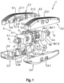
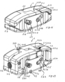
- FIG. 1 A first embodiment of the intervertebral implant according to the invention is shown in the Fig. 1 to Fig. 7a
- the implant 1 has two upper contact bodies 2.1 and 2.2 (2.2 in the Fig. 5a , 6a , 7a removed) and opposite this two lower contact bodies 2.3, 2.4.
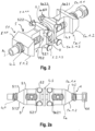
- an actuator or drive mechanism 3 In the middle between these an actuator or drive mechanism 3 is arranged centrally (in particular Fig. 3, 3a ).
- the contact bodies 2.1-2.4 have upwardly or downwardly directed contact surfaces which are essentially horizontally directed in their central region, for example 2.1.1, 2.2.1, 2.3.1, 2.4.1, or form or define a horizontal region, while the contact surfaces slope down or are bent in the longitudinal direction at their ends and opposing upper and lower contact surfaces converge towards each other.
- the drive mechanism 3 has a central threaded body 4 with an axis A, which also determines the longitudinal direction of the implant.
- the threaded body 4 has two threads 4.1, 4.2 arranged one behind the other with opposite directions.
- the thread 4.1 is the distal thread
- the thread 4.2 is the proximal thread.
- the threaded body 4 is designed at the proximal end with an engagement contour 4.4 for engaging a tool (not shown) with which the threaded body 4 can be rotated.
- a guide wheel 4.3 is arranged in the middle of the threaded body 4 and is connected to it in a rotationally fixed manner.
- This guide wheel engages in radially directed transverse slots 2.5 of the contact bodies 2.1-2.4 and thus determines and fixes the relative axial position of the contact bodies 2.1-2.4 and the threaded body 4 to one another - regardless of the lateral and vertical movements of the contact bodies 2.1-2.4 relative to one another.
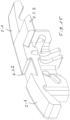
- Double wedges 5, 5a with two ramp parts which have internal threads 5.3 adapted to the threads 4.1, 4.2, are seated on the threaded body 4. These are mirror-imaged and arranged mirror-imaged on both sides of the wheel.
- Each double wedge 5, 5a has a first and a second ramp body 5.1, 5a.1, 5.2, 5a.2, which are each arranged one behind the other in the direction of the axis A and are directed outwards from the wheel 4.3.
- the ramps 5.1.1 and 5.1.2 of the ramp body 5.1 run outwards from the wheel 4 towards each other as follows ( Fig. 2 ):
- the ramp body 5.1 has a ramp 5.1.1 and 5.1.2 as upper and lower ramp surface, each of which has a Surface normal F5 with a finite angle not equal to 90° to a vertical V to the axis A ( Fig. 2, 2a The same applies to the other ramps of the ramp body.
- the contact body 2.1 (and also the contact body 2.2) has a counter surface 2.6 to the ramp 5.1.1 with approximately or exactly the same inclination as the ramps 5.1.1, 5.1.2, against which the ramp 5.1.1 or 5.1.2 acts when the double wedge 5 and the ramp body 5.1 and thus the ramps 5.1.1, 5.1.2 are moved away from the wheel 4.3 along the axis A outwards (to the left in the figure) by twisting the threaded body 4.
- the double wedge 5 has, as mentioned, the ramp body 5.2 with ramps 5.2.1 and 5.2.2, which are vertically aligned (also Fig. 3 ), also running from the wheel 4.3 outwards at an angle to each other and each having a surface normal F5.2 which is directed horizontally, ie perpendicular to the vertical V, and spans a horizontal plane with the axis A ( Fig. 3 ).
- the ramp 5.2.1 acts with a vertically aligned inclined counter surface 2.4.2 on the contact body 2.4 and also with a corresponding counter surface on the front upper contact body 2.3 and can, when the double wedge 5 is moved outwards by turning the threaded body 4 away from the wheel 4.3, move the contact body 2.4 (and also the contact body 2.3) outwards until the ramp 5.2.1 comes out of engagement with the counter surface 2.4.2 (and the corresponding counter surface of the contact body 2.3), so that subsequently, upon further screwing movement of the threaded body 4, the double wedge 5 can move along the contact body 2.4 and also the contact body 2.3.
- the ramp body 5.2 has upper and lower extensions 5.2.1.2 extending laterally from it and beyond the ramps 5.2.1 ( Fig. 2 ), the latter engages in a slot 2.1.4 of the contact body 2.1 and thus guides it horizontally relative to one another during the lateral movement of the contact bodies due to the contact surfaces of the ramp bodies 5.2.
- the slot 2.1.4 has bevels in its area facing the front sides. This guidance is ensured when the contact bodies 2.1 and 2.3 or also 2.2 and 2.4 move apart in the vertical direction under the influence of the ramp bodies 5.1, 5a.1, as described above.
- guide rods 6.1, 6.2 are formed between the contact bodies 2.1 and 2.2, which are displaceable in the two contact bodies 2.1, 2.2 and guide the two contact bodies relative to each other during their lateral movement apart and vertical lifting movement.
- Corresponding guide rods are provided in the lower contact bodies 2.3 and 2.4, which also guide these bodies towards each other during the aforementioned lateral and lowering movements.
- both the upper contact bodies 2.1 and 2.2 and the lower contact bodies 2.3 and 2.4 are first moved apart laterally in a first step by the ramp bodies 5.2 and 5a.2 or their ramps and only then, i.e. at a different time from the aforementioned step, are the contact bodies 2.1 and 2.3 and the contact bodies 2.2 and 2.4 moved apart in a perpendicular or vertical direction by the ramp bodies 5.1 and 5a.1 or the ramps and thus only in the laterally widened state are the contact bodies 2.1-2.4 moved against the upper and lower vertebral bodies, thereby reducing the risk of damage to them.
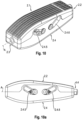
- the embodiment of the intervertebral implant according to the invention is shown in the Fig. 8 to 11a
- This embodiment has basically and largely the same design as the first embodiment of the Fig. 1 to 7a
- identical parts are given the same reference numerals and reference is made to the above description of the first embodiment.
- the main difference from the slightly different design of the ramp bodies 5.2, 5.2a is the double wedge 5, 5a.
- the difference is that instead of the two-sided projections of the corresponding ramp bodies of the design of the Fig. 1 to 7a on each side show a lateral extension 5.2.5 and 5.2.6 of the ramp body 5.2 and 5a.2.6 of the ramp body 5a.2 (the extension present on the other side of the ramp body 5a.2 is not visible in the illustrations).
- the extensions 5.2.5, 5.2.6 and 5a.2.6 are arranged at the middle height of the ramp body 5.2 and 5a.2 respectively. They engage in slots 2.1.5, 2.1.6, 2.2.5, 2.2.6, 2.3.5, 2.3.6, 2.4.5, 2.4.6 which initially run horizontally and then at an angle, with the outer inclined section of the slots 2.1.5, 2.1.6, 2.2.5, 2.2.6 of the upper contact bodies 2.1, 2.2 running downwards towards the outside, while the outer inclined sections of the slots 2.3.5, 2.3.6, 2.4.5, 2.4.6 of the lower contact bodies 2.3, 2.4 running upwards towards the outside.
- the slots must be in the compressed basic configuration ( Fig. 10, 10a ) overlap.
- a horizontal area 2.1.7, 2.2.7 having the slots 2.1.5, 2.1.6 or 2.2.5, 2.2.6 engages in the vertical direction within a side wall of the corresponding lower contact body 2.3 or 2.4 in the interior, which leads to the overlap of the slots in their horizontal area, as in the case of the imaginary combination of the contact bodies 2.1 and 2.3 on the one hand and 2.2 and 2.4 in the Fig. 8 on the other hand, it is readily apparent.
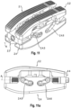
- the Fig. 12 to 16 show a further modification of the intervertebral implant of the previous figures. The same parts are designated with the same reference numerals.
- the intervertebral implant of the Fig. 12 to 16 also has upper contact bodies 2.1, 2.2 and lower contact bodies 2.3, 2.4.
- the intervertebral implant 1 is shown in the compressed state, in the Fig. 13 in a - merely - laterally or horizontally expanded state.
- the implant 1 initially has linear guides 7.1, 7.2 of the two upper contact bodies 2.1, 2.2 ( Fig. 12, 13 ). It also has linear guides 7.3, 7.4 of the two lower contact bodies 2.3, 2.4 ( Fig. 12, 13 , 14 , 16 ).
- the linear guides 7.1-7.4 serve for the lateral or horizontal guidance of the upper contact bodies 2.1, 2.2 and the lower contact bodies 2.3, 2.4 to each other.
- corresponding - vertical - linear guides are provided for the contact bodies 2.1 and 2.3 or 2.2 and 2.4 that are directly above each other, whereby in the illustrations, more precisely in the Fig. 13 , only a vertical linear guide 7.5 of the contact bodies 2.2, 2.4 is shown, which is explained further below.
- Each linear guide 7.1-7.2 consists of a tongue and groove guide, in particular a dovetail guide with Undercuts, such as the latter in particular in the guide 7.3 in the Fig. 12, 13 , 16 , the guides 7.1 and 7.2 of the Fig. 13 and also the Fig. 15 The same applies to guide 7.5 of the Fig. 13 .
- Each linear guide accordingly has a groove and a projection or shoulder engaging in it, usually referred to as a "spring".
- the groove 7.2.1 and the spring or projection 7.2.2 each in particular Fig. 13
- the linear guide 7.3 these are the groove 7.3.1 and the spring 7.3.2 and for the linear guide 7.4, the groove 7.4.1 and the spring 7.4.2 (each Fig. 16 ).
- the - vertical - linear guide 7.5 which is used in the Fig. 13 As shown, the groove is formed between the two downward-leading guide projections 7.5.1 and 7.5.1a and the corresponding tongue or projection of the guide 7.5 is formed by the side wall 7.5.2 of the lower right-hand support body - from the attack side.
- the interacting side walls of the projection or tongue 7.5.2 and the guide projections 7.5.1, 7.5.1a are also dovetail-shaped with undercuts, as shown in the Fig. 13 is evident.
- a vertical linear guide of the superimposed support bodies 2.1, 2.3 is designed in the same way as the linear guide 7.5.
- linear guides ensure that any transverse forces that occur are absorbed by them and, in particular, the double screw 4 and the threads of the wedge body that interact with it are freed from such forces or at least relieved of them.
- the intervertebral body implant 1 is basically introduced and placed in all embodiments in the following manner: First, access to the intervertebral space is established, as is the case in the WO 2014/146797 described.
- the intervertebral implant 1 is then inserted through the access sleeve in its compressed state according to the design of the Fig. 5 This then provides the intermediate configuration of the Fig. 6, 6a
- the insertion sleeve is used to engage an actuating part at the proximal end of the intervertebral implant 1 by means of a tool and the threaded body 4 is rotated via the tool. Since the two double wedges 5, 5a cannot rotate, they are moved away from each other in opposite directions from the starting position by the threaded connection between them and the opposing external threads of the threaded body, as is the case in the transition from the Fig. 2 to Fig. 3 is evident.
- the ramp bodies 5.2 and 5a.2 engage the corresponding counter surfaces of the contact bodies 2.1-2.4 and move them laterally apart until the counter surface of the contact body - for example 2.4.2 - releases the corresponding ramp, so that it can move along the support body when the threaded body 4 is further rotated.
- the ramp body 5.1 with its ramps engages the corresponding counter surfaces - such as 2.6 - of the contact body, so that when the threaded body is further rotated, these are lifted by the two surfaces mentioned until the configuration of the Fig. 7, 7a is reached.
- the contact bodies are moved with their outer side surfaces against the vertebral bodies, thus achieving at least a tensioning of the vertebral body and intervertebral implant.
Landscapes
- Health & Medical Sciences (AREA)
- Engineering & Computer Science (AREA)
- Biomedical Technology (AREA)
- Orthopedic Medicine & Surgery (AREA)
- Neurology (AREA)
- Heart & Thoracic Surgery (AREA)
- Oral & Maxillofacial Surgery (AREA)
- Transplantation (AREA)
- Cardiology (AREA)
- Vascular Medicine (AREA)
- Life Sciences & Earth Sciences (AREA)
- Animal Behavior & Ethology (AREA)
- General Health & Medical Sciences (AREA)
- Public Health (AREA)
- Veterinary Medicine (AREA)
- Prostheses (AREA)
Description
- Die Erfindung betrifft ein Zwischenwirbelimplantat mit mindestens zwei oberen und zwei unteren Kontaktkörpern mit Kontaktflächen, mit einem Aktuator mit einem eine Erstreckungsachse aufweisenden Gewindekörper, der mit hintereinander angeordnete gegenläufigen Gewinden versehen ist, mit auf dem Gewindekörper axial beweglich aufsitzenden, durch Verdrehung desselben entlang diesen verfahrbaren Keilen mit wenigstens an Gegenflächen zumindest eines Teils der Kontaktkörper angreifenden, unter einem endlichen Winkel kleiner 90°aufeinander zu verlaufenden Rampen mindestens eines Rampenkörpers eines Keils.
- Die
US 2019/0269521 A1 zeigt ein gattungsgemäßes Zwischenwirbelimplantat, bei dem einzelne Kontaktkörper des Zwischenimplantats seitlich auseinanderverfahren und in vertikaler Richtung auseinanderbewegt werden können. Das seitliche Auseinanderverfahren geschieht durch einen Aktuator mit einer Gewindestange mit gegenläufigen Gewinden über auf diesen mit Rampen versehenen axial verschiebbaren Gleitkörpern, die an entsprechenden Gegenflächen der Kontaktkörper angreifen. - Das vertikale Auseinanderfahren der Kontaktkörper erfolgt indirekt über zwischen den Keilen und den Tragkörpern angeordneten Zwischenkörpern, die in schräg verlaufenden Nuten der unteren Tragkörper verschiebbar sind.
- Eine derartige Ausgestaltung ist aufgrund der als zusätzlicher bewegbarer Teile vorgesehenen Zwischenkörpern zusätzlich zu den Keilen und den Tragkörpern zum einen aufwendig, zum anderen störanfällig, da hierdurch Verkantungen und Verklemmungen entstehen können.
- Der Erfindung liegt daher die Aufgabe zugrunde, ein Zwischenwirbelimplantat zu schaffen, das unter Vermeidung der vorgenannten Nachteile einfach aufgebaut ist und eine zuverlässige Funktion sicherstellt unter Ermöglichung einer zeitlich versetzten Bewegung der Tragkörper in verschiedene Richtungen.
- Erfindungsgemäß wird die genannte Aufgabe mit einem gattungsgemäßen Zwischenwirbelimplantat gelöst, welches dadurch gekennzeichnet ist, dass die Keile als Doppelkeile mit in Richtung der Erstreckungsachse zwei hintereinander angeordneten Rampenkörper ausgebildet sind und dass die Rampen des einen Rampenkörpers zu den Rampen des anderen Rampenkörpers unterschiedliche Ausrichtung aufweisen und dass die Rampen des ersten Rampenkörpers seitlich direkt an den Kontaktkörpern angreifen, während die Rampen des zweiten Rampenkörpers in vertikaler Richtung direkt an den Kontaktkörpern angreifen.
- Die Erfindung sieht also zwei axial hintereinander angeordnete Rampenkörper mit unterschiedlicher Ausrichtung der Rampen an unterschiedlichen Rampenkörpern am gleichen Doppelkeil vor, wobei der erste Rampenkörper zum lateralen oder seitlichen Auseinanderbewegen der Tragkörper, der zweite Rampenkörper zum Auseinanderbewegen der Tragkörper in vertikaler oder cephalocaudaler Richtung dient.
- Dabei ist insbesondere vorgesehen, dass die Rampen unterschiedlicher Ausrichtung an unterschiedlichen Rampenkörpern eines Doppelkeils angeordnet sind.
- Eine äußerst bevorzugte Ausgestaltung der Erfindung sieht vor, dass die Rampen von ersten Rampenkörpern vertikal mit horizontaler Flächennormale ausgerichtet sind und die Flächennormalen der Rampen von zweiten Rampenkörpern in hierzu unterschiedlicher Ausrichtung einen endlichen Winkel ungleich 90° zur Vertikalen einschließen. Dabei steht eine Weiterbildung vor, dass mit Rampen unterschiedlicher Ausrichtung zusammenwirkende Gegenflächen der Kontaktkörper mit einem gegenüber dem Abstand der Rampenkörper unterschiedlicher Ausrichtung unterschiedlichen Abstand in Erstreckungsrichtung der Achse des Gewindekörpers des Aktuators aufweisen, wobei insbesondere vorgesehen ist, dass der Abstand von Rampen unterschiedlicher Ausrichtung relativ zum Abstand der Gegenflächen an den Kontaktkörpern derart ist, dass bei einer Drehung des Gewindekörpers die Kontaktkörper zumindest lateral auseinanderbewegt und erst anschließend relativ zueinander angehoben werden.
- Dies kann in konkreter Ausgestaltung dadurch erreicht werden, dass der Abstand der Rampen relativ zum Abstand der Gegenflächen derart ist, dass die Kontaktkörper zuerst durch die Rampen des ersten Rampenkörpers seitlich an den Gegenflächen der Kontaktkörper angreifen, um diese lateral auseinander zu bewegen und erst bei weiterer Verdrehung die Rampen des zweiten Rampenkörpers an den Gegenflächen der Kontaktkörper angreifen, um diese anzuheben. Dadurch wird ein zeitlich versetztes Bewegen des Tragkörpers konkret realisiert.
- Auch kann erfindungsgemäß vorgesehen sein, dass der Abstand der Rampen unterschiedlicher Ausrichtung eines Doppelkeils mit zwei Rampenteilen geringer ist als der Abstand der zugehörigen Gegenflächen.
- Weitere bevorzugte Ausgestaltungen der Erfindung sehen vor, dass der Aktuator eine fest mit dem Gewindekörper verbundene radiale Scheibe oder ein radiales Rad aufweist, das in radial zur Achse des Gewindekörpers gerichtete Schlitze der Kontaktkörper zur achssenkrechten Führung derselben eingreift und/oder durch zumindest in den oberen Kontaktkörpern gleitend eingreifende Führungsstäbe zur Führung der Kontaktkörper relativ zueinander.
- Die äußere Kontaktfläche der oberen Kontaktkörper und die untere Außenfläche der unteren Kontaktkörper verlaufen in der Regel nicht parallel zueinander; es ist vielmehr vorzugsweise vorgesehen, dass die äußere Kontaktfläche von oberen Kontaktkörpern zu der äußeren Kontaktfläche der unteren Kontaktkörper einen Winkel zwischen 5° und 15°, vorzugsweise zwischen 9° und 11° einschließen, um so eine bessere Anpassung an die natürliche Lordose zur Lendenwirbelsäule zu erreichen. Dabei beginnt der proximale Bereich der Kontaktflächen jedes einzelnen Kontaktkörpers zunächst in Relation zur horizontalen Mittelebene gesehen mit der Hälfte dieses Winkels linear ansteigenden Flächen und geht dann im distalen Bereich in eine entgegengesetzte Krümmung über, um eine Rundung zu bilden, die auch das Einführen in den Zwischenwirbelraum erleichtert.
- In bevorzugter Ausgestaltung ist vorgesehen, dass die Rampenkörper an einem Doppelkeil einstückig mit diesem ausgebildet sind.
- In einer äußerst bevorzugten Ausgestaltung ist vorgesehen, dass übereinanderliegende und/oder nebeneinanderliegende Kontaktkörper über Linearführungen beweglich zueinander verbunden sind, wobei insbesondere zumindest eine Linearführung eine Nut-Feder-Führung, vorzugsweise eine Schwalbenschwanzführung ist. Durch diese Linearführungen werden bei Scherbelastung auftretende Kräfte durch die Kontaktkörper geleitet und beanspruchen innere (Funktions-) Strukturen, wie den Verschiebemechanismus der Doppelschraube, nicht oder zumindest weniger.
- Weitere Vorteile und Merkmale der Erfindung ergeben sich aus den Ansprüchen und aus der nachfolgenden Beschreibung, in der ein bevorzugtes Ausführungsbeispiel der Erfindung unter Bezugnahme auf die Zeichnung erläutert ist. Dabei zeigt:
- Fig. 1
- Eine Explosionsdarstellung eines ersten erfindungsgemäßen Zwischenwirbelimplantats;
- Fig. 2
- eine perspektivische Darstellung des Antriebsmechanismus des erfindungsgemäßen Implantats der
Fig. 1 im komprimierten Zustand; - Fig. 2a
- eine Seitenansicht des Antriebsmechanismus der
Fig. 2 ; - Fig. 3
- eine perspektivische Darstellung des Antriebsmechanismus der Ausführungsform der
Fig. 1 im expandierten Zustand; - Fig. 3a
- eine Seitenansicht des Antriebsmechanismus entsprechend der
Fig. 3 ; - Fig. 4
- eine perspektivische Darstellung eines Doppelkeils des erfindungsgemäßen Implantats der
Fig. 1 ; - Fig. 4a
- eine Draufsicht auf den Doppelkeil der
Fig. 4 ; - Fig. 4b
- eine Seitenansicht des Doppelkeils der
Fig. 4 ; - Fig. 5
- eine Darstellung des vollständigen Implantats im komprimierten Zustand;
- Fig. 5a
- eine Darstellung des Implantats im komprimierten Zustand mit entferntem oberen vorderen Kontaktkörper;
- Fig. 6
- eine Darstellung des Implantats gemäß einem ersten Schritt lediglich lateral (seitlich) expandiertem Zustand;
- Fig. 6a
- eine Darstellung des Implantats gemäß einem ersten Schritt lediglich lateral (seitlich) expandiertem Zustand gemäß
Fig. 6 mit entferntem oberen vorderen Kontaktkörper; - Fig. 7
- das erfindungsgemäße Implantat im nach dem zweiten Expansionsschritt lateral und vertikal expandiertem Zustand;
- Fig. 7a
- das erfindungsgemäße Implantat im nach dem zweiten Expansionsschritt lateral und vertikal expandiertem Zustand gemäß
Fig. 7 bei entferntem oberen vorderen Tragkörper; - Fig. 8
- eine Explosionsdarstellung einer anderen Ausführungsform des erfindungsgemäßen Zwischenwirbelimplantats;
- Fig. 9
- eine perspektivische Darstellung eines anderen Doppelkeils der Ausgestaltung der
Fig. 8 ; - Fig. 10
- eine perspektivische Darstellung des Implantats der
Fig. 8 im komprimierten Zustand; - Fig. 10a
- eine Seitenansicht des Implantats der
Fig. 8 ,10 im komprimierten Zustand; - Fig. 11
- eine Explosionsdarstellung eines Implantats der
Fig. 8 im vollständig expandierten Zustand; - Fig. 11a
- eine Seitenansicht des Implantats der
Fig. 8 im vollständig expandierten Zustand; und - Fig. 12
- eine abgewandelte Ausführungsform des erfindungsgemäßen Zwischenwirbelimplantats mit Linearführungen in komprimiertem Zustand;
- Fig. 13
- die Ausführungsform der
Fig. 12 in seitlich oder horizontal expandiertem Zustand; - Fig. 14
- eine Seitenansicht des erfindungsgemäßen Zwischenwirbelimplantats der
Fig. 12 im Bereich der - von der Angriffsseite aus gesehen - rechten oberen und unteren Kontaktkörper; - Fig. 15
- eine perspektivische Sicht auf die Innenseite des - von der Angriffsseite aus gesehen - linken oberen Kontaktkörpers; und
- Fig. 16
- eine Sicht von unten auf nebeneinanderliegende untere Kontaktkörper.
- Eine erste Ausführungsform des erfindungsgemäßen Zwischenwirbelimplantats ist in den
Fig. 1 bis Fig. 7a dargestellt. Das Implantat 1 weist zwei obere Kontaktkörper 2.1 und 2.2 (2.2 in denFig. 5a ,6a ,7a entfernt) und diesem gegenüberliegend zwei untere Kontaktkörper 2.3, 2.4 auf. Mittig zwischen diesem ist zentral ein Aktuator oder Antriebsmechanismus 3 angeordnet (insbesondere auchFig. 3, 3a ). - Die Kontaktkörper 2.1-2.4 weisen nach oben bzw. nach unten gerichtete Kontaktflächen auf, die in ihrem Mittelbereich, beispielsweise 2.1.1, 2.2.1, 2.3.1, 2.4.1 im Wesentlichen horizontal gerichtet sind bzw. einen horizontalen Bereich bilden bzw. definieren, während die Kontaktflächen in Längsrichtung an ihren Enden abfallen bzw. gebogen sind und dabei einander gegenüberliegende obere und untere Kontaktflächen aufeinander zu laufen.
- Der Antriebsmechanismus 3 weist einen zentralen Gewindekörper 4 mit einer Achse A auf, die auch die Längsrichtung des Implantats bestimmt. Der Gewindekörper 4 hat zwei hintereinander angeordnete Gewinde 4.1, 4.2 mit gegenläufiger Ausrichtung. Das Gewinde 4.1 ist das distale Gewinde, das Gewinde 4.2 das proximale Gewinde. Der Gewindekörper 4 ist am proximalen Ende mit einer Angriffskontur 4.4 zum Angreifen eines Werkzeugs (nicht dargestellt) ausgebildet, mit dem der Gewindekörper 4 verdreht werden kann. Mittig auf dem Gewindekörper 4 ist drehfest mit diesem verbunden ein Führungsrad 4.3 angeordnet, das in radial gerichtete Querschlitze 2.5 der Kontaktkörper 2.1-2.4 eingreift und derart die relative Axialposition der Kontaktkörper 2.1-2.4 und des Gewindekörpers 4 zueinander bestimmt und festlegt - unabhängig von den lateralen und vertikalen Bewegungen der Kontaktkörper 2.1-2.4 relativ zueinander.
- Auf dem Gewindekörper 4 sitzen mit an die Gewinde 4.1, 4.2 angepassten Innengewinden 5.3 versehene Doppelkeile 5, 5a mit zwei Rampenteilen. Diese sind spiegelbildlich ausgebildet und spiegelbildlich beiderseits des Rads angeordnet.
- Jeder Doppelkeil 5, 5a weist einen ersten und einen zweiten Rampenkörper 5.1, 5a.1, 5.2, 5a.2 auf, die jeweils in Richtung der Achse A hintereinander angeordnet und von dem Rad 4.3 fort nach außen gerichtet sind. Die Rampen 5.1.1 und 5.1.2 des Rampenkörpers 5.1 laufen von dem Rad 4 fort nach außen aufeinander zu und zwar folgendermaßen (
Fig. 2 ): Der Rampenkörper 5.1 weist als obere und untere Rampenfläche jeweils eine Rampe 5.1.1 und 5.1.2 auf, die jeweils eine Flächennormale F5 mit einem endlichen Winkel ungleich 90° zu einer Vertikalen V zur Achse A aufweisen (Fig. 2, 2a ). Für die anderen Rampen der Rampenkörper gilt entsprechendes. - Der Kontaktkörper 2.1 (und ebenso der Kontaktkörper 2.2) weist zur Rampe 5.1.1 eine Gegenfläche 2.6 mit etwa oder genau gleicher Neigung wie die Rampen 5.1.1, 5.1.2 auf, gegen die die Rampe 5.1.1 bzw. 5.1.2 wirkt, wenn unter Verdrehen des Gewindekörpers 4 der Doppelkeil 5 und der Rampenkörper 5.1 und damit die Rampen 5.1.1, 5.1.2 von dem Rad 4.3 fort entlang der Achse A nach außen (in der Abbildung nach links) bewegt wird.
- Für den Rampenkörper 5a.1 und die an diesem befindlichen Rampen 5a.1.1, 5a.1.2 gilt grundsätzlich das Gleiche, wobei auf der Innenseite des Kontaktkörpers 2.1 die entsprechende Gegenfläche 2.1.3 ausgebildet ist. Entsprechendes gilt hinsichtlich der korrespondierenden Rampen des Kontaktkörpers 2.2 und für die untere Rampe 5a.1.2 und entsprechende Gegenflächen der unteren Kontaktkörper 2.3 und 2.4.
- Der Doppelkeil 5 weist zum Rampenkörper 5.1 in Achsrichtung A nach innen versetzt, wie gesagt, den Rampenkörper 5.2 mit Rampen 5.2.1 und 5.2.2 auf, die vertikal ausgerichtet sind (auch
Fig. 3 ), ebenfalls von dem Rad 4.3 nach außen hin schräg aufeinander zu laufen und jeweils eine Flächennormale F5.2 aufweisen, die horizontal gerichtet ist, d.h. senkrecht zur Vertikalen V, und mit der Achse A eine horizontale Ebene aufspannt (Fig. 3 ). - Die Rampe 5.2.1 wirkt mit einer ebenfalls vertikal ausgerichteten schräg verlaufenden Gegenfläche 2.4.2 am Kontaktkörper 2.4 und ebenso mit einer entsprechenden Gegenfläche am vorderen oberen Kontaktkörper 2.3 zusammen und kann, wenn der Doppelkeil 5 durch Drehen des Gewindekörpers 4 von dem Rad 4.3 nach außen fortbewegt wird, derart den Kontaktkörper 2.4 (und auch den Kontaktkörper 2.3) nach außen bewegen, bis die Rampe 5.2.1 außer Eingriff mit der Gegenfläche 2.4.2 (und der entsprechenden Gegenfläche des Kontaktkörpers 2.3) gerät, so dass anschließend bei weiterer Schraubbewegung des Gewindekörpers 4 der Doppelkeil 5 sich entlang des Kontaktkörpers 2.4 und auch des Kontaktkörpers 2.3 bewegen kann.
- Entsprechendes gilt für die Rampe 5.2.2 und die entsprechende Gegenfläche an den Kontaktkörpern 2.1 und 2.2 sowie die korrespondierenden Rampen 5a.2.1, 5a.2.2 des Rampenkörpers 5a.2 am Doppelkeil 5a (
Fig. 3, 3a ), wobei insofern auf die vorstehende Erläuterung hinsichtlich des Zusammenwirkens der Rampe 5.2.1 und der Gegenfläche 2.4.2 verwiesen wird. - In der ersten Ausgestaltung der
Fig. 1-7a weist der Rampenkörper 5.2 sich seitlich von ihm fort und über die Rampen 5.2.1 hinaus erstreckende obere und untere Ansätze 5.2.1.2 auf (Fig. 2 ), so der letztere in einen Schlitz 2.1.4 des Kontaktkörpers 2.1 eingreift und derart diesen bei der lateralen Auseinanderbewegung der Kontaktkörper aufgrund der Kontaktflächen der Rampenkörper 5.2 relativ zueinander horizontal führt. Entsprechendes gilt für die zweiten Ansätze der Rampenkörper 5.2 und 5a.2 und zugeordneten Schlitze 2.3.4 der Kontaktkörper 2.1-2.4. - Der Schlitz 2.1.4 weist in seinem zu den Stirnseiten gerichteten Bereich Abkantungen zueinander auf. Hierdurch wird eine Führung gewährleistet, wenn sich die Kontaktkörper 2.1 und 2.3 bzw. auch 2.2 und 2.4 unter Einwirkung der Rampenkörper 5.1, 5a.1 in vertikaler Richtung auseinanderbewegen, wie dies oben beschrieben wurde.
- Entsprechendes gilt für die aus den Zeichnungen ersichtlichen Ansätze im Bereich des Rampenkörpers 5a.2 und zugeordnete Schlitze wie beispielsweise 2.3.4a., wozu diesbezüglich sowie zu entsprechenden Ansätzen auf der Gegenseite der beiden genannten Rampenkörper und zu entsprechenden Schlitzen in den Kontaktkörpern 2.1 und 2.2 auf die vorstehende Beschreibung verwiesen wird.
- Schließlich sind beispielsweise zwischen den Kontaktkörpern 2.1 und 2.2 noch Führungsstäbe 6.1, 6.2 ausgebildet, die in den beiden Kontaktkörpern 2.1, 2.2 verschieblich sind und die beiden Kontaktkörper bei ihrer lateralen Auseinanderbewegung und vertikalen Hubbewegung relativ zueinander führen.
- Entsprechende Führungsstäbe sind in den unteren Kontaktkörpern 2.3 und 2.4 vorgesehen, die diese Körper bei der genannten lateralen und einer Absenkbewegung ebenfalls zueinander führen.
- Den Figuren, insbesondere der
Fig. 1 ist zu entnehmen, dass der axiale Abstand vom Rampenkörper 5.2 und damit dessen Rampe 5.2.1 zum Rampenkörper 5.1 bzw. dessen Rampe 5.1.1 (und den entsprechenden nicht sichtbaren Rampen) geringer ist als der axiale Abstand zwischen der Gegenfläche 2.4.2 und der Gegenfläche 2.6 bzw. der entsprechenden Gegenfläche des jeweils gleichen Kontaktkörpers. Entsprechendes gilt für den Abstand der Rampenkörper 5a.2 und 5a.1 bzw. deren Rampen im Verhältnis zu den entsprechenden Gegenflächen an den Kontaktkörpern. - Damit wird erreicht, dass sowohl die oberen Kontaktkörper 2.1 und 2.2 als auch die unteren Kontaktkörper 2.3 und 2.4 zunächst in einem ersten Schritt durch die Rampenkörper 5.2 und 5a.2 bzw. deren Rampen lateral seitlich auseinandergefahren werden und erst anschließend, also zeitlich versetzt zu dem vorgenannten Schritt, die Kontaktkörper 2.1 und 2.3 sowie die Kontaktkörper 2.2 und 2.4 durch die Rampenkörper 5.1 und 5a.1 bzw. den Rampen in senkrechter bzw. vertikaler Richtung auseinandergefahren werden und damit erst im lateral verbreiterten Zustand die Kontaktkörper 2.1-2.4 gegen den oberen und unteren Wirbelkörper verfahren werden, wodurch die Gefahr einer Beschädigung derselben reduziert wird.
- Die Ausführungsform des erfindungsgemäßen Zwischenwirbelimplantats ist in den
Fig. 8 bis 11a dargestellt. Diese Ausführungsform weist grundsätzlich und weitgehend die gleiche Ausgestaltung wie die erste Ausführungsform derFig. 1 bis 7a auf. Insofern werden gleiche Teile mit gleichen Bezugszeichen versehen und es wird zur Beschreibung auf die vorstehende Beschreibung der ersten Ausführungsform verwiesen. Der wesentliche Unterschied aus der etwas anderen Ausgestaltung der Rampenkörper 5.2, 5.2a ist der Doppelkeil 5, 5a. Der Unterschied liegt darin, dass diese statt der zweiseitlichen Ansätze der entsprechenden Rampenkörper der Ausgestaltung derFig. 1 bis 7a auf jeder Seite einen seitlichen Ansatz 5.2.5 und 5.2.6 des Rampenkörpers 5.2 und 5a.2.6 des Rampenkörpers 5a.2 zeigen (der auf der anderen Seite am Rampenkörper 5a.2 vorhandene Ansatz ist in den Darstellungen nicht ersichtlich). Die Ansätze 5.2.5, 5.2.6 und 5a.2.6 sind auf mittlerer Höhe des Rampenkörpers 5.2 bzw. 5a.2 angeordnet. Sie greifen in zunächst horizontal, dann schräg verlaufende Schlitze 2.1.5, 2.1.6, 2.2.5, 2.2.6, 2.3.5, 2.3.6, 2.4.5, 2.4.6 ein, wobei der äußere geneigte Abschnitt der Schlitze 2.1.5, 2.1.6, 2.2.5, 2.2.6 der oberen Kontaktkörper 2.1, 2.2 nach außen hin abwärts verläuft, während die äußeren geneigten Abschnitte der Schlitze 2.3.5, 2.3.6, 2.4.5, 2.4.6 der unteren Kontaktkörper 2.3, 2.4 nach außen hin aufwärts verlaufen. - Dies bewirkt, dass wenn die Ansätze 5.2.5 und 5.2.6 (sowie die entsprechenden Ansätze des Rampenkörpers 5a) in die geneigten Abschnitte der genannten Schlitze eintreten die unteren Kontaktkörper 2.3 und 2.4 nach unten und die oberen Kontaktkörper 2.1 und 2.2 nach oben gedrückt werden und damit eine vertikale Spreizung bewirkt wird. Die vorangehende horizontale Spreizung der Kontaktkörper 2.1 und 2.2 relativ zueinander und 2.3 sowie 2.4 relativ zueinander erfolgt in der gleichen Weise, wie unter Bezug auf die erste Ausgestaltung beschrieben.
- Damit die Ansätze 5.2.5 und 5.2.6 sowie auch 5a.2.6 (und der entsprechende gegenüberliegende Ansatz des Rampenkörpers 5a.2) jeweils in einen Schlitz eines unteren Kontaktkörpers und eines oberen Kontaktkörpers gleichzeitig eingreifen können, um die entsprechenden Vertikalspreizungen zu bewegen, also beispielsweise der Ansatz 5.2.5 sowohl in den Schlitz 2.3.5 des Kontaktkörpers 2.3 als auch in den Schlitz 2.1.5 des Kontaktkörpers 2.1 müssen die Schlitze sich in der komprimierten Grundkonfiguration (
Fig. 10, 10a ) überlappen. Demgemäß greift ein die Schlitze 2.1.5, 2.1.6 bzw. 2.2.5, 2.2.6 aufweisender horizontaler Bereich 2.1.7, 2.2.7 in vertikaler Richtung innerhalb einer Seitenwandung des entsprechenden unteren Kontaktkörpers 2.3 bzw. 2.4 im Inneren ein, wodurch es zur Überlagerung der Schlitze in ihrem horizontalen Bereich kommt, wie bei gedanklicher Zusammenführung der Kontaktkörper 2.1 und 2.3 einerseits und 2.2 und 2.4 in derFig. 8 andererseits ohne weiteres ersichtlich. - Die
Fig. 12 bis 16 zeigen eine weitere Abwandlung des Zwischenwirbelimplantats der vorangehenden Figuren. Gleiche Teile sind mit gleichen Bezugszeichen bezeichnet. Das Zwischenwirbelimplantat derFig. 12 bis 16 weist ebenfalls obere Kontaktkörper 2.1, 2.2 und untere Kontaktkörper 2.3, 2.4 auf. In derFig. 12 ist das Zwischenwirbelimplantat 1 im komprimierten Zustande dargestellt, in derFig. 13 in einem - lediglich - seitlich oder horizontal expandierten Zustand. - Das Implantat 1 weist zunächst Linearführungen 7.1, 7.2 der beiden oberen Kontaktkörper 2.1, 2.2 auf (
Fig. 12, 13 ). Weiter weist es Linearführungen 7.3, 7.4 der beiden unteren Kontaktkörper 2.3, 2.4 auf (Fig. 12, 13 ,14 ,16 ). Die Linearführungen 7.1-7.4 dienen zur seitlichen oder horizontalen Führung jeweils der oberen Kontaktkörper 2.1, 2.2 bzw. der unteren Kontaktkörper 2.3, 2.4 zueinander. Weiter sind entsprechende - vertikale - Linearführungen der unmittelbar übereinanderliegenden Kontaktkörper 2.1 und 2.3 bzw. 2.2 und 2.4 vorgesehen, wobei in den Abbildungen, genauer in derFig. 13 , lediglich eine vertikale Linearführung 7.5 der Kontaktkörper 2.2, 2.4 dargestellt ist, die weiter unten erläutert wird. - Jede Linearführung 7.1-7.2 besteht aus einer Nut-Feder-Führung, insbesondere einer Schwalbenschwanzführung mit Hinterschneidungen, wie dies letztere insbesondere bei der Führung 7.3 in den
Fig. 12, 13 ,16 , den Führungen 7.1 und 7.2 derFig. 13 und auch derFig. 15 dargestellt und ersichtlich ist. Entsprechendes gilt auch für die Führung 7.5 derFig. 13 . - Jede Linearführung weist demgemäß eine Nut und einen in diesen eingreifenden, üblicherweise als "Feder" bezeichneten Vorsprung oder Ansatz auf. Bei der Linearführung 7.1 sind dies die Nut 7.1.1 und die Feder 7.1.2, bei der Linearführung 7.2 die Nut 7.2.1 und die Feder oder der Vorsprung 7.2.2 (jeweils insbesondere
Fig. 13 ). Bei der Linearführung 7.3 sind dies die Nut 7.3.1 und die Feder 7.3.2 und bei der Linearführung 7.4 die Nut 7.4.1 und die Feder 7.4.2 (jeweilsFig. 16 ). - Bei der - vertikalen - Linearführung 7.5, die in der
Fig. 13 dargestellt ist, ist die Nut zwischen den beiden nach unten führenden Führungsvorsprüngen 7.5.1 und 7.5.1a gebildet und die entsprechende Feder oder der Vorsprung der Führung 7.5 wird durch die Seitenwandung 7.5.2 des - von der Angriffsseite aus - rechten unteren Tragkörpers gebildet. Dabei sind die miteinander zusammenwirkenden Seitenwandungen des Vorsprungs oder der Feder 7.5.2 und der Führungsvorsprünge 7.5.1, 7.5.1a ebenfalls schwalbenschwanzförmig mit Hinterschneidungen ausgebildet, wie dies in derFig. 13 ersichtlich ist. - Eine vertikale Linearführung der übereinanderliegenden Tragköper 2.1, 2.3 ist in gleicher Weise ausgebildet wie die Linearführung 7.5.
- Durch die Linearführungen wird erreicht, dass auftretende Querkräfte durch diese aufgenommen werden und insbesondere die Doppelschraube 4 und mit diesen zusammenwirkenden Gewinden der Keilkörper von solchen Kräften befreit oder zumindest entlastet werden.
- Das erfindungsgemäße Zwischenwirbelkörperimplantat 1 wird in allen Ausführungsformen grundsätzlich in folgender Weise eingeführt und platziert:
Zunächst wird ein Zugang zum Zwischenwirbelkörperfach gelegt, wie dies beispielsweise in derWO 2014/146797 beschrieben ist. - Durch die Zugangshülse wird dann das Zwischenwirbelimplantat 1 in seinem komprimierten Zustand entsprechend der Ausgestaltung der
Fig. 5 eingeführt. Damit ist dann die Zwischenkonfiguration derFig. 6, 6a erreicht. Wenn das Zwischenwirbelimplantat 1 seine Position zwischen den beiden Wirbeln, einem unter ihm befindlichen und einem über ihm befindlichen Wirbel erreicht hat, wird durch die Einführhülse mittels eines Werkzeugs an einem Betätigungsteil am proximalen Ende des Zwischenwirbelimplantats 1 angegriffen und über das Werkzeug der Gewindekörper 4 verdreht. Da die beiden Doppelkeile 5, 5a sich nicht mitdrehen können, werden sie durch die Gewindeverbindung zwischen ihnen und den entgegengerichteten Außengewinden des Gewindekörpers aus der Ausgangsposition in entgegengesetzter Richtung voneinander fortbewegt, wie dies im Übergang von derFig. 2 zurFig. 3 ersichtlich ist. - Dabei greifen zunächst die Rampenkörper 5.2 und 5a.2 an den entsprechenden Gegenflächen der Kontaktkörper 2.1-2.4 an und verfahren diese lateral auseinander, bis die Gegenfläche der Kontaktkörper - beispielsweise 2.4.2 - die entsprechende Rampe freigibt, so dass sie beim weiteren Verdrehen des Gewindekörpers 4 sich entlang des Tragkörpers bewegen kann. Gleichzeitig - d.h. nach vollständigem lateralen Auseinanderfahren der Tragkörper - greift der Rampenkörper 5.1 mit seinen Rampen an den entsprechenden Gegenflächen - wie 2.6 - der Kontaktkörper an, so dass beim weiteren Verdrehen des Gewindekörpers diese durch die beiden genannten Flächen angehoben werden, bis die Konfiguration der
Fig. 7, 7a erreicht ist. - Bei diesem letzten Verfahrensschritt werden die Kontaktkörper mit ihren äußeren Seitenflächen gegen die Wirbelkörper verfahren und damit zumindest eine Verspannung der Teile Wirbelkörper und Zwischenwirbelimplantat erreicht.
- Dadurch, dass die Kontaktkörper erst im lateral gespreizten Zustand gegen die Wirbelkörper verfahren, wird die Gefahr einer Beschädigung derselben wesentlich reduziert bzw. ausgeschlossen.
Claims (13)
- Zwischenwirbelimplantat- mit mindestens zwei oberen und zwei unteren Kontaktkörpern (2.1-2.4) mit Kontaktflächen (2.1.1-2.4.1),- mit einem Aktuator (3) mit einem eine Erstreckungsachse (A) aufweisenden Gewindekörper (4), der mit hintereinander angeordneten gegenläufigen Gewinden (4.1, 4.2) versehen ist,- mit auf dem Gewindekörper (4) axial beweglich aufsitzenden, durch Verdrehung desselben entlang diesem verfahrbaren Keilen mit wenigstens an Gegenflächen zumindest eines Teils der Kontaktkörper angreifenden, unter einem endlichen Winkel kleiner 90°aufeinander zu verlaufenden Rampen (5.2.1, 5a.2.1) mindestens eines Rampenkörpers (5.2, 5a.2) eines Keils,
dadurch gekennzeichnet,- dass die Keile als Doppelkeile mit in Richtung der Erstreckungsachse (A) zwei hintereinander angeordnete Rampenkörper ausgebildet sind,- dass die Rampen (5.1.1, 5.1.2; 5a.1.1, 5a.1.2) des einen Rampenkörpers (5.1, 5.2,) zu den Rampen (5.2.1, 5.2.2, 5a.2.1, 5a.2.2) des anderen Rampenkörpers (5a.1, 5a.2) unterschiedliche Ausrichtung aufweisen.- dass die Rampen (5.2.1, 5.2.2; 5a.2.1, 5a.2.2) des ersten Rampenkörpers (5.2, 5a.2) seitlich direkt an den Kontaktkörpern (2.1-2.4) angreifen, während die Rampen (5.1.1, 5.1.2; 5a.1.1, 5a.1.2) des zweiten Rampenkörpers (5.1, 5a.1) in vertikaler Richtung direkt an den Kontaktkörpern (2.1-2.4) angreifen. - Zwischenwirbelimplantat nach Anspruch 1, dadurch gekennzeichnet, dass die Rampen (5.2.1, 5a.2.1) von ersten Rampenkörpern (5.2, 5a.2) vertikal mit horizontaler Flächennormale (H) ausgerichtet sind und die Flächennormalen (F) der Rampen (5.1.1, 5a.1.1) von zweiten Rampenkörpern (5.1, 5a.1) in hierzu unterschiedlicher Ausrichtung einen endlichen Winkel ungleich 90° zur Vertikalen (V) einschließen.
- Zwischenwirbelimplantat nach Anspruch 1 oder 2, dadurch gekennzeichnet, dass die Rampen (5.1.1, 5.2.1 bzw. 5a.1.1, 5a.2.1) unterschiedlicher Ausrichtung an unterschiedlichen Rampenkörpern (5.1, 5.2 bzw. 5a.1, 5a.2) angeordnet sind.
- Zwischenwirbelimplantat nach einem der Ansprüche 1 bis 3, dadurch gekennzeichnet, dass mit Rampen (5.1.1, 5.2.1; 5a.1.1, 5a.2.1) unterschiedlicher Ausrichtung unterschiedliche Ausrichtung zusammenwirkende Gegenflächen (2.4.2, 2.6) der Kontaktkörper (2.1-2.4) mit einem gegenüber dem Abstand der Rampenkörper (5.1, 5.2, 5a.1, 5a.2) unterschiedlicher Ausrichtung unterschiedlichen Abstand in Erstreckungsrichtung der Achse (A) des Gewindekörpers (4) des Aktuators aufweisen.
- Zwischenwirbelimplantat nach einem der vorangehenden Ansprüche, dadurch gekennzeichnet, dass der Abstand von Rampen (5.1.1, 5.2.1; 5a.1.1, 5a.2.2) unterschiedlicher Ausrichtung relativ zum Abstand der Gegenflächen (2.4.2, 2.6) an den Kontaktkörpern (2.1-2.4) derart ist, dass bei einer Drehung des Gewindekörpers (4) die Kontaktkörper (2.1-2.4) zumindest lateral auseinanderbewegt und erst anschließend relativ zueinander angehoben werden.
- Zwischenwirbelimplantat nach einem vorangehenden Ansprüche, dadurch gekennzeichnet, dass der Abstand der Rampen (5.1.1, 5.2.1; 5a.1.1, 5a.2.1) relativ zum Abstand der Gegenflächen (2.4.2, 2.6) derart ist, dass die Kontaktkörper (2.1-2.4) zuerst durch die Rampen (5.2.1, 5a.2.1) des ersten Rampenkörpers (5.2, 5a.2) seitlich an den Gegenflächen (2.4.2) der Kontaktkörper (2.1-2.4) angreifen, um diese lateral auseinander zu bewegen und erst bei weiterer Verdrehung die Rampen (5.1.1, 5a.1.1) des zweiten Rampenkörpers (5.1, 5a.1) an den Gegenflächen (2.6) der Kontaktkörper (2.1-2.4) angreifen, um diese anzuheben.
- Zwischenwirbelimplantat nach einem der vorangehenden Ansprüche, dadurch gekennzeichnet, dass der Abstand der Rampen unterschiedlicher Ausrichtung (5.1.1, 5.2.1; 5a.1.1, 5a.2.1) eines Doppelkeils (5 bzw. 5a) geringer ist als der Abstand der zugehörigen Gegenflächen (2.4.1, 2.6).
- Zwischenwirbelimplantat nach einem der vorangehenden Ansprüche, dadurch gekennzeichnet, dass der Aktuator eine fest mit dem Gewindekörper verbundene radiale Scheibe oder ein radiales Rad (4.3) aufweist, das in radial zur Achse (A) des Gewindekörpers (4) gerichtete Schlitze (2.5) der Kontaktkörper (2.1-2.4) zur achssenkrechten Führung derselben eingreift.
- Zwischenwirbelimplantat nach einem der vorangehenden Ansprüche, gekennzeichnet durch zumindest in den oberen Kontaktkörpern (2.1, 2.2) gleitend eingreifende Führungsstäbe zur Führung der Kontaktkörper (2.1, 2.2) relativ zueinander.
- Zwischenwirbelimplantat nach einem der vorangehenden Ansprüche, dadurch gekennzeichnet, dass die äußere Kontaktfläche von oberen Kontaktkörpern (2.1, 2.2) zu der äußeren Kontaktfläche der unteren Kontaktkörper (2.3, 2.4) einen Winkel zwischen 5° und 15°, vorzugsweise zwischen 9° und 11° einschließen.
- Zwischenwirbelimplantat, dadurch gekennzeichnet, dass die Rampenkörper (5.1, 5.2, 5a.1, 5a.2) an einem Doppelkeil einstückig mit diesem ausgebildet sind.
- Zwischenwirbelimplantat nach einem der vorangehenden Ansprüche, dadurch gekennzeichnet, dass übereinanderliegende und/oder nebeneinanderliegende Kontaktkörper (2.1, 2.3; 2.2, 2.4 bzw. 2.1, 2.2; 2.3, 2.4) über Linearführungen beweglich zueinander verbunden sind.
- Zwischenwirbelimplantat nach Anspruch 12, dadurch gekennzeichnet, dass zumindest eine Linearführung eine Nut-Feder-Führung, vorzugsweise eine Schwalbenschwanzführung ist.
Applications Claiming Priority (2)
| Application Number | Priority Date | Filing Date | Title |
|---|---|---|---|
| DE102020000319.2A DE102020000319A1 (de) | 2020-01-21 | 2020-01-21 | Zwischenwirbelimplantat |
| PCT/EP2021/050788 WO2021148316A1 (de) | 2020-01-21 | 2021-01-15 | Zwischenwirbelimplantat |
Publications (3)
| Publication Number | Publication Date |
|---|---|
| EP3905992A1 EP3905992A1 (de) | 2021-11-10 |
| EP3905992C0 EP3905992C0 (de) | 2025-02-19 |
| EP3905992B1 true EP3905992B1 (de) | 2025-02-19 |
Family
ID=74494863
Family Applications (1)
| Application Number | Title | Priority Date | Filing Date |
|---|---|---|---|
| EP21702593.1A Active EP3905992B1 (de) | 2020-01-21 | 2021-01-15 | Zwischenwirbelimplantat |
Country Status (10)
| Country | Link |
|---|---|
| US (1) | US12171668B2 (de) |
| EP (1) | EP3905992B1 (de) |
| JP (1) | JP7745266B2 (de) |
| KR (1) | KR20220130135A (de) |
| CN (1) | CN115151222B (de) |
| AU (1) | AU2021211853B2 (de) |
| CA (1) | CA3163303A1 (de) |
| DE (1) | DE102020000319A1 (de) |
| ES (1) | ES3024758T3 (de) |
| WO (1) | WO2021148316A1 (de) |
Families Citing this family (3)
| Publication number | Priority date | Publication date | Assignee | Title |
|---|---|---|---|---|
| US9566168B2 (en) * | 2010-09-03 | 2017-02-14 | Globus Medical, Inc. | Expandable fusion device and method of installation thereof |
| KR102823085B1 (ko) * | 2023-04-27 | 2025-06-19 | 국립한국교통대학교산학협력단 | 확장형 케이지 |
| US12396866B2 (en) | 2023-09-27 | 2025-08-26 | Globus Medical, Inc. | Expandable anterior lumbar implants |
Family Cites Families (12)
| Publication number | Priority date | Publication date | Assignee | Title |
|---|---|---|---|---|
| AU2003240354A1 (en) * | 2003-06-24 | 2005-01-04 | Synthes Gmbh | Implant for the intervertebral space |
| JP4299835B2 (ja) * | 2003-07-22 | 2009-07-22 | ジンテーズ ゲゼルシャフト ミト ベシュレンクテル ハフツング | 一時的遮断手段を有する椎間インプラント |
| US9155628B2 (en) | 2009-10-15 | 2015-10-13 | Globus Medical, Inc. | Expandable fusion device and method of installation thereof |
| US9320610B2 (en) | 2011-08-16 | 2016-04-26 | Stryker European Holdings I, Llc | Expandable implant |
| JP6412551B2 (ja) | 2013-03-11 | 2018-10-24 | グローバス メディカル インコーポレイティッド | 拡張可能な融合装置及びその設置方法 |
| DE102013004964B4 (de) | 2013-03-22 | 2016-11-03 | Joimax Gmbh | Instrumentenset und Verfahren zum Einbringen eines Körbchens in das Bandscheibenfach zwischen zwei Wirbelkörpern |
| US11426290B2 (en) | 2015-03-06 | 2022-08-30 | DePuy Synthes Products, Inc. | Expandable intervertebral implant, system, kit and method |
| US11033401B2 (en) | 2017-01-10 | 2021-06-15 | Integrity Implants Inc. | Expandable intervertebral fusion device |
| US10398563B2 (en) * | 2017-05-08 | 2019-09-03 | Medos International Sarl | Expandable cage |
| EP3742990A4 (de) | 2018-03-01 | 2021-11-24 | Integrity Implants Inc. | Expandierbare fusionsvorrichtung mit unabhängigen expansionssystemen |
| KR20200060906A (ko) * | 2018-11-23 | 2020-06-02 | 주식회사 앤트스파인 | 네 방향 확장형 추간체 유합 케이지 장치 |
| US11166826B2 (en) * | 2019-11-13 | 2021-11-09 | Ossaware Biotech Co., Ltd. | Multi-section expandable device |
-
2020
- 2020-01-21 DE DE102020000319.2A patent/DE102020000319A1/de active Pending
-
2021
- 2021-01-15 AU AU2021211853A patent/AU2021211853B2/en active Active
- 2021-01-15 EP EP21702593.1A patent/EP3905992B1/de active Active
- 2021-01-15 ES ES21702593T patent/ES3024758T3/es active Active
- 2021-01-15 JP JP2022541933A patent/JP7745266B2/ja active Active
- 2021-01-15 WO PCT/EP2021/050788 patent/WO2021148316A1/de not_active Ceased
- 2021-01-15 CN CN202180010255.4A patent/CN115151222B/zh active Active
- 2021-01-15 CA CA3163303A patent/CA3163303A1/en active Pending
- 2021-01-15 KR KR1020227025457A patent/KR20220130135A/ko active Pending
-
2022
- 2022-07-20 US US17/869,505 patent/US12171668B2/en active Active
Also Published As
| Publication number | Publication date |
|---|---|
| AU2021211853B2 (en) | 2025-10-16 |
| AU2021211853A1 (en) | 2022-08-18 |
| EP3905992C0 (de) | 2025-02-19 |
| JP7745266B2 (ja) | 2025-09-29 |
| KR20220130135A (ko) | 2022-09-26 |
| EP3905992A1 (de) | 2021-11-10 |
| ES3024758T3 (en) | 2025-06-05 |
| CN115151222B (zh) | 2025-10-17 |
| CA3163303A1 (en) | 2021-07-29 |
| US20220395379A1 (en) | 2022-12-15 |
| CN115151222A (zh) | 2022-10-04 |
| DE102020000319A1 (de) | 2021-07-22 |
| JP2023510262A (ja) | 2023-03-13 |
| WO2021148316A1 (de) | 2021-07-29 |
| US12171668B2 (en) | 2024-12-24 |
Similar Documents
| Publication | Publication Date | Title |
|---|---|---|
| EP1694257B1 (de) | Längenverstellbares wirbelsäulen-implantat | |
| DE10065398C2 (de) | Längenverstellbarer Platzhalter zum Einsetzen zwischen zwei Wirbelkörper | |
| EP1411871B1 (de) | Platzhalter mit veränderbarer axialer länge | |
| DE19804765C2 (de) | Platzhalter mit einstellbarer axialer Länge | |
| EP3905992B1 (de) | Zwischenwirbelimplantat | |
| EP2114274B1 (de) | Plattenimplantat, insbesondere für die anwendung an einer wirbelsäule | |
| WO2005030066A1 (de) | Vorrichtung zur elastischen stabilisieung von wirbelkörpern | |
| WO1996016607A1 (de) | Befestigungselement für die osteosynthese | |
| EP1394012B1 (de) | Verriegelungsvorrichtung für zwei relativ zueinander verschiebbar gelagerte Bauteile | |
| EP0928602A2 (de) | Scherwerkzeug für Implantate | |
| DE3629068A1 (de) | Einrichtung zur einstellung einer torsionsspannung | |
| EP3721102B1 (de) | Zweiteilige schraubenmutter mit hoher andrückkraft | |
| EP3043011B1 (de) | Schliesszylinder mit plättchenzuhaltungen für ein zylinderschloss sowie zylinderschloss mit einem derartigen schliesszylinder | |
| WO2014131617A1 (de) | Herstellungsverfahren für schrauben und betonschraube | |
| EP2792429B1 (de) | Axialgewinderollkopf und Verfahren zum Formen eines Außengewindes an einem Werkstück mit einem Axialgewinderollkopf | |
| WO2011147039A1 (de) | Gelenklager | |
| DE202017105466U1 (de) | Implantat zur intersomatischen Wirbelfusion | |
| EP3919683B1 (de) | Verbindungsvorrichtung | |
| DE102007033219B4 (de) | Orthopädisches Haltesystem | |
| AT200395B (de) | Vorrichtung zum oeffnen von briefen | |
| AT500716A1 (de) | Verfahren zur ausgestaltung eines verbindungselementes und verbindungselement | |
| EP1183114A1 (de) | Biegedorn für eine biegevorrichtung und biegeverfahren für rohre | |
| DE202007009970U1 (de) | Orthopädisches Haltesystem | |
| DE4039402A1 (de) | Schraube mit selbstsicherndem gewinde | |
| EP2434080B1 (de) | Asymetrische Achsklemmung |
Legal Events
| Date | Code | Title | Description |
|---|---|---|---|
| STAA | Information on the status of an ep patent application or granted ep patent |
Free format text: STATUS: UNKNOWN |
|
| STAA | Information on the status of an ep patent application or granted ep patent |
Free format text: STATUS: THE INTERNATIONAL PUBLICATION HAS BEEN MADE |
|
| PUAI | Public reference made under article 153(3) epc to a published international application that has entered the european phase |
Free format text: ORIGINAL CODE: 0009012 |
|
| STAA | Information on the status of an ep patent application or granted ep patent |
Free format text: STATUS: REQUEST FOR EXAMINATION WAS MADE |
|
| 17P | Request for examination filed |
Effective date: 20210803 |
|
| AK | Designated contracting states |
Kind code of ref document: A1 Designated state(s): AL AT BE BG CH CY CZ DE DK EE ES FI FR GB GR HR HU IE IS IT LI LT LU LV MC MK MT NL NO PL PT RO RS SE SI SK SM TR |
|
| DAV | Request for validation of the european patent (deleted) | ||
| DAX | Request for extension of the european patent (deleted) | ||
| GRAP | Despatch of communication of intention to grant a patent |
Free format text: ORIGINAL CODE: EPIDOSNIGR1 |
|
| STAA | Information on the status of an ep patent application or granted ep patent |
Free format text: STATUS: GRANT OF PATENT IS INTENDED |
|
| GRAJ | Information related to disapproval of communication of intention to grant by the applicant or resumption of examination proceedings by the epo deleted |
Free format text: ORIGINAL CODE: EPIDOSDIGR1 |
|
| STAA | Information on the status of an ep patent application or granted ep patent |
Free format text: STATUS: REQUEST FOR EXAMINATION WAS MADE |
|
| INTG | Intention to grant announced |
Effective date: 20240823 |
|
| INTC | Intention to grant announced (deleted) | ||
| GRAP | Despatch of communication of intention to grant a patent |
Free format text: ORIGINAL CODE: EPIDOSNIGR1 |
|
| STAA | Information on the status of an ep patent application or granted ep patent |
Free format text: STATUS: GRANT OF PATENT IS INTENDED |
|
| INTG | Intention to grant announced |
Effective date: 20241023 |
|
| GRAS | Grant fee paid |
Free format text: ORIGINAL CODE: EPIDOSNIGR3 |
|
| GRAA | (expected) grant |
Free format text: ORIGINAL CODE: 0009210 |
|
| STAA | Information on the status of an ep patent application or granted ep patent |
Free format text: STATUS: THE PATENT HAS BEEN GRANTED |
|
| AK | Designated contracting states |
Kind code of ref document: B1 Designated state(s): AL AT BE BG CH CY CZ DE DK EE ES FI FR GB GR HR HU IE IS IT LI LT LU LV MC MK MT NL NO PL PT RO RS SE SI SK SM TR |
|
| REG | Reference to a national code |
Ref country code: GB Ref legal event code: FG4D Free format text: NOT ENGLISH |
|
| REG | Reference to a national code |
Ref country code: CH Ref legal event code: EP |
|
| REG | Reference to a national code |
Ref country code: IE Ref legal event code: FG4D Free format text: LANGUAGE OF EP DOCUMENT: GERMAN |
|
| REG | Reference to a national code |
Ref country code: DE Ref legal event code: R096 Ref document number: 502021006692 Country of ref document: DE |
|
| U01 | Request for unitary effect filed |
Effective date: 20250317 |
|
| U07 | Unitary effect registered |
Designated state(s): AT BE BG DE DK EE FI FR IT LT LU LV MT NL PT RO SE SI Effective date: 20250324 |
|
| REG | Reference to a national code |
Ref country code: ES Ref legal event code: FG2A Ref document number: 3024758 Country of ref document: ES Kind code of ref document: T3 Effective date: 20250605 |
|
| PG25 | Lapsed in a contracting state [announced via postgrant information from national office to epo] |
Ref country code: RS Free format text: LAPSE BECAUSE OF FAILURE TO SUBMIT A TRANSLATION OF THE DESCRIPTION OR TO PAY THE FEE WITHIN THE PRESCRIBED TIME-LIMIT Effective date: 20250519 |
|
| PG25 | Lapsed in a contracting state [announced via postgrant information from national office to epo] |
Ref country code: PL Free format text: LAPSE BECAUSE OF FAILURE TO SUBMIT A TRANSLATION OF THE DESCRIPTION OR TO PAY THE FEE WITHIN THE PRESCRIBED TIME-LIMIT Effective date: 20250219 |
|
| PG25 | Lapsed in a contracting state [announced via postgrant information from national office to epo] |
Ref country code: IS Free format text: LAPSE BECAUSE OF FAILURE TO SUBMIT A TRANSLATION OF THE DESCRIPTION OR TO PAY THE FEE WITHIN THE PRESCRIBED TIME-LIMIT Effective date: 20250619 Ref country code: NO Free format text: LAPSE BECAUSE OF FAILURE TO SUBMIT A TRANSLATION OF THE DESCRIPTION OR TO PAY THE FEE WITHIN THE PRESCRIBED TIME-LIMIT Effective date: 20250519 |
|
| PG25 | Lapsed in a contracting state [announced via postgrant information from national office to epo] |
Ref country code: HR Free format text: LAPSE BECAUSE OF FAILURE TO SUBMIT A TRANSLATION OF THE DESCRIPTION OR TO PAY THE FEE WITHIN THE PRESCRIBED TIME-LIMIT Effective date: 20250219 |
|
| PG25 | Lapsed in a contracting state [announced via postgrant information from national office to epo] |
Ref country code: GR Free format text: LAPSE BECAUSE OF FAILURE TO SUBMIT A TRANSLATION OF THE DESCRIPTION OR TO PAY THE FEE WITHIN THE PRESCRIBED TIME-LIMIT Effective date: 20250520 |
|
| PG25 | Lapsed in a contracting state [announced via postgrant information from national office to epo] |
Ref country code: SM Free format text: LAPSE BECAUSE OF FAILURE TO SUBMIT A TRANSLATION OF THE DESCRIPTION OR TO PAY THE FEE WITHIN THE PRESCRIBED TIME-LIMIT Effective date: 20250219 |
|
| PG25 | Lapsed in a contracting state [announced via postgrant information from national office to epo] |
Ref country code: CZ Free format text: LAPSE BECAUSE OF FAILURE TO SUBMIT A TRANSLATION OF THE DESCRIPTION OR TO PAY THE FEE WITHIN THE PRESCRIBED TIME-LIMIT Effective date: 20250219 |
|
| PG25 | Lapsed in a contracting state [announced via postgrant information from national office to epo] |
Ref country code: SK Free format text: LAPSE BECAUSE OF FAILURE TO SUBMIT A TRANSLATION OF THE DESCRIPTION OR TO PAY THE FEE WITHIN THE PRESCRIBED TIME-LIMIT Effective date: 20250219 |