EP3905659B1 - Statistics-based electronics image stabilization - Google Patents
Statistics-based electronics image stabilization Download PDFInfo
- Publication number
- EP3905659B1 EP3905659B1 EP20171714.7A EP20171714A EP3905659B1 EP 3905659 B1 EP3905659 B1 EP 3905659B1 EP 20171714 A EP20171714 A EP 20171714A EP 3905659 B1 EP3905659 B1 EP 3905659B1
- Authority
- EP
- European Patent Office
- Prior art keywords
- motion data
- time interval
- external
- camera
- data
- Prior art date
- Legal status (The legal status is an assumption and is not a legal conclusion. Google has not performed a legal analysis and makes no representation as to the accuracy of the status listed.)
- Active
Links
- 230000006641 stabilisation Effects 0.000 title claims description 22
- 238000011105 stabilization Methods 0.000 title claims description 22
- 230000033001 locomotion Effects 0.000 claims description 185
- 238000000034 method Methods 0.000 claims description 36
- 238000012545 processing Methods 0.000 claims description 10
- 230000000087 stabilizing effect Effects 0.000 claims description 7
- 238000004590 computer program Methods 0.000 claims description 5
- 230000008859 change Effects 0.000 claims description 4
- 230000004044 response Effects 0.000 claims description 4
- 239000003381 stabilizer Substances 0.000 claims description 4
- 230000001419 dependent effect Effects 0.000 claims description 3
- 238000010586 diagram Methods 0.000 description 8
- 230000008901 benefit Effects 0.000 description 6
- 230000008569 process Effects 0.000 description 5
- 230000002596 correlated effect Effects 0.000 description 4
- 238000009434 installation Methods 0.000 description 4
- 238000004891 communication Methods 0.000 description 3
- 230000000875 corresponding effect Effects 0.000 description 3
- 230000006870 function Effects 0.000 description 3
- 238000012544 monitoring process Methods 0.000 description 3
- 230000003287 optical effect Effects 0.000 description 3
- 238000013459 approach Methods 0.000 description 2
- 238000013480 data collection Methods 0.000 description 2
- 238000005516 engineering process Methods 0.000 description 2
- 238000005070 sampling Methods 0.000 description 2
- 230000009286 beneficial effect Effects 0.000 description 1
- 230000005540 biological transmission Effects 0.000 description 1
- 238000007796 conventional method Methods 0.000 description 1
- 230000003247 decreasing effect Effects 0.000 description 1
- 238000006073 displacement reaction Methods 0.000 description 1
- 230000000694 effects Effects 0.000 description 1
- 238000013507 mapping Methods 0.000 description 1
- 230000009466 transformation Effects 0.000 description 1
Images

Classifications
-
- H—ELECTRICITY
- H04—ELECTRIC COMMUNICATION TECHNIQUE
- H04N—PICTORIAL COMMUNICATION, e.g. TELEVISION
- H04N23/00—Cameras or camera modules comprising electronic image sensors; Control thereof
- H04N23/60—Control of cameras or camera modules
- H04N23/68—Control of cameras or camera modules for stable pick-up of the scene, e.g. compensating for camera body vibrations
- H04N23/681—Motion detection
-
- H—ELECTRICITY
- H04—ELECTRIC COMMUNICATION TECHNIQUE
- H04N—PICTORIAL COMMUNICATION, e.g. TELEVISION
- H04N23/00—Cameras or camera modules comprising electronic image sensors; Control thereof
- H04N23/60—Control of cameras or camera modules
- H04N23/68—Control of cameras or camera modules for stable pick-up of the scene, e.g. compensating for camera body vibrations
- H04N23/682—Vibration or motion blur correction
- H04N23/683—Vibration or motion blur correction performed by a processor, e.g. controlling the readout of an image memory
-
- G—PHYSICS
- G06—COMPUTING; CALCULATING OR COUNTING
- G06T—IMAGE DATA PROCESSING OR GENERATION, IN GENERAL
- G06T5/00—Image enhancement or restoration
- G06T5/73—Deblurring; Sharpening
-
- G—PHYSICS
- G06—COMPUTING; CALCULATING OR COUNTING
- G06T—IMAGE DATA PROCESSING OR GENERATION, IN GENERAL
- G06T7/00—Image analysis
- G06T7/10—Segmentation; Edge detection
- G06T7/11—Region-based segmentation
-
- H—ELECTRICITY
- H04—ELECTRIC COMMUNICATION TECHNIQUE
- H04N—PICTORIAL COMMUNICATION, e.g. TELEVISION
- H04N23/00—Cameras or camera modules comprising electronic image sensors; Control thereof
- H04N23/60—Control of cameras or camera modules
- H04N23/68—Control of cameras or camera modules for stable pick-up of the scene, e.g. compensating for camera body vibrations
- H04N23/681—Motion detection
- H04N23/6811—Motion detection based on the image signal
-
- H—ELECTRICITY
- H04—ELECTRIC COMMUNICATION TECHNIQUE
- H04N—PICTORIAL COMMUNICATION, e.g. TELEVISION
- H04N23/00—Cameras or camera modules comprising electronic image sensors; Control thereof
- H04N23/60—Control of cameras or camera modules
- H04N23/68—Control of cameras or camera modules for stable pick-up of the scene, e.g. compensating for camera body vibrations
- H04N23/681—Motion detection
- H04N23/6812—Motion detection based on additional sensors, e.g. acceleration sensors
-
- H—ELECTRICITY
- H04—ELECTRIC COMMUNICATION TECHNIQUE
- H04N—PICTORIAL COMMUNICATION, e.g. TELEVISION
- H04N23/00—Cameras or camera modules comprising electronic image sensors; Control thereof
- H04N23/60—Control of cameras or camera modules
- H04N23/68—Control of cameras or camera modules for stable pick-up of the scene, e.g. compensating for camera body vibrations
- H04N23/682—Vibration or motion blur correction
- H04N23/684—Vibration or motion blur correction performed by controlling the image sensor readout, e.g. by controlling the integration time
- H04N23/6842—Vibration or motion blur correction performed by controlling the image sensor readout, e.g. by controlling the integration time by controlling the scanning position, e.g. windowing
-
- H—ELECTRICITY
- H04—ELECTRIC COMMUNICATION TECHNIQUE
- H04N—PICTORIAL COMMUNICATION, e.g. TELEVISION
- H04N23/00—Cameras or camera modules comprising electronic image sensors; Control thereof
- H04N23/80—Camera processing pipelines; Components thereof
-
- G—PHYSICS
- G06—COMPUTING; CALCULATING OR COUNTING
- G06T—IMAGE DATA PROCESSING OR GENERATION, IN GENERAL
- G06T2207/00—Indexing scheme for image analysis or image enhancement
- G06T2207/10—Image acquisition modality
- G06T2207/10016—Video; Image sequence
-
- G—PHYSICS
- G06—COMPUTING; CALCULATING OR COUNTING
- G06T—IMAGE DATA PROCESSING OR GENERATION, IN GENERAL
- G06T2207/00—Indexing scheme for image analysis or image enhancement
- G06T2207/20—Special algorithmic details
- G06T2207/20112—Image segmentation details
- G06T2207/20132—Image cropping
Definitions
- the present invention relates to cameras, and more specifically to electronic image stabilization of a sequence of images captured by a camera.
- Monitoring cameras that are used for monitoring a scene are often placed in outdoor (and sometimes indoor) locations where they get subjected to vibrations due to different causes. For example, a sudden gust of wind might shake the camera, or a train or heavy truck passing close by might have similar effects. These vibrations can sometimes render the video output by the camera blurry, such that the video is more or less useless for practical purposes. Improvements in video quality have made the problem with blurry images more apparent. Increasing pixel density, higher resolution and more powerful zooming capabilities have not only made cameras more sensitive to vibrations, but have also made viewers more susceptible and prone to noticing them. US013083192 discloses a surveillance camera subjected to external factors, such as weather, traffic, mounting pole dilatation. Pole drift or shake is compensated using geometrical transformation.
- OIS Optical Image Stabilization
- EIS Electronic Image Stabilization
- EIS has primarily been developed for video cameras. EIS relies on different algorithms for modeling camera motion, which then are used to correct the images. Pixels outside the border of the visible image are used as a buffer for motion, and the information in these pixels can then be used to slightly shift the electronic image from frame to frame, a sufficient amount to counterbalance the motion and create a stream of stable video. In order to activate EIS on a sequence of images captured by a camera, each image needs to be cropped, such that the out-of-frame pixels, sometimes also referred to as black pixels, are not introduced into the image when performing the EIS.
- the invention relates to a method, in a computer system, for selecting a cropping area in a sequence of images captured by a camera.
- the method includes:
- image stabilization makes the entire video surveillance system more versatile and cost efficient by making better use of each camera's potential, for example by maintaining image quality in zoom shots when vibrations otherwise may have affected the video quality.
- this invention provides a camera user with a way of correlating external factors, such as wind, vibrations, etc., with internal readings from sensors in the camera. Knowing how external vibrations affect the internal sensor readings, together with knowing what kind of cropping is needed in response to certain sensor readings, it is possible to predict in a sense what kind of cropping will be needed in response to the external factors, and preemptively making any such adjustments.
- the techniques in accordance with the invention it is possible to dynamically adjust the image cropping, such that the cropping area remains constant and maximized in size with respect to the field of view of the images in the sequence of images captured by the camera during a certain period of time, which may be predetermined or be dynamically defined by a user or by the circumstances at hand. For example, if heavy winds are predicted, the margin can be increased such that the margin is larger and there is more room to compensate for vibrations. On the other hand, during a calmer day, it may be possible to allow for a smaller margin, as the camera will remain fairly stable throughout the day. As a consequence of having these dynamic margins, there are more "usable" pixels in the image that are available for various types of image processing, compared to conventional methods in which a predetermined margin of pixels around the image is used.
- the first and second time intervals are approximately 15 minutes or longer.
- the first and second times serve to collect amount of data that is statistically significant, such that a clear picture emerges of the external and internal motion data, respectively. Typically, this depends on the granularity of the data patterns, which are captured by the external motion sensor. Sometimes, a few minutes might be sufficient, and under other circumstances, it the data collection may happen over the course of hours, days, weeks, months, or even years to obtain a statistically significant dataset.
- correlating of the first external motion data with the internal motion data comprises: for each point in time when a sensor readout occurs in the first time interval, correlating a respective first external motion datum with a corresponding internal motion datum.
- obtaining the second external motion data comprises: obtaining the second external motion data as a prediction based on the first external motion data and a prediction model. That is, the second motion data does not have to be obtained directly from a set of sensors, but can be based on the first motion data and a prediction model. For example, a weather forecast may predict 30 knot winds, and the first motion data may contain information about how the camera has behaved in the past at the same wind speed and wind direction. Then, it would be reasonable to expect the camera to behave in a similar way during the upcoming forecast period, and use that information as the second external motion data for the upcoming period. Thus, it is possible to not only rely on current sensor readings, but also on historical sensor readings in combination with a prediction model. This also makes the system more robust in the event of possible problems with sensors measuring external motion data, or the transmission of such data.
- the first and second external motion data includes wind data and/or ground vibration data
- the internal motion data includes gyro data, accelerometer data, and/or motion estimation by image processing.
- the motion estimation by image processing is done using a digital image stabilization algorithm. That is, pixels are analyzed to determine how much they move, for example, in a horizontal and a vertical direction, respectively, and an offset is calculated, which is used to stabilize the image.
- a digital image stabilization algorithm There are several known algorithms for performing digital image stabilization, such as a Sum of Absolute Differences (SAD) algorithm, for example.
- SAD Sum of Absolute Differences
- Using digital image stabilization avoids the need of internal motion sensors such as gyroscopes, etc., in the camera.
- obtaining of the first and second external motion data comprises: receiving the first and second external motion data, respectively, from a motion sensor and/or an external weather service. That is, the first and second external motion data can either come from a motion sensor. Typically such a motion sensor would be installed in close proximity to the camera, such that it would closely mirror the conditions of the camera. Alternatively, the data can come from a weather service, which eliminates the need of having to install and maintain sensors close to the camera, and instead rely on local weather stations in the vicinity. Depending on the specific circumstances, either approach may be preferable, or sometimes a combination of both approaches for obtaining first and second external motion data can be used.
- the motion sensor includes a wind sensor, a ground vibration sensor, or a second camera. These are all sensors that can be used to determine external motion. Wind sensors and ground vibration sensors exist in many forms that are commercially available, and their functionalities are well known to those having ordinary skill in the art.
- a second camera can be used to determine external motion data.
- the second camera can be a camera configured to read the License Plate on a passing truck and based on that information obtain information about the vehicle, such as its size, from a database. This information can be used as input to another camera, for example, for purposes of traffic monitoring, where image stabilization is an important feature.
- a recommendation is provided, based on the second external motion data and the correlation, about whether image stabilization should be based on one or more of: pitch, jaw, and roll.
- Different types of vibrations cause the camera to move in different ways. For example, a train or truck moving past the camera may cause a vibration that is primarily vertical. On the other hand, a heavy gust of wind might cause a vibration or displacement that is primarily horizontal, etc. In some situations, for example, when a camera is mounted on a pole that sways in the wind, compensation for roll may also be needed. Therefore, it is beneficial to have different types of image stabilization available. These different types can be based on different types of camera movement, such as pitch, jaw and roll. Based on the second external motion data and the correlation, a recommendation can be made as to which type of image stabilization would be the most appropriate in a given situation.
- a different cropping area is selected based on the correlation and the changed second external motion data. For example, assume that a certain cropping area is selected and then the wind suddenly kicks up or slows down. If the changes are reasonably small, no change is made to the cropping area. However, if the changes are substantial, i.e., they increase a predetermined threshold, then the cropping area may be changed due to the changed movement of the camera. Having the ability to make such changes ensures that the cropping area remains maximized in size at all times, while maintaining good image quality.
- selecting a cropping area further takes into account a variable stabilizer margin that is dependent on the field of view of the images in the sequence of images. That is, a stabilizer margin may be defined, which changes with current field of view. For example, in some products or installations there may be a decreased need for image stabilization in a wide angle capture mode, and an increased need for image stabilization in a telephoto capture mode. In such a scenario, the maximum margin can be adjusted based on the current field of view.
- a wide zoom lens camera where the angle for the horizontal field of view may vary from, say, 90 to 30 degrees. In such a scenario, small vibrations will have very little impact on the image quality at the 90 degree view.
- the invention relates to a system for selecting a cropping area in a sequence of images captured by a camera.
- the memory contains instructions that when executed by the processor causes the processor to perform a method that includes:
- the invention relates to a computer program for selecting a cropping area in a sequence of images captured by a camera.
- the computer program contains instructions corresponding to the steps of:
- the computer program involves advantages corresponding to those of the method and may be varied similarly.
- FIG. 1 shows a process 100 for selecting a cropping area
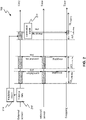
- FIG. 2 shows a schematic diagram 200 of how external sensor data and internal sensor data is used to select a cropping area
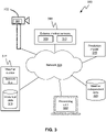
- FIG. 3 shows a schematic block diagram 300 of a system in which the invention can be implemented, in accordance with one embodiment.
- the system 300 includes a camera 302, which captures video and for which it is desired to perform image stabilization.
- the camera 302 includes one or more internal motion sensors 304, such as a gyroscope and/or accelerometer, which measure internal motion of the camera.
- the system 300 further includes a set of external motion sensors 306, such as a wind sensor 308 and a ground vibration sensor 310, which measure motion external to the camera 302.
- these external motion sensors 306 are located in close proximity of the camera 302.
- the system 300 further includes a weather station 312.
- the physical location of the weather station 312 with respect to the camera 302 can vary.
- the weather station 312 includes sensors 314, for example, a wind sensor, to measure current conditions.
- the weather station 312 also has access to historical data 316.
- a prediction model 318 form part of the system 300.
- the prediction model 318 will be explained below in further detail, but essentially operates in conjunction with the historical data 316 to "forecast" how the camera 302 will move under certain conditions. Further, as will be described below, in some situations, there may be camera movements that are not weather dependent (e.g., trains passing by a platform with a camera 302 on a regular schedule). Such weather-independent data can also be part of the system 300.
- system 300 includes a processing unit 322, which performs the data processing as will be described below. All these system components communicate with each other over a network 324, which may be a wired network, a wireless network, or a combination thereof. The communication can use standard or proprietary communication protocols. It should also be noted that while only one system component of each kind is shown in FIG. 3 , for ease of illustration purposes, in a real life implementation, there may be several components. For example, there may be several weather stations 312 or external motion sensors 306 that provide data to a single camera 302, or even to a group of cameras 302. Thus, the system embodiment 300 shown in FIG. 3 should not be construed as to the number and types of system components.
- the process 100 starts by collecting first external motion data 202 and first internal motion data 204, step 102.
- the first external motion data 202 is collected from one or more external motion sensors during a first time interval, ⁇ t1 collecting , as shown in FIG. 2 .
- the external motion data 202 includes data representative of external factors, such as wind direction, wind speed, and ground vibration, which may all affect movement of the camera. It should be noted that this is not an exclusive list, and that there may be other factors too that can affect movement of the camera, for example, large hail, as described above.
- the sensors and associated methods that are used to collect the external motion data 202 can be selected from a variety of commercially available sensors that are well known to those having ordinary skill in the art.
- the internal motion data 204 is also collected during the first time interval.
- the internal motion data 204 is collected from one or more internal motion sensors in the camera, such as a camera gyroscope or accelerometer, which are common components in many cameras.
- the internal motion data 204 can also be derived by analyzing the movement of pixels and determining an image processing motion vector estimate, in which case there would not be any need for having internal motion sensors in the camera.
- the first time interval can vary greatly, from minutes to days, weeks, months or even years in order to obtain statistical data sets that can be employed when using the method of the various embodiments of the invention. It should also be noted that the first time interval may be followed by one or more additional first time intervals, as illustrated in FIG. 2 . For example, collecting vibration data from a train that passes by the camera installation is typically a very short and predictable situation, whereas collecting data on a day with gusty winds may require a longer period of data collection in order to obtain an average wind speed value.
- a correlation 206 is made between the first external motion data 202 and the first internal motion data 204, step 104. That is, a first external motion datum, taken at a particular point in time, is correlated with a first internal motion datum, taken at the same point in time. For example, a wind sensor reading and/or the ground vibration sensor reading obtained at one point in time in the first time interval is correlated with a gyro reading obtained at the same point of time in the first time interval. Thus, for the same point in time, there will be a mapping between the external motion sensor datum and the internal motion sensor datum.
- the correlation is not limited to a one-to-one correspondence of sensor readings. For example, at a given point in time there may be one readout from the gyro, but that readout could be correlated to both a wind direction and a wind speed occurring at the same point in time.
- different sensors may support different sampling frequencies. For example, an internal gyro in the camera can be sampled at several hundred times per second, while an external wind sensor may only allow sampling once per second.
- the main point is the same. That is, to create a correlation between how an external sensor reading maps to an internal sensor reading.
- DIS Digital Image Stabilization
- SAD Sum of Absolute Differences
- second external motion data 208 is obtained, step 106. Typically, this is done using the same techniques that were described above in conjunction with step 102 and during a second time interval, ⁇ t2 collecting , that is subsequent to the first time interval ⁇ t1 collecting .
- the second external motion data 208 is not collected by sensor at the specific site of the camera, but instead obtained through a different process.
- the second external motion data 208 can be obtained from an external station, such as an external weather station.
- the external motion data 210 may be mapped to a timetable, e.g. a train timetable. This may for example be the case when the camera is installed at a railway platform and it is desirable to map the train timetable to ground vibrations caused by a train arriving, departing, or simply passing by.
- a timetable e.g. a train timetable. This may for example be the case when the camera is installed at a railway platform and it is desirable to map the train timetable to ground vibrations caused by a train arriving, departing, or simply passing by.
- the process ends by stabilizing a series of images captured during a third time interval by selecting a cropping area based on the correlation and the second external motion data, step 108.
- each internal motion datum e.g., each gyro reading
- a specific cropping e.g., a specific cropping area
- the correlation model 214 By applying the correlation model 214 to the external motion data 208, it is possible to map the external motion data 208 directly to a suitable cropping area for images captured during a third time interval, ⁇ t cropping , as shown in FIG. 2 .
- the third time interval can be totally separate from, or partly overlapping with, the second time interval. Just like the first and second time intervals, respectively, the third time interval can range from minutes, to hours, days, or weeks.
- An advantage of using the same single cropping when performing image stabilization during the third time interval is that the pixel size of the cropped images will remain the same during the third time interval. Thereby, all the images captured and stabilized during the third time interval will have the same resolution.
- the cropping is not changed very frequently, as it affects the zooming of the camera and having a very "reactive" cropping would create a very "jerky" image stream for a user watching the video from the camera with a lot of unnecessary zooming in/out. Too frequent zooming may also have a negative impact on the functioning of certain image analytics applications. In many embodiments, it is preferable to change the zooming only 1-2 times per 24 hour period, although, of course a large variation is possible also here.
- the determined single cropping area is selected as large as possible within the field of view of the images of the sequence of images. That is, the cropping area for third time interval is maximized to fit a percentage of the captured images.
- the second external motion data includes one or more outliers, e.g., one or more data indicating very large movement or vibration, these outliers may be disregarded when determining the cropping area.
- images captured during this large movement or vibration of the camera may be stabilized with the determined cropping area, although it may not be an optimal cropping area for these particular images.
- the cropping area may still optimally stabilize 95% - 99% of the captured images during the third time interval, and still provide significant advantages compared to conventional EIS methods.
- an advantage of maximizing the cropping area is that the pixel density also is maximized. Thereby, the image resolution and image quality are also maximized.
- the collected external motion data 208 and the prediction model 318 can also be used to determine how much the camera is likely to move or vibrate at a future point in time. This information can then be used by the camera system to suggest whether roll should be activated, or whether the camera should only perform image stabilization based on pitch and jaw.
- the camera system may suggest the range of stabilization, i.e. the range of the field of view used as cropping area. Based on pieces of information, the camera system may suggest a suitable EIS mode. In some embodiments, further factors can also be taken into account when proposing an EIS mode. For example, there may be situations in which it the EIS mode could vary depending on the season (e.g., one EIS mode for a hot summer day vs. another EIS mode for a cold snowy day), the time of day (e.g. one EIS mode for the daytime when there is a lot of traffic and a different EIS mode for the night time when things are relatively quiet). As can be seen, there are many variations that can be implemented by persons having ordinary skill in the art and based on the particular situation at hand.
- the EIS mode could vary depending on the season (e.g., one EIS mode for a hot summer day vs. another EIS mode for a cold snowy day), the time of day (e.g. one EIS mode for the daytime
- the systems and methods disclosed herein can be implemented as software, firmware, hardware or a combination thereof.
- the division of tasks between functional units or components referred to in the above description does not necessarily correspond to the division into physical units; on the contrary, one physical component can perform multiple functionalities, and one task may be carried out by several physical components in collaboration.
- Certain components or all components may be implemented as software executed by a digital signal processor or microprocessor, or be implemented as hardware or as an application-specific integrated circuit.
- Such software may be distributed on computer readable media, which may comprise computer storage media (or non-transitory media) and communication media (or transitory media).
- computer storage media includes both volatile and nonvolatile, removable and non-removable media implemented in any method or technology for storage of information such as computer readable instructions, data structures, program modules or other data.
- Computer storage media includes, but is not limited to, RAM, ROM, EEPROM, flash memory or other memory technology, CD-ROM, digital versatile disks (DVD) or other optical disk storage, magnetic cassettes, magnetic tape, magnetic disk storage or other magnetic storage devices, or any other medium which can be used to store the desired information and which can be accessed by a computer.
- each block in the flowchart or block diagrams may represent a module, segment, or portion of instructions, which comprises one or more executable instructions for implementing the specified logical function(s).
- the functions noted in the blocks may occur out of the order noted in the figures. For example, two blocks shown in succession may, in fact, be executed substantially concurrently, or the blocks may sometimes be executed in the reverse order, depending upon the functionality involved.
Landscapes
- Engineering & Computer Science (AREA)
- Multimedia (AREA)
- Signal Processing (AREA)
- Physics & Mathematics (AREA)
- General Physics & Mathematics (AREA)
- Theoretical Computer Science (AREA)
- Computer Vision & Pattern Recognition (AREA)
- Studio Devices (AREA)
- Adjustment Of Camera Lenses (AREA)
- Television Receiver Circuits (AREA)
Priority Applications (6)
| Application Number | Priority Date | Filing Date | Title |
|---|---|---|---|
| EP20171714.7A EP3905659B1 (en) | 2020-04-28 | 2020-04-28 | Statistics-based electronics image stabilization |
| TW110107495A TWI767592B (zh) | 2020-04-28 | 2021-03-03 | 基於統計之電子影像穩定 |
| KR1020210032105A KR102415194B1 (ko) | 2020-04-28 | 2021-03-11 | 통계 기반 전자식 이미지 안정화 |
| US17/237,246 US11363201B2 (en) | 2020-04-28 | 2021-04-22 | Statistics-based electronic image stabilization |
| CN202110441758.9A CN113572950B (zh) | 2020-04-28 | 2021-04-23 | 在图像序列中选择裁剪区域的方法、系统及存储介质 |
| JP2021074926A JP7123215B2 (ja) | 2020-04-28 | 2021-04-27 | 統計ベースの電子画像安定化 |
Applications Claiming Priority (1)
| Application Number | Priority Date | Filing Date | Title |
|---|---|---|---|
| EP20171714.7A EP3905659B1 (en) | 2020-04-28 | 2020-04-28 | Statistics-based electronics image stabilization |
Publications (2)
| Publication Number | Publication Date |
|---|---|
| EP3905659A1 EP3905659A1 (en) | 2021-11-03 |
| EP3905659B1 true EP3905659B1 (en) | 2022-06-01 |
Family
ID=70470966
Family Applications (1)
| Application Number | Title | Priority Date | Filing Date |
|---|---|---|---|
| EP20171714.7A Active EP3905659B1 (en) | 2020-04-28 | 2020-04-28 | Statistics-based electronics image stabilization |
Country Status (6)
| Country | Link |
|---|---|
| US (1) | US11363201B2 (zh) |
| EP (1) | EP3905659B1 (zh) |
| JP (1) | JP7123215B2 (zh) |
| KR (1) | KR102415194B1 (zh) |
| CN (1) | CN113572950B (zh) |
| TW (1) | TWI767592B (zh) |
Families Citing this family (1)
| Publication number | Priority date | Publication date | Assignee | Title |
|---|---|---|---|---|
| WO2023250261A1 (en) * | 2022-06-21 | 2023-12-28 | Qualcomm Incorporated | Dynamic image capture device configuration for improved image stabilization |
Family Cites Families (15)
| Publication number | Priority date | Publication date | Assignee | Title |
|---|---|---|---|---|
| EP0358196B1 (en) * | 1988-09-09 | 1997-07-30 | Canon Kabushiki Kaisha | Automatic image stabilization device |
| US5581297A (en) | 1992-07-24 | 1996-12-03 | Intelligent Instruments Corporation | Low power video security monitoring system |
| US7630620B2 (en) * | 2007-07-24 | 2009-12-08 | Honeywell International Inc. | Apparatus and method for measuring an acceleration to determine a camera dome's required motor holding current |
| JP5388910B2 (ja) | 2010-03-10 | 2014-01-15 | パナソニック株式会社 | 画像揺れ補正装置および画像揺れ補正方法 |
| US8760513B2 (en) * | 2011-09-30 | 2014-06-24 | Siemens Industry, Inc. | Methods and system for stabilizing live video in the presence of long-term image drift |
| US9628711B2 (en) * | 2011-12-15 | 2017-04-18 | Apple Inc. | Motion sensor based virtual tripod method for video stabilization |
| US8743222B2 (en) * | 2012-02-14 | 2014-06-03 | Nokia Corporation | Method and apparatus for cropping and stabilization of video images |
| US9686471B2 (en) * | 2013-11-01 | 2017-06-20 | Light Labs Inc. | Methods and apparatus relating to image stabilization |
| JP6350549B2 (ja) | 2014-02-14 | 2018-07-04 | 日本電気株式会社 | 映像解析システム |
| EP3096512B1 (en) | 2015-05-18 | 2017-03-22 | Axis AB | Method and camera for producing an image stabilized video |
| US20170041545A1 (en) * | 2015-08-06 | 2017-02-09 | Invensense, Inc. | Systems and methods for stabilizing images |
| EP3306528B1 (en) * | 2016-10-04 | 2019-12-25 | Axis AB | Using image analysis algorithms for providing traning data to neural networks |
| EP3340103A1 (en) * | 2016-12-21 | 2018-06-27 | Axis AB | Method for identifying events in a motion video |
| US10491807B2 (en) | 2017-06-27 | 2019-11-26 | GM Global Technology Operations LLC | Method to use vehicle information and sensors for photography and video viewing recording |
| US20190335074A1 (en) | 2018-04-27 | 2019-10-31 | Cubic Corporation | Eliminating effects of environmental conditions of images captured by an omnidirectional camera |
-
2020
- 2020-04-28 EP EP20171714.7A patent/EP3905659B1/en active Active
-
2021
- 2021-03-03 TW TW110107495A patent/TWI767592B/zh active
- 2021-03-11 KR KR1020210032105A patent/KR102415194B1/ko active IP Right Grant
- 2021-04-22 US US17/237,246 patent/US11363201B2/en active Active
- 2021-04-23 CN CN202110441758.9A patent/CN113572950B/zh active Active
- 2021-04-27 JP JP2021074926A patent/JP7123215B2/ja active Active
Also Published As
| Publication number | Publication date |
|---|---|
| CN113572950A (zh) | 2021-10-29 |
| EP3905659A1 (en) | 2021-11-03 |
| CN113572950B (zh) | 2022-12-23 |
| KR102415194B1 (ko) | 2022-06-30 |
| US20210337123A1 (en) | 2021-10-28 |
| KR20210133133A (ko) | 2021-11-05 |
| TW202213973A (zh) | 2022-04-01 |
| JP2021185658A (ja) | 2021-12-09 |
| JP7123215B2 (ja) | 2022-08-22 |
| US11363201B2 (en) | 2022-06-14 |
| TWI767592B (zh) | 2022-06-11 |
Similar Documents
| Publication | Publication Date | Title |
|---|---|---|
| CN101374199B (zh) | 成像设备和成像方法 | |
| CN110636223B (zh) | 防抖处理方法和装置、电子设备、计算机可读存储介质 | |
| KR101879332B1 (ko) | 전천사진으로부터 운량을 계산하는 방법, 그 계산한 운량을 이용하여 태양광 발전량을 예측하는 방법 및 그 방법을 이용하는 구름 관측 장치 | |
| US8891625B2 (en) | Stabilization method for vibrating video frames | |
| CN108347563B (zh) | 视频处理方法和装置、电子设备、计算机可读存储介质 | |
| EP2608529A1 (en) | Camera and method for optimizing the exposure of an image frame in a sequence of image frames capturing a scene based on level of motion in the scene | |
| KR20150031766A (ko) | 영상 흔들림 보정을 이용한 영상 안정화 장치 및 방법 | |
| KR101353021B1 (ko) | 이미지 캡쳐 시스템 및 이미지 캡쳐 방법 | |
| US11363201B2 (en) | Statistics-based electronic image stabilization | |
| KR102170691B1 (ko) | 감시용 카메라, 감시용 기록 장치, 및 감시 시스템 | |
| CN110266950B (zh) | 陀螺仪处理方法和装置、电子设备、计算机可读存储介质 | |
| CN110351508B (zh) | 基于录像模式的防抖处理方法和装置、电子设备 | |
| CN103956055A (zh) | 一种车辆图像抓拍装置及其抓拍控制方法 | |
| CN118573989A (zh) | 具有水平摇摄和/或俯仰摇摄操作的自校准功能的安防摄像头 | |
| KR102492679B1 (ko) | 객체 분석에 기반한 자동 감시 영상 생성 방법 및 그 장치 및 방법 | |
| KR101984070B1 (ko) | 지능형 스테레오 영상 기반 시설물 진동 감시 방법 | |
| CN111862142A (zh) | 一种运动轨迹生成方法、装置、设备和介质 | |
| US11438514B1 (en) | Performing image collection adjustment within a body-mounted camera | |
| KR102667465B1 (ko) | 연동형 인공지능 기반 cctv 시스템 | |
| US12114076B2 (en) | Differential frame rate settings | |
| JP6284203B2 (ja) | 監視装置 | |
| KR100734847B1 (ko) | 느린 셔터 속도에서 선명한 영상 검출 장치 및 방법 | |
| KR102681697B1 (ko) | 외부광에 의한 영향 없이 선명한 영상 촬영이 가능한 영상감시장치 | |
| US20230139436A1 (en) | Systems and methods for enhanced performance of camera devices | |
| KR102216874B1 (ko) | 다중 데이터 수집시스템을 통한 데이터 수집방법 |
Legal Events
| Date | Code | Title | Description |
|---|---|---|---|
| PUAI | Public reference made under article 153(3) epc to a published international application that has entered the european phase |
Free format text: ORIGINAL CODE: 0009012 |
|
| STAA | Information on the status of an ep patent application or granted ep patent |
Free format text: STATUS: REQUEST FOR EXAMINATION WAS MADE |
|
| 17P | Request for examination filed |
Effective date: 20201204 |
|
| AK | Designated contracting states |
Kind code of ref document: A1 Designated state(s): AL AT BE BG CH CY CZ DE DK EE ES FI FR GB GR HR HU IE IS IT LI LT LU LV MC MK MT NL NO PL PT RO RS SE SI SK SM TR |
|
| B565 | Issuance of search results under rule 164(2) epc |
Effective date: 20201126 |
|
| GRAP | Despatch of communication of intention to grant a patent |
Free format text: ORIGINAL CODE: EPIDOSNIGR1 |
|
| STAA | Information on the status of an ep patent application or granted ep patent |
Free format text: STATUS: GRANT OF PATENT IS INTENDED |
|
| INTG | Intention to grant announced |
Effective date: 20220105 |
|
| GRAS | Grant fee paid |
Free format text: ORIGINAL CODE: EPIDOSNIGR3 |
|
| GRAA | (expected) grant |
Free format text: ORIGINAL CODE: 0009210 |
|
| STAA | Information on the status of an ep patent application or granted ep patent |
Free format text: STATUS: THE PATENT HAS BEEN GRANTED |
|
| AK | Designated contracting states |
Kind code of ref document: B1 Designated state(s): AL AT BE BG CH CY CZ DE DK EE ES FI FR GB GR HR HU IE IS IT LI LT LU LV MC MK MT NL NO PL PT RO RS SE SI SK SM TR |
|
| REG | Reference to a national code |
Ref country code: GB Ref legal event code: FG4D |
|
| REG | Reference to a national code |
Ref country code: AT Ref legal event code: REF Ref document number: 1496190 Country of ref document: AT Kind code of ref document: T Effective date: 20220615 Ref country code: CH Ref legal event code: EP |
|
| REG | Reference to a national code |
Ref country code: IE Ref legal event code: FG4D |
|
| REG | Reference to a national code |
Ref country code: DE Ref legal event code: R096 Ref document number: 602020003333 Country of ref document: DE |
|
| REG | Reference to a national code |
Ref country code: SE Ref legal event code: TRGR |
|
| REG | Reference to a national code |
Ref country code: LT Ref legal event code: MG9D |
|
| REG | Reference to a national code |
Ref country code: NL Ref legal event code: MP Effective date: 20220601 |
|
| PG25 | Lapsed in a contracting state [announced via postgrant information from national office to epo] |
Ref country code: NO Free format text: LAPSE BECAUSE OF FAILURE TO SUBMIT A TRANSLATION OF THE DESCRIPTION OR TO PAY THE FEE WITHIN THE PRESCRIBED TIME-LIMIT Effective date: 20220901 Ref country code: LT Free format text: LAPSE BECAUSE OF FAILURE TO SUBMIT A TRANSLATION OF THE DESCRIPTION OR TO PAY THE FEE WITHIN THE PRESCRIBED TIME-LIMIT Effective date: 20220601 Ref country code: HR Free format text: LAPSE BECAUSE OF FAILURE TO SUBMIT A TRANSLATION OF THE DESCRIPTION OR TO PAY THE FEE WITHIN THE PRESCRIBED TIME-LIMIT Effective date: 20220601 Ref country code: GR Free format text: LAPSE BECAUSE OF FAILURE TO SUBMIT A TRANSLATION OF THE DESCRIPTION OR TO PAY THE FEE WITHIN THE PRESCRIBED TIME-LIMIT Effective date: 20220902 Ref country code: FI Free format text: LAPSE BECAUSE OF FAILURE TO SUBMIT A TRANSLATION OF THE DESCRIPTION OR TO PAY THE FEE WITHIN THE PRESCRIBED TIME-LIMIT Effective date: 20220601 Ref country code: BG Free format text: LAPSE BECAUSE OF FAILURE TO SUBMIT A TRANSLATION OF THE DESCRIPTION OR TO PAY THE FEE WITHIN THE PRESCRIBED TIME-LIMIT Effective date: 20220901 |
|
| REG | Reference to a national code |
Ref country code: AT Ref legal event code: MK05 Ref document number: 1496190 Country of ref document: AT Kind code of ref document: T Effective date: 20220601 |
|
| REG | Reference to a national code |
Ref country code: DE Ref legal event code: R079 Ref document number: 602020003333 Country of ref document: DE Free format text: PREVIOUS MAIN CLASS: H04N0005232000 Ipc: H04N0023600000 |
|
| PG25 | Lapsed in a contracting state [announced via postgrant information from national office to epo] |
Ref country code: RS Free format text: LAPSE BECAUSE OF FAILURE TO SUBMIT A TRANSLATION OF THE DESCRIPTION OR TO PAY THE FEE WITHIN THE PRESCRIBED TIME-LIMIT Effective date: 20220601 Ref country code: PL Free format text: LAPSE BECAUSE OF FAILURE TO SUBMIT A TRANSLATION OF THE DESCRIPTION OR TO PAY THE FEE WITHIN THE PRESCRIBED TIME-LIMIT Effective date: 20220601 Ref country code: LV Free format text: LAPSE BECAUSE OF FAILURE TO SUBMIT A TRANSLATION OF THE DESCRIPTION OR TO PAY THE FEE WITHIN THE PRESCRIBED TIME-LIMIT Effective date: 20220601 |
|
| PG25 | Lapsed in a contracting state [announced via postgrant information from national office to epo] |
Ref country code: NL Free format text: LAPSE BECAUSE OF FAILURE TO SUBMIT A TRANSLATION OF THE DESCRIPTION OR TO PAY THE FEE WITHIN THE PRESCRIBED TIME-LIMIT Effective date: 20220601 |
|
| PG25 | Lapsed in a contracting state [announced via postgrant information from national office to epo] |
Ref country code: SM Free format text: LAPSE BECAUSE OF FAILURE TO SUBMIT A TRANSLATION OF THE DESCRIPTION OR TO PAY THE FEE WITHIN THE PRESCRIBED TIME-LIMIT Effective date: 20220601 Ref country code: SK Free format text: LAPSE BECAUSE OF FAILURE TO SUBMIT A TRANSLATION OF THE DESCRIPTION OR TO PAY THE FEE WITHIN THE PRESCRIBED TIME-LIMIT Effective date: 20220601 Ref country code: RO Free format text: LAPSE BECAUSE OF FAILURE TO SUBMIT A TRANSLATION OF THE DESCRIPTION OR TO PAY THE FEE WITHIN THE PRESCRIBED TIME-LIMIT Effective date: 20220601 Ref country code: PT Free format text: LAPSE BECAUSE OF FAILURE TO SUBMIT A TRANSLATION OF THE DESCRIPTION OR TO PAY THE FEE WITHIN THE PRESCRIBED TIME-LIMIT Effective date: 20221003 Ref country code: ES Free format text: LAPSE BECAUSE OF FAILURE TO SUBMIT A TRANSLATION OF THE DESCRIPTION OR TO PAY THE FEE WITHIN THE PRESCRIBED TIME-LIMIT Effective date: 20220601 Ref country code: EE Free format text: LAPSE BECAUSE OF FAILURE TO SUBMIT A TRANSLATION OF THE DESCRIPTION OR TO PAY THE FEE WITHIN THE PRESCRIBED TIME-LIMIT Effective date: 20220601 Ref country code: CZ Free format text: LAPSE BECAUSE OF FAILURE TO SUBMIT A TRANSLATION OF THE DESCRIPTION OR TO PAY THE FEE WITHIN THE PRESCRIBED TIME-LIMIT Effective date: 20220601 Ref country code: AT Free format text: LAPSE BECAUSE OF FAILURE TO SUBMIT A TRANSLATION OF THE DESCRIPTION OR TO PAY THE FEE WITHIN THE PRESCRIBED TIME-LIMIT Effective date: 20220601 |
|
| PG25 | Lapsed in a contracting state [announced via postgrant information from national office to epo] |
Ref country code: IS Free format text: LAPSE BECAUSE OF FAILURE TO SUBMIT A TRANSLATION OF THE DESCRIPTION OR TO PAY THE FEE WITHIN THE PRESCRIBED TIME-LIMIT Effective date: 20221001 |
|
| REG | Reference to a national code |
Ref country code: DE Ref legal event code: R097 Ref document number: 602020003333 Country of ref document: DE |
|
| PG25 | Lapsed in a contracting state [announced via postgrant information from national office to epo] |
Ref country code: AL Free format text: LAPSE BECAUSE OF FAILURE TO SUBMIT A TRANSLATION OF THE DESCRIPTION OR TO PAY THE FEE WITHIN THE PRESCRIBED TIME-LIMIT Effective date: 20220601 |
|
| PLBE | No opposition filed within time limit |
Free format text: ORIGINAL CODE: 0009261 |
|
| STAA | Information on the status of an ep patent application or granted ep patent |
Free format text: STATUS: NO OPPOSITION FILED WITHIN TIME LIMIT |
|
| PG25 | Lapsed in a contracting state [announced via postgrant information from national office to epo] |
Ref country code: DK Free format text: LAPSE BECAUSE OF FAILURE TO SUBMIT A TRANSLATION OF THE DESCRIPTION OR TO PAY THE FEE WITHIN THE PRESCRIBED TIME-LIMIT Effective date: 20220601 |
|
| 26N | No opposition filed |
Effective date: 20230302 |
|
| P01 | Opt-out of the competence of the unified patent court (upc) registered |
Effective date: 20230505 |
|
| REG | Reference to a national code |
Ref country code: CH Ref legal event code: PL |
|
| PG25 | Lapsed in a contracting state [announced via postgrant information from national office to epo] |
Ref country code: LU Free format text: LAPSE BECAUSE OF NON-PAYMENT OF DUE FEES Effective date: 20230428 |
|
| REG | Reference to a national code |
Ref country code: BE Ref legal event code: MM Effective date: 20230430 |
|
| PG25 | Lapsed in a contracting state [announced via postgrant information from national office to epo] |
Ref country code: MC Free format text: LAPSE BECAUSE OF FAILURE TO SUBMIT A TRANSLATION OF THE DESCRIPTION OR TO PAY THE FEE WITHIN THE PRESCRIBED TIME-LIMIT Effective date: 20220601 |
|
| PG25 | Lapsed in a contracting state [announced via postgrant information from national office to epo] |
Ref country code: MC Free format text: LAPSE BECAUSE OF FAILURE TO SUBMIT A TRANSLATION OF THE DESCRIPTION OR TO PAY THE FEE WITHIN THE PRESCRIBED TIME-LIMIT Effective date: 20220601 Ref country code: LI Free format text: LAPSE BECAUSE OF NON-PAYMENT OF DUE FEES Effective date: 20230430 Ref country code: IT Free format text: LAPSE BECAUSE OF FAILURE TO SUBMIT A TRANSLATION OF THE DESCRIPTION OR TO PAY THE FEE WITHIN THE PRESCRIBED TIME-LIMIT Effective date: 20220601 Ref country code: CH Free format text: LAPSE BECAUSE OF NON-PAYMENT OF DUE FEES Effective date: 20230430 |
|
| REG | Reference to a national code |
Ref country code: IE Ref legal event code: MM4A |
|
| PG25 | Lapsed in a contracting state [announced via postgrant information from national office to epo] |
Ref country code: BE Free format text: LAPSE BECAUSE OF NON-PAYMENT OF DUE FEES Effective date: 20230430 |
|
| PG25 | Lapsed in a contracting state [announced via postgrant information from national office to epo] |
Ref country code: IE Free format text: LAPSE BECAUSE OF NON-PAYMENT OF DUE FEES Effective date: 20230428 |
|
| PG25 | Lapsed in a contracting state [announced via postgrant information from national office to epo] |
Ref country code: IE Free format text: LAPSE BECAUSE OF NON-PAYMENT OF DUE FEES Effective date: 20230428 |
|
| PGFP | Annual fee paid to national office [announced via postgrant information from national office to epo] |
Ref country code: GB Payment date: 20240321 Year of fee payment: 5 |
|
| PGFP | Annual fee paid to national office [announced via postgrant information from national office to epo] |
Ref country code: SE Payment date: 20240320 Year of fee payment: 5 Ref country code: FR Payment date: 20240320 Year of fee payment: 5 |
|
| PGFP | Annual fee paid to national office [announced via postgrant information from national office to epo] |
Ref country code: DE Payment date: 20240320 Year of fee payment: 5 |