EP3904686B1 - Verdrängerpumpe - Google Patents
Verdrängerpumpe Download PDFInfo
- Publication number
- EP3904686B1 EP3904686B1 EP20171964.8A EP20171964A EP3904686B1 EP 3904686 B1 EP3904686 B1 EP 3904686B1 EP 20171964 A EP20171964 A EP 20171964A EP 3904686 B1 EP3904686 B1 EP 3904686B1
- Authority
- EP
- European Patent Office
- Prior art keywords
- stator housing
- eccentric piston
- coupling
- eccentric
- coupling part
- Prior art date
- Legal status (The legal status is an assumption and is not a legal conclusion. Google has not performed a legal analysis and makes no representation as to the accuracy of the status listed.)
- Active
Links
Images


Classifications
-
- F—MECHANICAL ENGINEERING; LIGHTING; HEATING; WEAPONS; BLASTING
- F04—POSITIVE - DISPLACEMENT MACHINES FOR LIQUIDS; PUMPS FOR LIQUIDS OR ELASTIC FLUIDS
- F04C—ROTARY-PISTON, OR OSCILLATING-PISTON, POSITIVE-DISPLACEMENT MACHINES FOR LIQUIDS; ROTARY-PISTON, OR OSCILLATING-PISTON, POSITIVE-DISPLACEMENT PUMPS
- F04C2/00—Rotary-piston machines or pumps
- F04C2/02—Rotary-piston machines or pumps of arcuate-engagement type, i.e. with circular translatory movement of co-operating members, each member having the same number of teeth or tooth-equivalents
-
- F—MECHANICAL ENGINEERING; LIGHTING; HEATING; WEAPONS; BLASTING
- F01—MACHINES OR ENGINES IN GENERAL; ENGINE PLANTS IN GENERAL; STEAM ENGINES
- F01C—ROTARY-PISTON OR OSCILLATING-PISTON MACHINES OR ENGINES
- F01C17/00—Arrangements for drive of co-operating members, e.g. for rotary piston and casing
- F01C17/06—Arrangements for drive of co-operating members, e.g. for rotary piston and casing using cranks, universal joints or similar elements
- F01C17/066—Arrangements for drive of co-operating members, e.g. for rotary piston and casing using cranks, universal joints or similar elements with an intermediate piece sliding along perpendicular axes, e.g. Oldham coupling
-
- F—MECHANICAL ENGINEERING; LIGHTING; HEATING; WEAPONS; BLASTING
- F04—POSITIVE - DISPLACEMENT MACHINES FOR LIQUIDS; PUMPS FOR LIQUIDS OR ELASTIC FLUIDS
- F04C—ROTARY-PISTON, OR OSCILLATING-PISTON, POSITIVE-DISPLACEMENT MACHINES FOR LIQUIDS; ROTARY-PISTON, OR OSCILLATING-PISTON, POSITIVE-DISPLACEMENT PUMPS
- F04C15/00—Component parts, details or accessories of machines, pumps or pumping installations, not provided for in groups F04C2/00 - F04C14/00
- F04C15/0057—Driving elements, brakes, couplings, transmission specially adapted for machines or pumps
- F04C15/0061—Means for transmitting movement from the prime mover to driven parts of the pump, e.g. clutches, couplings, transmissions
- F04C15/0065—Means for transmitting movement from the prime mover to driven parts of the pump, e.g. clutches, couplings, transmissions for eccentric movement
-
- F—MECHANICAL ENGINEERING; LIGHTING; HEATING; WEAPONS; BLASTING
- F04—POSITIVE - DISPLACEMENT MACHINES FOR LIQUIDS; PUMPS FOR LIQUIDS OR ELASTIC FLUIDS
- F04C—ROTARY-PISTON, OR OSCILLATING-PISTON, POSITIVE-DISPLACEMENT MACHINES FOR LIQUIDS; ROTARY-PISTON, OR OSCILLATING-PISTON, POSITIVE-DISPLACEMENT PUMPS
- F04C15/00—Component parts, details or accessories of machines, pumps or pumping installations, not provided for in groups F04C2/00 - F04C14/00
- F04C15/0057—Driving elements, brakes, couplings, transmission specially adapted for machines or pumps
- F04C15/0061—Means for transmitting movement from the prime mover to driven parts of the pump, e.g. clutches, couplings, transmissions
- F04C15/0073—Couplings between rotors and input or output shafts acting by interengaging or mating parts, i.e. positive coupling of rotor and shaft
-
- F—MECHANICAL ENGINEERING; LIGHTING; HEATING; WEAPONS; BLASTING
- F04—POSITIVE - DISPLACEMENT MACHINES FOR LIQUIDS; PUMPS FOR LIQUIDS OR ELASTIC FLUIDS
- F04C—ROTARY-PISTON, OR OSCILLATING-PISTON, POSITIVE-DISPLACEMENT MACHINES FOR LIQUIDS; ROTARY-PISTON, OR OSCILLATING-PISTON, POSITIVE-DISPLACEMENT PUMPS
- F04C2/00—Rotary-piston machines or pumps
- F04C2/02—Rotary-piston machines or pumps of arcuate-engagement type, i.e. with circular translatory movement of co-operating members, each member having the same number of teeth or tooth-equivalents
- F04C2/04—Rotary-piston machines or pumps of arcuate-engagement type, i.e. with circular translatory movement of co-operating members, each member having the same number of teeth or tooth-equivalents of internal axis type
- F04C2/045—Rotary-piston machines or pumps of arcuate-engagement type, i.e. with circular translatory movement of co-operating members, each member having the same number of teeth or tooth-equivalents of internal axis type having a C-shaped piston
Definitions
- the invention relates to a positive displacement pump.
- a displacement pump has a stator housing and an eccentric piston.
- the eccentric piston executes a circular path relative to the stator housing.
- the eccentric piston is secured against twisting relative to the stator housing via a twist lock.
- this anti-rotation device must not block the relative movement between the eccentric piston and the stator housing on the circular path.
- At least one pump chamber is formed between the stator housing and the eccentric piston. The volume of the pump chamber changes with the movement of the eccentric piston along the circular path, with which the delivery of the fluid can be brought about by the displacement pump.
- DE 697 14 935 T2 discloses a positive displacement pump of the type explained in the introduction, in which the anti-rotation device is designed as a two-part corrugated tube which supports the eccentric piston on the starter housing.
- the torsional rigidity of the corrugated pipe ensures that there is no relative torsion between the eccentric piston and the stator housing.
- the corrugated tube is designed to be flexible about a transverse axis and axially compressible, which allows the relative movement between the eccentric piston and the stator housing on the circular path.
- the pamphlet EP 0 360 754 A2 discloses a displacement pump with the features of the preamble of the independent claim, in which an anti-twist device in the form of a cross-plate clutch is used between the eccentric piston and the stator housing.
- the cross disk arranged between the eccentric piston and the stator housing has on both sides two drivers that are offset by 180 degrees and aligned with one another are designed as spherical, semi-cylindrical extensions.
- the carriers on both sides of the cross disk are offset by 90 degrees to each other.
- the drivers on one side are accommodated in corresponding grooves of the stator housing in a form-fitting manner in the circumferential direction and displaceably in the radial direction.
- the drivers arranged on the other side of the cross disk are accommodated in corresponding grooves of the eccentric piston, whereby a form fit in the circumferential direction and a radial degree of freedom are also provided here.
- GB 1 446 214 A also discloses a displacement pump with an anti-rotation device in the form of a cross-plate clutch.
- the cross disk has four radial slots offset by 90 degrees from one another.
- Drivers designed as pins engage in two slots arranged opposite one another and are held on the eccentric piston, while drivers also designed as pins engage in the other slots and are held by the stator housing.
- the different rigidities of the corrugated pipe on the one hand with regard to torsion and, on the other hand, with regard to bending, a radial and/or axial offset, can be brought about by the corrugated pipe selected. However, this is only possible to a limited extent.
- the anti-rotation device is designed as a driver coupling.
- the eccentric piston is secured with regard to rotation in relation to the stator housing via the contact of drivers of clutch parts of the driver clutch in the circumferential direction. There is thus a related security by a positive fit of the drivers in the circumferential direction. Thus, a very stiff securing against the relative torsion can take place.
- the rotational position of the eccentric piston relative to the stator housing can also be specified very precisely by the design of the driver of the clutch parts.
- the required relative movement between the eccentric piston and the stator housing on the circular path is made possible by a relative movement of the drivers, which can be a relative sliding movement, for example.
- this relative movement does not require elastic loading of an elastic element, as would be the case when using a corrugated tube as an anti-twist device.
- the driver clutch has three clutch parts.
- a first clutch part is formed by or (directly or indirectly) held on the stator housing.
- a second clutch part is formed by the eccentric piston or (directly or indirectly) held by it.
- a third coupling part is arranged between the first coupling part and the second coupling part.
- the third coupling part is mounted on the first coupling part or on the second coupling part such that it can pivot about a first transverse axis.
- the storage also ensures an axial displacement along the first transverse axis.
- the third coupling part is also slidably mounted in the direction of a second transverse axis on the other of the first coupling part and the second coupling part.
- first transverse axis and the second transverse axis are oriented orthogonally to one another.
- the relative movement between the stator housing and the eccentric piston (and thus between the first clutch part and the second clutch part) can be ensured on a circular path on the one hand by the mobility along the first transverse axis and on the other hand by the mobility in the direction of the second transverse axis.
- the ability to pivot about a first transverse axis also ensures, under certain circumstances, an adjustment of the inclination.
- the driver clutch can have an axial degree of freedom, which, when using the aforementioned clutch parts, can mean that the first clutch part can be displaced axially relative to the third clutch part.
- This axial degree of freedom can be ensured, for example, between the third coupling part and the other of the first and second coupling parts by simultaneously ensuring mobility in the direction of the second transverse axis and mobility in the direction of the axial degree of freedom.
- the third clutch part is a clutch disc.
- the clutch disc may have two radial slots which are circumferentially offset by 180 degrees from each other and are thus located on opposite sides of the clutch disc.
- the clutch disc also has two pivot bolts.
- the pivot bolts are offset by 180 degrees from one another in the circumferential direction and are thus arranged on opposite sides of the clutch disc.
- the pivot bolts are arranged coaxially with one another.
- the pivot bolts are offset by 90 degrees in the circumferential direction relative to the aforementioned slots.
- the slots on the one hand and the pivot bolts on the other hand are thus provided on the clutch disc in the manner of an X or a cross.
- the driver formed by the eccentric piston or held on it (directly or indirectly) is rotatably mounted about the longitudinal axis of the pivot pin.
- the additional sliding degree of freedom can then be ensured in a particularly simple manner by this driver is mounted displaceably relative to the pivot pin in the longitudinal direction of the pivot pin.
- the driver can have a bearing eye or a bearing bore, through which the pivot pin extends, whereby the degree of freedom of rotation and the degree of freedom of displacement can be provided in a simple but reliable manner.
- two drivers formed by the stator or (directly or indirectly) held on it are guided displaceably in the radial direction and/or in the axial direction in the slots.
- the delimitations of the slots thus form driver surfaces, on which corresponding driver surfaces of the drivers formed by the stator housing or held thereon come to rest.
- the displacement in the radial direction and/or in the axial direction can then be ensured by means of a relative sliding movement of the driver surfaces.
- a corrugated pipe or a torsion-resistant bellows is not (exclusively) used for the anti-twist device.
- bellows are also used in a positive displacement pump according to the invention, via which the stator housing and the eccentric piston are then additionally connected.
- a torsionally soft bellows which can then be used exclusively or primarily for the necessary sealing, but at the same time enables the necessary relative movements.
- the bellows can be made of any desired material.
- a bellows is preferably made of plastic. It is possible that the bellows is made of a polymer material, in particular a PTFE.
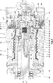
- a stator housing 5 is held on a housing 3, here a housing cover 4.
- the stator housing 5 has a basically hollow-cylindrical stator housing outer part 6 and a likewise hollow-cylindrical stator housing inner part 7 .
- the outer part 6 of the stator housing and the inner part 7 of the stator housing are designed and arranged concentrically to a drive axle 8 .
- the outer part 6 of the stator housing is firmly connected to the inner part 7 of the stator housing via a web 9 which runs approximately radially here.
- a receiving space 10 which is designed as a hollow cylinder and is oriented coaxially to the drive axis 4 .
- a connection duct 11 is formed in the outer part 6 of the stator housing adjacent to the web 9 in a circumferential direction, while the inner part 7 of the stator housing has a connection duct 32 on the side of the web 9 arranged in the other circumferential direction, and the inner part 7 of the stator housing here a slot or an opening 12 is formed.
- An eccentric piston 13 has an eccentric piston outer part 14 and an eccentric piston inner part 15, which have an annular body 33 (cf. 2 ) are firmly connected to each other.
- the eccentric piston outer part 14 is hollow-cylindrical and has a slot or an opening 16 through which the web 9 of the stator housing 5 extends.
- the eccentric piston inner part 15 has a cylindrical outer surface 17 and is also designed as a hollow cylinder for the exemplary embodiment shown.
- the outer part 14 of the eccentric piston and the lateral surface 17 of the inner part 15 of the eccentric piston are arranged concentrically to an eccentric axis 18 which has an eccentricity 19 in relation to the drive axis 8 .
- the eccentric axis 18 (and with this the eccentric piston 13) moves on a circular path 20 to the drive axis 8.
- the diameter of the effective cylindrical active surfaces of The stator housing 5 and the eccentric piston 13 are matched to one another in such a way that the lateral surface 17 of the eccentric piston inner part 15 forms a connecting gap 21 with an inner surface 22 of the stator housing inner part 7.
- a lateral surface 23 of the stator housing inner part 7 lies on the side opposite the eccentricity a sealing area 25 on an inner surface 24 of the stator housing outer part 6, while on the opposite side in the circumferential direction, i.e.
- a maximum gap is formed between the lateral surface 23 of the stator housing inner part 7 and the inner surface 24 of the eccentric piston outer part is with continuously changing gap height in between.
- a lateral surface 30 of the eccentric piston outer part 14 forms a sealing region 26 in the direction of the eccentricity with an inner surface 27 of the stator housing outer part 6, while these have a maximum spacing on the opposite side in the circumferential direction with a continuously changing distance between them in the circumferential direction .
- a pump chamber 28 is formed between the outer part of the stator housing 6 and the outer part of the eccentric piston 14, which is sealed in a peripheral end area by the sealing area 26.
- the sealing area 25 limited pump chamber 29 is one of the sealing area 25 limited pump chamber 29 formed.
- the sealing areas 25, 26 migrate accordingly in the direction of motion 31.
- the eccentric piston 13 on the circular path 20 there is no rotation of the eccentric piston 13 about a direction parallel to the drive axis 8 or Eccentric axis 18 oriented axis of rotation. Rather, the cross sections of the eccentric piston 13 during the movement on the circular path 20 in the in 1 shown cross-section the same orientation.
- the delivery effect of the displacement pump 1 is exemplified for a direction of movement 31 of the eccentric piston 13 on the circular path 20 in the clockwise direction 1 explained:
- the pump chamber 28 can be filled via the connection channel 11 with a fluid to be pumped. If the sealing area 26 is moved in front of the connection channel 11 in the direction of movement 31 , the sealing area 26 closes the connection between the connection channel 11 and the pump chamber 28 , while the pump chamber 28 is connected to a connection channel 32 .
- Sealing area 26 reduces the volume of the pump chamber 28 since the circumferential distance of the sealing area 26 from the connection channel 32 is reduced. The pump chamber 28 thus pushes the fluid arranged therein out of the connection channel 32 .
- the pump chamber 29 if its sealing area 25 is located behind the opening 16 in the direction of movement 31, the pump chamber 29 can also be filled with fluid from the connection channel 11. In the operating position according to 1 If the sealing area 25 has already shifted upwards, the pump chamber 29 arranged in front of the sealing area 25 in the direction of movement 31 has already reduced its volume to such an extent that fluid from the pump chamber 29 can also be pushed out of the connection channel 32.
- the pump chambers 28, 29 are arranged on opposite sides in the circumferential direction, so that they alternately suck in and push out fluid, whereby a delivery rate that is largely independent of the movement in the direction of movement 31 can be achieved. It is possible that the positive displacement pump 1 operates in a reversible manner, so that a reverse conveying effect can be achieved when the direction of movement 31 is reversed.
- a chamber formed between the inner surface 22 of the inner part 7 of the stator housing and the outer surface 17 of the inner part 15 of the eccentric piston is preferably not involved in the provision of the delivery capacity.
- stator housing 5 and the eccentric piston 13 and the pump chambers 28, 29 and their connection to the connection channels 11, 32 in 1 is merely an example - within the scope of the invention, other configurations known from the prior art can also be used for this purpose.
- stator housing 5 forms a half-longitudinal section corresponding to a horizontal U, with the side limbs of the horizontal U forming the outer part 6 of the stator housing and the inner part 7 of the stator housing, and the base limb U being formed by the annular body 33, which is divided into an axial Direction the pump chambers 28, 29 limited.
- the stator housing 5 is designed in one piece for the exemplary embodiment shown and is connected to the housing cover 4 and a hollow-cylindrical housing part 34 in order to form the housing 3. It is possible that pins 35 ensure an assembly aid, guidance and/or axial adjustability and/or attachment by means of housing screws 36 .
- the eccentric piston 13 is designed in several parts and has the eccentric piston outer part 14 and the eccentric piston inner part 15 and a union nut or cap 37, which are assembled together to form the eccentric piston 13 as a rigid structural unit.
- the eccentric piston outer part 14 is designed in the form of a lying T in half longitudinal section.
- the vertical leg of the lying T forms an annular body 38, the radially outer end area of which closes off the pump chamber 28 in the other axial direction and the radially inner end area of which is clamped between a shoulder of the eccentric piston inner part 15 and an end face of the cap 37, for which purpose the cap 37 with an internal thread can be screwed onto an external thread of an axial extension of the eccentric piston inner part 15 .
- An additional anti-twist device between the eccentric piston outer part 14 and the eccentric piston inner part 15 can be provided in that at least one pin 39 received in a longitudinal bore of the eccentric piston inner part 15 is positively received in the circumferential direction in a radial recess 40 in the inner surface of the annular body 38.
- the horizontal leg of the lying T forms the inner surface 24 on the inside and the lateral surface 30 on the outside.
- the eccentric piston 13 is driven to move on the circular path 20 via a pump shaft 41 rotating about the drive axis 8.
- the pump shaft 41 holds an eccentric shaft 43 in one end region in a manner that will be specified in more detail below, the eccentric axis 18 of which has the eccentricity 19 relative to the drive axis 8 is offset, so that the eccentric axis 18 moves with the rotation of the pump shaft 41 on the circular path 20.
- the eccentric shaft 43 forms a bearing journal 44, on which an inner ring 45 of a roller bearing 46 is mounted.
- An inner surface 48 of the eccentric piston 13 is supported on the outer ring 47 of the roller bearing 46 .
- the eccentric movement of the eccentric shaft 43 can be transmitted to the eccentric piston 13 via this support, the roller bearing 46 enabling the eccentric shaft 43 to rotate while the eccentric piston 13 does not perform any rotational movement.
- the inner part 15 of the eccentric piston forms a sleeve-shaped flange 49 .
- An end region of a bellows 50 is fastened to the flange 49 on the outside in a sealing manner.
- the other end area of the bellows 50 is also fastened with a seal to a bearing sleeve 51 which extends radially inwards from the housing part 34 coaxially with the drive axle 8 and is firmly connected to the housing part 34 in a manner not shown here.
- the bearing sleeve 51 serves to support roller bearings 52, 53 and sealing elements 54 lying radially on the inside.
- the roller bearings 52, 53 are used to support the pump shaft 41, while the sealing elements 54 are used to seal an interior of the housing 3 in which the roller bearings 52, 53 are arranged and lubricated.
- connection channel 32 is connected via the intermediate space between the housing part 34 and the bellows 50 to a fluidic connection 55 which, depending on the direction of movement 31 and thus the direction of rotation of the pump shaft 41, can be a suction side or a pressure side of the positive displacement pump 1.
- connection channel 11 is connected to a fluidic connection 56 which can then form the pressure side or the suction side of the displacement pump 1 .
- the pump chambers 28, 29 are sealed axially by the axial end faces of the stator housing 5 being pressed against associated end faces of the eccentric piston 13.
- the other spring foot point of the compression spring 57 is supported on the outer ring 47 of the roller bearing.
- the compressive force of the prestressed compression spring 57 acts on in 2 the eccentric piston 13 to the left in the direction of the stator housing 5, which is held firmly on the housing 3, whereby the required axial sealing of the pump chambers 28, 29 is ensured. If, as a result of the operation of the displacement pump 1, there is wear on the axial end faces pressed against one another, the eccentric piston 13 (caused by the compressive force of the compression spring 57) can carry out an adjustment movement ensuring further sealing with wear compensation.
- the eccentric shaft 43 is not held rigidly with the eccentricity 19 on the pump shaft 41 . Rather, the pump shaft 41 is connected via a pivot bearing 59 to pivot about a vertical to the eccentric axis 18 and / or to the drive axis 8 arranged pivot axis 60 with the eccentric shaft 43, wherein the eccentric shaft 43 of the Pivot bearing 59 extends out of the pump shaft 41 through a longitudinal recess 42 so that the bearing journal 44 formed by an end region of the eccentric shaft 43 is arranged outside of the pump shaft 41 .
- the pivot bearing 59 is provided with a bearing eye arranged in the inner end region of the eccentric shaft 43 and a bearing bolt penetrating the bearing eye, which is arranged in the base of the longitudinal recess 42 and passes through the pump shaft 41 in the direction of the pivot axis 60 and is held on the pump shaft 41 , educated.
- At least one sealing and/or adjusting spring 61a, 61b is arranged at a distance from the pivot axis 60 between the inner surface of the longitudinal recess 42 of the pump shaft 41 and the eccentric shaft 43.
- the sealing and/or readjusting spring 61a, 61b generates a loading torque on the eccentric shaft 43 about the pivot axis 60, which is directed in the direction of increasing the eccentricity 19.
- eccentric shaft 43 and the roller bearing 46 also the eccentric piston 13 are acted upon in the direction of the eccentricity via the sealing and/or adjustment spring 61a, 61b in such a way that a contact pressure ensuring the sealing effect is generated in the sealing areas 25, 26.
- the sealing and/or adjusting springs 61a, 61b can also increase the eccentricity 19 in the event of wear as a result of contact in the sealing areas 25, 26, with an associated adjusting movement, with which the desired sealing effect in the sealing area can continue to be achieved despite wear 25, 26 can be guaranteed.
- eccentric axis 18 may be inclined at a very small angle relative to drive axis 8. Such a small angle can be compensated for by roller bearing 46, which is designed as a self-aligning ball bearing for this purpose.
- the anti-rotation device 62 is designed as a driver coupling 63, which has three coupling parts 64, 65, 66 here.
- the coupling parts 64, 66 between which the coupling part 65 is arranged and with which the coupling part 65 in a manner to be explained in Interaction occurs, be formed as separate components or be formed integrally with the components already described.
- the coupling part 64 is held rigidly on the bearing sleeve 51, which is done by means of fastening screws 67 in the exemplary embodiment shown. However, it is also entirely possible for the coupling part 64 to be formed integrally with the bearing sleeve 51 .
- the coupling part 64 has an annular body 68 from which, in the direction of the drive axle 8, two drivers 69, 70 which are arranged on opposite sides in the circumferential direction protrude.
- the drivers 69, 70 are, for example, cuboidal or in the form of a hollow cylinder segment.
- the coupling part 65 is designed as a circular disk 71 and has slots 72, 73 oriented radially inward in the area of the lateral surface and formed by grooves.
- the lateral boundaries of the slots 72 form drivers 84a, 84b or 75a, 75b.
- the slots 72, 73 are arranged on opposite sides in the circumferential direction. In the slots 72, 73 of the coupling part 65, the drivers 69, 70 can be accommodated with a precise fit or form an accommodation with a clearance or transition fit.
- Driver contacts are formed between the drivers 69, 70 of the coupling part 64 and the drivers 74, 75 of the coupling part 65, which delimit the slots 72, 73 a sliding movement between the drivers, both a movement in the radial direction to the drive axis 8 or the eccentric axis 18, in the axial direction and also an inclination of the coupling part 65 relative to the coupling part 64 can allow.
- the circular disk 71 carries pivot bolts 76, 77 which are arranged coaxially with one another and protrude radially outwards from the circular disk 71.
- the pivot bolts 76, 77 can extend through slots 78, 79 formed by grooves in the circular disk 71, which can basically be formed corresponding to the slots 72, 73.
- the coupling part 66 is formed integrally with the flange 49 and has a driver 80 on opposite sides in the circumferential direction and a further driver that is hidden in the figures.
- the driver 80 and the hidden additional catches are in the longitudinal section 2 arranged at the level of the drive axle 8 or eccentric axle 18 in front of and behind the plane of the drawing.
- the driver 80 and the further driver each form, with an associated pivot bolt 76, 77, a pivot bearing for the bearing part 65, by means of which a relative pivoting of the coupling part 65 with respect to the coupling part 66 and thus with respect to the flange 49 about the axes defined by the longitudinal axes of the pivot bolts 76, 77 predetermined pivot axis is enabled.
- the accommodation of the pivot bolts 76, 77 in bearing eyes 81 formed by the drivers 80 also ensures a limited radial relative displacement of the coupling part 65 along the pivot axis specified by the pivot bolts 76, 77 relative to the flange 49.
- the pivot bolts 76, 77 also carriers 90, 91 of the coupling part 65, which, as a result of the inclusion in the bearing eyes 81 of the carriers 80 of the coupling part 66, allow a torque to be secured against rotation about the drive axis 8 or the eccentric axis 18 to be transmitted between the coupling parts 65, 66.
- the longitudinal axes of the pivot bolts 76, 77 define a first transverse axis 87.
- the coupling part 65 can be pivoted relative to the coupling part 66 about the transverse axis 87 .
- the coupling part 65 can be displaced along the transverse axis 87 relative to the coupling part 66 .
- the slots 72, 73 specify a second transverse axis 88 along which the coupling part 64 can be displaced relative to the coupling part 65.
- the engagement of the drivers 69, 70 of the coupling part 64 in the slots 72, 73 also ensures a relative axial degree of freedom 89.
- the eccentric piston 13 executes a movement along the circular path 20
- this is accompanied on the one hand by a radial compensating movement of the drivers 69, 70 in the slots 72, 73 along the second transverse axis 88 and of the pivot bolts 76, 77 in the bearing eyes 81 of the drivers 80 along the first transverse axis 87.
- the movement of the eccentric piston 13 on the circular path 20 is thus not impeded by the anti-twist device 62.
- the anti-rotation device 62 enables the transmission of the support torque or anti-rotation moment, which does not allow the eccentric piston 13 to rotate about the eccentric axis 18 or the drive axis 8 .
- positive displacement pump 1 can only the pump part 2 with the 2 and 3 described components have, while an example of an electric motor drive is not part of the positive displacement pump 1 and is therefore not the subject of the claim.
- the displacement pump 1 it is also entirely possible for the displacement pump 1 to have a drive part 82 with an electric drive in addition to the pump part 2, as is the case here 4 shows.
- the displacement pump 1 is supported by a flange 83 with respect to the environment.
- An output shaft 84 of the drive part 82 is non-rotatably connected to the pump shaft 41 via a coupling 85, which compensates for angular errors but transmits the drive torque , connected to the housing of the drive part 82.
- the anti-rotation device 62 is referred to as "driver coupling".
- ... coupling does not mean that the structural unit designated in this way connects two shafts rotating at the same or different speeds with one another. Rather, the “driver coupling” serves to (directly or indirectly) rotate the eccentric piston 13 to the stator housing 5 in a torque-proof manner, while ensuring the required and described degrees of freedom.
Landscapes
- Engineering & Computer Science (AREA)
- Mechanical Engineering (AREA)
- General Engineering & Computer Science (AREA)
- Reciprocating Pumps (AREA)
- Polysaccharides And Polysaccharide Derivatives (AREA)
Priority Applications (3)
| Application Number | Priority Date | Filing Date | Title |
|---|---|---|---|
| ES20171964T ES2943501T3 (es) | 2020-04-29 | 2020-04-29 | Bomba de desplazamiento positivo |
| PL20171964.8T PL3904686T3 (pl) | 2020-04-29 | 2020-04-29 | Pompa wyporowa |
| EP20171964.8A EP3904686B1 (de) | 2020-04-29 | 2020-04-29 | Verdrängerpumpe |
Applications Claiming Priority (1)
| Application Number | Priority Date | Filing Date | Title |
|---|---|---|---|
| EP20171964.8A EP3904686B1 (de) | 2020-04-29 | 2020-04-29 | Verdrängerpumpe |
Publications (2)
| Publication Number | Publication Date |
|---|---|
| EP3904686A1 EP3904686A1 (de) | 2021-11-03 |
| EP3904686B1 true EP3904686B1 (de) | 2023-02-01 |
Family
ID=70476101
Family Applications (1)
| Application Number | Title | Priority Date | Filing Date |
|---|---|---|---|
| EP20171964.8A Active EP3904686B1 (de) | 2020-04-29 | 2020-04-29 | Verdrängerpumpe |
Country Status (3)
| Country | Link |
|---|---|
| EP (1) | EP3904686B1 (pl) |
| ES (1) | ES2943501T3 (pl) |
| PL (1) | PL3904686T3 (pl) |
Family Cites Families (4)
| Publication number | Priority date | Publication date | Assignee | Title |
|---|---|---|---|---|
| IT1005170B (it) * | 1972-11-01 | 1976-08-20 | Kagi B | Dispositivo d azionamento per ottenere un movimento oscillatorio o rotatorio per azione di un fluido liquido o gassoso sotto pressione |
| EP0360754B1 (de) * | 1988-09-20 | 1993-01-13 | Gutag Innovations Ag | Kreuzscheibenkupplung |
| FR2746452B1 (fr) | 1996-03-22 | 1998-04-24 | Mouvex | Dispositif d'entrainement rotatif etanche a excentricite, notamment pour pompe volumetrique |
| JP2003336657A (ja) * | 2002-05-17 | 2003-11-28 | Sanden Corp | 軸継手およびスクロール圧縮機 |
-
2020
- 2020-04-29 EP EP20171964.8A patent/EP3904686B1/de active Active
- 2020-04-29 PL PL20171964.8T patent/PL3904686T3/pl unknown
- 2020-04-29 ES ES20171964T patent/ES2943501T3/es active Active
Also Published As
| Publication number | Publication date |
|---|---|
| EP3904686A1 (de) | 2021-11-03 |
| ES2943501T3 (es) | 2023-06-13 |
| PL3904686T3 (pl) | 2023-08-07 |
Similar Documents
| Publication | Publication Date | Title |
|---|---|---|
| WO2009024336A1 (de) | Axialkolbenmaschine in schrägscheibenbauweise mit einer stellvorrichtung | |
| EP0422338B1 (de) | Hydraulischer Schwingungsdämpfer | |
| DE102016202532A1 (de) | Kugelgelenk | |
| EP2060824B1 (de) | Torsionsschwingungsdämpferanordnung | |
| DE102006004760A1 (de) | Hydraulischer Nockenwellenversteller | |
| EP1588052B1 (de) | Axialkolbenmaschine mit fixierbarem gleitstein an der schrägscheibe | |
| EP3904686B1 (de) | Verdrängerpumpe | |
| DE102005041579B4 (de) | Innenzahnradpumpe mit Füllstück | |
| EP3277977B1 (de) | Axialdämpfer | |
| EP2467592B1 (de) | Kraftstoffhochdruckpumpe | |
| DE3600884A1 (de) | Hochleistungs-drehdurchfuehrung | |
| EP3106698A1 (de) | Mechanisches getriebe mit integrierter lastmomentsperre | |
| DE102023101994A1 (de) | Stellvorrichtung | |
| DE102019200943B4 (de) | Elektromechanischer Linearantrieb | |
| DE60110314T2 (de) | Axialkolbenpumpe | |
| DE102007025652B4 (de) | Torsionsschwingungsdämpferanordnung | |
| WO2007138093A1 (de) | Verstellbare verdrängerpumpe | |
| DE102004032082B4 (de) | Betätigungseinrichtung für eine Kupplung | |
| DE102012107158B4 (de) | Mechanische Gleitringdichtung | |
| EP1369611A1 (de) | Ausrücker mit einer Einrichtung zum Ausgleich von Ungenauigkeiten in einer Reibungskupplung eines Kraftfahrzeugs | |
| DE102006044294B3 (de) | Radialkolbenpumpe | |
| DE102005033104B4 (de) | Verstellbares hydrostatisches Axialkolbentriebwerk mit zueinander phasenverschiebbaren Verdrängungsbewegungen der Verdrängerkörper | |
| WO2005064200A1 (de) | Mechanische spannvorrichtung für zugmittel mit gerichteter reibdämpfung | |
| DE10109770A1 (de) | Füllstücklose Innenzahnradpumpe | |
| WO2013001029A1 (de) | Drehdurchführung |
Legal Events
| Date | Code | Title | Description |
|---|---|---|---|
| PUAI | Public reference made under article 153(3) epc to a published international application that has entered the european phase |
Free format text: ORIGINAL CODE: 0009012 |
|
| STAA | Information on the status of an ep patent application or granted ep patent |
Free format text: STATUS: REQUEST FOR EXAMINATION WAS MADE |
|
| 17P | Request for examination filed |
Effective date: 20201217 |
|
| AK | Designated contracting states |
Kind code of ref document: A1 Designated state(s): AL AT BE BG CH CY CZ DE DK EE ES FI FR GB GR HR HU IE IS IT LI LT LU LV MC MK MT NL NO PL PT RO RS SE SI SK SM TR |
|
| B565 | Issuance of search results under rule 164(2) epc |
Effective date: 20200928 |
|
| GRAP | Despatch of communication of intention to grant a patent |
Free format text: ORIGINAL CODE: EPIDOSNIGR1 |
|
| STAA | Information on the status of an ep patent application or granted ep patent |
Free format text: STATUS: GRANT OF PATENT IS INTENDED |
|
| INTG | Intention to grant announced |
Effective date: 20220907 |
|
| GRAS | Grant fee paid |
Free format text: ORIGINAL CODE: EPIDOSNIGR3 |
|
| GRAA | (expected) grant |
Free format text: ORIGINAL CODE: 0009210 |
|
| STAA | Information on the status of an ep patent application or granted ep patent |
Free format text: STATUS: THE PATENT HAS BEEN GRANTED |
|
| AK | Designated contracting states |
Kind code of ref document: B1 Designated state(s): AL AT BE BG CH CY CZ DE DK EE ES FI FR GB GR HR HU IE IS IT LI LT LU LV MC MK MT NL NO PL PT RO RS SE SI SK SM TR |
|
| REG | Reference to a national code |
Ref country code: GB Ref legal event code: FG4D Free format text: NOT ENGLISH |
|
| REG | Reference to a national code |
Ref country code: CH Ref legal event code: EP Ref country code: AT Ref legal event code: REF Ref document number: 1547006 Country of ref document: AT Kind code of ref document: T Effective date: 20230215 |
|
| REG | Reference to a national code |
Ref country code: DE Ref legal event code: R096 Ref document number: 502020002469 Country of ref document: DE |
|
| REG | Reference to a national code |
Ref country code: IE Ref legal event code: FG4D Free format text: LANGUAGE OF EP DOCUMENT: GERMAN |
|
| REG | Reference to a national code |
Ref country code: LT Ref legal event code: MG9D |
|
| REG | Reference to a national code |
Ref country code: NL Ref legal event code: MP Effective date: 20230201 |
|
| REG | Reference to a national code |
Ref country code: ES Ref legal event code: FG2A Ref document number: 2943501 Country of ref document: ES Kind code of ref document: T3 Effective date: 20230613 |
|
| P01 | Opt-out of the competence of the unified patent court (upc) registered |
Effective date: 20230529 |
|
| PG25 | Lapsed in a contracting state [announced via postgrant information from national office to epo] |
Ref country code: RS Free format text: LAPSE BECAUSE OF FAILURE TO SUBMIT A TRANSLATION OF THE DESCRIPTION OR TO PAY THE FEE WITHIN THE PRESCRIBED TIME-LIMIT Effective date: 20230201 Ref country code: PT Free format text: LAPSE BECAUSE OF FAILURE TO SUBMIT A TRANSLATION OF THE DESCRIPTION OR TO PAY THE FEE WITHIN THE PRESCRIBED TIME-LIMIT Effective date: 20230601 Ref country code: NO Free format text: LAPSE BECAUSE OF FAILURE TO SUBMIT A TRANSLATION OF THE DESCRIPTION OR TO PAY THE FEE WITHIN THE PRESCRIBED TIME-LIMIT Effective date: 20230501 Ref country code: NL Free format text: LAPSE BECAUSE OF FAILURE TO SUBMIT A TRANSLATION OF THE DESCRIPTION OR TO PAY THE FEE WITHIN THE PRESCRIBED TIME-LIMIT Effective date: 20230201 Ref country code: LV Free format text: LAPSE BECAUSE OF FAILURE TO SUBMIT A TRANSLATION OF THE DESCRIPTION OR TO PAY THE FEE WITHIN THE PRESCRIBED TIME-LIMIT Effective date: 20230201 Ref country code: LT Free format text: LAPSE BECAUSE OF FAILURE TO SUBMIT A TRANSLATION OF THE DESCRIPTION OR TO PAY THE FEE WITHIN THE PRESCRIBED TIME-LIMIT Effective date: 20230201 Ref country code: HR Free format text: LAPSE BECAUSE OF FAILURE TO SUBMIT A TRANSLATION OF THE DESCRIPTION OR TO PAY THE FEE WITHIN THE PRESCRIBED TIME-LIMIT Effective date: 20230201 |
|
| PG25 | Lapsed in a contracting state [announced via postgrant information from national office to epo] |
Ref country code: SE Free format text: LAPSE BECAUSE OF FAILURE TO SUBMIT A TRANSLATION OF THE DESCRIPTION OR TO PAY THE FEE WITHIN THE PRESCRIBED TIME-LIMIT Effective date: 20230201 Ref country code: IS Free format text: LAPSE BECAUSE OF FAILURE TO SUBMIT A TRANSLATION OF THE DESCRIPTION OR TO PAY THE FEE WITHIN THE PRESCRIBED TIME-LIMIT Effective date: 20230601 Ref country code: GR Free format text: LAPSE BECAUSE OF FAILURE TO SUBMIT A TRANSLATION OF THE DESCRIPTION OR TO PAY THE FEE WITHIN THE PRESCRIBED TIME-LIMIT Effective date: 20230502 Ref country code: FI Free format text: LAPSE BECAUSE OF FAILURE TO SUBMIT A TRANSLATION OF THE DESCRIPTION OR TO PAY THE FEE WITHIN THE PRESCRIBED TIME-LIMIT Effective date: 20230201 |
|
| PG25 | Lapsed in a contracting state [announced via postgrant information from national office to epo] |
Ref country code: SM Free format text: LAPSE BECAUSE OF FAILURE TO SUBMIT A TRANSLATION OF THE DESCRIPTION OR TO PAY THE FEE WITHIN THE PRESCRIBED TIME-LIMIT Effective date: 20230201 Ref country code: RO Free format text: LAPSE BECAUSE OF FAILURE TO SUBMIT A TRANSLATION OF THE DESCRIPTION OR TO PAY THE FEE WITHIN THE PRESCRIBED TIME-LIMIT Effective date: 20230201 Ref country code: EE Free format text: LAPSE BECAUSE OF FAILURE TO SUBMIT A TRANSLATION OF THE DESCRIPTION OR TO PAY THE FEE WITHIN THE PRESCRIBED TIME-LIMIT Effective date: 20230201 Ref country code: DK Free format text: LAPSE BECAUSE OF FAILURE TO SUBMIT A TRANSLATION OF THE DESCRIPTION OR TO PAY THE FEE WITHIN THE PRESCRIBED TIME-LIMIT Effective date: 20230201 Ref country code: CZ Free format text: LAPSE BECAUSE OF FAILURE TO SUBMIT A TRANSLATION OF THE DESCRIPTION OR TO PAY THE FEE WITHIN THE PRESCRIBED TIME-LIMIT Effective date: 20230201 |
|
| REG | Reference to a national code |
Ref country code: DE Ref legal event code: R097 Ref document number: 502020002469 Country of ref document: DE |
|
| PG25 | Lapsed in a contracting state [announced via postgrant information from national office to epo] |
Ref country code: SK Free format text: LAPSE BECAUSE OF FAILURE TO SUBMIT A TRANSLATION OF THE DESCRIPTION OR TO PAY THE FEE WITHIN THE PRESCRIBED TIME-LIMIT Effective date: 20230201 |
|
| REG | Reference to a national code |
Ref country code: CH Ref legal event code: PL |
|
| PLBE | No opposition filed within time limit |
Free format text: ORIGINAL CODE: 0009261 |
|
| STAA | Information on the status of an ep patent application or granted ep patent |
Free format text: STATUS: NO OPPOSITION FILED WITHIN TIME LIMIT |
|
| PG25 | Lapsed in a contracting state [announced via postgrant information from national office to epo] |
Ref country code: LU Free format text: LAPSE BECAUSE OF NON-PAYMENT OF DUE FEES Effective date: 20230429 |
|
| 26N | No opposition filed |
Effective date: 20231103 |
|
| REG | Reference to a national code |
Ref country code: BE Ref legal event code: MM Effective date: 20230430 |
|
| PG25 | Lapsed in a contracting state [announced via postgrant information from national office to epo] |
Ref country code: MC Free format text: LAPSE BECAUSE OF FAILURE TO SUBMIT A TRANSLATION OF THE DESCRIPTION OR TO PAY THE FEE WITHIN THE PRESCRIBED TIME-LIMIT Effective date: 20230201 |
|
| PG25 | Lapsed in a contracting state [announced via postgrant information from national office to epo] |
Ref country code: SI Free format text: LAPSE BECAUSE OF FAILURE TO SUBMIT A TRANSLATION OF THE DESCRIPTION OR TO PAY THE FEE WITHIN THE PRESCRIBED TIME-LIMIT Effective date: 20230201 Ref country code: MC Free format text: LAPSE BECAUSE OF FAILURE TO SUBMIT A TRANSLATION OF THE DESCRIPTION OR TO PAY THE FEE WITHIN THE PRESCRIBED TIME-LIMIT Effective date: 20230201 Ref country code: LI Free format text: LAPSE BECAUSE OF NON-PAYMENT OF DUE FEES Effective date: 20230430 Ref country code: CH Free format text: LAPSE BECAUSE OF NON-PAYMENT OF DUE FEES Effective date: 20230430 |
|
| REG | Reference to a national code |
Ref country code: IE Ref legal event code: MM4A |
|
| PG25 | Lapsed in a contracting state [announced via postgrant information from national office to epo] |
Ref country code: BE Free format text: LAPSE BECAUSE OF NON-PAYMENT OF DUE FEES Effective date: 20230430 |
|
| PG25 | Lapsed in a contracting state [announced via postgrant information from national office to epo] |
Ref country code: IE Free format text: LAPSE BECAUSE OF NON-PAYMENT OF DUE FEES Effective date: 20230429 |
|
| PG25 | Lapsed in a contracting state [announced via postgrant information from national office to epo] |
Ref country code: IE Free format text: LAPSE BECAUSE OF NON-PAYMENT OF DUE FEES Effective date: 20230429 |
|
| PG25 | Lapsed in a contracting state [announced via postgrant information from national office to epo] |
Ref country code: BG Free format text: LAPSE BECAUSE OF FAILURE TO SUBMIT A TRANSLATION OF THE DESCRIPTION OR TO PAY THE FEE WITHIN THE PRESCRIBED TIME-LIMIT Effective date: 20230201 |
|
| PG25 | Lapsed in a contracting state [announced via postgrant information from national office to epo] |
Ref country code: BG Free format text: LAPSE BECAUSE OF FAILURE TO SUBMIT A TRANSLATION OF THE DESCRIPTION OR TO PAY THE FEE WITHIN THE PRESCRIBED TIME-LIMIT Effective date: 20230201 |
|
| GBPC | Gb: european patent ceased through non-payment of renewal fee |
Effective date: 20240429 |
|
| PG25 | Lapsed in a contracting state [announced via postgrant information from national office to epo] |
Ref country code: GB Free format text: LAPSE BECAUSE OF NON-PAYMENT OF DUE FEES Effective date: 20240429 |
|
| PG25 | Lapsed in a contracting state [announced via postgrant information from national office to epo] |
Ref country code: GB Free format text: LAPSE BECAUSE OF NON-PAYMENT OF DUE FEES Effective date: 20240429 |
|
| PGFP | Annual fee paid to national office [announced via postgrant information from national office to epo] |
Ref country code: PL Payment date: 20250417 Year of fee payment: 6 Ref country code: DE Payment date: 20250212 Year of fee payment: 6 |
|
| PGFP | Annual fee paid to national office [announced via postgrant information from national office to epo] |
Ref country code: ES Payment date: 20250519 Year of fee payment: 6 |
|
| PGFP | Annual fee paid to national office [announced via postgrant information from national office to epo] |
Ref country code: IT Payment date: 20250430 Year of fee payment: 6 |
|
| PGFP | Annual fee paid to national office [announced via postgrant information from national office to epo] |
Ref country code: FR Payment date: 20250425 Year of fee payment: 6 |
|
| PGFP | Annual fee paid to national office [announced via postgrant information from national office to epo] |
Ref country code: AT Payment date: 20250721 Year of fee payment: 5 |
|
| PG25 | Lapsed in a contracting state [announced via postgrant information from national office to epo] |
Ref country code: CY Free format text: LAPSE BECAUSE OF FAILURE TO SUBMIT A TRANSLATION OF THE DESCRIPTION OR TO PAY THE FEE WITHIN THE PRESCRIBED TIME-LIMIT; INVALID AB INITIO Effective date: 20200429 |
|
| PG25 | Lapsed in a contracting state [announced via postgrant information from national office to epo] |
Ref country code: HU Free format text: LAPSE BECAUSE OF FAILURE TO SUBMIT A TRANSLATION OF THE DESCRIPTION OR TO PAY THE FEE WITHIN THE PRESCRIBED TIME-LIMIT; INVALID AB INITIO Effective date: 20200429 |
|
| PG25 | Lapsed in a contracting state [announced via postgrant information from national office to epo] |
Ref country code: TR Free format text: LAPSE BECAUSE OF FAILURE TO SUBMIT A TRANSLATION OF THE DESCRIPTION OR TO PAY THE FEE WITHIN THE PRESCRIBED TIME-LIMIT Effective date: 20230201 |