EP3901729B1 - Leistungsoptimierungsverfahren und -einrichtung dafür, photovoltaische vorrichtung und photovoltaisches system - Google Patents
Leistungsoptimierungsverfahren und -einrichtung dafür, photovoltaische vorrichtung und photovoltaisches system Download PDFInfo
- Publication number
- EP3901729B1 EP3901729B1 EP19900048.0A EP19900048A EP3901729B1 EP 3901729 B1 EP3901729 B1 EP 3901729B1 EP 19900048 A EP19900048 A EP 19900048A EP 3901729 B1 EP3901729 B1 EP 3901729B1
- Authority
- EP
- European Patent Office
- Prior art keywords
- photovoltaic assembly
- photovoltaic
- power optimization
- constant voltage
- condition
- Prior art date
- Legal status (The legal status is an assumption and is not a legal conclusion. Google has not performed a legal analysis and makes no representation as to the accuracy of the status listed.)
- Active
Links
Images


Classifications
-
- G—PHYSICS
- G05—CONTROLLING; REGULATING
- G05F—SYSTEMS FOR REGULATING ELECTRIC OR MAGNETIC VARIABLES
- G05F1/00—Automatic systems in which deviations of an electric quantity from one or more predetermined values are detected at the output of the system and fed back to a device within the system to restore the detected quantity to its predetermined value or values, i.e. retroactive systems
- G05F1/66—Regulating electric power
- G05F1/67—Regulating electric power to the maximum power available from a generator, e.g. from solar cell
-
- H—ELECTRICITY
- H02—GENERATION; CONVERSION OR DISTRIBUTION OF ELECTRIC POWER
- H02J—ELECTRIC POWER NETWORKS; CIRCUIT ARRANGEMENTS OR SYSTEMS FOR SUPPLYING OR DISTRIBUTING ELECTRIC POWER; SYSTEMS FOR STORING ELECTRIC ENERGY
- H02J3/00—Circuit arrangements for AC mains or AC distribution networks
- H02J3/38—Arrangements for feeding a single network from two or more generators or sources in parallel; Arrangements for feeding already energised networks from additional generators or sources in parallel
- H02J3/381—Dispersed generators
-
- H—ELECTRICITY
- H02—GENERATION; CONVERSION OR DISTRIBUTION OF ELECTRIC POWER
- H02J—ELECTRIC POWER NETWORKS; CIRCUIT ARRANGEMENTS OR SYSTEMS FOR SUPPLYING OR DISTRIBUTING ELECTRIC POWER; SYSTEMS FOR STORING ELECTRIC ENERGY
- H02J3/00—Circuit arrangements for AC mains or AC distribution networks
- H02J3/38—Arrangements for feeding a single network from two or more generators or sources in parallel; Arrangements for feeding already energised networks from additional generators or sources in parallel
- H02J3/46—Controlling the sharing of generated power between the generators, sources or networks
-
- H—ELECTRICITY
- H02—GENERATION; CONVERSION OR DISTRIBUTION OF ELECTRIC POWER
- H02J—ELECTRIC POWER NETWORKS; CIRCUIT ARRANGEMENTS OR SYSTEMS FOR SUPPLYING OR DISTRIBUTING ELECTRIC POWER; SYSTEMS FOR STORING ELECTRIC ENERGY
- H02J2101/00—Supply or distribution of decentralised, dispersed or local electric power generation
- H02J2101/20—Dispersed power generation using renewable energy sources
- H02J2101/22—Solar energy
- H02J2101/24—Photovoltaics
- H02J2101/25—Photovoltaics involving maximum power point tracking control for photovoltaic sources
-
- Y—GENERAL TAGGING OF NEW TECHNOLOGICAL DEVELOPMENTS; GENERAL TAGGING OF CROSS-SECTIONAL TECHNOLOGIES SPANNING OVER SEVERAL SECTIONS OF THE IPC; TECHNICAL SUBJECTS COVERED BY FORMER USPC CROSS-REFERENCE ART COLLECTIONS [XRACs] AND DIGESTS
- Y02—TECHNOLOGIES OR APPLICATIONS FOR MITIGATION OR ADAPTATION AGAINST CLIMATE CHANGE
- Y02E—REDUCTION OF GREENHOUSE GAS [GHG] EMISSIONS, RELATED TO ENERGY GENERATION, TRANSMISSION OR DISTRIBUTION
- Y02E10/00—Energy generation through renewable energy sources
- Y02E10/50—Photovoltaic [PV] energy
- Y02E10/56—Power conversion systems, e.g. maximum power point trackers
Definitions
- the disclosure relates to the field of photovoltaic control, and in particular to a power optimization method and a power optimization apparatus, a photovoltaic device and a photovoltaic system.
- the photovoltaic power generation system is sensitive to the change of an external environment and the consistency of assemblies, and when the system encounters the mismatch problem caused by local shadow shielding or individual difference of photovoltaic assemblies, an output power of the system is remarkably reduced.
- the problem becomes one of important factors restricting the further popularization and application of the photovoltaic power generation.
- a photovoltaic group string is formed among individual assemblies in a series connection mode and then is connected to a photovoltaic DC (Direct Current), an inverter or an energy storage inverter system according to different requirements of the photovoltaic power and bus voltage.
- a photovoltaic DC Direct Current
- an inverter or an energy storage inverter system according to different requirements of the photovoltaic power and bus voltage.
- an MPPT Maximum Power Point Tracking
- MPPT Maximum Power Point Tracking
- the apparatus further comprising a first detecting module configured to detect a connection architecture of the photovoltaic assembly; and the optimization processing module configured to perform the MPPT processing on the photovoltaic assembly under a condition that the photovoltaic assembly adopts a series architecture.
- the apparatus further comprising a second detecting module configured to detect whether the photovoltaic assembly has a constant voltage output requirement under a condition that the photovoltaic assembly adopts a parallel architecture; and the control module further configured to enter a constant voltage output mode to output a constant voltage to the bus under a condition that the photovoltaic assembly has a constant voltage output requirement, and is further configured to perform the MPPT processing on the photovoltaic assembly under a condition that the photovoltaic assembly does not have a constant voltage output requirement.
- a second detecting module configured to detect whether the photovoltaic assembly has a constant voltage output requirement under a condition that the photovoltaic assembly adopts a parallel architecture
- the control module further configured to enter a constant voltage output mode to output a constant voltage to the bus under a condition that the photovoltaic assembly has a constant voltage output requirement, and is further configured to perform the MPPT processing on the photovoltaic assembly under a condition that the photovoltaic assembly does not have a constant voltage output requirement.
- the control module is further configured to detect whether the operating parameter of the photovoltaic assembly is less than a parameter threshold, and enter a constant voltage protection mode to control the photovoltaic assembly to output a constant voltage under a condition that the operating parameter of the photovoltaic assembly is less than a parameter threshold, detect whether the operating parameter of the photovoltaic assembly is still less than the parameter threshold after a preset time after entering the constant voltage protection mode, and exit the constant voltage protection mode to perform the MPPT processing on the photovoltaic assembly under a condition that the operating parameter of the photovoltaic assembly is not less than the parameter threshold, and is further configured to control the photovoltaic assembly to be shut down under a condition that the operating parameter of the photovoltaic assembly is still less than the parameter threshold.
- a power optimization apparatus comprising: a processor; and a memory coupled to the processor, storing program instructions which, when executed by the processor, cause the processor to implement the method according to any one of the embodiments described above.
- a photovoltaic device comprising: the power optimization apparatus according to any one of the embodiments described above, and a photovoltaic assembly in one-to-one correspondence with the power optimization apparatus.
- a photovoltaic system comprising a plurality of photovoltaic devices according to any one of the embodiments described above, wherein the photovoltaic devices are in a series architecture or parallel architecture.
- a non-transitory computer readable storage medium wherein the computer readable storage medium stores computer instructions which, when executed by a processor, implement the method according to any one of the embodiments described above.
- any particular value should be construed as exemplary only and not as limiting. Thus, other examples of the exemplary embodiments may have different values.
- the main reason has two aspects: firstly, an output characteristic curve has multiple peak values, the existing MPPT algorithm is interfered by a plurality of extreme points, and it is impossible to find a real maximum power point; secondly, due to characteristic mismatch, operating currents of the maximum power point of all parts of the system are different, and a power generation potential is wasted even if the system works at the maximum power point of a system characteristic curve.
- the present disclosure provides a solution for ensuring that the photovoltaic assembly operates at maximum power generation capacity by optimizing the power state of the photovoltaic assembly.
- FIG. 1 is an exemplary flow diagram of a power optimization method according to one embodiment of the present disclosure.
- the power optimization method is performed by a power optimization apparatus, and the power optimization apparatus is in one-to-one correspondence with the photovoltaic assembly.
- step 101 a MPPT processing is performed on a photovoltaic assembly according to an operating parameter of the photovoltaic assembly in one-to-one correspondence with the power optimization apparatus.
- step 102 the photovoltaic assembly is controlled according to a result of the MPPT processing to optimize a power state of the photovoltaic assembly.
- connection architecture of the photovoltaic assembly is not limited by the method, and the power optimization of the photovoltaic assembly can be realized under a condition that the photovoltaic assembly adopts a series architecture or a parallel architecture.
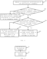
- Fig. 2 is an exemplary flow chart of a power optimization method of another embodiment of the present disclosure.
- the power optimization method may be performed by a power optimization apparatus, and the power optimization apparatus is in one-to-one correspondence with the photovoltaic assembly.
- step 201 a connection architecture of the photovoltaic assembly is detected.
- step 202 it is determined whether the photovoltaic assembly adopts a series architecture according to a detecting result.
- step 203 is executed.
- step 204 is executed.
- step 203 a power state of the photovoltaic assembly is optimized according to a MPPT mode of an assembly level.
- the embodiment shown in Fig. 1 may be employed to optimize the power state of the photovoltaic assembly.
- step 204 it is determined whether the photovoltaic assembly has a constant voltage output requirement.
- step 205 Under a condition that the photovoltaic assembly has a constant voltage output requirement, step 205 is executed. Under a condition that the photovoltaic assembly does not have the constant voltage output requirement, step 206 is executed.
- step 205 a constant voltage output mode is entered to output a constant voltage to the bus.
- the photovoltaic assembly has a constant voltage output requirement
- a constant voltage requirement at a preset voltage (e.g., 48V). If there is a 48V constant voltage requirement, then 48V output constant voltage mode is entered. If there isn't a 48V constant voltage requirement, a constant voltage mode for outputting the preset voltage is entered.
- a preset voltage e.g. 48V
- the power state of the photovoltaic assembly is optimized according to the MPPT mode of an assembly level.
- Fig. 1 may be employed to optimize the power state of the photovoltaic assembly.
- the MPPT algorithm is adopted to perform corresponding power optimization no matter the photovoltaic assembly adopts a series architecture or a parallel architecture.
- an operating parameter of the photovoltaic assembly is less than a parameter threshold. If the operating parameter of the photovoltaic assembly is less than the parameter threshold, it means that the output power of the photovoltaic assembly is obviously attenuated.
- a constant voltage protection mode is entered under this condition, and the photovoltaic assembly is controlled to output a constant voltage to protect the system.
- a preset time is delayed and the operating parameter of the photovoltaic assembly is detected whether still less than the parameter threshold. If the operating parameter of the photovoltaic assembly is not less than the parameter threshold, it means that the photovoltaic device does not have a fault, possibly the collected operating parameter has a deviation.
- the constant voltage protection mode is exited to continuously perform MPPT processing on the photovoltaic assembly. If the operating parameter of the photovoltaic assembly is still less than the parameter threshold, it means that the photovoltaic device has a fault at the moment, therefore the photovoltaic assembly is controlled to be shut down.
- the operating parameter of the photovoltaic assembly includes a voltage value or a current value of the photovoltaic assembly. Accordingly, the parameter threshold is also a corresponding voltage value or current value.
- Fig. 3 is an exemplary block diagram of a power optimization apparatus of one further embodiment of the present disclosure. As shown in Fig. 3 , the power optimization apparatus includes an optimization processing module 31 and a control module 32.
- the optimization processing module 31 is configured to perform MPPT processing on the photovoltaic assembly according to the operating parameter of the photovoltaic assembly in one-to-one correspondence with the power optimization apparatus.
- the control module 32 is configured to control the photovoltaic assembly according to a result of the MPPT processing to optimize a power state of the photovoltaic assembly.
- the power optimization apparatus performs MPPT processing on the corresponding photovoltaic assembly, wherein one power optimization apparatus is provided for each photovoltaic assembly, so that a power mismatch can be effectively avoided.
- the connection architecture of the photovoltaic assembly is not limited by the method, and the power optimization of the photovoltaic assembly can be realized under a condition that the photovoltaic assembly adopts a series architecture or a parallel architecture.
- Fig. 4 is an exemplary block diagram of a power optimization apparatus of the embodiment of the present disclosure.
- Fig. 4 differs from Fig. 3 in that in the embodiment shown in Fig. 4 , the power optimization apparatus further comprises a first detecting module 33 and a second detecting module 34.
- the first detecting module 33 is configured to identify the connection architecture of the photovoltaic assembly.
- the optimization processing module 31 is configured to perform the MPPT processing on the photovoltaic assembly under a condition that the photovoltaic assembly adopts a series architecture.
- the second detecting module 34 is configured to further identify whether the photovoltaic assembly has a constant voltage output requirement under a condition that the photovoltaic assembly adopts a parallel architecture.
- the control module 32 is further configured to enter a constant voltage output mode to output a constant voltage to the bus under a condition that the photovoltaic assembly has a constant voltage output requirement.
- the optimization processing module 31 is further configured to perform MPPT processing on the photovoltaic assembly under a condition that the photovoltaic assembly does not have a constant voltage output requirement.
- the MPPT algorithm may be adopted to perform corresponding power optimization no matter the photovoltaic assembly adopts a series architecture or a parallel architecture,
- control module 32 is further configured to detect whether the operating parameter of the photovoltaic assembly is less than a parameter threshold, and to enter a constant voltage protection mode under a condition that the operating parameter of the photovoltaic assembly is less than the parameter threshold, so as to control the photovoltaic assembly to output a constant voltage.
- the operating parameter of the photovoltaic assembly is less than the parameter threshold, which indicates that the output power of the photovoltaic assembly has obvious power attenuation. Under this condition, a constant voltage protection mode is entered, and the photovoltaic assembly is controlled to output a constant voltage so as to protect the system.
- control module 32 is further configured to detect whether the operating parameter of the photovoltaic assembly is still less than a parameter threshold after a preset time after entering the constant voltage protection mode, and exit the constant voltage protection mode under a condition that the operating parameter of the photovoltaic assembly is not less than the parameter threshold, so as to perform the MPPT processing on the photovoltaic assembly.
- the control module 32 is further configured to control the photovoltaic assembly to be shut down under a condition that the operating parameter of the photovoltaic assembly is still less than the parameter threshold. If the operating parameter of the photovoltaic assembly is not less than the parameter threshold, it means that the photovoltaic device does not have a fault, possibly the collected operating parameter has a deviation.
- the constant voltage protection mode is exited to continuously perform MPPT processing on the photovoltaic assembly. If the operating parameter of the photovoltaic assembly is still less than the parameter threshold, it means that the photovoltaic device has a fault at the moment, therefore the photovoltaic assembly is controlled to be shut down.
- Fig. 5 is an exemplary block diagram of a power optimization apparatus of.
- the power optimization apparatus includes a memory 51 and a processor 52.
- the memory 51 is used for storing instructions, and the processor 52 is coupled to the memory 51.
- the processor 52 is configured to execute the method according to. In the embodiment of figures 1 and 2 based on the instructions stored in the memory.
- the power optimization apparatus further includes a communication interface 53 for information interaction with other devices.
- the power optimization apparatus also comprises a bus 54, and the processor 52, the communication interface 53 and the memory 51 are communicated with each other through the bus 54.
- the memory 51 may comprise high-speed RAM memory, and may also include non-volatile memory (non-volatile memory), such as at least one disk memory.
- the memory 51 may also be a memory array.
- the storage 51 may also be partitioned and the blocks may be combined into virtual volumes according to certain rules.
- processor 52 may be a central processing unit CPU, or may be an application specific integrated circuit ASIC, or one or more integrated circuits configured to implement embodiments of the present disclosure.
- the present disclosure also relates to a non-transitory computer-readable storage medium, wherein the computer-readable storage medium stores computer instructions, and the instructions, when executed by a processor, implement the method according to Figs. 1 and 2 .
- Fig. 6 is an exemplary block diagram of a photovoltaic device of. In the embodiment of the invention.
- the photovoltaic device includes a photovoltaic assembly 61 and a power optimizing apparatus 62.
- the power optimization apparatus 62 is the power optimization apparatus according to. In the embodiment of the invention shown in Fig. 3 to Fig. 5 .
- the power optimization device is configured for the photovoltaic assembly to optimize the power state of the photovoltaic assembly.
- the present disclosure also provides a photovoltaic system comprising a plurality of photovoltaic devices as shown in Fig. 6 .
- Each photovoltaic device adopts a series architecture or a parallel architecture.
- a plurality of photovoltaic devices included in a photovoltaic system adopts a series architecture, i.e., the photovoltaic devices are connected in series.
- a plurality of photovoltaic devices comprised in the photovoltaic system adopts a parallel architecture, i.e. the photovoltaic devices are connected in parallel.
- the plurality of photovoltaic devices included in the photovoltaic system are divided into two parts, with the photovoltaic devices in the first part being connected in series and the photovoltaic devices in the second part being connected in parallel, i.e., in a series plus parallel topology.
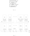
- Fig. 7 is an exemplary block diagram of a photovoltaic system of a further embodiment of the present disclosure.
- each photovoltaic assembly is provided with an optimizer, which is a power optimization device according to the embodiment of the invention in Fig. 3 to 5 .
- the series subsystem is formed by connecting the photovoltaic assemblies PV1, PV2, ... and PVn in series
- the parallel subsystem is formed by connecting the photovoltaic assemblies PVI, PVII, ... and PVm in parallel.
- the m + n photovoltaic assemblies shown in the Fig.7 form a photovoltaic assembly string system in a serial connection and parallel connection mode.
- the direct current buses on the output sides of the power optimizers installed at the photovoltaic assemblies can be independently supplied to direct current loads after being connected in parallel, and can also be connected to a photovoltaic DC device, an inverter or a direct current bus of an energy storage inverter system.
- the defects caused by mismatch of a conventional photovoltaic power generation system can be overcome according to actual requirements, the topological structure and the operating mode of the conventional photovoltaic power generation system can be expanded through the design mode of the free series-parallel component architecture. The functional expandability and the optimal perfection of the performance of the system can be ensured.
- the functional unit modules described above can be implemented as a general purpose Processor, a Programmable Logic Controller (PLC), a Digital Signal Processor (Digital Signal Processor, DSP), an Application Specific Integrated Circuit (ASIC), a Field Programmable Gate Array (FPGA) or other Programmable Logic device, discrete Gate or transistor Logic, discrete hardware components, or any suitable combination thereof for performing the functions described in this disclosure.
- PLC Programmable Logic Controller
- DSP Digital Signal Processor
- ASIC Application Specific Integrated Circuit
- FPGA Field Programmable Gate Array
- all or part of the steps for implementing the above embodiments may be implemented by hardware, or may be implemented by a program instructing relevant hardware, where the program may be stored in a computer-readable storage medium, and the storage medium may be a read-only memory, a magnetic disk or an optical disk.
Landscapes
- Engineering & Computer Science (AREA)
- Power Engineering (AREA)
- Electromagnetism (AREA)
- Sustainable Development (AREA)
- Sustainable Energy (AREA)
- Physics & Mathematics (AREA)
- Life Sciences & Earth Sciences (AREA)
- General Physics & Mathematics (AREA)
- Radar, Positioning & Navigation (AREA)
- Automation & Control Theory (AREA)
- Control Of Electrical Variables (AREA)
- Photovoltaic Devices (AREA)
- Supply And Distribution Of Alternating Current (AREA)
Claims (8)
- Leistungsoptimierungsverfahren, durchgeführt von einer Leistungsoptimierungsvorrichtung, das Verfahren umfassend:Erkennen einer Verbindungarchitektur einer photovoltaischen Anordnung (201);Durchführen einer Verarbeitung einer kontinuierlichen Leistungsmaximierung, MPPT (Maximum Power Point Tracking) an einer photovoltaischen Anordnung gemäß einem Betriebsparameter der photovoltaischen Anordnung unter der Bedingung, dass die photovoltaische Anordnung eine serielle Architektur (203) annimmt, wobei die photovoltaische Anordnung in eins-zu-eins-Entsprechung mit der Leistungsoptimierungsvorrichtung ist;Steuern der photovoltaischen Anordnung entsprechend einem Resultat der MPPT-Verarbeitung, um einen Leistungszustand der photovoltaischen Anordnung (102) zu optimieren;Erkennen, ob der Betriebsparameter der photovoltaischen Anordnung kleiner ist als ein Parameterschwellenwert, wobei der Betriebsparameter der photovoltaischen Anordnung einen Spannungswert oder einen Stromwert der photovoltaischen Anordnung umfasst;Wechseln in einen Konstantspannung-Schutzmodus, um die photovoltaische Anordnung zu steuern, um eine konstante Spannung auszugeben, wenn der Betriebsparameter der photovoltaischen Anordnung unter dem Parameterschwellenwert ist;Erkennen, ob der Betriebsparameter der photovoltaischen Anordnung nach einer vorgegebenen Zeit nach Wechseln in den Konstantspannung-Schutzmodus noch immer unter dem Parameterschwellenwert ist; undVerlassen des Konstantspannung-Schutzmodus, um die MPPT-Verarbeitung an der photovoltaischen Anordnung unter der Bedingung durchzuführen, dass der Betriebsparameter der photovoltaischen Anordnung nicht unter dem Parameterschwellenwert ist.
- Leistungsoptimierungsverfahren nach Anspruch 1, dadurch gekennzeichnet, dass es ferner Folgendes umfasst:Erkennen, ob die photovoltaische Anordnung eine Konstantspannung unter einer Bedingung ausgeben muss, dass die photovoltaische Anordnung eine parallele Architektur (204) annimmt; undWechseln in einen Konstantspannungs-Ausgabemodus zum Ausgeben einer konstanten Spannung an einen Bus unter der Bedingung, dass die photovoltaische Anordnung eine Konstantspannung-Ausgabeanforderung (205) hat.
- Leistungsoptimierungsverfahren nach Anspruch 2, dadurch gekennzeichnet, dass es ferner Folgendes umfasst:
Durchführen der MPPT-Verarbeitung an der photovoltaischen Anordnung unter der Bedingung, dass die photovoltaische Anordnung keine Konstantspannung ausgeben muss. - Leistungsoptimierungsverfahren nach einem der Ansprüche 1-3, dadurch gekennzeichnet, dass es ferner Folgendes umfasst:
Steuern der photovoltaischen Anordnung, um abzuschalten, unter der Bedingung, dass der Betriebsparameter der photovoltaischen Anordnung noch unter dem Parameterschwellenwert ist. - Leistungsoptimierungsvorrichtung, dadurch gekennzeichnet, dass sie Folgendes umfasst:einen Prozessor (52); undeinen mit dem Prozessor (52) gekoppelten Speicher (51), in dem Programmanweisungen gespeichert sind, die, wenn sie von dem Prozessor (52) ausgeführt werden, den Prozessor (52) veranlassen, das Verfahren nach einem der Ansprüche 1 bis 4 durchzuführen.
- Photovoltaische Vorrichtung, dadurch gekennzeichnet, dass sie Folgendes umfasst:die Leistungsoptimierungsvorrichtung (62) nach Anspruch 5, undeine photovoltaische Anordnung (61), in einer eins-zu-eins-Entsprechung mit der Leistungsoptimierungsvorrichtung (62).
- Photovoltaisches System, dadurch gekennzeichnet, dass es eine Vielzahl von photovoltaischen Vorrichtungen nach Anspruch 6 umfasst, wobei die photovoltaischen Vorrichtungen in einer seriellen Architektur oder parallelen Architektur sind.
- Nicht-transitorisches, computerlesbares Speichermedium, dadurch gekennzeichnet, dass das computerlesbare Speichermedium Computeranweisungen speichert, die, wenn sie von einem Prozessor ausgeführt werden, das Verfahren nach einem der Ansprüche 1-4 implementieren.
Applications Claiming Priority (2)
| Application Number | Priority Date | Filing Date | Title |
|---|---|---|---|
| CN201811548851.4A CN109634349B (zh) | 2018-12-18 | 2018-12-18 | 功率优化方法及其装置、光伏设备和光伏系统 |
| PCT/CN2019/092560 WO2020124973A1 (zh) | 2018-12-18 | 2019-06-24 | 功率优化方法及其装置、光伏设备和光伏系统 |
Publications (3)
| Publication Number | Publication Date |
|---|---|
| EP3901729A1 EP3901729A1 (de) | 2021-10-27 |
| EP3901729A4 EP3901729A4 (de) | 2022-06-08 |
| EP3901729B1 true EP3901729B1 (de) | 2024-08-07 |
Family
ID=66075034
Family Applications (1)
| Application Number | Title | Priority Date | Filing Date |
|---|---|---|---|
| EP19900048.0A Active EP3901729B1 (de) | 2018-12-18 | 2019-06-24 | Leistungsoptimierungsverfahren und -einrichtung dafür, photovoltaische vorrichtung und photovoltaisches system |
Country Status (6)
| Country | Link |
|---|---|
| US (1) | US11710969B2 (de) |
| EP (1) | EP3901729B1 (de) |
| CN (1) | CN109634349B (de) |
| AU (1) | AU2019401088B2 (de) |
| ES (1) | ES2993366T3 (de) |
| WO (1) | WO2020124973A1 (de) |
Families Citing this family (9)
| Publication number | Priority date | Publication date | Assignee | Title |
|---|---|---|---|---|
| CN109634349B (zh) | 2018-12-18 | 2020-06-30 | 珠海格力电器股份有限公司 | 功率优化方法及其装置、光伏设备和光伏系统 |
| CN110474418B (zh) * | 2019-08-26 | 2024-07-09 | 珠海格力电器股份有限公司 | 直流微电网系统及其运行控制方法和装置 |
| CN111708401B (zh) * | 2020-08-20 | 2020-11-20 | 浙江艾罗网络能源技术有限公司 | 一种适用于多种连接方式的光伏组件最大功率追踪方法 |
| CN112187168B (zh) * | 2020-09-27 | 2023-04-07 | 浙江工业大学 | 适合光伏组件串联系统的mppt控制器 |
| CN112925377B (zh) * | 2021-02-01 | 2022-07-29 | 浙江晶科能源有限公司 | 光伏系统及光伏系统的最大功率跟踪方法 |
| CN113517718B (zh) * | 2021-08-13 | 2024-06-25 | 阳光电源股份有限公司 | 一种光伏组串并联失配优化方法、电力设备和光伏系统 |
| CN115102170B (zh) * | 2022-08-25 | 2022-11-11 | 华能山西综合能源有限责任公司 | 一种风电光伏储能配比的协调优化方法 |
| CN117687467B (zh) * | 2023-11-29 | 2026-01-09 | 厦门科华数能科技有限公司 | 光伏组件的mppt扰动方法、装置、终端及存储介质 |
| CN118174361B (zh) * | 2024-05-14 | 2024-09-10 | 国网山东省电力公司日照供电公司 | 一种分布式光伏储能最大输出功率追踪方法及系统 |
Family Cites Families (9)
| Publication number | Priority date | Publication date | Assignee | Title |
|---|---|---|---|---|
| US7991511B2 (en) * | 2008-05-14 | 2011-08-02 | National Semiconductor Corporation | Method and system for selecting between centralized and distributed maximum power point tracking in an energy generating system |
| CN104426473B (zh) * | 2013-09-03 | 2018-06-15 | 深圳市金威源科技股份有限公司 | 一种太阳能光伏系统控制方法及控制装置 |
| CN104113280B (zh) * | 2014-07-05 | 2016-06-29 | 北京科诺伟业科技股份有限公司 | 串联式光伏方阵 |
| CN104092240B (zh) * | 2014-07-07 | 2016-08-24 | 阳光电源股份有限公司 | 一种光伏组件接入模式的识别方法及系统 |
| CN104579120A (zh) * | 2015-01-04 | 2015-04-29 | 国家电网公司 | 一种光伏发电离网运行时的控制方法 |
| CN106300612A (zh) * | 2016-08-26 | 2017-01-04 | 武汉理工大学 | 用于光伏直流供电系统中dc/dc的双模式控制系统及方法 |
| KR20180104873A (ko) | 2017-03-14 | 2018-09-27 | 주식회사 베가에너지 | 리튬 배터리 보호 시스템 |
| JP6887667B2 (ja) | 2017-03-28 | 2021-06-16 | 国立研究開発法人宇宙航空研究開発機構 | 電力制御システム |
| CN109634349B (zh) | 2018-12-18 | 2020-06-30 | 珠海格力电器股份有限公司 | 功率优化方法及其装置、光伏设备和光伏系统 |
-
2018
- 2018-12-18 CN CN201811548851.4A patent/CN109634349B/zh active Active
-
2019
- 2019-06-24 US US17/415,677 patent/US11710969B2/en active Active
- 2019-06-24 AU AU2019401088A patent/AU2019401088B2/en active Active
- 2019-06-24 ES ES19900048T patent/ES2993366T3/es active Active
- 2019-06-24 EP EP19900048.0A patent/EP3901729B1/de active Active
- 2019-06-24 WO PCT/CN2019/092560 patent/WO2020124973A1/zh not_active Ceased
Also Published As
| Publication number | Publication date |
|---|---|
| AU2019401088A1 (en) | 2021-07-01 |
| ES2993366T3 (en) | 2024-12-27 |
| EP3901729A4 (de) | 2022-06-08 |
| CN109634349A (zh) | 2019-04-16 |
| AU2019401088B2 (en) | 2025-02-20 |
| CN109634349B (zh) | 2020-06-30 |
| WO2020124973A1 (zh) | 2020-06-25 |
| EP3901729A1 (de) | 2021-10-27 |
| US20220190603A1 (en) | 2022-06-16 |
| US11710969B2 (en) | 2023-07-25 |
Similar Documents
| Publication | Publication Date | Title |
|---|---|---|
| EP3901729B1 (de) | Leistungsoptimierungsverfahren und -einrichtung dafür, photovoltaische vorrichtung und photovoltaisches system | |
| EP3264550B1 (de) | Zugangssteuerungsverfahren für parallele gleichstromquellen und vorrichtung dafür | |
| EP3324509A1 (de) | Stromversorgungssystem und stromversorgungsverfahren | |
| JP7582710B2 (ja) | 太陽光発電システム、並びに太陽光発電ストリングの地絡を検出する方法及び装置 | |
| EP3764504B1 (de) | Verfahren zur steuerung eines stringwechselrichters, regler, wechselrichter und wechselrichtersystem | |
| WO2017053724A1 (en) | Methods and systems for maintaining photovoltaic power plant reactive power capability | |
| Dhar et al. | Adaptive threshold based new active islanding protection scheme for multiple PV based microgrid application | |
| WO2020142890A1 (zh) | 母线电压的调节方法及相关设备 | |
| Wang et al. | Enhanced simulated annealing-based global MPPT for different PV systems in mismatched conditions | |
| CN110492592B (zh) | 直流微电网系统运行控制方法和装置 | |
| CN115453195B (zh) | 一种光伏逆变系统的绝缘阻抗检测方法及检测电路 | |
| CN111555283A (zh) | 一种不确定因素下配电网可用供电能力评估方法及系统 | |
| CN119834300B (zh) | 一种适用于全直流汇集构网型储能孤网启动控制方法及系统 | |
| CN114925993A (zh) | 一种含新能源电力系统连锁故障搜索方法及系统 | |
| CN118646063A (zh) | 多端柔性互联系统快速启动控制方法及相关装置 | |
| CN111313471A (zh) | 逆变器升压旁路切换方法及光伏发电系统 | |
| CN210092954U (zh) | 直流微电网系统 | |
| CN110474418B (zh) | 直流微电网系统及其运行控制方法和装置 | |
| CN117713249A (zh) | 具备灵活组网功能的微电网控制方法、装置和计算机设备 | |
| Shabani et al. | DC microgrid protection in the presence of the photovoltaic and energy storage systems | |
| Ji et al. | Fixed-Time Quasi-Consensus Current Sharing Control for Islanded DC Microgrids Under Unknown DoS Attacks Based on Event-Triggered Control | |
| Smith et al. | A review of design criteria for low voltage DC distribution stability | |
| CN115000971A (zh) | 集中式直流耗能系统及其控制方法和控制装置 | |
| CN105978483B (zh) | 光伏汇流箱及其防反二极管安装分析方法、装置 | |
| Lv et al. | Multi‐resolution modelling method based on time‐state‐machine in complex distribution network |
Legal Events
| Date | Code | Title | Description |
|---|---|---|---|
| STAA | Information on the status of an ep patent application or granted ep patent |
Free format text: STATUS: THE INTERNATIONAL PUBLICATION HAS BEEN MADE |
|
| PUAI | Public reference made under article 153(3) epc to a published international application that has entered the european phase |
Free format text: ORIGINAL CODE: 0009012 |
|
| STAA | Information on the status of an ep patent application or granted ep patent |
Free format text: STATUS: REQUEST FOR EXAMINATION WAS MADE |
|
| 17P | Request for examination filed |
Effective date: 20210618 |
|
| AK | Designated contracting states |
Kind code of ref document: A1 Designated state(s): AL AT BE BG CH CY CZ DE DK EE ES FI FR GB GR HR HU IE IS IT LI LT LU LV MC MK MT NL NO PL PT RO RS SE SI SK SM TR |
|
| DAV | Request for validation of the european patent (deleted) | ||
| DAX | Request for extension of the european patent (deleted) | ||
| A4 | Supplementary search report drawn up and despatched |
Effective date: 20220509 |
|
| RIC1 | Information provided on ipc code assigned before grant |
Ipc: G05F 1/67 20060101AFI20220502BHEP |
|
| P01 | Opt-out of the competence of the unified patent court (upc) registered |
Effective date: 20230530 |
|
| GRAP | Despatch of communication of intention to grant a patent |
Free format text: ORIGINAL CODE: EPIDOSNIGR1 |
|
| STAA | Information on the status of an ep patent application or granted ep patent |
Free format text: STATUS: GRANT OF PATENT IS INTENDED |
|
| INTG | Intention to grant announced |
Effective date: 20240306 |
|
| GRAS | Grant fee paid |
Free format text: ORIGINAL CODE: EPIDOSNIGR3 |
|
| GRAA | (expected) grant |
Free format text: ORIGINAL CODE: 0009210 |
|
| STAA | Information on the status of an ep patent application or granted ep patent |
Free format text: STATUS: THE PATENT HAS BEEN GRANTED |
|
| AK | Designated contracting states |
Kind code of ref document: B1 Designated state(s): AL AT BE BG CH CY CZ DE DK EE ES FI FR GB GR HR HU IE IS IT LI LT LU LV MC MK MT NL NO PL PT RO RS SE SI SK SM TR |
|
| REG | Reference to a national code |
Ref country code: GB Ref legal event code: FG4D |
|
| REG | Reference to a national code |
Ref country code: CH Ref legal event code: EP |
|
| REG | Reference to a national code |
Ref country code: IE Ref legal event code: FG4D |
|
| REG | Reference to a national code |
Ref country code: DE Ref legal event code: R096 Ref document number: 602019056789 Country of ref document: DE |
|
| REG | Reference to a national code |
Ref country code: LT Ref legal event code: MG9D |
|
| REG | Reference to a national code |
Ref country code: NL Ref legal event code: MP Effective date: 20240807 |
|
| REG | Reference to a national code |
Ref country code: ES Ref legal event code: FG2A Ref document number: 2993366 Country of ref document: ES Kind code of ref document: T3 Effective date: 20241227 |
|
| PG25 | Lapsed in a contracting state [announced via postgrant information from national office to epo] |
Ref country code: NO Free format text: LAPSE BECAUSE OF FAILURE TO SUBMIT A TRANSLATION OF THE DESCRIPTION OR TO PAY THE FEE WITHIN THE PRESCRIBED TIME-LIMIT Effective date: 20241107 |
|
| REG | Reference to a national code |
Ref country code: AT Ref legal event code: MK05 Ref document number: 1711651 Country of ref document: AT Kind code of ref document: T Effective date: 20240807 |
|
| PG25 | Lapsed in a contracting state [announced via postgrant information from national office to epo] |
Ref country code: NL Free format text: LAPSE BECAUSE OF FAILURE TO SUBMIT A TRANSLATION OF THE DESCRIPTION OR TO PAY THE FEE WITHIN THE PRESCRIBED TIME-LIMIT Effective date: 20240807 Ref country code: PT Free format text: LAPSE BECAUSE OF FAILURE TO SUBMIT A TRANSLATION OF THE DESCRIPTION OR TO PAY THE FEE WITHIN THE PRESCRIBED TIME-LIMIT Effective date: 20241209 Ref country code: GR Free format text: LAPSE BECAUSE OF FAILURE TO SUBMIT A TRANSLATION OF THE DESCRIPTION OR TO PAY THE FEE WITHIN THE PRESCRIBED TIME-LIMIT Effective date: 20241108 Ref country code: FI Free format text: LAPSE BECAUSE OF FAILURE TO SUBMIT A TRANSLATION OF THE DESCRIPTION OR TO PAY THE FEE WITHIN THE PRESCRIBED TIME-LIMIT Effective date: 20240807 Ref country code: PL Free format text: LAPSE BECAUSE OF FAILURE TO SUBMIT A TRANSLATION OF THE DESCRIPTION OR TO PAY THE FEE WITHIN THE PRESCRIBED TIME-LIMIT Effective date: 20240807 |
|
| PG25 | Lapsed in a contracting state [announced via postgrant information from national office to epo] |
Ref country code: BG Free format text: LAPSE BECAUSE OF FAILURE TO SUBMIT A TRANSLATION OF THE DESCRIPTION OR TO PAY THE FEE WITHIN THE PRESCRIBED TIME-LIMIT Effective date: 20240807 |
|
| PG25 | Lapsed in a contracting state [announced via postgrant information from national office to epo] |
Ref country code: LV Free format text: LAPSE BECAUSE OF FAILURE TO SUBMIT A TRANSLATION OF THE DESCRIPTION OR TO PAY THE FEE WITHIN THE PRESCRIBED TIME-LIMIT Effective date: 20240807 |
|
| PG25 | Lapsed in a contracting state [announced via postgrant information from national office to epo] |
Ref country code: AT Free format text: LAPSE BECAUSE OF FAILURE TO SUBMIT A TRANSLATION OF THE DESCRIPTION OR TO PAY THE FEE WITHIN THE PRESCRIBED TIME-LIMIT Effective date: 20240807 Ref country code: IS Free format text: LAPSE BECAUSE OF FAILURE TO SUBMIT A TRANSLATION OF THE DESCRIPTION OR TO PAY THE FEE WITHIN THE PRESCRIBED TIME-LIMIT Effective date: 20241207 |
|
| PG25 | Lapsed in a contracting state [announced via postgrant information from national office to epo] |
Ref country code: HR Free format text: LAPSE BECAUSE OF FAILURE TO SUBMIT A TRANSLATION OF THE DESCRIPTION OR TO PAY THE FEE WITHIN THE PRESCRIBED TIME-LIMIT Effective date: 20240807 |
|
| PG25 | Lapsed in a contracting state [announced via postgrant information from national office to epo] |
Ref country code: RS Free format text: LAPSE BECAUSE OF FAILURE TO SUBMIT A TRANSLATION OF THE DESCRIPTION OR TO PAY THE FEE WITHIN THE PRESCRIBED TIME-LIMIT Effective date: 20241107 |
|
| PG25 | Lapsed in a contracting state [announced via postgrant information from national office to epo] |
Ref country code: RS Free format text: LAPSE BECAUSE OF FAILURE TO SUBMIT A TRANSLATION OF THE DESCRIPTION OR TO PAY THE FEE WITHIN THE PRESCRIBED TIME-LIMIT Effective date: 20241107 Ref country code: PT Free format text: LAPSE BECAUSE OF FAILURE TO SUBMIT A TRANSLATION OF THE DESCRIPTION OR TO PAY THE FEE WITHIN THE PRESCRIBED TIME-LIMIT Effective date: 20241209 Ref country code: PL Free format text: LAPSE BECAUSE OF FAILURE TO SUBMIT A TRANSLATION OF THE DESCRIPTION OR TO PAY THE FEE WITHIN THE PRESCRIBED TIME-LIMIT Effective date: 20240807 Ref country code: NO Free format text: LAPSE BECAUSE OF FAILURE TO SUBMIT A TRANSLATION OF THE DESCRIPTION OR TO PAY THE FEE WITHIN THE PRESCRIBED TIME-LIMIT Effective date: 20241107 Ref country code: NL Free format text: LAPSE BECAUSE OF FAILURE TO SUBMIT A TRANSLATION OF THE DESCRIPTION OR TO PAY THE FEE WITHIN THE PRESCRIBED TIME-LIMIT Effective date: 20240807 Ref country code: LV Free format text: LAPSE BECAUSE OF FAILURE TO SUBMIT A TRANSLATION OF THE DESCRIPTION OR TO PAY THE FEE WITHIN THE PRESCRIBED TIME-LIMIT Effective date: 20240807 Ref country code: IS Free format text: LAPSE BECAUSE OF FAILURE TO SUBMIT A TRANSLATION OF THE DESCRIPTION OR TO PAY THE FEE WITHIN THE PRESCRIBED TIME-LIMIT Effective date: 20241207 Ref country code: HR Free format text: LAPSE BECAUSE OF FAILURE TO SUBMIT A TRANSLATION OF THE DESCRIPTION OR TO PAY THE FEE WITHIN THE PRESCRIBED TIME-LIMIT Effective date: 20240807 Ref country code: GR Free format text: LAPSE BECAUSE OF FAILURE TO SUBMIT A TRANSLATION OF THE DESCRIPTION OR TO PAY THE FEE WITHIN THE PRESCRIBED TIME-LIMIT Effective date: 20241108 Ref country code: FI Free format text: LAPSE BECAUSE OF FAILURE TO SUBMIT A TRANSLATION OF THE DESCRIPTION OR TO PAY THE FEE WITHIN THE PRESCRIBED TIME-LIMIT Effective date: 20240807 Ref country code: BG Free format text: LAPSE BECAUSE OF FAILURE TO SUBMIT A TRANSLATION OF THE DESCRIPTION OR TO PAY THE FEE WITHIN THE PRESCRIBED TIME-LIMIT Effective date: 20240807 Ref country code: AT Free format text: LAPSE BECAUSE OF FAILURE TO SUBMIT A TRANSLATION OF THE DESCRIPTION OR TO PAY THE FEE WITHIN THE PRESCRIBED TIME-LIMIT Effective date: 20240807 |
|
| PG25 | Lapsed in a contracting state [announced via postgrant information from national office to epo] |
Ref country code: RO Free format text: LAPSE BECAUSE OF FAILURE TO SUBMIT A TRANSLATION OF THE DESCRIPTION OR TO PAY THE FEE WITHIN THE PRESCRIBED TIME-LIMIT Effective date: 20240807 Ref country code: DK Free format text: LAPSE BECAUSE OF FAILURE TO SUBMIT A TRANSLATION OF THE DESCRIPTION OR TO PAY THE FEE WITHIN THE PRESCRIBED TIME-LIMIT Effective date: 20240807 Ref country code: SM Free format text: LAPSE BECAUSE OF FAILURE TO SUBMIT A TRANSLATION OF THE DESCRIPTION OR TO PAY THE FEE WITHIN THE PRESCRIBED TIME-LIMIT Effective date: 20240807 |
|
| PG25 | Lapsed in a contracting state [announced via postgrant information from national office to epo] |
Ref country code: EE Free format text: LAPSE BECAUSE OF FAILURE TO SUBMIT A TRANSLATION OF THE DESCRIPTION OR TO PAY THE FEE WITHIN THE PRESCRIBED TIME-LIMIT Effective date: 20240807 |
|
| PG25 | Lapsed in a contracting state [announced via postgrant information from national office to epo] |
Ref country code: CZ Free format text: LAPSE BECAUSE OF FAILURE TO SUBMIT A TRANSLATION OF THE DESCRIPTION OR TO PAY THE FEE WITHIN THE PRESCRIBED TIME-LIMIT Effective date: 20240807 |
|
| PG25 | Lapsed in a contracting state [announced via postgrant information from national office to epo] |
Ref country code: SK Free format text: LAPSE BECAUSE OF FAILURE TO SUBMIT A TRANSLATION OF THE DESCRIPTION OR TO PAY THE FEE WITHIN THE PRESCRIBED TIME-LIMIT Effective date: 20240807 |
|
| REG | Reference to a national code |
Ref country code: DE Ref legal event code: R097 Ref document number: 602019056789 Country of ref document: DE |
|
| PLBE | No opposition filed within time limit |
Free format text: ORIGINAL CODE: 0009261 |
|
| STAA | Information on the status of an ep patent application or granted ep patent |
Free format text: STATUS: NO OPPOSITION FILED WITHIN TIME LIMIT |
|
| PGFP | Annual fee paid to national office [announced via postgrant information from national office to epo] |
Ref country code: DE Payment date: 20250617 Year of fee payment: 7 |
|
| PGFP | Annual fee paid to national office [announced via postgrant information from national office to epo] |
Ref country code: GB Payment date: 20250625 Year of fee payment: 7 |
|
| 26N | No opposition filed |
Effective date: 20250508 |
|
| PGFP | Annual fee paid to national office [announced via postgrant information from national office to epo] |
Ref country code: FR Payment date: 20250527 Year of fee payment: 7 |
|
| PG25 | Lapsed in a contracting state [announced via postgrant information from national office to epo] |
Ref country code: SE Free format text: LAPSE BECAUSE OF FAILURE TO SUBMIT A TRANSLATION OF THE DESCRIPTION OR TO PAY THE FEE WITHIN THE PRESCRIBED TIME-LIMIT Effective date: 20240807 |
|
| PGFP | Annual fee paid to national office [announced via postgrant information from national office to epo] |
Ref country code: ES Payment date: 20250710 Year of fee payment: 7 |
|
| REG | Reference to a national code |
Ref country code: CH Ref legal event code: H13 Free format text: ST27 STATUS EVENT CODE: U-0-0-H10-H13 (AS PROVIDED BY THE NATIONAL OFFICE) Effective date: 20260127 |
|
| PG25 | Lapsed in a contracting state [announced via postgrant information from national office to epo] |
Ref country code: IT Free format text: LAPSE BECAUSE OF FAILURE TO SUBMIT A TRANSLATION OF THE DESCRIPTION OR TO PAY THE FEE WITHIN THE PRESCRIBED TIME-LIMIT Effective date: 20240807 |
|
| PG25 | Lapsed in a contracting state [announced via postgrant information from national office to epo] |
Ref country code: MC Free format text: LAPSE BECAUSE OF FAILURE TO SUBMIT A TRANSLATION OF THE DESCRIPTION OR TO PAY THE FEE WITHIN THE PRESCRIBED TIME-LIMIT Effective date: 20240807 |
|
| PG25 | Lapsed in a contracting state [announced via postgrant information from national office to epo] |
Ref country code: LU Free format text: LAPSE BECAUSE OF NON-PAYMENT OF DUE FEES Effective date: 20250624 |
|
| REG | Reference to a national code |
Ref country code: BE Ref legal event code: MM Effective date: 20250630 |
|
| PG25 | Lapsed in a contracting state [announced via postgrant information from national office to epo] |
Ref country code: IE Free format text: LAPSE BECAUSE OF NON-PAYMENT OF DUE FEES Effective date: 20250624 |
|
| PG25 | Lapsed in a contracting state [announced via postgrant information from national office to epo] |
Ref country code: BE Free format text: LAPSE BECAUSE OF NON-PAYMENT OF DUE FEES Effective date: 20250630 |
|
| PG25 | Lapsed in a contracting state [announced via postgrant information from national office to epo] |
Ref country code: CH Free format text: LAPSE BECAUSE OF NON-PAYMENT OF DUE FEES Effective date: 20250630 |