EP3901643A1 - Vorrichtung und verfahren zur bestimmung einer batteriezellenabnormalität - Google Patents
Vorrichtung und verfahren zur bestimmung einer batteriezellenabnormalität Download PDFInfo
- Publication number
- EP3901643A1 EP3901643A1 EP20756083.0A EP20756083A EP3901643A1 EP 3901643 A1 EP3901643 A1 EP 3901643A1 EP 20756083 A EP20756083 A EP 20756083A EP 3901643 A1 EP3901643 A1 EP 3901643A1
- Authority
- EP
- European Patent Office
- Prior art keywords
- battery cell
- capacity
- battery
- time
- magnetic field
- Prior art date
- Legal status (The legal status is an assumption and is not a legal conclusion. Google has not performed a legal analysis and makes no representation as to the accuracy of the status listed.)
- Pending
Links
- 230000005856 abnormality Effects 0.000 title claims abstract description 77
- 238000000034 method Methods 0.000 title claims description 23
- 238000005259 measurement Methods 0.000 claims abstract description 65
- 238000004519 manufacturing process Methods 0.000 claims description 73
- 230000006866 deterioration Effects 0.000 claims description 12
- 238000004146 energy storage Methods 0.000 claims description 5
- 238000004891 communication Methods 0.000 description 19
- 238000009529 body temperature measurement Methods 0.000 description 15
- 238000010586 diagram Methods 0.000 description 8
- 238000002474 experimental method Methods 0.000 description 8
- HBBGRARXTFLTSG-UHFFFAOYSA-N Lithium ion Chemical compound [Li+] HBBGRARXTFLTSG-UHFFFAOYSA-N 0.000 description 5
- 229910001416 lithium ion Inorganic materials 0.000 description 5
- PXHVJJICTQNCMI-UHFFFAOYSA-N nickel Substances [Ni] PXHVJJICTQNCMI-UHFFFAOYSA-N 0.000 description 4
- 239000004065 semiconductor Substances 0.000 description 4
- 229910000990 Ni alloy Inorganic materials 0.000 description 3
- 238000012986 modification Methods 0.000 description 3
- 230000004048 modification Effects 0.000 description 3
- 230000008901 benefit Effects 0.000 description 2
- 230000000694 effects Effects 0.000 description 2
- 230000014509 gene expression Effects 0.000 description 2
- 239000000758 substrate Substances 0.000 description 2
- 230000015556 catabolic process Effects 0.000 description 1
- 238000004590 computer program Methods 0.000 description 1
- 230000007850 degeneration Effects 0.000 description 1
- 238000006731 degradation reaction Methods 0.000 description 1
- 238000007599 discharging Methods 0.000 description 1
- 239000000463 material Substances 0.000 description 1
- 238000012827 research and development Methods 0.000 description 1
Images


Classifications
-
- G—PHYSICS
- G01—MEASURING; TESTING
- G01R—MEASURING ELECTRIC VARIABLES; MEASURING MAGNETIC VARIABLES
- G01R31/00—Arrangements for testing electric properties; Arrangements for locating electric faults; Arrangements for electrical testing characterised by what is being tested not provided for elsewhere
- G01R31/36—Arrangements for testing, measuring or monitoring the electrical condition of accumulators or electric batteries, e.g. capacity or state of charge [SoC]
- G01R31/396—Acquisition or processing of data for testing or for monitoring individual cells or groups of cells within a battery
-
- G—PHYSICS
- G01—MEASURING; TESTING
- G01R—MEASURING ELECTRIC VARIABLES; MEASURING MAGNETIC VARIABLES
- G01R19/00—Arrangements for measuring currents or voltages or for indicating presence or sign thereof
- G01R19/165—Indicating that current or voltage is either above or below a predetermined value or within or outside a predetermined range of values
- G01R19/16533—Indicating that current or voltage is either above or below a predetermined value or within or outside a predetermined range of values characterised by the application
- G01R19/16538—Indicating that current or voltage is either above or below a predetermined value or within or outside a predetermined range of values characterised by the application in AC or DC supplies
- G01R19/16542—Indicating that current or voltage is either above or below a predetermined value or within or outside a predetermined range of values characterised by the application in AC or DC supplies for batteries
-
- B—PERFORMING OPERATIONS; TRANSPORTING
- B60—VEHICLES IN GENERAL
- B60L—PROPULSION OF ELECTRICALLY-PROPELLED VEHICLES; SUPPLYING ELECTRIC POWER FOR AUXILIARY EQUIPMENT OF ELECTRICALLY-PROPELLED VEHICLES; ELECTRODYNAMIC BRAKE SYSTEMS FOR VEHICLES IN GENERAL; MAGNETIC SUSPENSION OR LEVITATION FOR VEHICLES; MONITORING OPERATING VARIABLES OF ELECTRICALLY-PROPELLED VEHICLES; ELECTRIC SAFETY DEVICES FOR ELECTRICALLY-PROPELLED VEHICLES
- B60L3/00—Electric devices on electrically-propelled vehicles for safety purposes; Monitoring operating variables, e.g. speed, deceleration or energy consumption
- B60L3/0023—Detecting, eliminating, remedying or compensating for drive train abnormalities, e.g. failures within the drive train
- B60L3/0046—Detecting, eliminating, remedying or compensating for drive train abnormalities, e.g. failures within the drive train relating to electric energy storage systems, e.g. batteries or capacitors
-
- B—PERFORMING OPERATIONS; TRANSPORTING
- B60—VEHICLES IN GENERAL
- B60L—PROPULSION OF ELECTRICALLY-PROPELLED VEHICLES; SUPPLYING ELECTRIC POWER FOR AUXILIARY EQUIPMENT OF ELECTRICALLY-PROPELLED VEHICLES; ELECTRODYNAMIC BRAKE SYSTEMS FOR VEHICLES IN GENERAL; MAGNETIC SUSPENSION OR LEVITATION FOR VEHICLES; MONITORING OPERATING VARIABLES OF ELECTRICALLY-PROPELLED VEHICLES; ELECTRIC SAFETY DEVICES FOR ELECTRICALLY-PROPELLED VEHICLES
- B60L58/00—Methods or circuit arrangements for monitoring or controlling batteries or fuel cells, specially adapted for electric vehicles
- B60L58/10—Methods or circuit arrangements for monitoring or controlling batteries or fuel cells, specially adapted for electric vehicles for monitoring or controlling batteries
- B60L58/12—Methods or circuit arrangements for monitoring or controlling batteries or fuel cells, specially adapted for electric vehicles for monitoring or controlling batteries responding to state of charge [SoC]
-
- B—PERFORMING OPERATIONS; TRANSPORTING
- B60—VEHICLES IN GENERAL
- B60L—PROPULSION OF ELECTRICALLY-PROPELLED VEHICLES; SUPPLYING ELECTRIC POWER FOR AUXILIARY EQUIPMENT OF ELECTRICALLY-PROPELLED VEHICLES; ELECTRODYNAMIC BRAKE SYSTEMS FOR VEHICLES IN GENERAL; MAGNETIC SUSPENSION OR LEVITATION FOR VEHICLES; MONITORING OPERATING VARIABLES OF ELECTRICALLY-PROPELLED VEHICLES; ELECTRIC SAFETY DEVICES FOR ELECTRICALLY-PROPELLED VEHICLES
- B60L58/00—Methods or circuit arrangements for monitoring or controlling batteries or fuel cells, specially adapted for electric vehicles
- B60L58/10—Methods or circuit arrangements for monitoring or controlling batteries or fuel cells, specially adapted for electric vehicles for monitoring or controlling batteries
- B60L58/16—Methods or circuit arrangements for monitoring or controlling batteries or fuel cells, specially adapted for electric vehicles for monitoring or controlling batteries responding to battery ageing, e.g. to the number of charging cycles or the state of health [SoH]
-
- G—PHYSICS
- G01—MEASURING; TESTING
- G01R—MEASURING ELECTRIC VARIABLES; MEASURING MAGNETIC VARIABLES
- G01R1/00—Details of instruments or arrangements of the types included in groups G01R5/00 - G01R13/00 and G01R31/00
- G01R1/02—General constructional details
- G01R1/18—Screening arrangements against electric or magnetic fields, e.g. against earth's field
-
- G—PHYSICS
- G01—MEASURING; TESTING
- G01R—MEASURING ELECTRIC VARIABLES; MEASURING MAGNETIC VARIABLES
- G01R15/00—Details of measuring arrangements of the types provided for in groups G01R17/00 - G01R29/00, G01R33/00 - G01R33/26 or G01R35/00
- G01R15/14—Adaptations providing voltage or current isolation, e.g. for high-voltage or high-current networks
- G01R15/20—Adaptations providing voltage or current isolation, e.g. for high-voltage or high-current networks using galvano-magnetic devices, e.g. Hall-effect devices, i.e. measuring a magnetic field via the interaction between a current and a magnetic field, e.g. magneto resistive or Hall effect devices
- G01R15/207—Constructional details independent of the type of device used
-
- G—PHYSICS
- G01—MEASURING; TESTING
- G01R—MEASURING ELECTRIC VARIABLES; MEASURING MAGNETIC VARIABLES
- G01R31/00—Arrangements for testing electric properties; Arrangements for locating electric faults; Arrangements for electrical testing characterised by what is being tested not provided for elsewhere
- G01R31/36—Arrangements for testing, measuring or monitoring the electrical condition of accumulators or electric batteries, e.g. capacity or state of charge [SoC]
- G01R31/382—Arrangements for monitoring battery or accumulator variables, e.g. SoC
- G01R31/3828—Arrangements for monitoring battery or accumulator variables, e.g. SoC using current integration
-
- G—PHYSICS
- G01—MEASURING; TESTING
- G01R—MEASURING ELECTRIC VARIABLES; MEASURING MAGNETIC VARIABLES
- G01R31/00—Arrangements for testing electric properties; Arrangements for locating electric faults; Arrangements for electrical testing characterised by what is being tested not provided for elsewhere
- G01R31/36—Arrangements for testing, measuring or monitoring the electrical condition of accumulators or electric batteries, e.g. capacity or state of charge [SoC]
- G01R31/382—Arrangements for monitoring battery or accumulator variables, e.g. SoC
- G01R31/3842—Arrangements for monitoring battery or accumulator variables, e.g. SoC combining voltage and current measurements
-
- G—PHYSICS
- G01—MEASURING; TESTING
- G01R—MEASURING ELECTRIC VARIABLES; MEASURING MAGNETIC VARIABLES
- G01R31/00—Arrangements for testing electric properties; Arrangements for locating electric faults; Arrangements for electrical testing characterised by what is being tested not provided for elsewhere
- G01R31/36—Arrangements for testing, measuring or monitoring the electrical condition of accumulators or electric batteries, e.g. capacity or state of charge [SoC]
- G01R31/385—Arrangements for measuring battery or accumulator variables
- G01R31/387—Determining ampere-hour charge capacity or SoC
-
- G—PHYSICS
- G01—MEASURING; TESTING
- G01R—MEASURING ELECTRIC VARIABLES; MEASURING MAGNETIC VARIABLES
- G01R31/00—Arrangements for testing electric properties; Arrangements for locating electric faults; Arrangements for electrical testing characterised by what is being tested not provided for elsewhere
- G01R31/36—Arrangements for testing, measuring or monitoring the electrical condition of accumulators or electric batteries, e.g. capacity or state of charge [SoC]
- G01R31/389—Measuring internal impedance, internal conductance or related variables
-
- G—PHYSICS
- G01—MEASURING; TESTING
- G01R—MEASURING ELECTRIC VARIABLES; MEASURING MAGNETIC VARIABLES
- G01R31/00—Arrangements for testing electric properties; Arrangements for locating electric faults; Arrangements for electrical testing characterised by what is being tested not provided for elsewhere
- G01R31/36—Arrangements for testing, measuring or monitoring the electrical condition of accumulators or electric batteries, e.g. capacity or state of charge [SoC]
- G01R31/392—Determining battery ageing or deterioration, e.g. state of health
-
- H—ELECTRICITY
- H02—GENERATION; CONVERSION OR DISTRIBUTION OF ELECTRIC POWER
- H02J—CIRCUIT ARRANGEMENTS OR SYSTEMS FOR SUPPLYING OR DISTRIBUTING ELECTRIC POWER; SYSTEMS FOR STORING ELECTRIC ENERGY
- H02J7/00—Circuit arrangements for charging or depolarising batteries or for supplying loads from batteries
- H02J7/0013—Circuit arrangements for charging or depolarising batteries or for supplying loads from batteries acting upon several batteries simultaneously or sequentially
-
- H—ELECTRICITY
- H02—GENERATION; CONVERSION OR DISTRIBUTION OF ELECTRIC POWER
- H02J—CIRCUIT ARRANGEMENTS OR SYSTEMS FOR SUPPLYING OR DISTRIBUTING ELECTRIC POWER; SYSTEMS FOR STORING ELECTRIC ENERGY
- H02J7/00—Circuit arrangements for charging or depolarising batteries or for supplying loads from batteries
- H02J7/0047—Circuit arrangements for charging or depolarising batteries or for supplying loads from batteries with monitoring or indicating devices or circuits
- H02J7/0048—Detection of remaining charge capacity or state of charge [SOC]
- H02J7/0049—Detection of fully charged condition
-
- B—PERFORMING OPERATIONS; TRANSPORTING
- B60—VEHICLES IN GENERAL
- B60L—PROPULSION OF ELECTRICALLY-PROPELLED VEHICLES; SUPPLYING ELECTRIC POWER FOR AUXILIARY EQUIPMENT OF ELECTRICALLY-PROPELLED VEHICLES; ELECTRODYNAMIC BRAKE SYSTEMS FOR VEHICLES IN GENERAL; MAGNETIC SUSPENSION OR LEVITATION FOR VEHICLES; MONITORING OPERATING VARIABLES OF ELECTRICALLY-PROPELLED VEHICLES; ELECTRIC SAFETY DEVICES FOR ELECTRICALLY-PROPELLED VEHICLES
- B60L2240/00—Control parameters of input or output; Target parameters
- B60L2240/40—Drive Train control parameters
- B60L2240/54—Drive Train control parameters related to batteries
- B60L2240/547—Voltage
-
- B—PERFORMING OPERATIONS; TRANSPORTING
- B60—VEHICLES IN GENERAL
- B60L—PROPULSION OF ELECTRICALLY-PROPELLED VEHICLES; SUPPLYING ELECTRIC POWER FOR AUXILIARY EQUIPMENT OF ELECTRICALLY-PROPELLED VEHICLES; ELECTRODYNAMIC BRAKE SYSTEMS FOR VEHICLES IN GENERAL; MAGNETIC SUSPENSION OR LEVITATION FOR VEHICLES; MONITORING OPERATING VARIABLES OF ELECTRICALLY-PROPELLED VEHICLES; ELECTRIC SAFETY DEVICES FOR ELECTRICALLY-PROPELLED VEHICLES
- B60L2240/00—Control parameters of input or output; Target parameters
- B60L2240/40—Drive Train control parameters
- B60L2240/54—Drive Train control parameters related to batteries
- B60L2240/549—Current
-
- Y—GENERAL TAGGING OF NEW TECHNOLOGICAL DEVELOPMENTS; GENERAL TAGGING OF CROSS-SECTIONAL TECHNOLOGIES SPANNING OVER SEVERAL SECTIONS OF THE IPC; TECHNICAL SUBJECTS COVERED BY FORMER USPC CROSS-REFERENCE ART COLLECTIONS [XRACs] AND DIGESTS
- Y02—TECHNOLOGIES OR APPLICATIONS FOR MITIGATION OR ADAPTATION AGAINST CLIMATE CHANGE
- Y02E—REDUCTION OF GREENHOUSE GAS [GHG] EMISSIONS, RELATED TO ENERGY GENERATION, TRANSMISSION OR DISTRIBUTION
- Y02E60/00—Enabling technologies; Technologies with a potential or indirect contribution to GHG emissions mitigation
- Y02E60/10—Energy storage using batteries
-
- Y—GENERAL TAGGING OF NEW TECHNOLOGICAL DEVELOPMENTS; GENERAL TAGGING OF CROSS-SECTIONAL TECHNOLOGIES SPANNING OVER SEVERAL SECTIONS OF THE IPC; TECHNICAL SUBJECTS COVERED BY FORMER USPC CROSS-REFERENCE ART COLLECTIONS [XRACs] AND DIGESTS
- Y02—TECHNOLOGIES OR APPLICATIONS FOR MITIGATION OR ADAPTATION AGAINST CLIMATE CHANGE
- Y02T—CLIMATE CHANGE MITIGATION TECHNOLOGIES RELATED TO TRANSPORTATION
- Y02T10/00—Road transport of goods or passengers
- Y02T10/60—Other road transportation technologies with climate change mitigation effect
- Y02T10/70—Energy storage systems for electromobility, e.g. batteries
Definitions
- the present invention relates to a battery cell abnormality determining apparatus and method.
- the secondary batteries as batteries that can be charged and discharged, mean that they include conventional Ni/Cd batteries and Ni/MH batteries, and recent lithium ion batteries.
- the lithium ion battery has an advantage that the energy density is much higher than that of the conventional Ni/Cd battery and Ni/MH battery, and further, the lithium ion battery can be manufactured with a tendency of a small size so that it is used as a power source for a mobile apparatus.
- the usage range of the lithium ion battery extends as a power source for electric vehicles, so that the lithium ion battery attracts attention as a next generation energy storage medium.
- a secondary battery is generally used as a battery pack including a battery module in which a plurality of battery cells are connected in series and/or in parallel. And, a state and an operation of a battery pack are managed and controlled by a battery management system.
- ESSs electric vehicles and energy storage systems
- a large number of battery cells are connected in series to secure high voltages.
- a single current sensor is used to measure charge and discharge current.
- An object of the present invention is to accurately measure the capacity and voltage of the battery cell without deterioration by measuring the capacity and voltage.
- a battery cell abnormality determining apparatus includes: a magnetic field measurement unit configured to measure a magnetic field generated by a current flowing in a battery cell; and a control unit configured to calculate a capacity of the battery cell by using a current calculated by the magnetic field measured by the magnetic field measurement unit, wherein the control unit determines an abnormality of the battery cell by using the capacity of the battery cell.
- the battery cell abnormality determining apparatus further includes a magnetic field shield unit for collecting a magnetic field generated by the current flowing in the battery cell.
- the battery cell abnormality determining apparatus further includes a storage unit for storing a capacity at the time of production of the battery cell.
- control unit accumulates the current for a first time to calculate a capacity of the battery cell.
- the control unit determines that the capacity of the battery cell is deteriorated.
- the battery cell abnormality determining apparatus further includes a voltage measurement unit for measuring a voltage of the battery cell, wherein the storage unit further stores a full charge/discharge time at the time of production of the battery cell, wherein the control unit calculates a full charge/discharge reach time of the battery cell using the voltage of the battery cell, wherein when a difference between a measured full charge/discharge reach time of the battery cell and a full charge/discharge reach time at the time of production of the battery cell exceeds a preset threshold, it is determined that an internal resistance of the battery cell is increased.
- the magnetic field measurement unit and the magnetic field shield unit are provided at any one of a negative electrode and a positive electrode of the battery cell.
- the battery cell abnormality determining apparatus is used for an energy storage device (ESS) or a vehicle battery cell.
- ESS energy storage device
- a battery pack includes: a plurality of battery cells connected in series; and a battery cell abnormality determining apparatus provided in each battery cell, wherein the battery cell abnormality determining apparatus includes a current measurement unit for measuring a current flowing through each of the connected battery cells; and a control unit for calculating a capacity of the battery cell by using the current, wherein the control unit determines an abnormality of the battery cell by using the capacity of the battery cell.
- the current measuring unit measures a current by using a magnetic field generated by a current flowing in the battery cell.
- the battery cell abnormality determining apparatus further includes a storage unit for storing a capacity at the time of production of the battery cell.
- control unit accumulates the current for a first time to calculate a capacity of the battery cell.
- the control unit determines that the capacity of the battery cell is deteriorated.
- the battery pack further includes a voltage measurement unit for measuring a voltage of the battery cell, wherein the storage unit further stores a full charge/discharge time at the time of production of the battery cell, wherein the control unit calculates a full charge/discharge reach time of the battery cell using the voltage of the battery cell, wherein when a difference between a measured full charge/discharge reach time of the battery cell and a full charge/discharge reach time at the time of production of the battery cell exceeds a preset threshold, it is determined that an internal resistance of the battery cell is increased.
- the current measurement unit is provided at any one of a negative electrode or a positive electrode of the battery cell.
- the battery pack is used for an ESS or a vehicle battery pack.
- a battery cell abnormality determining method includes: measuring a magnetic field generated by a current flowing in a battery cell; measuring a capacity of the battery cell by accumulating a current derived from the measured magnetic field; and determining an abnormality of the battery cell by using the measured capacity of the battery cell.
- the method further includes measuring a voltage of the battery cell, and further includes: calculating a full charge/discharge reach time of the battery cell by using the measured voltage of the battery cell; determining whether a difference between a full charge/discharge reach time of the battery cell and a full charge/discharge reach time at the time of production of the battery cell exceeds a preset threshold; and determining that an internal resistance of the battery is increased when the difference between the full charge/discharge reach time of the battery cell and the full charge/discharge reach time at the time of production of the battery cell exceeds the preset threshold.
- the method further includes determining that the capacity of the battery cell is deteriorated when a difference between a capacity of the battery cell and a capacity at the time of production of the battery cell exceeds a preset threshold.
- the method further includes, if it is determined that the internal resistance of the battery is increased or the capacity of the battery cell is deteriorated, transmitting an internal resistance increase signal of the battery or a capacity deterioration signal of the battery cell to the outside.
- first, second, A, B, (a), and (b) may be used. These terms are only to distinguish the components from other components, and the nature, sequence, or order of the components are not limited by the terms.
- a component is described as being “connected to”, “coupled to” or “linked to” another component, the components may be directly connected to or linked to each other but it should be understood that other components may be “connected”, “coupled”, or “linked” between each component.
- FIG. 1 is a block diagram schematically illustrating a battery control system including a battery pack 1 and a higher level controller 2 included in a higher level system according to an embodiment of the present invention.
- the battery pack 1 includes a battery module 10 composed of one or more battery cells and capable of being charged and discharged, a switching unit 14 connected in series to the + terminal side or the ⁇ terminal side of the battery module 10 to control the charge/discharge current flow of the battery module 10, and a battery management system 20 that monitors the voltage, current, temperature, and the like of the battery pack 1 to control and manage the battery pack 1 so as to prevent overcharge and overdischarge.
- the switching unit 14 is a semiconductor switching element for controlling the current flow for the charge or discharge of the battery module 10, and for example, at least one MOSFET may be used.
- the BMS 20 can measure or calculate voltages and currents of gates, sources, and drains of semiconductor switching elements, and in addition, can measure the current, voltage, temperature, etc. of the battery pack using the sensor 12 provided adjacent to the semiconductor switching element 14.
- the BMS 20 is an interface for receiving the values obtained by measuring the above-described various parameters, and may include a plurality of terminals and a circuit that is connected to these terminals and processes the received values.
- the BMS 20 may control ON/OFF of the switching element 14 such as the MOSFET and may be connected to the battery module 10 to monitor the state of the battery module 10.
- the higher level controller 2 may transmit a control signal for the battery module to the BMS 20. Accordingly, operations of the BMS 20 may be controlled based on a signal applied from a higher level controller.
- the battery cell of the present invention may be a component included in a battery pack used for an Energy Storage System (ESS) or a vehicle. However, it is not limited to this use.
- the battery cell abnormality determining apparatus is connected to each of the plurality of battery cells connected in series in the battery module 10 and determines an abnormality of the battery cell.
- the sensor 12 measures the current, voltage, and temperature of the battery module 10 itself to measure capacity deterioration of the entire battery module 10, this is difficult to accurately measure the capacity deterioration in the battery cell unit. Therefore, hereinafter, a battery cell abnormality determining apparatus capable of measuring capacity deterioration of a battery cell unit will be described.
- FIG 2 illustrates a simplified configuration of a battery cell in a battery module.
- a plurality of battery cells are connected in series/parallel.
- a pack tray made of a high thermal conductivity material on the lower surface of the module housing is installed at the battery module 10.
- Such pack trays can absorb heat generated in each cell of the battery cell assembly.
- the battery cell abnormality determining apparatus is disposed on the negative electrode terminal and the positive electrode side of the battery cell.
- the battery cell abnormality determining apparatus will be described in more detail with reference to FIGS. 3 and 4 below.
- FIG 3 is a block diagram of a battery cell abnormality determining apparatus 300 according to an embodiment of the present invention.
- the battery cell abnormality determining apparatus 300 may be disposed across the negative terminal and the positive terminal of the battery cell. In particular, the battery cell abnormality determining apparatus 300 may be disposed on any one of the negative electrode tab and the positive electrode tab which are drawn out of the battery cell.
- the battery cell abnormality determining apparatus 300 includes a magnetic field shield unit 301, a magnetic field measurement unit 302, a voltage measurement unit 304, a temperature measurement unit 306, a control unit 308, a storage unit 310, and a communication unit. 312.
- the magnetic field shield unit 301 collects a magnetic field flowing in the battery cell in order to measure the current of the battery cell in units of a battery cell.
- the magnetic field shield unit 301 may be formed to surround at least a portion of the battery cell in order to accurately measure the magnetic field generated when current flows in the battery cell.
- the magnetic field shield unit 301 may be formed to surround, for example, the lower side of the tab (anode or cathode) of the battery cell and the side portion of the battery cell. At this time, the magnetic field shield unit 301 is formed at a predetermined distance from the tab of the battery cell.
- the magnetic field measurement unit 302 measures a magnetic field around the battery cell generated when current flows in the battery cell.
- the magnetic field generated around the battery cell may be shielded by the magnetic field shield unit 301.
- the current of the battery cell may be indirectly calculated using the measured magnetic field, for example, by the Biot-Savart law.
- the magnetic field strength measured by the magnetic field measurement unit 302 may be received by the control unit 308, and the control unit 308 may calculate a current flowing in the corresponding battery cell in real time.
- a value obtained by accumulating the current flowing in the battery cell calculated in real time for a predetermined time may be derived as the capacity of the battery cell.
- the predetermined time may be, for example, about 1 hour as the 1C-rate discharge reference time.
- the voltage measurement unit 304 measures the voltage of the battery cell. Since the voltage measurement unit 304 measures the voltage of the battery cell, it is disposed over the negative terminal and the positive terminal (between the tabs) of the battery cell. The voltage of the battery cell measured by the voltage measurement unit 304 is transmitted to the control unit 308. The control unit 308 that receives the voltage of the battery cell from the voltage measurement unit 304 calculates the full charge/discharge reach time of the battery cell using the voltage of the battery cell.
- the full charge/discharge reach time is a time taken for the battery cell to reach the fully charged state from the fully discharged state of the battery cell.
- the temperature measurement unit 306 may measure the temperature of the battery cell.
- the temperature measurement unit 306 may be, for example, a thermistor, but is not limited thereto.
- the battery cell may change a battery charge state value (e.g., SOC) according to a temperature. Therefore, when calculating the capacity of the battery cell according to the current, it is also possible to calculate the capacity of the battery cell by referring to the temperature of the battery cell.
- the capacity change of the battery cell according to the temperature of the battery cell may be calculated using the capacity of the battery cell according to the temperature of the battery cell determined by the experiment as a reference table.
- the control unit 308 calculates a real time current of the battery cell using the magnetic field value of the battery cell received by the magnetic field measurement unit 302. In addition, the control unit 308 calculates the capacity of the battery cell by accumulating the calculated current of the battery cell for a predetermined time. In this case, the control unit 308 may reflect the capacity of the battery cell using the temperature measured by the temperature measurement unit 306.
- the capacity change reference table of the battery cell according to the temperature of the battery cell determined through the experiment in advance may be used when calculating the capacity of the battery cell.
- control unit 308 compares the capacity of the battery cell with the capacity of the battery cell at the time of production of the battery cell, which is stored in advance. In relation to the capacity of the battery cell at the time of production of the battery cell, the capacity value of the battery cell measured at the time of production is stored in the storage unit 310. If the difference between the derived capacity of the battery cell and the stored capacity of the battery cell at the time of production of the battery cell exceeds the preset threshold, the control unit 308 determines that the capacity of the battery cell has been deteriorated.
- control unit 308 calculates the full charge/discharge reach time of the battery cell using the voltage measured by the voltage measurement unit 304. If the difference between the calculated full charge/discharge reach time of the battery cell and the full charge/discharge reach time at the time of production of the battery cell exceeds a preset threshold, the control unit 308 determines that the battery cell is deteriorated due to an increase in the internal resistance of the battery cell.
- the storage unit 310 stores identification information (e.g., ID) of the battery cell to which the battery cell abnormality determining apparatus is connected.
- the storage unit 310 stores an initial production capacity of the battery cell.
- the initial production capacity is the capacity of the battery cell at the time of shipment.
- a capacity table according to the current of the battery cell at the time of production or a capacity table according to the voltage of the battery cell may be stored in the storage unit 310.
- the storage unit 310 stores the full charge/discharge reach time information at the time of production of the battery cell.
- the communication unit 312 may transmit a signal indicating an abnormality of the battery cell, such as a battery cell capacity deterioration signal or a battery cell internal resistance increase signal, to an external device, for example, a battery management system connected to the battery module, together with identification information on the corresponding battery cell, under control of the control unit 308.
- the abnormality of the battery cell may be a case where the difference between the capacity of the battery cell derived by the control unit 308 and the pre-stored capacity of the battery cell at the time of production of the battery cell exceeds a preset threshold so that it is determined that the capacity of the corresponding battery cell is deteriorated.
- the abnormality of the battery cell may be a case where the difference between the full charge/discharge reach time of the battery cell calculated by the control unit 308 and the full charge/discharge reach time at the time of production of the battery cell exceeds a predetermined threshold so that it is determined that the battery cell is deteriorated due to an increase in the internal resistance of the battery cell.
- FIGS. 4A to 4C illustrate a simplified implementation of a battery cell abnormality determining apparatus according to one embodiment of the invention.
- the voltage sensing unit may be regarded as a configuration corresponding to the voltage measurement unit 304 in the configuration of FIG 3 .
- the voltage sensing unit is disposed across the positive terminal and the negative terminal of the battery cell to sense the voltage of the battery cell.
- the voltage measured by the voltage sensing unit is transmitted to a measurement/storage circuit.
- the measurement/storage circuit is disposed on the upper side of the negative terminal of the battery cell.
- the measurement/storage circuit may include configurations corresponding to the magnetic field measurement unit 302, the temperature measurement unit 306, the control unit 308, the storage unit 310, and the communication unit 312 in the configuration of FIG 3 .
- the voltage measured by the voltage sensing unit is transmitted to the measurement/storage circuit, and the full charge/discharge reach time of the battery cell is calculated using the voltage of the battery cell transmitted from the control unit 308 of the measurement/storage circuit. If the difference between the calculated full charge and discharge reach time of the battery cell and the full charge and discharge reach time at the time of production of the battery cell exceeds a preset threshold, the control unit 308 determines that the battery cell is deteriorated due to an increase in the internal resistance of the battery cell.
- the magnetic field measurement unit 302 of the measurement/storage circuit measures a magnetic field around the battery cell generated when current flows in the battery cell.
- the magnetic field strength measured by the magnetic field measurement unit 302 may be received by the control unit 308, and the control unit 308 may calculate a current flowing in the corresponding battery cell in real time.
- a value obtained by accumulating the current flowing in the battery cell calculated in real time for a predetermined time may be derived as the capacity of the battery cell.
- the control unit 308 of the measurement/storage circuit derives the capacity of the battery cell and determines that the capacity of the battery cell is deteriorated if the difference between the derived capacity of the battery cell and the stored capacity of the battery cell at the time of production of the battery cell exceeds the preset threshold.
- the measurement/storage circuit may include a thermistor or the like capable of measuring the temperature of the battery cell.
- the thermistor may be a configuration corresponding to the temperature measurement unit 306 of the battery cell abnormality determining apparatus of FIG 3 .
- control unit 308 may determine the deterioration by reflecting the temperature of the battery cell measured by the thermistor or the like. In this case, the capacity change reference table of the battery cell according to the temperature of the battery cell determined through the experiment in advance may be used.
- the storage unit 310 may also be disposed in the measurement/storage circuit.
- the storage unit 310 stores identification information (e.g., ID) of the battery cell to which the battery cell abnormality determining apparatus is connected.
- the storage unit 310 stores an initial production capacity of the battery cell.
- the initial production capacity is the capacity at the time of shipment of the battery cell. Accordingly, a capacity table according to the current of the battery cell at the time of production or a capacity table according to the voltage of the battery cell may be stored in the storage unit 310.
- the storage unit 310 stores the full charge/discharge reach time information at the time of production of the battery cell.
- the communication unit 312 may also be disposed in the measurement/storage circuit.
- the communication unit 312 may transmit a battery cell capacity deterioration signal or a battery cell internal resistance increase signal together with identification information on the corresponding battery cell to a battery management system connected to an external device, for example, a battery module.
- FIG 4B there is shown a magnetic field shield that wraps the lower and side surfaces of the tab of the battery cell at a distance and a PCB including a circuit component corresponding to the measurement/storage circuit disposed on the upper surface of the tab of the battery cell.
- the magnetic field shield collects the magnetic field generated when current flows through the battery cell.
- the magnetic field generated by the current of the battery cells collected by the magnetic field shield is measured by the magnetic field measurement unit 302 of the measurement/storage circuit.
- the magnetic field shield may be formed of, for example, nickel alloy (Ni-alloy).
- FIG 4C there is shown a side view of a configuration of a PCB including a circuit component corresponding to a measurement/storage circuit disposed on an upper surface of a tab of a battery cell, and a magnetic field shield that is formed to surround the bottom and side surfaces of the tab of the battery cell with a predetermined distance.
- a circuit is formed on the PCB substrate that is attached to the upper surface of the tab of the battery cells, and the PCB substrates are attached to both sides of the magnetic field shield surrounding the tab of the battery cell.
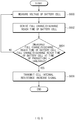
- FIG. 5 is a flowchart illustrating a method for determining a battery cell abnormality according to an embodiment of the present invention.
- the magnetic field generated by the current flowing through the battery cell is collected by the magnetic field shield unit.
- the collected magnetic field is measured by the magnetic field measurement unit 302, and the measured magnetic field strength is transmitted to the control unit 308.
- the control unit 308 receiving the measured magnetic field strength calculates a current flowing in the battery cell in real time using the measured magnetic field strength (S500).
- the current of the battery cell may be indirectly calculated using the measured magnetic field, for example, by the Biot-Savart law.
- the magnetic field strength measured by the magnetic field measurement unit 302 may be received by the control unit 308, and the control unit 308 may calculate a current flowing in the corresponding battery cell in real time.
- the control unit 308 accumulates the calculated current for a predetermined time to calculate the capacity of the battery cell (S502).
- the equation for accumulating the calculated current for a predetermined time is as follows: ⁇ t 0 t 1 ⁇ i dt Ah
- the control unit 308 determines whether the difference between the calculated capacity of the battery cell and the capacity at the time of production of the corresponding battery cell, which is stored in the storage unit 310, exceeds a preset threshold (S504).
- the temperature measurement unit 306 may measure the temperature of the battery cell.
- the temperature measurement unit 306 may be a thermistor, for example.
- the battery cell may change a battery charge state value (e.g., SOC) according to a temperature. Therefore, when calculating the capacity of the battery cell according to the current, it is also possible to calculate the capacity of the battery cell by referring to the temperature of the battery cell.
- the capacity change of the battery cell according to the temperature of the battery cell may be calculated using the capacity of the battery cell according to the temperature of the battery cell determined by the experiment as a reference table.
- control unit 308 determines that the difference between the calculated capacity of the battery cell and the capacity at the time of production of the corresponding battery cell stored in the storage unit 310 does not exceed a preset threshold, it calculates the magnetic field measurement generated by the current flowing through the battery cell as the current value of the battery cell.
- control unit 308 determines that the difference between the calculated capacity of the battery cell and the capacity at the time of production of the corresponding battery cell stored in the storage unit 310 exceeds a preset threshold, it causes the communication unit 312 to transmit a capacity deterioration notification signal of the battery cell (S506).
- FIG 6 is a flowchart illustrating a method for determining a battery cell abnormality according to another embodiment of the present invention.
- the voltage measurement unit 304 measures the voltage of the battery cell (S600). Since the voltage measurement unit 304 measures the voltage of the battery cell, it is disposed over the negative terminal and the positive terminal of the battery cell. The voltage of the battery cell measured by the voltage measurement unit 304 is transmitted to the control unit 308.
- the control unit 308 which receives the measured voltage of the battery cell from the voltage measurement unit 304 in real time, uses the received voltage of the battery cell to measure the time taken for the battery cell to reach full charge from a fully discharged state. That is, the control unit 308 derives the full charge/discharge reach time of the battery cell (S602).
- control unit 308 compares the derived charging and discharging time of the battery cell with the charge/discharge reach time of the battery cell at the time of production of the battery cell, which is stored in advance. The control unit 308 determines whether the difference between the derived charge/discharge reach time of the battery cell and the pre-stored charge/discharge reach time of the battery cell at the time of production of the battery cell exceeds a preset threshold (S604).
- control unit 308 causes the communication unit 312 to transmit an internal resistance increase signal of the battery cell (S606).
- control unit 308 causes the voltage measurement unit 304 to measure the voltage of the battery cell.
- FIG 7 is a block diagram of a battery cell abnormality determining apparatus according to another embodiment of the present invention.
- the battery cell abnormality determining apparatus 700 includes a magnetic field shield unit 701, a magnetic field measurement unit 702, a voltage measurement unit 704, a temperature measurement unit 706, and a communication unit. 708.
- the magnetic field shield unit 701 collects a magnetic field flowing in the battery cell in order to measure the current of the battery cell in units of a battery cell.
- the magnetic field shield unit 701 may be formed to surround the lower surface and the side surface of the tab of the battery cell with a predetermined distance to accurately measure the magnetic field generated when current flows in the battery cell.
- the magnetic field shield unit 701 may be composed of a nickel alloy, for example.
- the magnetic field measurement unit 702 measures a magnetic field around the battery cell generated when current flows in the battery cell.
- the current of the battery cell may be indirectly calculated using the measured magnetic field, for example, by the Biot-Savart law.
- the voltage measurement unit 704 measures the voltage of the battery cell. Since the voltage measurement unit 704 measures the voltage of the battery cell, it is disposed over the negative terminal and the positive terminal of the battery cell.
- the temperature measurement unit 706 may measure the temperature of the battery cell.
- the temperature measurement unit 306 may be a thermistor, for example. Since the battery cell may change a battery charging state value (e.g., SOC) according to the temperature, when calculating the capacity of the battery cell according to the current, it is also possible to calculate the capacity of the battery cell by referring to the temperature of the battery cell. The capacity change of the battery cell according to the temperature of the battery cell may be calculated using the capacity of the battery cell according to the temperature of the battery cell determined by the experiment as a reference table.
- SOC battery charging state value
- the communication unit 708 transmits a magnetic field strength, a voltage value, and a temperature respectively measured by the magnetic field measurement unit 702, the voltage measurement unit 704, and the temperature measurement unit 706 to the battery management system (BMS) 710.
- the communication unit 708 may transmit the magnetic field strength, voltage value, and temperature of the battery cell by wireless or wire to the BMS 710.
- the communication unit 708 transmits identification information on the battery cell stored in the storage unit 709, an initial production capacity of the battery cell, and full charge/discharge reach time information at the time of production of the battery cell together.
- the storage unit 709 stores identification information (e.g., ID) of the battery cell to which the battery cell abnormality determining apparatus is connected.
- the storage unit 709 stores an initial production capacity of the battery cell.
- the initial production capacity can be derived from a capacity table according to the voltage of the battery cell. Accordingly, a capacity table according to the current of the battery cell at the time of production or a capacity table according to the voltage of the battery cell may be stored in the storage unit 709.
- the storage unit 709 stores the full charge/discharge reach time information at the time of production of the battery cell.
- the current measurement unit may measure the current of the battery cell. In this case, the current value measured by the current measurement unit is transmitted to the BMS.
- the communication unit 712 of the BMS 710 receives a magnetic field strength, a voltage value, and a temperature of a specific battery cell from the battery cell abnormality determining apparatus 700 by wireless or wired.
- the communication unit 712 transmits, to the control unit 714, the received magnetic field strength, voltage value, temperature of the battery cell, identification information on the battery cell, capacity information at the time of production of the battery cell, and full charge reach time information at the time of production of the battery cell.
- the control unit 714 calculates a real time current of the battery cell using the received magnetic field value of the battery cell.
- the control unit 714 calculates the capacity of the battery cell by accumulating the calculated current of the battery cell for a predetermined time. In this case, the control unit 714 may reflect the capacity of the battery cell using the temperature measured by the temperature measurement unit 706.
- the capacity change reference table of the battery cell according to the temperature of the battery cell determined through the experiment in advance may be used.
- control unit 714 compares the capacity of the battery cell with the capacity of the battery cell at the time of production of the battery cell, which is stored in advance.
- the capacity of the battery cell at the time of production of the battery cell is stored in the storage unit 709. If the difference between the derived capacity of the battery cell and the stored capacity of the battery cell at the time of production of the battery cell exceeds the preset threshold, the control unit 714 determines that the capacity of the battery cell has been deteriorated.
- control unit 714 calculates the full charge/discharge reach time of the battery cell using the voltage measured by the voltage measurement unit 704. If the difference between the calculated full charge and discharge reach time of the battery cell and the full charge and discharge reach time at the time of production of the battery cell exceeds a preset threshold, the control unit 714 determines that the battery cell is deteriorated due to an increase in the internal resistance of the battery cell.
- the capacity and full charge/discharge reach time of the corresponding battery cell at the time of production are stored in the storage unit 709, but may be stored in a separate storage unit (not shown) of the BMS.
- the storage unit 709 stores the capacity of the corresponding battery cell at the time of production and the full charge/discharge reach time and the BMS receives the capacity and full charge/discharge reach time of the corresponding battery cell at the time of production, they may be stored together with the identification information on the corresponding battery cell for later use.
- FIG 8 is a flowchart illustrating a method for determining a battery cell abnormality according to another embodiment of the present invention.
- the magnetic field measurement unit 702 measures a magnetic field around the battery cell generated when current flows in the battery cell (S800).
- the magnetic field generated around the battery cell may be shielded by the magnetic field shield unit 701.
- the voltage of the battery cell is measured by the voltage specifying unit 704 (S802). Since the voltage measurement unit 704 measures the voltage of the battery cell, it is disposed over the negative terminal and the positive terminal of the battery cell.
- the temperature of the battery cell is measured by the temperature measurement unit 706 (S802).
- the temperature measurement unit 706 may be a thermistor, for example. Since the battery cell may change a battery charging state value (e.g., SOC) according to the temperature, when calculating the capacity of the battery cell according to the current, it is also possible to calculate the capacity of the battery cell by referring to the temperature of the battery cell.
- the capacity change of the battery cell according to the temperature of the battery cell may be calculated using the capacity of the battery cell according to the temperature of the battery cell determined by the experiment as a reference table.
- the communication unit 708 transmits, to the BMS, identification information on the battery cell, an initial production capacity of the battery cell, and full charge/discharge reach time information at the time of production of the battery cell together with the measured magnetic field strength, voltage, and temperature of the battery cell (S806).
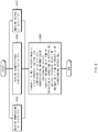
- FIG 9 is a flowchart illustrating a method for determining a battery cell abnormality according to another embodiment of the present invention.
- the BMS 710 receives, from the battery cell abnormality determining apparatus of each of a plurality of battery cells, identification information on the battery cell, an initial production capacity of the battery cell, and full charge/discharge reach time information at the time of production of the battery cell together with the measured magnetic field strength, voltage, and temperature of the battery cell (S900).
- the communication unit 712 of the BMS 710 receives information from each battery cell abnormality determining apparatus by wireless or wired.
- the control unit 714 of the BMS 710 calculates a current flowing in the battery cell in real time using the received magnetic field strength (S902).
- the current of the battery cell may be indirectly calculated using the measured magnetic field, for example, by the Biot-Savart law.
- control unit 714 accumulates the calculated current for a predetermined time to calculate the capacity of the battery cell (S904).
- the equation for accumulating the calculated current for a predetermined time is as follows: ⁇ t 0 t 1 ⁇ i dt Ah
- the control unit 714 calculating the capacity of the specific battery cell determines whether the difference between the calculated capacity of the battery cell and the capacity at the time of production of the battery cell exceeds a preset threshold (S906).
- the battery cell may change a battery charging state value (e.g., SOC) according to the temperature
- a battery charging state value e.g., SOC
- the capacity change of the battery cell according to the temperature of the battery cell may be calculated using the capacity of the battery cell according to the temperature of the battery cell determined by the experiment as a reference table.
- control unit 714 determines that the difference between the calculated capacity of the battery cell and the capacity at the time of production of the battery cell does not exceed a preset threshold, it receives information on the battery cell from the battery cell abnormality determining apparatus in real time again.
- control unit 714 determines that the difference between the calculated capacity of the battery cell and the capacity at the time of production of the battery cell exceeds a preset threshold, it causes the communication unit 712 to transmit the capacity deterioration notification signal of the battery cell to the higher level controller 2 (S906).
- control unit 714 also calculates the full charge/discharge reach time of the battery cell using the received voltage of the specific battery cell. In addition, the control unit 714 determines whether the difference between the calculated full charge/discharge reach time of the specific battery cell and the full charge/discharge reach time at the time of production of the battery cell exceeds a preset threshold value (S908).
- control unit 714 causes the communication unit 712 to transmit the internal resistance increase signal of the battery cell to the higher level controller 2 (S910).
- control unit 308 receives the information on the battery cell from the battery cell abnormality determining apparatus in real time again.
- FIG. 10 is a block diagram illustrating a hardware configuration of a battery management system according to an embodiment of the present invention.
- a battery management system 1000 may include a microcontroller (MCU) 1010 for controlling various processes and components, a memory 1040 in which an operating system program and various programs (for example, a battery pack abnormality diagnosis program or a battery pack temperature estimation program) are recorded, an input/output interface 1030 for providing an input interface and an output interface between the battery cell module and/or the semiconductor switching element, and a communication interface 1020 capable of communicating with the outside through a wired or wireless communication network.
- the computer program according to the present invention may be recorded in the memory 1040 and processed by the microcontroller 1010 to be implemented as a module for performing the respective functional blocks shown in FIG 3 and FIG 7 .
Landscapes
- General Physics & Mathematics (AREA)
- Physics & Mathematics (AREA)
- Engineering & Computer Science (AREA)
- Power Engineering (AREA)
- Mechanical Engineering (AREA)
- Transportation (AREA)
- Sustainable Energy (AREA)
- Sustainable Development (AREA)
- Life Sciences & Earth Sciences (AREA)
- Secondary Cells (AREA)
- Charge And Discharge Circuits For Batteries Or The Like (AREA)
- Measuring Instrument Details And Bridges, And Automatic Balancing Devices (AREA)
- Tests Of Electric Status Of Batteries (AREA)
Applications Claiming Priority (2)
| Application Number | Priority Date | Filing Date | Title |
|---|---|---|---|
| KR1020190017277A KR102497448B1 (ko) | 2019-02-14 | 2019-02-14 | 배터리 셀 이상 판단 장치 및 방법 |
| PCT/KR2020/001039 WO2020166840A1 (ko) | 2019-02-14 | 2020-01-21 | 배터리 셀 이상 판단 장치 및 방법 |
Publications (2)
| Publication Number | Publication Date |
|---|---|
| EP3901643A1 true EP3901643A1 (de) | 2021-10-27 |
| EP3901643A4 EP3901643A4 (de) | 2022-03-30 |
Family
ID=72045023
Family Applications (1)
| Application Number | Title | Priority Date | Filing Date |
|---|---|---|---|
| EP20756083.0A Pending EP3901643A4 (de) | 2019-02-14 | 2020-01-21 | Vorrichtung und verfahren zur bestimmung einer batteriezellenabnormalität |
Country Status (6)
| Country | Link |
|---|---|
| US (1) | US11774515B2 (de) |
| EP (1) | EP3901643A4 (de) |
| JP (2) | JP2022507511A (de) |
| KR (1) | KR102497448B1 (de) |
| CN (1) | CN113597562A (de) |
| WO (1) | WO2020166840A1 (de) |
Families Citing this family (2)
| Publication number | Priority date | Publication date | Assignee | Title |
|---|---|---|---|---|
| KR20220071007A (ko) | 2020-11-23 | 2022-05-31 | 주식회사 엘지에너지솔루션 | 배터리 팩 진단 방법 |
| WO2024090776A1 (ko) * | 2022-10-26 | 2024-05-02 | 주식회사 엘지에너지솔루션 | 배터리 제조 방법 및 배터리 제조 시스템 |
Citations (5)
| Publication number | Priority date | Publication date | Assignee | Title |
|---|---|---|---|---|
| US20030006735A1 (en) * | 2001-05-29 | 2003-01-09 | Canon Kabushiki Kaisha | Detecting method for detecting internal information of a rechargeable battery, detecting apparatus for detecting internal information of a rechargeable battery, apparatus in which said detecting method is applied, apparatus including said detecting apparatus, and storage medium in which a software program of said detecting method is stored |
| JP2008292403A (ja) * | 2007-05-28 | 2008-12-04 | Asahi Kasei Electronics Co Ltd | 組電池の異常検出方法及びその異常検出装置 |
| JP5167521B2 (ja) * | 2008-11-28 | 2013-03-21 | 旭化成エレクトロニクス株式会社 | 組電池及びその組電池を用いた電子機器 |
| US20140103934A1 (en) * | 2009-12-25 | 2014-04-17 | Kabushiki Kaisha Toshiba | Battery diagnosis device and method |
| US20150293183A1 (en) * | 2012-11-30 | 2015-10-15 | Sanyo Electric Co., Ltd. | Battery management device, power supply, and soc estimation method |
Family Cites Families (27)
| Publication number | Priority date | Publication date | Assignee | Title |
|---|---|---|---|---|
| JPH11329512A (ja) | 1998-05-20 | 1999-11-30 | Fuji Photo Film Co Ltd | 二次電池の容量劣化判断方法およびその判断装置 |
| TW535308B (en) * | 2000-05-23 | 2003-06-01 | Canon Kk | Detecting method for detecting internal state of a rechargeable battery, detecting device for practicing said detecting method, and instrument provided with said |
| JP4401734B2 (ja) * | 2002-10-11 | 2010-01-20 | キヤノン株式会社 | 二次電池の内部抵抗検知方法、内部抵抗検知装置、内部抵抗検知プログラム及び該プログラムを収めた媒体 |
| US7190171B2 (en) | 2002-10-11 | 2007-03-13 | Canon Kabushiki Kaisha | Detecting method and detecting apparatus for detecting internal of rechargeable battery, rechargeable battery pack having said detecting apparatus therein, apparatus having said detecting apparatus therein, program in which said detecting method is incorporated, and medium in which said program is stored |
| JP3997908B2 (ja) * | 2002-12-13 | 2007-10-24 | トヨタ自動車株式会社 | 電流センサオフセット値算出装置およびその方法 |
| JP5058925B2 (ja) * | 2008-09-18 | 2012-10-24 | 矢崎総業株式会社 | 電流センサ |
| JP2010217070A (ja) | 2009-03-18 | 2010-09-30 | Toyota Motor Corp | 容量推定装置および車両 |
| WO2010118039A1 (en) * | 2009-04-06 | 2010-10-14 | The University Of Akron | Battery pack manager unit and method for using same to extend the life of a battery pack |
| US9285433B2 (en) * | 2010-06-24 | 2016-03-15 | Toyota Jidosha Kabushiki Kaisha | Battery management system, battery management apparatus, method of reusing battery, and information communication terminal apparatus |
| JP6147668B2 (ja) | 2010-11-02 | 2017-06-14 | ナビタス ソリューションズ,インコーポレイテッド | スマート電池管理システムのための無線電池エリアネットワーク |
| JP5868026B2 (ja) | 2011-05-24 | 2016-02-24 | 株式会社東芝 | 超音波診断装置 |
| JP2012247339A (ja) | 2011-05-30 | 2012-12-13 | Renesas Electronics Corp | 半導体集積回路およびその動作方法 |
| US9395418B2 (en) | 2011-06-13 | 2016-07-19 | Methode Electronics, Inc. | System and method for determining the state of health of electrochemical battery cells |
| JP5765375B2 (ja) * | 2013-07-25 | 2015-08-19 | トヨタ自動車株式会社 | 制御装置及び制御方法 |
| JP6102609B2 (ja) * | 2013-07-29 | 2017-03-29 | 株式会社豊田自動織機 | 電池交換管理システム及び方法 |
| KR20150029204A (ko) | 2013-09-09 | 2015-03-18 | 삼성에스디아이 주식회사 | 배터리 팩, 배터리 팩을 포함하는 장치, 및 배터리 팩의 관리 방법 |
| JP2016024170A (ja) | 2014-07-24 | 2016-02-08 | 日立オートモティブシステムズ株式会社 | 電池制御装置 |
| KR101738601B1 (ko) | 2014-11-03 | 2017-05-22 | 주식회사 엘지화학 | 배터리 용량 퇴화 추정 장치 |
| KR102338460B1 (ko) | 2015-01-22 | 2021-12-13 | 삼성전자주식회사 | 배터리의 상태를 추정하는 방법 및 장치 |
| KR101750478B1 (ko) | 2015-06-01 | 2017-06-23 | 주식회사 엘지화학 | 전지셀의 용량 등급을 산정하는 방법 |
| CN107852019B (zh) | 2015-07-21 | 2021-04-27 | 株式会社村田制作所 | 充电方法、电池装置、充电装置、劣化诊断方法、电池组、电动车辆和蓄电装置 |
| CN105006864A (zh) | 2015-08-04 | 2015-10-28 | 广州广日电气设备有限公司 | 储能供电系统和方法 |
| KR102035683B1 (ko) | 2015-11-30 | 2019-10-23 | 주식회사 엘지화학 | 배터리 셀 벨런싱 장치 및 방법 |
| KR102225896B1 (ko) | 2016-07-29 | 2021-03-09 | 주식회사 엘지화학 | 배터리 셀을 이용한 저전압 전원 공급 장치 및 방법 |
| JP2018068081A (ja) | 2016-10-21 | 2018-04-26 | 京セラ株式会社 | 二次電池の充電時間の予測装置および予測方法 |
| JP6624012B2 (ja) | 2016-11-04 | 2019-12-25 | トヨタ自動車株式会社 | リチウムイオン二次電池の制御システム |
| CN112055912A (zh) * | 2018-06-01 | 2020-12-08 | 住友电气工业株式会社 | 电池管理装置、电池信息处理系统以及电池信息处理方法 |
-
2019
- 2019-02-14 KR KR1020190017277A patent/KR102497448B1/ko active IP Right Grant
-
2020
- 2020-01-21 EP EP20756083.0A patent/EP3901643A4/de active Pending
- 2020-01-21 JP JP2021526503A patent/JP2022507511A/ja active Pending
- 2020-01-21 US US17/420,203 patent/US11774515B2/en active Active
- 2020-01-21 CN CN202080007262.4A patent/CN113597562A/zh active Pending
- 2020-01-21 WO PCT/KR2020/001039 patent/WO2020166840A1/ko unknown
-
2023
- 2023-12-15 JP JP2023212493A patent/JP2024029001A/ja active Pending
Patent Citations (5)
| Publication number | Priority date | Publication date | Assignee | Title |
|---|---|---|---|---|
| US20030006735A1 (en) * | 2001-05-29 | 2003-01-09 | Canon Kabushiki Kaisha | Detecting method for detecting internal information of a rechargeable battery, detecting apparatus for detecting internal information of a rechargeable battery, apparatus in which said detecting method is applied, apparatus including said detecting apparatus, and storage medium in which a software program of said detecting method is stored |
| JP2008292403A (ja) * | 2007-05-28 | 2008-12-04 | Asahi Kasei Electronics Co Ltd | 組電池の異常検出方法及びその異常検出装置 |
| JP5167521B2 (ja) * | 2008-11-28 | 2013-03-21 | 旭化成エレクトロニクス株式会社 | 組電池及びその組電池を用いた電子機器 |
| US20140103934A1 (en) * | 2009-12-25 | 2014-04-17 | Kabushiki Kaisha Toshiba | Battery diagnosis device and method |
| US20150293183A1 (en) * | 2012-11-30 | 2015-10-15 | Sanyo Electric Co., Ltd. | Battery management device, power supply, and soc estimation method |
Non-Patent Citations (1)
| Title |
|---|
| See also references of WO2020166840A1 * |
Also Published As
| Publication number | Publication date |
|---|---|
| US11774515B2 (en) | 2023-10-03 |
| KR20200099364A (ko) | 2020-08-24 |
| JP2024029001A (ja) | 2024-03-05 |
| US20220065944A1 (en) | 2022-03-03 |
| CN113597562A (zh) | 2021-11-02 |
| JP2022507511A (ja) | 2022-01-18 |
| KR102497448B1 (ko) | 2023-02-08 |
| EP3901643A4 (de) | 2022-03-30 |
| WO2020166840A1 (ko) | 2020-08-20 |
Similar Documents
| Publication | Publication Date | Title |
|---|---|---|
| EP2700966B1 (de) | Vorrichtung und verfahren zur bestimmung eines batteriezustands | |
| KR20190075684A (ko) | 배터리의 전하 균형을 탐지하는 배터리 모니터링 장치 및 방법 | |
| US10591550B2 (en) | Secondary-battery monitoring device and prediction method of battery capacity of secondary battery | |
| JP6298920B2 (ja) | 電池制御装置 | |
| CN109791181B (zh) | 蓄电元件的soc估计装置、蓄电装置、蓄电元件的soc估计方法 | |
| KR20040016808A (ko) | 재충전가능한 전지의 내부상태를 검출하는 검출장치를가지는 전력저장장치 | |
| EP3678256B1 (de) | Vorrichtung und verfahren zum testen einer sekundärbatterie | |
| CN114096433B (zh) | 管理电池设备和管理电池方法 | |
| US20170199250A1 (en) | Apparatus and method for estimating open circuit voltage | |
| US11187755B2 (en) | Apparatus and method for estimating SOC of battery | |
| JP2024029001A (ja) | バッテリーセルの異常判断装置及び方法 | |
| EP3958006A1 (de) | Batteriediagnosevorrichtung und -verfahren | |
| EP3748388B1 (de) | Vorrichtung und verfahren zur diagnose eines stromsensors | |
| US11340305B2 (en) | Apparatus and method for estimating state of secondary battery | |
| US20230402666A1 (en) | Abnormality detection method, abnormality detection device, energy storage apparatus, and computer program | |
| KR20190028201A (ko) | 배터리 충방전 전압 조절 장치 및 방법 | |
| EP4194868A1 (de) | Verfahren zur vorhersage eines entladungsspannungsgraphen und batteriesystem damit | |
| EP4198536A1 (de) | Batterieverwaltungsvorrichtung und -verfahren | |
| US20240066993A1 (en) | Battery Diagnosis Device, Battery Management System, Battery Pack, Electric Vehicle And Battery Diagnosis Method | |
| US9618544B2 (en) | System and method for verifying a reference voltage for battery cell monitoring | |
| EP4365613A1 (de) | Batteriepack und betriebsverfahren dafür |
Legal Events
| Date | Code | Title | Description |
|---|---|---|---|
| STAA | Information on the status of an ep patent application or granted ep patent |
Free format text: STATUS: THE INTERNATIONAL PUBLICATION HAS BEEN MADE |
|
| PUAI | Public reference made under article 153(3) epc to a published international application that has entered the european phase |
Free format text: ORIGINAL CODE: 0009012 |
|
| STAA | Information on the status of an ep patent application or granted ep patent |
Free format text: STATUS: REQUEST FOR EXAMINATION WAS MADE |
|
| 17P | Request for examination filed |
Effective date: 20210721 |
|
| AK | Designated contracting states |
Kind code of ref document: A1 Designated state(s): AL AT BE BG CH CY CZ DE DK EE ES FI FR GB GR HR HU IE IS IT LI LT LU LV MC MK MT NL NO PL PT RO RS SE SI SK SM TR |
|
| A4 | Supplementary search report drawn up and despatched |
Effective date: 20220302 |
|
| RAP3 | Party data changed (applicant data changed or rights of an application transferred) |
Owner name: LG ENERGY SOLUTION, LTD. |
|
| RIC1 | Information provided on ipc code assigned before grant |
Ipc: G01R 19/165 20060101ALI20220224BHEP Ipc: G01R 31/3828 20190101ALI20220224BHEP Ipc: G01R 1/18 20060101ALI20220224BHEP Ipc: G01R 15/20 20060101ALI20220224BHEP Ipc: G01R 31/387 20190101ALI20220224BHEP Ipc: G01R 31/396 20190101ALI20220224BHEP Ipc: G01R 31/392 20190101AFI20220224BHEP |
|
| DAV | Request for validation of the european patent (deleted) | ||
| DAX | Request for extension of the european patent (deleted) | ||
| GRAP | Despatch of communication of intention to grant a patent |
Free format text: ORIGINAL CODE: EPIDOSNIGR1 |
|
| STAA | Information on the status of an ep patent application or granted ep patent |
Free format text: STATUS: GRANT OF PATENT IS INTENDED |