EP3901409B1 - Intelligenter gesteinsankerantrieb - Google Patents
Intelligenter gesteinsankerantrieb Download PDFInfo
- Publication number
- EP3901409B1 EP3901409B1 EP20170773.4A EP20170773A EP3901409B1 EP 3901409 B1 EP3901409 B1 EP 3901409B1 EP 20170773 A EP20170773 A EP 20170773A EP 3901409 B1 EP3901409 B1 EP 3901409B1
- Authority
- EP
- European Patent Office
- Prior art keywords
- data
- rotation
- bolt
- driver socket
- rotated
- Prior art date
- Legal status (The legal status is an assumption and is not a legal conclusion. Google has not performed a legal analysis and makes no representation as to the accuracy of the status listed.)
- Active
Links
Images
Classifications
-
- E—FIXED CONSTRUCTIONS
- E21—EARTH OR ROCK DRILLING; MINING
- E21D—SHAFTS; TUNNELS; GALLERIES; LARGE UNDERGROUND CHAMBERS
- E21D20/00—Setting anchoring-bolts
-
- G—PHYSICS
- G01—MEASURING; TESTING
- G01L—MEASURING FORCE, STRESS, TORQUE, WORK, MECHANICAL POWER, MECHANICAL EFFICIENCY, OR FLUID PRESSURE
- G01L5/00—Apparatus for, or methods of, measuring force, work, mechanical power, or torque, specially adapted for specific purposes
- G01L5/0028—Force sensors associated with force applying means
- G01L5/0042—Force sensors associated with force applying means applying a torque
-
- G—PHYSICS
- G01—MEASURING; TESTING
- G01P—MEASURING LINEAR OR ANGULAR SPEED, ACCELERATION, DECELERATION, OR SHOCK; INDICATING PRESENCE, ABSENCE, OR DIRECTION, OF MOVEMENT
- G01P13/00—Indicating or recording presence, absence, or direction, of movement
-
- G—PHYSICS
- G01—MEASURING; TESTING
- G01P—MEASURING LINEAR OR ANGULAR SPEED, ACCELERATION, DECELERATION, OR SHOCK; INDICATING PRESENCE, ABSENCE, OR DIRECTION, OF MOVEMENT
- G01P3/00—Measuring linear or angular speed; Measuring differences of linear or angular speeds
Definitions
- the present invention relates to rock bolts for reinforcement of formations, such as rock strata, and specifically to technology for monitoring installation of such bolts, especially monitoring of rotation of a nut, or similar, attached to the outer end portion of the bolt.
- rock bolts are commonly used for reinforcement of tunnel roofs and for stabilization of rock walls, slopes and dikes.
- rock bolts or anchors are used depending for example on the type of formation to be reinforced.
- a common type of rock bolt is the hydraulically expandable rock bolt provided with an expandable body to be driven into a formation and thereafter expanded by introduction of a pressurized pressure medium such that the expandable body presses against the wall of the borehole and thereby engages the formation.
- a hydraulically expandable rock bolt is known from CZ 25706 U1 .
- rock bolt Another type of rock bolt is the friction bolt.
- a rock bolt may be driven into a formation by a driving device such as a jumbo.
- the mechanically expandable bolt comprises an elongate expandable outer body, sometimes referred to as a split tube, and a central rod extending inside the outer body from a trailing portion provided with a nut to a leading portion operatively connected to an expansion mechanism for expanding the outer body upon rotation of the central rod.
- the driving device is operated to repeatedly impact the outer body of the bolt, thereby forcing the outer body into the formation.
- the bolt is expanded by rotation of the nut, which causes rotation of the central rod such that the expansion mechanism causes expansion of the outer body.
- the nut may be a blind nut such that the nut can first be screwed onto a thread at the trailing portion of the central rod, wherein the central rod eventually bottoms out in the blind nut, thereby preventing further relative rotation between the central rod and the blind nut. This allows torque to be applied to the nut and further to the central rod for tensioning of the expansion mechanism of the bolt.
- Other means for preventing co-rotation between the central rod and nut are feasible, such as thread-locking fluid or a shearing pin, wherein a standard nut with through hole may be used instead of a blind nut.
- Some friction bolts comprise an outer body but no expansion mechanism, wherein the bolt is forced into the formation with a press-fit to anchor the bolt in the formation.
- Non-expandable bolts such as resin bolts, may also need rotation after insertion by rotation of a nut attached to a trailing portion of the bolt.
- AU2010223134B2 discloses a mechanically expandable friction bolt. Further exemplary driver sockets are found in documents US2007144781A1 and US2015218947A1 .
- Each nut should preferably be rotated a predetermined number of revolutions, or to a predetermined torque. Rotating the nut too few revolutions may lead to the bolt not expanding enough thereby engaging the formation with a high enough force. On the other hand, rotating the nut too many revolutions may lead to cracks in the formation, thereby reducing the strength of the formation.
- the mining machine carrying a driver socket is provided with a torque control device configured to allow the operator to set a predetermined target torque to apply to the driver socket for rotation of the nut of the rock bolt.
- a torque control device configured to allow the operator to set a predetermined target torque to apply to the driver socket for rotation of the nut of the rock bolt.
- the operator may still forget to activate rotation of the driver socket after the bolt has been driven into the formation.
- An object of the invention is to enable improved control of rock bolt installation to ensure that the driver socket has been adequately rotated for correct installation of each rock bolt.
- a driver socket for installation of a ground reinforcement bolt.
- the driver socket comprises a rotation sensor for measuring rotation of the driver socket.
- the driver socket comprises a processing unit configured to receive a signal from the rotation sensor and configured to derive, based on the signal from the rotation sensor, rotation data related to the number of revolutions the driver socket has been rotated.
- the rotation sensor Upon rotation of the driver socket, the rotation sensor measures rotation of the driver socket and emits a signal. The signal is received by the processing unit which derives rotation data related to the number of revolutions the driver socket has been rotated.
- the processing unit which derives rotation data related to the number of revolutions the driver socket has been rotated.
- the rotation data is made available independently of what type of machine the driver socket is attached to.
- the driver socket enables a plug-n-play approach to measuring rotation of the bolt installed and enables monitoring of correct installation of ground reinforcement bolts using any existing machine carrying the novel driver socket.
- the rotation data may comprise data describing average rotational speed over a predetermined period of time, data describing number of revolutions the driver socket has rotated at one or more specific points in time, or data describing if the driver socket has been rotated or not.
- Typical examples of rotation data are the number of revolutions the driver socket has been rotated, the average rotational speed or acceleration data. Both average speed and acceleration data can be used to derive the number of revolutions driver socket has been rotated.
- the rotation sensor comprises a gyroscope and/or an accelerometer and/or an inclinometer.
- the driver socket further comprises a wireless transmitter or transceiver configured to emit a signal comprising the rotation data.
- remote reception of the rotation data is enabled, such that a remote entity can be used to monitor rotation of a ground reinforcement bolt in real time and without any wired or direct physical contact to the driver socket rotated.
- this object is also achieved by a computer implemented method of monitoring installation of a ground reinforcement bolt, wherein the method comprises receiving rotation data from one or more driver sockets according to the first aspect, and comprises a) recording the rotation data to a data carrier, and b) deriving from the rotation data a rotation value describing the number of revolutions the driver socket has been rotated, emitting a first signal if the rotation value exceeds a lower threshold value defining a minimum number of revolutions the driver socket should be rotated for correct installation, and/or creating or updating a data record on a data carrier if the rotation value exceeds the lower threshold value, said data record comprising an identifier for the bolt currently rotated and data indicating that the bolt has been rotated the required number of revolutions.
- rotation data is obtained from one or more driver sockets according to the first aspect, and used to determine whether to emit a signal indicating that the ground reinforcement bolt has been rotated enough for it to be considered correctly installed or not.
- the method comprises determining a rotation value describing the number of revolutions the driver socket has been rotated. This may be as simple as using a number of revolutions already given explicitly by the rotation data but may require calculation of revolutions based on average rotational speed and/or acceleration data. Once the number of revolutions the driver socket has been rotated has been determined, it is compared to the threshold value.
- a data record can be created or updated such that a person or system can easily consult the data records on the data carrier to see if a bolt is correctly installed or not.
- the driver socket can be used to installing another bolt, wherein the data records of the data carrier are used to keep track of which bolts have been correctly installed.
- the method may further comprise emitting a second signal if the rotation value exceeds an upper threshold value defining a maximum number of revolutions the driver socket can be rotated for correct installation and/or creating or updating a data record on a data carrier if the rotation value exceeds the upper threshold value, said data record comprising an identifier for the bolt currently rotated and data indicating that the bolt has been over-rotated.
- the method may further comprise recording the duration of the installation of each bolt and creating or updating a data record on a data carrier if the rotation value exceeds the lower threshold value, said data record comprising the duration of installation of the bolt currently rotated and an identifier for the bolt currently rotated.
- the electronics of the driver socket may thus also be used to keep track of the duration of installation of each ground reinforcement bolt by recording when installation of the bolt starts and stops respectively. Any one or more suitable durations can be measured for each bolt, such as from the start of driving the bolt into the ground and/or the start of rotation of the driver socket. Also, the end of the duration may be the time of detection of the bolt having been rotated a number of revolutions higher than the threshold value and/or it may be the time when the bolt has been inserted into the bore in the ground but before rotation of the driver socket commences. The duration can for example be used for benchmarking and statistics purposes to improve installation efficiency and quality.
- the method may comprise receiving torque data from a torque sensor configured to measure torque applied to the driver socket, and deriving rotational resistance data based on the torque data and the rotation data.
- rotational resistance data By so deriving rotational resistance data, it is possible to verify if rotational resistance is suddenly lowered upon further rotation of the driver socket, typically indicating something gone wrong during installation such as formation of cracks around the reinforcement bolt. Also, the rotational resistance data enables follow-up based on resistance vs current type of ground.
- the torque sensor may be integrated with a machine carrying the driver socket, such as a jumbo.
- the machine carrying the driver socked at installation of a ground reinforcement bolt is typically provided with a torque adjustment means allowing the torque applied by the machine to the driver socket to be set as appropriate based on experience.
- Torque data is thus available directly or indirectly from the machine carrying the driver socket and by adapting the method of installing the ground reinforcement bolt to also comprise a step of deriving rotational resistance data for each bolt installed, it is possible to get a better understanding of the installation of each bolt and take measures to correct any deviations. For example, if the rotational resistance suddenly decreases after a long increase it may be due to the bolt having cracked the ground such that the bolt no longer correctly reinforces the ground as intended. One can then consider taking any appropriate measure such as replacing the ground reinforcement bolt or adding additional bolts nearby.
- the method may further comprise continuously comparing current rotational resistance to a lower resistance threshold, and
- a lower resistance threshold is used to determine deviations of interest.
- the lower resistance threshold may be a dynamically calculated threshold or it may be a predetermined threshold.
- the lower resistance threshold may be continuously calculated by continuously recording a maximum value of the rotational resistance based on the rotational resistance data and then calculate the lower resistance threshold as a predetermined fraction of the maximum value of the rotational resistance data. Since a slight variation up and down of the rotational resistance is normal it may not suffice to look for an instantaneous lowering of the torque since that may trigger a false impression of that a maximum torque has been reached and over-rotation has begun. Instead, a lower resistance threshold should be used which lower resistance threshold may be dynamically calculated as a predetermined fraction of the maximum value rather than based on a predetermined lower threshold value.
- the method may comprise continuously monitoring current rotational speed and comparing it to a predetermined upper rotational speed threshold, and a) emitting a third signal if the comparison indicates that the rotational speed exceeds the upper rotational speed threshold, and/or b) creating or updating a data record on a data carrier if comparison indicates that the rotational speed exceeds the upper rotational speed threshold, said data record comprising an identifier for the bolt currently rotated and data indicating that the rotational speed has exceeded the upper rotational speed threshold.
- the emitted first, second and/or third signal(s) may be presented using an audio communication device, such as a speaker, or using a visual communication device, such as a light source or a display unit.
- an audio communication device such as a speaker
- a visual communication device such as a light source or a display unit.
- the signal is readily comprehensible by an operator in control of the reinforcement bolt installation such that the operator knows when the bolt has been correctly installed.
- this object is also achieved by a monitoring system for monitoring installation of a ground reinforcement bolt.
- the monitoring system comprises a driver socket according to the first aspect and a computer program product configured to perform the method according to the second aspect.
- the monitoring system further comprises a mobile computing device for running the computer program product, such as a smart phone or a mobile terminal.
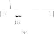
- Fig. 1 shows a simplified side view of a driver socket according to a first embodiment with dashed lines indicating central recesses respectively for receiving the bolt and for attaching to the mining machine.
- the driver socket 1 is for installation of a ground reinforcement bolt in a formation.
- the driver socket comprises a rotation sensor 2 for measuring rotation of the driver socket 1.
- the driver socket 1 also comprises a processing unit 3 configured to receive a signal from the rotation sensor 2 and configured to derive, based on the signal from the rotation sensor 2, rotation data related to the number of revolutions the driver socket 1 has been rotated.
- the rotation sensor is an electronic rotation sensor.
- the rotation data comprises data describing average rotational speed over a predetermined period of time, data describing number of revolutions the driver socket 1 has rotated at one or more specific points in time, or data describing if the driver socket 1 has been rotated or not.
- Typical examples of rotation data are the number of revolutions the driver socket has been rotated, the average rotational speed or acceleration data. Both average speed and acceleration data can be used to derive the number of revolutions driver socket has been rotated, if needed.
- the provision of such a rotation sensor on a driver socket enables a drop-in replacement for many existing types of driver sockets to provide for monitoring of bolt installation by studying the rotation data provided by the sensor.
- the rotation data can be analyzed in real-time or as a post-installation procedure to censure safe and timely bolt installation.
- the rotation sensor 2 comprises a gyroscope and/or an accelerometer and/or an inclinometer.
- the gyroscope, accelerometer and/or inclinometer is/are configured to determine the rotation data taking account of the position/orientation of the rotation sensor relative to the rotational axis of the driver socket.
- the driver socket 1 further comprises a wireless transmitter or transceiver 4 configured to emit a signal comprising the rotation data.
- the driver socket may comprise a data carrier, such as a computer memory, configured to hold rotation data in addition to emitting a signal with the rotation data.
- remote reception of the rotation data is enabled, such that a remote entity can be used to monitor rotation of a ground reinforcement bolt in real time and without any wired or direct physical contact to the driver socket rotated.
- a second aspect of the invention relates to a computer implemented method of monitoring installation of a ground reinforcement bolt.
- the method comprises: receiving rotation data from one or more driver sockets 1 as previously described and recording the rotation data to a data carrier.
- the data carrier may be integrated in the driver socket or it may be provided remotely from the data carrier, such as in a separate storage device. Examples of storage devices are cloud storage devices, handheld terminals or mining machine on-board computer systems.
- the method additionally comprises a step of deriving from the rotation data a rotation value describing the number of revolutions the driver socket 1 has been rotated.
- the method additionally comprises a step of emitting a first signal if the rotation value exceeds a lower threshold value defining a minimum number of revolutions the driver socket 1 should be rotated for correct installation. Also, the method may comprise creating or updating a data record on the data carrier if the rotation value exceeds the lower threshold value, said data record comprising an identifier for the bolt currently rotated and data indicating that the bolt has been rotated the required number of revolutions.
- the method may further comprise emitting a second signal if the rotation value exceeds an upper threshold value defining a maximum number of revolutions the driver socket 1 can be rotated for correct installation.
- the method may comprise creating or updating a data record on a data carrier if the rotation value exceeds the upper threshold value, said data record comprising an identifier for the bolt currently rotated and data indicating that the bolt has been over-rotated.
- a single data carrier may be used for all data storing needs mentioned or a plurality of data carriers may be provided instead.
- the method also comprises the optional step of recording the duration of the installation of each bolt and creating or updating a data record on a data carrier if the rotation value exceeds the lower threshold value, said data record comprising the duration of installation of the bolt currently rotated and an identifier for the bolt currently rotated.
- the installation time for each bolt is measured from when rotation is deemed to have started until installation of the bolt is deemed to be finished.
- the method comprises the optional step of receiving torque data from a torque sensor configured to measure torque applied to the driver socket 1, and deriving rotational resistance data based on the torque data and the rotation data 4.
- the torque sensor used is an eternal one integrated with the machine carrying the driver socket, i.e. the mining machine.
- the torque sensor may alternatively be provided somewhere else, such as integrated with the driver socket or mounted between the mining machine and the driver socket.
- the method further comprises continuously comparing current rotational resistance to a lower resistance threshold. Once, the comparison indicates that the rotational resistance sinks below the lower resistance threshold a third signal is emitted. Alternatively, or additionally, a data record on a data carrier is created or updated if the comparison indicates that the rotational resistance sinks below the lower resistance threshold.
- the data record comprises an identifier for the bolt currently rotated and data indicating that the torque has decreased below the lower resistance threshold.
- the lower resistance threshold is continuously calculated as a predetermined fraction of the maximum value of the rotational resistance data.
- any other suitable statistical calculation may be used to derive a suitable lower resistance threshold.
- rotation data may be used to draw the same conclusion.
- the method further comprises continuously monitoring current rotational speed and comparing it to a predetermined upper rotational speed threshold, and emitting a third signal if the comparison indicates that the rotational speed exceeds the upper rotational speed threshold.
- creating or updating a data record on a data carrier if comparison indicates that the rotational speed exceeds the upper rotational speed threshold, said data record comprising an identifier for the bolt currently rotated and data indicating that the rotational speed has exceeded the upper rotational speed threshold.
- the emitted first, second and/or third signal(s) are presented using an audio communication device in the form of a speaker, and using a visual communication device in the form of a display unit. In other embodiments, audible and/or visible presentation of emitted signals may be omitted.
- the technology is delivered in the form of a monitoring system for monitoring installation of a ground reinforcement bolt, wherein the monitoring system comprises a driver socket 1 as described above and a computer program product configured to perform the method described above.
- the system further comprises a mobile computing device for running the computer program product, such as a smart phone or a mobile terminal.
- a mobile computing device for running the computer program product, such as a smart phone or a mobile terminal.
Landscapes
- Engineering & Computer Science (AREA)
- Mining & Mineral Resources (AREA)
- Structural Engineering (AREA)
- Life Sciences & Earth Sciences (AREA)
- General Life Sciences & Earth Sciences (AREA)
- Geochemistry & Mineralogy (AREA)
- Geology (AREA)
- Details Of Spanners, Wrenches, And Screw Drivers And Accessories (AREA)
- Arrangements For Transmission Of Measured Signals (AREA)
- Earth Drilling (AREA)
- Force Measurement Appropriate To Specific Purposes (AREA)
- Connection Of Plates (AREA)
Claims (12)
- Treiberbuchse (1) für eine Installation eines Bodenverstärkungsbolzens, wobei die Treiberbuchse einen Drehsensor (2) zum Messen einer Drehung der Treiberbuchse (1) umfasst, wobei die Treiberbuchse (1) eine Verarbeitungseinheit (3) umfasst, die konfiguriert ist, um ein Signal von dem Drehsensor (2) zu empfangen, und konfiguriert ist, um basierend auf dem Signal von dem Drehsensor (2) Drehdaten abzuleiten, die sich auf die Anzahl von Umdrehungen beziehen, um die die Treiberbuchse (1) gedreht wurde, wobei der Drehsensor (2) ein Gyroskop und/oder einen Beschleunigungsmesser und/oder einen Neigungsmesser umfasst, und wobei das Gyroskop, der Beschleunigungsmesser und/oder der Neigungsmesser konfiguriert ist/sind, um die Drehdaten, die die Position/Ausrichtung des Drehsensors relativ zu der Drehachse der Treiberbuchse berücksichtigen, zu bestimmen, und
wobei die Treiberbuchse ferner einen drahtlosen Sender oder Sendeempfänger (4) umfasst, der konfiguriert ist, um ein Signal zu emittieren, umfassend die Drehdaten. - Treiberbuchse nach Anspruch 1, wobei die Drehdaten Daten, die eine durchschnittliche Drehzahl über einen vorbestimmten Zeitraum beschreiben, Daten, die eine Anzahl von Umdrehungen beschreiben, um die die Treiberbuchse (1) sich an einem oder mehreren spezifischen Zeitpunkten gedreht hat, oder
Daten umfassen, die beschreiben, ob die Treiberbuchse (1) gedreht wurde oder nicht. - Computerimplementiertes Verfahren zum Überwachen der Installation eines Bodenverstärkungsbolzens, wobei das Verfahren umfasst:Empfangen von Drehdaten von einer oder mehreren Treiberbuchsen (1) nach einem der Ansprüche 1 bis 2 unda) Aufzeichnen der Drehdaten auf einem Datenträger, undb) Ableiten, von den Drehdaten, eines Drehwerts, der die Anzahl von Umdrehungen beschreibt, um die die Treiberbuchse gedreht wurde,Emittieren eines ersten Signals, falls der Drehwert einen unteren Schwellenwert überschreitet, der eine minimale Anzahl von Umdrehungen definiert, um die die Treiberbuchse 1 für die korrekte Installation gedreht werden sollte,
und/oderErstellen oder Aktualisieren eines Datensatzes auf dem Datenträger, falls der Drehwert den unteren Schwellenwert überschreitet, der Datensatz umfassend eine Kennung für den aktuell gedrehten Bolzen und Daten, die angeben, dass der Bolzen die erforderliche Anzahl von Umdrehungen gedreht wurde. - Verfahren nach Anspruch 3, ferner umfassend das Emittieren eines zweiten Signals, falls der Drehwert einen oberen Schwellenwert überschreitet, der eine maximale Anzahl von Umdrehungen definiert, um die die Treiberbuchse (1) für die korrekte Installation gedreht werden kann, und/oder
Erstellen oder Aktualisieren eines Datensatzes auf einem Datenträger, falls der Drehwert den oberen Schwellenwert überschreitet, der Datensatz umfassend eine Kennung für den aktuell gedrehten Bolzen und Daten, die angeben, dass der Bolzen überdreht wurde. - Verfahren nach Anspruch 4, ferner umfassend das Aufzeichnen der Dauer der Installation jedes Bolzens und das Erstellen oder Aktualisieren eines Datensatzes auf einem Datenträger, falls der Drehwert den unteren Schwellenwert überschreitet, der Datensatz umfassend die Dauer der Installation des aktuell gedrehten Bolzens und eine Kennung für den aktuell gedrehten Bolzen.
- Verfahren nach einem der Ansprüche 3 bis 5, ferner umfassend das Empfangen von Drehmomentdaten von einem Drehmomentsensor, der konfiguriert ist, um ein Drehmoment zu messen, das an die Treiberbuchse (1) angelegt wird, und
Ableiten von Drehwiderstandsdaten basierend auf den Drehmomentdaten und den Drehdaten (4). - Verfahren nach Anspruch 6, wobei der Drehmomentsensor in eine Maschine integriert ist, die die Treiberbuchse trägt, wie einen Jumbo.
- Verfahren nach Anspruch 7, ferner umfassend
kontinuierliches Vergleichen des aktuellen Drehwiderstands mit einer niedrigeren Widerstandsschwelle, unda) Emittieren eines dritten Signals, falls der Vergleich angibt, dass der Drehwiderstand unter die untere Widerstandsschwelle sinkt, und/oderb) Erstellen oder Aktualisieren eines Datensatzes auf einem Datenträger, falls der Vergleich angibt, dass der Drehwiderstand unter die untere Widerstandsschwelle sinkt, der Datensatz umfassend eine Kennung für den aktuell gedrehten Bolzen und Daten, die angeben, dass das Drehmoment unter die untere Widerstandsschwelle gefallen ist. - Verfahren nach Anspruch 8, ferner umfassend das Aufzeichnen eines Maximalwerts des Drehwiderstands basierend auf den Drehwiderstandsdaten, wobei die untere Widerstandsschwelle als ein vorbestimmter Bruchteil des Maximalwerts der Drehwiderstandsdaten kontinuierlich berechnet wird.
- Verfahren nach einem der Ansprüche 3 bis 5, ferner umfassend das kontinuierliche Überwachen der aktuellen Drehzahl und das Vergleichen derselben mit einer vorbestimmten oberen Drehzahlschwelle, unda) Emittieren eines dritten Signals, falls der Vergleich angibt, dass die Drehzahl die obere Drehzahlschwelle überschreitet, und/oderb) Erstellen oder Aktualisieren eines Datensatzes auf einem Datenträger, falls der Vergleich angibt, dass die Drehzahl die obere Drehzahlschwelle überschreitet, der Datensatz umfassend eine Kennung für den aktuell gedrehten Bolzen und Daten, die angeben, dass die Drehzahl die obere Drehzahlschwelle überschritten hat.
- Verfahren nach einem der Ansprüche 3 bis 10, wobei das emittierte erste, zweite und/oder dritte Signal unter Verwendung einer Audiokommunikationsvorrichtung, wie eines Lautsprechers, oder unter Verwendung einer visuellen Kommunikationsvorrichtung, wie einer Lichtquelle oder einer Anzeigeeinheit, dargestellt wird.
- Überwachungssystem zum Überwachen der Installation eines Bodenverstärkungsbolzens, wobei das Überwachungssystem eine Treiberbuchse (1) nach einem der Ansprüche 1 bis 2 und ein Computerprogrammprodukt umfasst, das konfiguriert ist, um das Verfahren nach einem der Ansprüche 3 bis 11 durchzuführen, ferner umfassend eine mobile Rechenvorrichtung zum Ausführen des Computerprogrammprodukts, wie ein Smartphone oder ein mobiles Endgerät.
Priority Applications (10)
| Application Number | Priority Date | Filing Date | Title |
|---|---|---|---|
| EP20170773.4A EP3901409B1 (de) | 2020-04-22 | 2020-04-22 | Intelligenter gesteinsankerantrieb |
| PL20170773.4T PL3901409T3 (pl) | 2020-04-22 | 2020-04-22 | Inteligentny element do osadzania kotew górniczych |
| ES20170773T ES2976569T3 (es) | 2020-04-22 | 2020-04-22 | Controlador de perno de roca inteligente |
| PCT/EP2021/060321 WO2021214105A1 (en) | 2020-04-22 | 2021-04-21 | Smart rock bolt driver |
| AU2021258425A AU2021258425A1 (en) | 2020-04-22 | 2021-04-21 | Smart rock bolt driver |
| CN202180027995.9A CN115398080A (zh) | 2020-04-22 | 2021-04-21 | 智能岩石锚杆驱动器 |
| US17/920,195 US20230184111A1 (en) | 2020-04-22 | 2021-04-21 | Smart rock bolt driver |
| CA3174950A CA3174950A1 (en) | 2020-04-22 | 2021-04-21 | Smart rock bolt driver |
| ZA2022/10210A ZA202210210B (en) | 2020-04-22 | 2022-09-14 | Smart rock bolt driver |
| CL2022002894A CL2022002894A1 (es) | 2020-04-22 | 2022-10-19 | Controlador de perno de roca inteligente |
Applications Claiming Priority (1)
| Application Number | Priority Date | Filing Date | Title |
|---|---|---|---|
| EP20170773.4A EP3901409B1 (de) | 2020-04-22 | 2020-04-22 | Intelligenter gesteinsankerantrieb |
Publications (3)
| Publication Number | Publication Date |
|---|---|
| EP3901409A1 EP3901409A1 (de) | 2021-10-27 |
| EP3901409B1 true EP3901409B1 (de) | 2024-02-14 |
| EP3901409C0 EP3901409C0 (de) | 2024-02-14 |
Family
ID=70390962
Family Applications (1)
| Application Number | Title | Priority Date | Filing Date |
|---|---|---|---|
| EP20170773.4A Active EP3901409B1 (de) | 2020-04-22 | 2020-04-22 | Intelligenter gesteinsankerantrieb |
Country Status (10)
| Country | Link |
|---|---|
| US (1) | US20230184111A1 (de) |
| EP (1) | EP3901409B1 (de) |
| CN (1) | CN115398080A (de) |
| AU (1) | AU2021258425A1 (de) |
| CA (1) | CA3174950A1 (de) |
| CL (1) | CL2022002894A1 (de) |
| ES (1) | ES2976569T3 (de) |
| PL (1) | PL3901409T3 (de) |
| WO (1) | WO2021214105A1 (de) |
| ZA (1) | ZA202210210B (de) |
Family Cites Families (21)
| Publication number | Priority date | Publication date | Assignee | Title |
|---|---|---|---|---|
| US4023626A (en) * | 1975-03-17 | 1977-05-17 | Oy Tampella Ab | Self-adaptive hydraulic rock drill |
| US4444530A (en) * | 1980-04-30 | 1984-04-24 | Brest Van Kempen Carel J H | Device and method for controlling time dependent parameter variability |
| JPS6028478A (ja) * | 1983-07-27 | 1985-02-13 | Asahi Chem Ind Co Ltd | 耐食性に優れたボルト固定用固着材 |
| US6216800B1 (en) * | 1998-11-24 | 2001-04-17 | J. H. Fletcher & Co., Inc. | In-situ drilling system with dust collection and overload control |
| SE515204C2 (sv) * | 1999-11-03 | 2001-06-25 | Atlas Copco Rock Drills Ab | Förfarande och anordning för styrning av en bergborrmaskin |
| FI118306B (fi) * | 2001-12-07 | 2007-09-28 | Sandvik Tamrock Oy | Menetelmä ja laitteisto kallionporauslaitteen toiminnan ohjaamiseksi |
| ES2295835T3 (es) * | 2003-03-10 | 2008-04-16 | Atlas Copco Rock Drills Ab | Mejoras en aparato de perforacion. |
| US7416033B2 (en) * | 2003-07-08 | 2008-08-26 | J.H. Fletcher & Co. | Instrumented drill head, related drilling/bolting machines, and methods |
| FI121027B (fi) * | 2004-09-24 | 2010-06-15 | Sandvik Mining & Constr Oy | Menetelmä iskevän kallionporauksen ohjaamiseksi, ohjelmistotuote sekä kallionporauslaite |
| US7822513B2 (en) * | 2005-07-27 | 2010-10-26 | Symbol Technologies, Inc. | System and method for monitoring a mobile computing product/arrangement |
| SE532483C2 (sv) * | 2007-04-11 | 2010-02-02 | Atlas Copco Rock Drills Ab | Metod, anordning och bergborrningsrigg för styrning av åtminstone en borrparameter |
| SE533986C2 (sv) * | 2008-10-10 | 2011-03-22 | Atlas Copco Rock Drills Ab | Metod anordning och borrigg samt datoriserat styrsystem för att styra en bergborrmaskin vid borrning i berg |
| EA021739B1 (ru) | 2009-03-10 | 2015-08-31 | Сандвик Интеллекчуал Проперти Аб | Фрикционный болт |
| WO2010149827A1 (en) * | 2009-06-26 | 2010-12-29 | Sandvik Mining And Construction Oy | Method for controlling rock drilling |
| CN102636397B (zh) * | 2012-04-19 | 2014-07-02 | 山西潞安环保能源开发股份有限公司 | 锚杆综合力学性能的快速测试装置及方法 |
| CZ25706U1 (cs) | 2013-06-21 | 2013-07-29 | Jennmar Multitex S.R.O. | Rozpínatelný horninový svorník |
| CA2875510A1 (en) * | 2014-02-04 | 2015-08-04 | Travis Vogel | Travelling boom for rock bolting machine and apparatus |
| US10281484B2 (en) * | 2014-05-02 | 2019-05-07 | Qualcomm Incorporated | Motion direction determination and application |
| CN105422088B (zh) * | 2015-11-11 | 2020-02-07 | 中国煤炭科工集团太原研究院有限公司 | 一种煤矿巷道地质参数在线监测系统 |
| CN106401651B (zh) * | 2016-11-07 | 2018-04-13 | 中国矿业大学 | 一种全巷全过程全断面表面变形监测装置及方法 |
| EP3670831B1 (de) * | 2018-12-21 | 2023-02-15 | Sandvik Mining and Construction Oy | Gesteinsbohrmaschine, gesteinsbohrgestell und messverfahren |
-
2020
- 2020-04-22 ES ES20170773T patent/ES2976569T3/es active Active
- 2020-04-22 EP EP20170773.4A patent/EP3901409B1/de active Active
- 2020-04-22 PL PL20170773.4T patent/PL3901409T3/pl unknown
-
2021
- 2021-04-21 AU AU2021258425A patent/AU2021258425A1/en active Pending
- 2021-04-21 WO PCT/EP2021/060321 patent/WO2021214105A1/en not_active Ceased
- 2021-04-21 CN CN202180027995.9A patent/CN115398080A/zh active Pending
- 2021-04-21 US US17/920,195 patent/US20230184111A1/en active Pending
- 2021-04-21 CA CA3174950A patent/CA3174950A1/en active Pending
-
2022
- 2022-09-14 ZA ZA2022/10210A patent/ZA202210210B/en unknown
- 2022-10-19 CL CL2022002894A patent/CL2022002894A1/es unknown
Also Published As
| Publication number | Publication date |
|---|---|
| CA3174950A1 (en) | 2021-10-28 |
| CN115398080A (zh) | 2022-11-25 |
| ZA202210210B (en) | 2025-03-26 |
| AU2021258425A1 (en) | 2022-10-13 |
| ES2976569T3 (es) | 2024-08-05 |
| PL3901409T3 (pl) | 2024-05-06 |
| EP3901409C0 (de) | 2024-02-14 |
| WO2021214105A1 (en) | 2021-10-28 |
| CL2022002894A1 (es) | 2023-07-28 |
| EP3901409A1 (de) | 2021-10-27 |
| US20230184111A1 (en) | 2023-06-15 |
Similar Documents
| Publication | Publication Date | Title |
|---|---|---|
| US12012856B2 (en) | Rock bolt assembly comprising a sensor assembly | |
| AU578052B2 (en) | Orientation means for wedging assembly of a drill string | |
| US20120097450A1 (en) | System and method for automatic detection and analysis of borehole breakouts from images and the automatic generation of alerts | |
| EP3901409B1 (de) | Intelligenter gesteinsankerantrieb | |
| US7416033B2 (en) | Instrumented drill head, related drilling/bolting machines, and methods | |
| US8606542B2 (en) | Method and system for monitoring and documenting installation of rock reinforcement bolt | |
| US20150267537A1 (en) | Rock anchoring system and method | |
| US20010024597A1 (en) | In or relating to pipe installation | |
| CN114929992A (zh) | 用于正确扭转岩石锚杆的视觉指示器 | |
| CA2591348C (en) | Method and system for monitoring and documenting the installation of rock reinforcement bolt | |
| DK179179B1 (en) | System and method for transmission of pulses | |
| US10107089B2 (en) | Top drive movement measurements system and method | |
| US20100014923A1 (en) | Method of setting a self-drilling, chemically anchorable fastening element and a self-drilling chemically anchorable fastening element | |
| US7510351B2 (en) | Method for supporting a subsurface material | |
| US20070231084A1 (en) | Roof bolt plate | |
| CN116592723B (zh) | 一种数码电子雷管起爆控制方法 | |
| US20240384641A1 (en) | Drilling with casing monitor |
Legal Events
| Date | Code | Title | Description |
|---|---|---|---|
| PUAI | Public reference made under article 153(3) epc to a published international application that has entered the european phase |
Free format text: ORIGINAL CODE: 0009012 |
|
| STAA | Information on the status of an ep patent application or granted ep patent |
Free format text: STATUS: THE APPLICATION HAS BEEN PUBLISHED |
|
| AK | Designated contracting states |
Kind code of ref document: A1 Designated state(s): AL AT BE BG CH CY CZ DE DK EE ES FI FR GB GR HR HU IE IS IT LI LT LU LV MC MK MT NL NO PL PT RO RS SE SI SK SM TR |
|
| B565 | Issuance of search results under rule 164(2) epc |
Effective date: 20201008 |
|
| STAA | Information on the status of an ep patent application or granted ep patent |
Free format text: STATUS: REQUEST FOR EXAMINATION WAS MADE |
|
| 17P | Request for examination filed |
Effective date: 20220428 |
|
| RBV | Designated contracting states (corrected) |
Designated state(s): AL AT BE BG CH CY CZ DE DK EE ES FI FR GB GR HR HU IE IS IT LI LT LU LV MC MK MT NL NO PL PT RO RS SE SI SK SM TR |
|
| GRAP | Despatch of communication of intention to grant a patent |
Free format text: ORIGINAL CODE: EPIDOSNIGR1 |
|
| STAA | Information on the status of an ep patent application or granted ep patent |
Free format text: STATUS: GRANT OF PATENT IS INTENDED |
|
| INTG | Intention to grant announced |
Effective date: 20230920 |
|
| GRAS | Grant fee paid |
Free format text: ORIGINAL CODE: EPIDOSNIGR3 |
|
| GRAA | (expected) grant |
Free format text: ORIGINAL CODE: 0009210 |
|
| STAA | Information on the status of an ep patent application or granted ep patent |
Free format text: STATUS: THE PATENT HAS BEEN GRANTED |
|
| AK | Designated contracting states |
Kind code of ref document: B1 Designated state(s): AL AT BE BG CH CY CZ DE DK EE ES FI FR GB GR HR HU IE IS IT LI LT LU LV MC MK MT NL NO PL PT RO RS SE SI SK SM TR |
|
| REG | Reference to a national code |
Ref country code: GB Ref legal event code: FG4D |
|
| REG | Reference to a national code |
Ref country code: CH Ref legal event code: EP |
|
| REG | Reference to a national code |
Ref country code: DE Ref legal event code: R096 Ref document number: 602020025526 Country of ref document: DE |
|
| REG | Reference to a national code |
Ref country code: IE Ref legal event code: FG4D |
|
| U01 | Request for unitary effect filed |
Effective date: 20240311 |
|
| U07 | Unitary effect registered |
Designated state(s): AT BE BG DE DK EE FI FR IT LT LU LV MT NL PT SE SI Effective date: 20240319 |
|
| PG25 | Lapsed in a contracting state [announced via postgrant information from national office to epo] |
Ref country code: IS Free format text: LAPSE BECAUSE OF FAILURE TO SUBMIT A TRANSLATION OF THE DESCRIPTION OR TO PAY THE FEE WITHIN THE PRESCRIBED TIME-LIMIT Effective date: 20240614 |
|
| PG25 | Lapsed in a contracting state [announced via postgrant information from national office to epo] |
Ref country code: GR Free format text: LAPSE BECAUSE OF FAILURE TO SUBMIT A TRANSLATION OF THE DESCRIPTION OR TO PAY THE FEE WITHIN THE PRESCRIBED TIME-LIMIT Effective date: 20240515 |
|
| PG25 | Lapsed in a contracting state [announced via postgrant information from national office to epo] |
Ref country code: RS Free format text: LAPSE BECAUSE OF FAILURE TO SUBMIT A TRANSLATION OF THE DESCRIPTION OR TO PAY THE FEE WITHIN THE PRESCRIBED TIME-LIMIT Effective date: 20240514 Ref country code: HR Free format text: LAPSE BECAUSE OF FAILURE TO SUBMIT A TRANSLATION OF THE DESCRIPTION OR TO PAY THE FEE WITHIN THE PRESCRIBED TIME-LIMIT Effective date: 20240214 |
|
| U20 | Renewal fee for the european patent with unitary effect paid |
Year of fee payment: 5 Effective date: 20240619 |
|
| PG25 | Lapsed in a contracting state [announced via postgrant information from national office to epo] |
Ref country code: RS Free format text: LAPSE BECAUSE OF FAILURE TO SUBMIT A TRANSLATION OF THE DESCRIPTION OR TO PAY THE FEE WITHIN THE PRESCRIBED TIME-LIMIT Effective date: 20240514 Ref country code: NO Free format text: LAPSE BECAUSE OF FAILURE TO SUBMIT A TRANSLATION OF THE DESCRIPTION OR TO PAY THE FEE WITHIN THE PRESCRIBED TIME-LIMIT Effective date: 20240514 Ref country code: IS Free format text: LAPSE BECAUSE OF FAILURE TO SUBMIT A TRANSLATION OF THE DESCRIPTION OR TO PAY THE FEE WITHIN THE PRESCRIBED TIME-LIMIT Effective date: 20240614 Ref country code: HR Free format text: LAPSE BECAUSE OF FAILURE TO SUBMIT A TRANSLATION OF THE DESCRIPTION OR TO PAY THE FEE WITHIN THE PRESCRIBED TIME-LIMIT Effective date: 20240214 Ref country code: GR Free format text: LAPSE BECAUSE OF FAILURE TO SUBMIT A TRANSLATION OF THE DESCRIPTION OR TO PAY THE FEE WITHIN THE PRESCRIBED TIME-LIMIT Effective date: 20240515 |
|
| REG | Reference to a national code |
Ref country code: ES Ref legal event code: FG2A Ref document number: 2976569 Country of ref document: ES Kind code of ref document: T3 Effective date: 20240805 |
|
| PG25 | Lapsed in a contracting state [announced via postgrant information from national office to epo] |
Ref country code: SM Free format text: LAPSE BECAUSE OF FAILURE TO SUBMIT A TRANSLATION OF THE DESCRIPTION OR TO PAY THE FEE WITHIN THE PRESCRIBED TIME-LIMIT Effective date: 20240214 |
|
| PG25 | Lapsed in a contracting state [announced via postgrant information from national office to epo] |
Ref country code: CZ Free format text: LAPSE BECAUSE OF FAILURE TO SUBMIT A TRANSLATION OF THE DESCRIPTION OR TO PAY THE FEE WITHIN THE PRESCRIBED TIME-LIMIT Effective date: 20240214 |
|
| PG25 | Lapsed in a contracting state [announced via postgrant information from national office to epo] |
Ref country code: SK Free format text: LAPSE BECAUSE OF FAILURE TO SUBMIT A TRANSLATION OF THE DESCRIPTION OR TO PAY THE FEE WITHIN THE PRESCRIBED TIME-LIMIT Effective date: 20240214 |
|
| PG25 | Lapsed in a contracting state [announced via postgrant information from national office to epo] |
Ref country code: SM Free format text: LAPSE BECAUSE OF FAILURE TO SUBMIT A TRANSLATION OF THE DESCRIPTION OR TO PAY THE FEE WITHIN THE PRESCRIBED TIME-LIMIT Effective date: 20240214 Ref country code: SK Free format text: LAPSE BECAUSE OF FAILURE TO SUBMIT A TRANSLATION OF THE DESCRIPTION OR TO PAY THE FEE WITHIN THE PRESCRIBED TIME-LIMIT Effective date: 20240214 Ref country code: RO Free format text: LAPSE BECAUSE OF FAILURE TO SUBMIT A TRANSLATION OF THE DESCRIPTION OR TO PAY THE FEE WITHIN THE PRESCRIBED TIME-LIMIT Effective date: 20240214 Ref country code: CZ Free format text: LAPSE BECAUSE OF FAILURE TO SUBMIT A TRANSLATION OF THE DESCRIPTION OR TO PAY THE FEE WITHIN THE PRESCRIBED TIME-LIMIT Effective date: 20240214 |
|
| REG | Reference to a national code |
Ref country code: DE Ref legal event code: R097 Ref document number: 602020025526 Country of ref document: DE |
|
| PG25 | Lapsed in a contracting state [announced via postgrant information from national office to epo] |
Ref country code: MC Free format text: LAPSE BECAUSE OF FAILURE TO SUBMIT A TRANSLATION OF THE DESCRIPTION OR TO PAY THE FEE WITHIN THE PRESCRIBED TIME-LIMIT Effective date: 20240214 |
|
| PG25 | Lapsed in a contracting state [announced via postgrant information from national office to epo] |
Ref country code: MC Free format text: LAPSE BECAUSE OF FAILURE TO SUBMIT A TRANSLATION OF THE DESCRIPTION OR TO PAY THE FEE WITHIN THE PRESCRIBED TIME-LIMIT Effective date: 20240214 |
|
| REG | Reference to a national code |
Ref country code: CH Ref legal event code: PL |
|
| PLBE | No opposition filed within time limit |
Free format text: ORIGINAL CODE: 0009261 |
|
| STAA | Information on the status of an ep patent application or granted ep patent |
Free format text: STATUS: NO OPPOSITION FILED WITHIN TIME LIMIT |
|
| 26N | No opposition filed |
Effective date: 20241115 |
|
| PG25 | Lapsed in a contracting state [announced via postgrant information from national office to epo] |
Ref country code: CH Free format text: LAPSE BECAUSE OF NON-PAYMENT OF DUE FEES Effective date: 20240430 |
|
| PG25 | Lapsed in a contracting state [announced via postgrant information from national office to epo] |
Ref country code: IE Free format text: LAPSE BECAUSE OF NON-PAYMENT OF DUE FEES Effective date: 20240422 |
|
| PGFP | Annual fee paid to national office [announced via postgrant information from national office to epo] |
Ref country code: PL Payment date: 20250302 Year of fee payment: 6 |
|
| PGFP | Annual fee paid to national office [announced via postgrant information from national office to epo] |
Ref country code: GB Payment date: 20250306 Year of fee payment: 6 |
|
| U20 | Renewal fee for the european patent with unitary effect paid |
Year of fee payment: 6 Effective date: 20250430 |
|
| PGFP | Annual fee paid to national office [announced via postgrant information from national office to epo] |
Ref country code: ES Payment date: 20250508 Year of fee payment: 6 |
|
| PG25 | Lapsed in a contracting state [announced via postgrant information from national office to epo] |
Ref country code: CY Free format text: LAPSE BECAUSE OF FAILURE TO SUBMIT A TRANSLATION OF THE DESCRIPTION OR TO PAY THE FEE WITHIN THE PRESCRIBED TIME-LIMIT; INVALID AB INITIO Effective date: 20200422 |
|
| PG25 | Lapsed in a contracting state [announced via postgrant information from national office to epo] |
Ref country code: HU Free format text: LAPSE BECAUSE OF FAILURE TO SUBMIT A TRANSLATION OF THE DESCRIPTION OR TO PAY THE FEE WITHIN THE PRESCRIBED TIME-LIMIT; INVALID AB INITIO Effective date: 20200422 |